

Page 1

DEM-DAI3052A
User's Guide
September 2006 DAP
SLEU079
Page 2

DEM-DAI3052A
User's Guide
Literature Number: SLEU079
September 2006
Page 3

Contents
1 Description ................................................................................................................ 5
1.1 Block Diagram ....................................................................................................... 6
1.2 Basic Connection and Operation ................................................................................. 7
1.2.1 Basic Connections and Configurations ................................................................. 7
1.2.2 Configuration Controls .................................................................................... 8
1.2.3 DEM-DAI3052A EVM Operation ....................................................................... 11
1.3 Typical Performance and Measurement Example ............................................................ 12
2 Schematics and Printed Circuit Boards ....................................................................... 19
2.1 DEM-DAI3052A Schematics ..................................................................................... 20
2.2 DEM-DAI3052A Bill of Materials (BOM) ........................................................................ 24
2.3 DEM-DAI3052A Printed Circuit Boards ........................................................................ 27
SLEU079 – September 2006 Contents 3
Submit Documentation Feedback
Page 4

List of Figures
1-1 DEM-DAI3052A Block Diagram ............................................................................................ 6
2-1 DEM-DAI3052A Power and Interface Section .......................................................................... 20
2-2 DEM-DAI3052A Digital Section (Digital Audio Interface) ............................................................. 21
2-3 DEM-DAI3052A Analog Section .......................................................................................... 22
2-4 DEM-DAI3052A DUT Section ............................................................................................ 23
2-5 DEM-DAI3052A Top Silkscreen .......................................................................................... 27
2-6 DEM-DAI3052A Top Copper ............................................................................................. 28
2-7 DEM-DAI3052A Bottom Copper .......................................................................................... 29
2-8 DEM-DAI3052A Form, Dimension, and Drill ............................................................................ 30
List of Tables
1-1 CN057: 3.3-V Power Source Selection ................................................................................... 8
1-2 SW001: SPDIF Input Selection ............................................................................................ 8
1-3 SW051: SPDIF Output Selection .......................................................................................... 8
1-4 SW052: SPDIF Output Source Signal Selection ........................................................................ 8
1-5 SW004: DIR1703 Clock Source Selection ............................................................................... 8
1-6 SW003: DIR1703 System Clock Selection ............................................................................... 8
1-7 SW005: DIT4096 Master Clock Selection ................................................................................ 8
1-8 JP001: DIR1703 Crystal Selection for Crystal Mode System Clock and Default Sampling Frequency .......... 9
1-9 SW003: DIR1703 Format Selection ....................................................................................... 9
1-10 SW005: DIT4096 Format Selection ....................................................................................... 9
1-11 SW006: DIT4096 Channel Status Information Control ................................................................. 9
1-12 SW053: Mode Control ....................................................................................................... 9
1-13 JP051: DOUTS or MDO Setting for Mode Control ..................................................................... 10
1-14 JP109: DUT (PCM3052A) V
1-15 JP110: MIC Input Configuration .......................................................................................... 10
1-16 JP101-104: Lineout LPF Selection ....................................................................................... 10
1-17 JP105, JP106: ADC Input Level Selection .............................................................................. 10
1-18 JP107: Bridge for PCM Audio Interface ................................................................................. 10
1-19 JP108: Bridge for Mode Control Interface .............................................................................. 10
Supply Voltage Selection ............................................................ 10
CC
4 List of Figures SLEU079 – September 2006
Submit Documentation Feedback
Page 5
SLEU079 – September 2006
Description
The DEM-DAI3052A is an evaluation board for the PCM3052A, a 96-kHz, 24-bit stereo
audio coder/decoder (codec), with digital audio interface receiver/transmitter, optical
and coaxial interface, onboard clock generator, –6-dB amplifier with LPF for ADC and
4-dB amplifier with LPF for DAC, switches or jumpers for mode or clock control, and
interface connector with PC for serial mode control.
The DEM-DAI3052A operates under 5-V and ± 15-V analog power supplies, with
1-Vrms or 2-Vrms unbalanced analog signal input and 2-Vrms unbalanced analog
signal output.
Topic .................................................................................................. Page
1.1 Block Diagram ............................................................................ 6
1.2 Basic Connection and Operation .................................................. 7
1.3 Typical Performance and Measurement Example .......................... 12
Chapter 1
SLEU079 – September 2006 Description 5
Submit Documentation Feedback
Page 6
www.ti.com
SW003
System Clock
Data Format
SW004
Clock Mode
JP001
X’tal Frequency
System Clock
DIR1703
24.576MHz
PCM3052A
(Slave Only)
LPF
2 Vrms
LPF
LPF
R-ch
LPF
JP107
JP105
JP106
DIT4096
SW005
System Clock
Data Format
SW006
74HCT244
OPT. IN
COAX. IN
S/PDIF Input
SW001
SW051
1/2 Vrms
S/PDIF Output
R-ch
OPT. OUT
COAX. OUT
DAC Output
ADC Input
MIC Input
Channel Status
L-ch
10/20 mVrms
L-ch
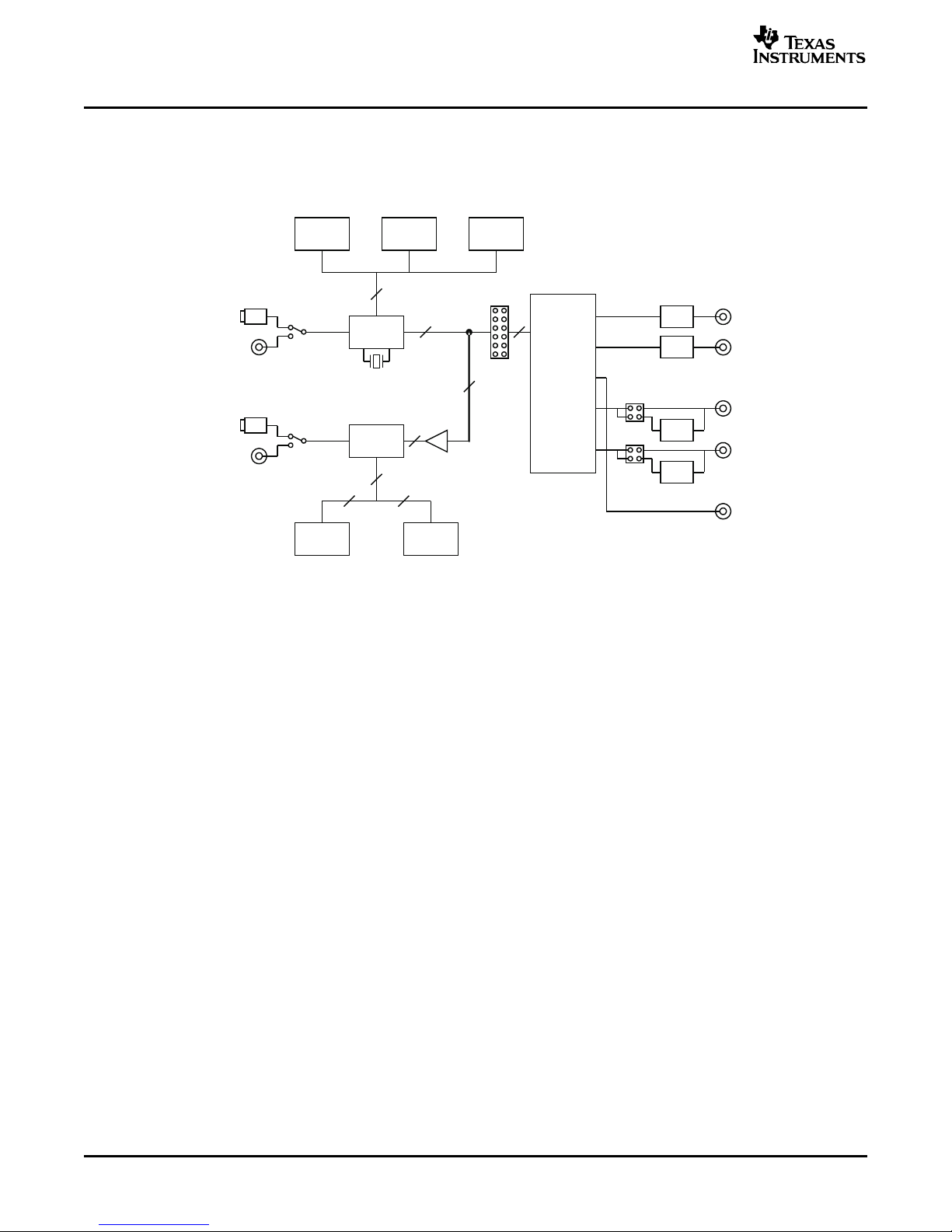
Block Diagram
1.1 Block Diagram
Figure 1-1. DEM-DAI3052A Block Diagram
Description 6 SLEU079 – September 2006
Submit Documentation Feedback
Page 7

www.ti.com
1.2 Basic Connection and Operation
1.2.1 Basic Connections and Configurations
• Install REGTEST_I2C and other programs attached to the EVM into the appropriate folder of the PC
that is used to control this EVM.
• Confirm EVM settings. SW053 must be all OFF (High). JP051 SCL, SDA, MDO, and DOUTS must be
OFF, OFF, OFF, and ON, respectively.
• Connect the 5-V and ± 15-V power supplies to V
3.3 V is used on CN056, jumper CN057 must be removed. The ± 15-V power supplies are required for
2-Vrms input and 2-Vrms output.
• Connect the SPDIF input to CN059 (coaxial) or U053 (optical) and output to CN058 (coaxial) or U052
(optical), and select coaxial or optical for SPDIF input and output using SW001 and SW051. Also,
select the SPDIF output source from the analog-to-digital converter (ADC) output or the
digital-to-analog converter (DAC) input using SW052.
• Select the system clock source from x’tal or SPDIF input recover clock using SW004, select the
system clock using SW003 SCF1/0 for DIR1703 and using SW005 CLK1/0 for DIT4096, and select the
system clock frequency for x’tal mode using JP001 setting.
• Set the interface format (24-bit I2S) using SW003 FMT1/0 for DIR1703 and using SW005 FMT1/0 for
DIT4096.
• Set the channel status for DIT4096 using SW006 if required. (It is not required for PCM3052A
evaluation.)
• Select the analog input/output configuration according to application interface, specifically, select the
DUT PCM3052A V
differential using JP110, the ADC input full scale from 2 Vrms or 1 Vrms using JP105/6, and the DAC
output LPF band width from 20 kHz or 40 kHz using JP101-104.
Basic Connection and Operation
, ± AV
CC
from 5 V or 4.5 V using JP109, the Mic input configuration of single ended or
CC
, and GND on CN051–CN055. If external
CC
SLEU079 – September 2006 Description 7
Submit Documentation Feedback
Page 8
www.ti.com
Basic Connection and Operation
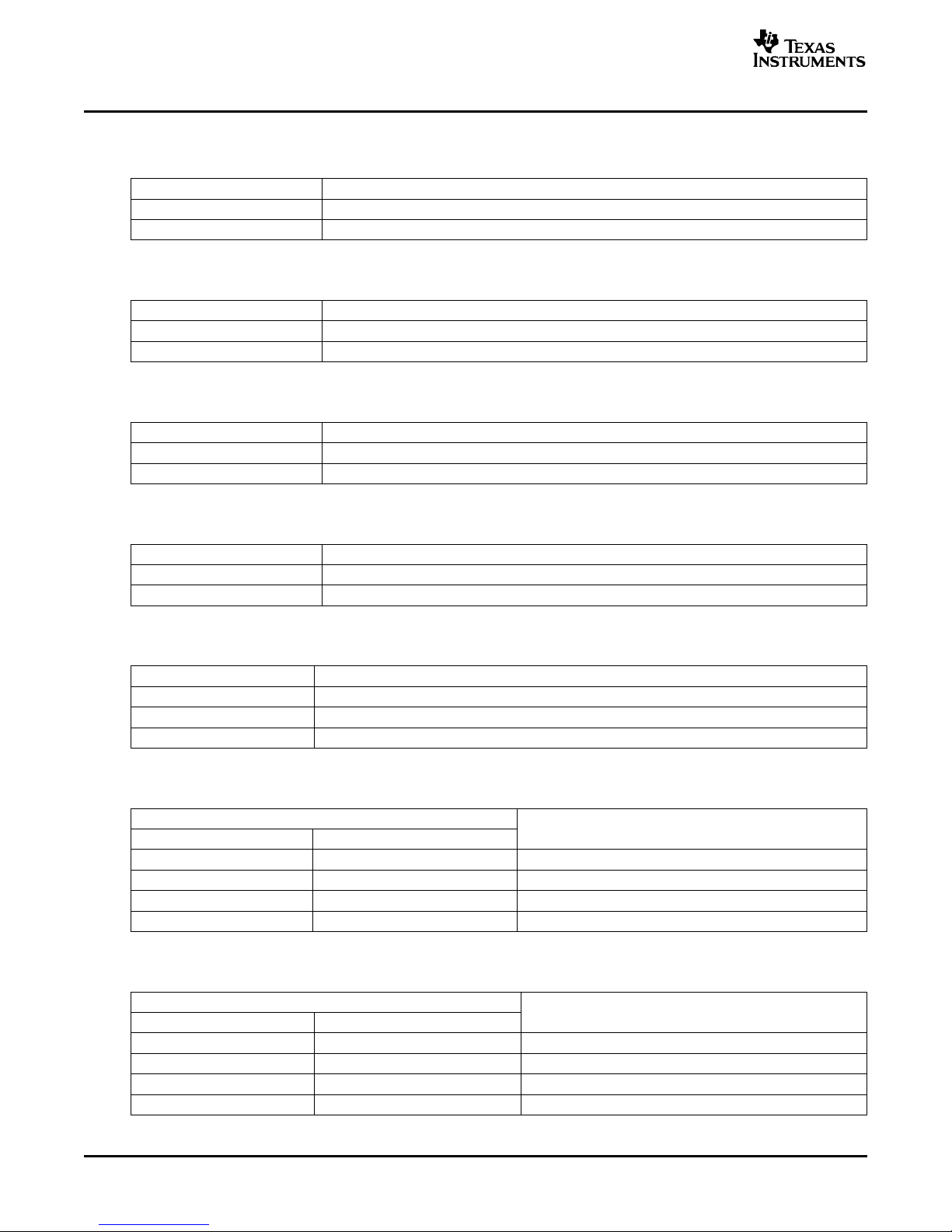
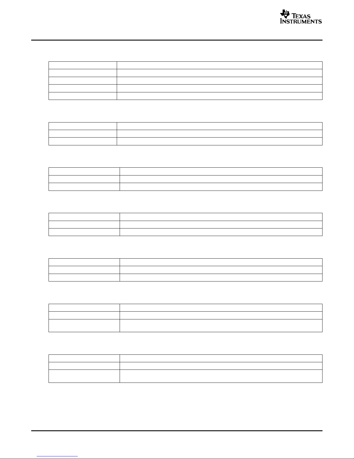
1.2.2 Configuration Controls
Table 1-1. CN057: 3.3-V Power Source Selection
CN057 DESCRIPTION
OFF 3.3 V must be supplied on CN056.
ON 3.3 V must be supplied by on board regulator, U051 (default).
Table 1-2. SW001: SPDIF Input Selection
SW001 DESCRIPTION
COAX Select coaxial connector as SPDIF input (default)
OPT Select optical connector as SPDIF input
Table 1-3. SW051: SPDIF Output Selection
SW051 DESCRIPTION
COAX Select coaxial connector as SPDIF output
OPT Select optical connector as SPDIF output (default)
Table 1-4. SW052: SPDIF Output Source Signal Selection
SW052 DESCRIPTION
REC Select DOUTS of PCM3052A, DAC input
DIT Select DIT4096 output, ADC output (default)
Table 1-5. SW004: DIR1703 Clock Source Selection
SW004 DESCRIPTION
X’tal SCKO (system clock out) is generated from crystal clock.
PLL SCKO is generated from SPDIF recovery clock.
AUTO Source clock of SCKO is automatically selected according to PLL lock state (default).
Table 1-6. SW003: DIR1703 System Clock Selection
SW003
SCF1 SCF0
OFF (L) OFF (L) 128 f
OFF (L) ON (H) 256 fS(Default)
ON (H) OFF (L) 384 f
ON (H) ON (H) 512 f
S
S
S
DESCRIPTION
Table 1-7. SW005: DIT4096 Master Clock Selection
SW005
CLK1 CLK0
OFF (H) OFF (H) 512 f
OFF (H) ON (L) 384 f
ON (L) OFF (H) 256 fS(default)
ON (L) ON (L) Unused
S
S
DESCRIPTION
Description 8 SLEU079 – September 2006
Submit Documentation Feedback
Page 9
www.ti.com
Basic Connection and Operation
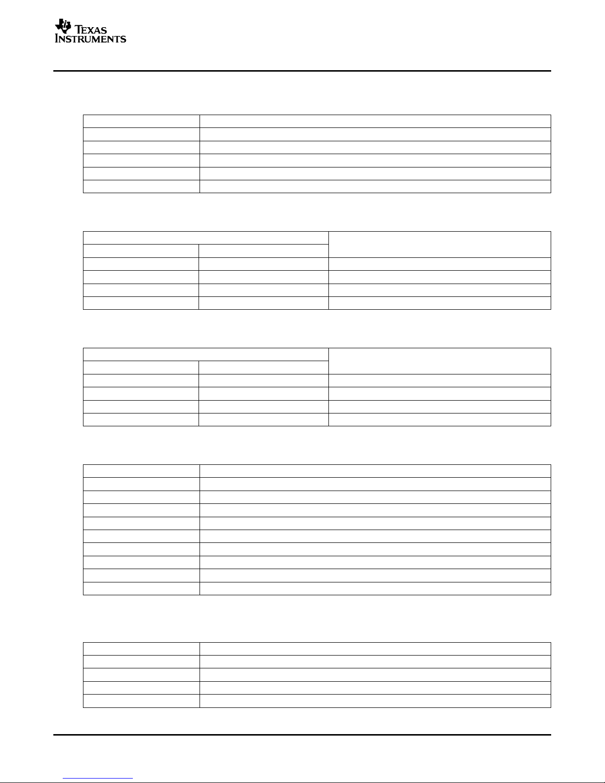
Table 1-8. JP001: DIR1703 Crystal Selection for Crystal Mode System Clock and Default Sampling
Frequency
JP001 DESCRIPTION
OPEN 6.144/12.288/18.432/24.576 MHz for 128 fS/256 fS/384 fS/512 fS, 48 kHz
CSBIT 12.288/24.576/36.864/49.152 MHz for 128 fS/256 fS/384 fS/512 fS, 96 kHz (default)
URBIT 11.2896/22.5792/33.8688/45.158 MHz for 128 fS/256 fS/384 fS/512 fS, 88.2 kHz
EMFLG 5.6448/11.2896/16.9344/22.5792 MHz for 128 fS/256 fS/384 fS/512 fS, 44.1 kHz
BFRAME 4.096/8.192/12.288/16.384 MHz for 128 fS/256 fS/384 fS/512 fS, 32 kHz
Table 1-9. SW003: DIR1703 Format Selection
SW003
FMT1 FMT0
OFF (L) OFF (L) 16 bits MSB first, right justified
OFF (L) ON (H) 24 bits MSB first, right justified
ON (H) OFF (L) 24 bits MSB first, left justified
ON (H) ON (H) 24 bits MSB first, I2S format (default)
DESCRIPTION
Table 1-10. SW005: DIT4096 Format Selection
SW005
FMT1 FMT0
OFF (H) OFF (H) 16-bit right justified
OFF (H) ON (L) 24-bit right justified
ON (L) OFF (H) 24-bit I2S (default)
ON (L) ON (L) 24-bit left justified
DESCRIPTION
Table 1-11. SW006: DIT4096 Channel Status Information Control
SW006 DESCRIPTION
CSS Channel status data mode input (default: on)
COPY-C Copy protect or channel status data input (default: on)
U User data input (default: on)
V Validity data input (default: on)
L Generation status input (default: on)
/AUDIO Audio data valid control input (default: on)
/EMPH Pre-emphasis status input (default: off)
BLSM Block start mode control input (default: off)
BLS Block start I/O (default: off)
(1)
Control of these switches is not required for PCM3052A function and performance evaluation.
Table 1-12. SW053: Mode Control
SW053 DESCRIPTION
RESET Function control that is defined on RESET (default: off)
MDI Function control that is defined on MDI (default: off)
MC Function control that is defined on MC (default: off)
ML Function control that is defined on ML (default: off)
(1)
SLEU079 – September 2006 Description 9
Submit Documentation Feedback
Page 10
www.ti.com
Basic Connection and Operation
Table 1-13. JP051: DOUTS or MDO Setting for Mode Control
JP051 DESCRIPTION
1/4 Change SCL configuration to MC configuration (default: off)
2/4 Change SCA configuration to MD configuration (default: off)
3/4 Enable MDO (default: off)
4/4 Enable DOUTS (default: on)
Table 1-14. JP109: DUT (PCM3052A) V
JP109 DESCRIPTION
LEFT DUT V
RIFHT DUT V
is supplied from external 5 V (default).
CC
is supplied from onboard 4.5-V regulator
CC
Table 1-15. JP110: MIC Input Configuration
JP110 DESCRIPTION
LEFT Single-ended microphone input
RIFHT Differential microphone input (default)
Table 1-16. JP101-104: Lineout LPF Selection
JP101,102,103,104 DESCRIPTION
OFF 40-kHz BW
ON 20-kHz BW (default)
Table 1-17. JP105, JP106: ADC Input Level Selection
JP105,106 DESCRIPTION
1 Vrms 1.06-Vrms full-scale voltage on ADC inputs (default)
2 Vrms 2.12-Vrms full-scale voltage on ADC inputs
CC
Supply Voltage Selection
Table 1-18. JP107: Bridge for PCM Audio Interface
JP107 DESCRIPTION
ON All straps must be mounted for interfacing onboard SPDIF receiver/transmitter.
OFF
Table 1-19. JP108: Bridge for Mode Control Interface
JP108 DESCRIPTION
ON All straps must be mounted for interfacing with PC via CN060.
OFF
Description 10 SLEU079 – September 2006
All straps must be removed and connecting external audio interface signals on JP107 (signal) –
JP111 (GND) for interfacing with external equipment.
All straps must be removed and connecting external control interface signals on right-side of
JP108 for interfacing with external equipment.
Submit Documentation Feedback
Page 11

www.ti.com
1.2.3 DEM-DAI3052A EVM Operation
Start
Run EVM control software by double clicking REGTEST_I
Initialization
Click pulldown menu, and select “High” for “ENABLE(L)”, “High-Pulse” for “SCL(C)”, “SDA(D)”, and
“Low-Pulse” for “Reset(R)” for standard control.
Send Command
Click box, which should be set to “1”, so that address and data is set to desired value. Click pulldown
menu, “Execute (E)”, and select “Send (S)”, so that command that is already set up is sent through the
printer port.
Basic Connection and Operation
2
C.
SLEU079 – September 2006 Description 11
Submit Documentation Feedback
Page 12

www.ti.com
PCM3052A, DAC, 48kHz,0dB
-140
+0
-130
-120
-110
-100
-90
-80
-70
-60
-50
-40
-30
-20
-10
d
B
r
A
2k 20k4k 6k 8k 10k 12k 14k 16k 18k
Typical Performance and Measurement Example
1.3 Typical Performance and Measurement Example
The following graphs show typical performance and FFT results for the ADC and DAC.
12 Description SLEU079 – September 2006
Submit Documentation Feedback
Page 13

www.ti.com
PCM3052A, DAC, 48kHz, –60dB
-140
+0
-130
-120
-110
-100
-90
-80
-70
-60
-50
-40
-30
-20
-10
d
B
r
A
2k 20k4k 6k 8k 10k 12k 14k 16k 18k
Hz
Typical Performance and Measurement Example
SLEU079 – September 2006 Description 13
Submit Documentation Feedback
Page 14

www.ti.com
PCM3052A, ADC, 48kHz,Line, –0.5dB
-140
+0
-130
-120
-110
-100
-90
-80
-70
-60
-50
-40
-30
-20
-10
d
B
F
S
2k 20k4k 6k 8k 10k 12k 14k 16k 18k
Hz
Typical Performance and Measurement Example
Description 14 SLEU079 – September 2006
Submit Documentation Feedback
Page 15

www.ti.com
PCM3052A, ADC, 48kHz,Line, –60dB
-140
+0
-130
-120
-110
-100
-90
-80
-70
-60
-50
-40
-30
-20
-10
d
B
F
S
2k 20k4k 6k 8k 10k 12k 14k 16k 18k
Hz
Typical Performance and Measurement Example
SLEU079 – September 2006 Description 15
Submit Documentation Feedback
Page 16

www.ti.com
PCM3052A, ADC, 48kHz,Mic,Noinputsignal
-140
+0
-130
-120
-110
-100
-90
-80
-70
-60
-50
-40
-30
-20
-10
d
B
F
S
2k 20k4k 6k 8k 10k 12k 14k 16k 18k
Hz
Typical Performance and Measurement Example
Description 16 SLEU079 – September 2006
Submit Documentation Feedback
Page 17

www.ti.com
PCM3052A, ADC, 48kHz,Micwith20dBgain,Noinputsignal
-140
+0
-130
-120
-110
-100
-90
-80
-70
-60
-50
-40
-30
-20
-10
d
B
F
S
2k 20k4k 6k 8k 10k 12k 14k 16k 18k
Hz
Typical Performance and Measurement Example
SLEU079 – September 2006 Description 17
Submit Documentation Feedback
Page 18

www.ti.com
Typical Performance and Measurement Example
Description 18 SLEU079 – September 2006
Submit Documentation Feedback
Page 19

SLEU079 – September 2006
Schematics and Printed Circuit Boards
This chapter presents the DEM-DAI3052A schematics, Bill of Materials (BOM), and
printed circuit boards.
Topic .................................................................................................. Page
2.1 DEM-DAI3052A Schematics ........................................................ 20
2.2 DEM-DAI3052A Bill of Materials (BOM) ........................................ 24
2.3 DEM-DAI3052A Printed Circuit Boards ......................................... 27
Chapter 2
SLEU079 – September 2006 Schematics and Printed Circuit Boards 19
Submit Documentation Feedback
Page 20

www.ti.com
V
CC
C056
10uF
/16V
C054
100uF
/16V
C053
100uF
/16V
C051
0.1uF
AVCC-
AVCC+
2
1
3
GND
INOUT
C055 0.1uF
U051
REG1117-3.3
CN057
FFC-2BMEP1
V
DD
CN051
banana jack
(Orange)
CN055
banana jack
(Black)
CN053
banana jack
(Blue)
CN054
banana jack
(Red)
CN052
banana jack
(Green)
CN056 B2P-VH
U053
TORX179P
C060
10uF
/16V
R053
75
C059
0.1uF
CN058
RCA pj
R051
90.9
C057
0.1uF
C058
10uF
/16V
U052
TOTX179P
TR001
DA-02
CN059 RCA pj
R052 374
C064
0.1uF
20
19
18
17
16
15
14
13
12
11
2/4[SDA]
3/4[MDO]
C062 0.1uF
1
2
3
4
5
6
7
8
9
10
Vcc
GND
U054 74LVC244
[ML]
[MC]
[MDI]
[RESET]
MDI
MDO
MC
RESET
ML
[MDO]
REC-out
OPT-in
COAX-in
DIT-out
4/4
[DOUTS]
1/4[SCL]
R055
10k
D051
1SS133
JP051
FFC-8BMEP1
D052
1SS133
R054
10k
CN060 57LE-40360-7700(D3)
SW053 DSS104 RA051
47k x 5
1
2
3
4
C061
0.1uF
SW051
FT1D-2M
OPTICAL
COAXIAL
OPT/COAX-out
select
SW052
FT1D-2M
REC-OUT
DIT-OUT
DIT/REC-out
SW054
FP1F-2M
D053
1SS133
470
R056
C063
10uF/16V
RESET
MDI
MC
ML
D054
1SS133
D055
1SS133
2 1
1
2 3 4 5
3
1 2 4 5
541
6 2
3
V
CC
C056
10uF
/16V
C054
100uF
/16V
C053
100uF
/16V
C051
0.1uF
C052
100uF
/16V
AVCC-
AVCC+
2
1
3
GND
INOUT
C055 0.1uF
U051
REG1117-3.3
CN057
FFC-2BMEP1
V
DD
CN051
banana jack
(Orange)
CN055
banana jack
(Black)
CN053
banana jack
(Blue)
CN054
banana jack
(Red)
CN052
banana jack
(Green)
CN056 B2P-VH
U053
TORX179P
C060
10uF
/16V
R053
75
C059
0.1uF
CN058
RCA pj
R051
90.9
C057
0.1uF
C058
10uF
/16V
U052
TOTX179P
TR001
DA-02
CN059 RCA pj
R052 374
C064
0.1uF
20
19
18
17
16
15
14
13
12
11
2/4[SDA]
3/4[MDO]
C062 0.1uF
1
2
3
4
5
6
7
8
9
10
Vcc
GND
U054 74LVC244
[ML]
[MC]
[MDI]
[RESET]
MDI
MDO
MC
RESET
ML
[MDO]
REC-out
OPT-in
COAX-in
DIT-out
4/4
[DOUTS]
1/4[SCL]
R055
10k
D051
1SS133
JP051
FFC-8BMEP1
D052
1SS133
R054
10k
CN060 57LE-40360-7700(D3)
SW053 DSS104 RA051
47k x 5
1
2
3
4
C061
0.1uF
SW051
FT1D-2M
OPTICAL
COAXIAL
OPT/COAX-out
select
SW052
FT1D-2M
REC-OUT
DIT-OUT
DIT/REC-out
SW054
FP1F-2M
D053
1SS133
470
R056
C063
10uF/16V
RESET
MDI
MC
ML
D054
1SS133
D055
1SS133
2 1
1
2 3 4 5
3
1 2 4 5
541
6 2
3
19 20 21 22 23 24 25 26 27 28 29 30 31 32 33 34 35 36
1 2 3 4 5 6 7 8 9 10 11 12 13 14 15 16 17 18
DEM-DAI3052A Schematics
2.1 DEM-DAI3052A Schematics
20 Schematics and Printed Circuit Boards SLEU079 – September 2006
Figure 2-1. DEM-DAI3052A Power and Interface Section
Submit Documentation Feedback
Page 21

www.ti.com
10
9
8
7
6
5
4
3
2
1
U001
74HCU04
U002 DIR1703
C001
0.1uF
C008
10uF
/16V
C009
0.1uF
C004 0.1uF
SW001
FT1D-2M
Vcc
GND
1
2
3
4
5
6
7
14
13
12
11
10
9
8
R001
47k
R002
2.2k
C007
18pF
C006
18pF
X001
24.576MHz
R005
1M
C010
10uF
/16V
C011
0.1uF
R006
1.2k
C013
8200pF
C012
0.068uF
R003
47k
R004
470
D001
1SS133
SW002
FP1F-2M
C005
10uF
/16V
CN001
FFC-10AMEP1
SW004
FT1E-2M
[BRATE0]
[ADFLG]
[BRATE1]
SW003
DSS104
4
3
2
1
C003
10uF
/16V
2
1
3
GND
INOUT
C002
0.1uF
U003 REG1117-3.3
[BRSEL]
[URBIT]
[EMFLG]
[CSBIT]
[BFRAME]
1
2
3
4
5
6
7
8
9
10
11
12
13
14
ADFLG
BRATE0
BRATE1
SCKO
V
DD
DGND
XTO
XTI
CKTRNS
LRCKO
BCKO
DOUT
SCF0
SCF1
28
27
26
25
24
23
22
21
20
19
18
17
16
15
CKSEL
UNLOCK
FMT1
FMT0
V
CC
AGND
FILT
RST
DIN
BRSEL
BFRAME
EMFLG
URBIT
CSBIT
DIR1703
1
2
3
4
5
6
7
8
9
10
11
12
13
14
CSS
COPY/C
L
CLK1
CLK0
MCLK
V
DD
DGND
FMT0
FMT1
SCLK
SYNC
SDATA
M/S
28
27
26
25
24
23
22
21
20
19
18
17
16
15
MODE
U
V
BLS
BLSM
EMPH
AUDIO
MONO
MDAT
V
DD
TX+
TX-
DGND
RST
DIT4096
[BCK]
[TX-DATA]
[SCLK]
[LRCK]
[RX-DATA]
[BCK]
[TX-DATA]
[LRCK]
[BCK]
[SCLK]
[LRCK]
[RX-DATA]
[SCLK]
1
2
3
4
5
6
7
8
C015
10uF/16V
C014
0.1uF
1
2
3
4
5
6
7
8
9
10
Vcc
GND
20
19
18
17
16
15
14
13
12
11
U005
74HCT244
FMT1
FMT0
CLK1
CLK0
C017
10uF/16V
C016
0.1uF
C018 0.1uF
DIT-out
OPT-in
COAX in
V
CC
MDI
RESET
SCLK
RX-DATA
MDO
GND
MC
ML
LRCLK
TX-DATA
BCLK
V
CC
CSS
COPY/C
U
V
L
AUDIO
EMPH
BLSM
BLS
CN002
FFC
-9AMEP1
U004 DIT4096
SW006
DSS110
SW005
DSS108
RA001
47k x 5
RA003
47k x 9
RA002
47k x 3
REC-out
C019
10uF
/16V
C020
10uF
/16V
X’tal
Auto
Clock mode select
PLL
CN003
XB-3-7-20
CN004
XB-3-7-20
GND
C021
0.1uF
FMT1
FMT0
SCF1
SCF0
COAX
OPT
JP001
FFC
-10BMEP1
BRATE0
ADFLG
BRATE1
CKTRNS
URBIT
EMFLG
CSBIT
GND
UNLOCK/PE
JP002
FFC
-3AMEP1
BFRAME
DEM-DAI3052A Schematics
SLEU079 – September 2006 Schematics and Printed Circuit Boards 21
Figure 2-2. DEM-DAI3052A Digital Section (Digital Audio Interface)
Submit Documentation Feedback
Page 22

www.ti.com
171819
21
C110
120pF
CN101
RCA pj
R109
2.4k
C113
10uF
/16V
C117 330pF
C115
1800pF
R111
3.3k
U102
OPA2134PA
1/2
R113 1.2k
2
3
1
4
C111
10uF
/16V
C112
10uF
/16V
R102
10k
JP102
1/2
U101
OPA2134PA
2/2
R104
1k
R106 15k
C108 120pF
C106
1200pF
6
5
7
8
AVCC+
AVCC-
R108
100
C104
1200pF
CN106
RCA pj
JP102
2/2
JP104
CN102
RCA pj
R110
2.4k
C114
10uF
/16V
C118 330pF
C116
1800pF
R112
3.3k
U103
OPA2134PA
1/2
R114 1.2k
2
3
1
4
C102
10uF
/16V
JP101/102: FFC-4BMEP1
JP103/104: FFC-2BMEP1
MDI
RESET
MC
ML
MDO
GND
SCKI
SDA
SCL
I
2
CEN
BCLK
SCLK
LRCLK
RX-DATA
TX-DATA
GND
DUT BLOCK
JP107
FFC-
12BMEP1
JP108
FFC-12BMEP1
R123
R122
R121
R120
R119
PDWN
LRCK
BCK
DIN
DOUT
DOUTS
DGND
V
DD
DG
V
DD
(3.3V)
9
10
11
12
13
14
15
16
100 x 5
100 x 3
V
IN
R
632
C109
120pF
R101
10k
CN105
RCA pj
U101
OPA2134PA
1/2
R103
1k
C107 120pF
C105
1200pF
2
3
1
4
R107
100
C103
1200pF
JP101
2/2
JP101
1/2
JP103
C101
10uF/16V
REFO
V
OUT
L
V
OUT
R
V
CC
AGND
7,23,31
8,22,30
25
24
32
29
28
R105 15k
MINP
CN103
MINM
LGY6502
R126
R125
R124
CN104
FFC-2BMEP1
JP109
FFC-4BMEP1
U104
REG103GA-A
VCC(5V)
C127
0.1uF
C128
10uF
/16V
R128
20k
R127
49.9k
C129
0.01uF
4 3
12
5
JP110
FFC-4BMEP1
C123
10uF/16V
C121
10uF
/16V
JP105
FFC
-4BMEP1
R115
4.7k
R117 4.7k
C119 100pF
U102
OPA2134PA
2/2
AVCC+
AVCC-
6
5
7
8
C126
10uF/16V
C124
10uF/16V
C122
10uF
/16V
JP106
FFC
-4BMEP1
R116
4.7k
R118 4.7k
C120 100pF
U103
OPA2134PA
2/2
AVCC+
AVCC-
6
5
7
8
C125
10uF/16V
2V
1V
2V
1V
D101
TLSU124
R129
3.3k
MIC
5V
4.5V
S/E
DIF
JP111
FFC
-6AMEP1
REFO
CN107-110
XB-3-6-8 X 4
V
IN
L
L/M
DEM-DAI3052A Schematics
22 Schematics and Printed Circuit Boards SLEU079 – September 2006
Figure 2-3. DEM-DAI3052A Analog Section
Submit Documentation Feedback
Page 23

www.ti.com
SCKI
SDA
SCL
ADR
I
2
CEN
AGND2
V
CC
2
V
OUT
R
V
OUT
L
LRCK
BCK
DIN
DOUT
DOUTS
DGND
V
DD
U151
PCM3052A
C
154
10uF/16V
C
160
1uF
C
159
1uF
C
157
10 uF/16V
R
152
1k
R
151
1k
C
153
REFO
V
CC
3
AGND3
MINP
MINM
MBIAS
V
COM
32
31
30
29
28
27
26
10
11
12
13
14
15
16
17 18 19 20 21 22 23 24 25
9 8 7 6 5 4 3 2 1
+
+
+
LRCK
V
IN
R
V
IN
L
I
2
CEN
MINP
MINM
SCL
REFO
V
CC
AGND
SDA
V
OUT
R
V
OUT
L
SCKI
V
DD
DGND
BCK
DIN
DOUT
DOUTS
+
+
C
152
10uF
/16V
C
164
0.1uF
C
162
0.1uF
C
168
0.1uF
C
167
0.1uF
C
151
10uF
/16V
C
156C155
++ +
+
C
161
0.1uF
10uF/16V x2
10 uF/16V
C
170
0.1uF
C
163
0.1uF
C
169
0.1uF
PDWN
C
158
10 uF/16V
C
165
10 uF/16V
+
PDWN
AGND1
V
CC
1
V
IN
R
V
REF
2
V
REF
1
L/M
V
IN
L
ATEST
L/M
DEM-DAI3052A Schematics
Figure 2-4. DEM-DAI3052A DUT Section
SLEU079 – September 2006 Schematics and Printed Circuit Boards 23
Submit Documentation Feedback
Page 24

www.ti.com
DEM-DAI3052A Bill of Materials (BOM)
2.2 DEM-DAI3052A Bill of Materials (BOM)
REFERENCE MANUFACTURER
DESIGNATORS PART NO.
D001, D051, D052,
D053, D054, D055
D101 LED TLSU124(F) Toshiba 1
U001 Hex Unbuffered Inverter SN74HCU04NS TI 1
U002 Digital Interface Receiver DIR1703DB TI 1
U003, U051 3.3-V Regulator REG1117-3.3 TI 2
U004 Digital Interface Transmitter DIT4096PW TI 1
U005 Octal Buffer Driver SN74HCT244NS TI 1
U052 TOSLINK Optical Transmitter TOTX179P Toshiba 1
U053 TOSLINK Optical Receiver TORX179P Toshiba 1
U054 Octal Buffer Driver SN74LVC244ANS TI 1
U101, U102, U103 Op Amp OPA2134PA TI 3
U104 Regulator IC REG103GA-A TI 1
U151 Stereo Audio Codec PCM3052A (DUT) TI 1
X001 Crystal Resonator HC-49/U-S-24.576 MHz 24.576 MHz Kinseki 1
C001, C061 Polyester Film Capacitor AMCF0050J104 0.1 uF Nissei Electronic 2
C012 Polyester Film Capacitor AMZF0050J683 0.068 uF Nissei Electronic 1
C013 Polyester Film Capacitor AMCF0050J822 8200 pF Nissei Electronic 1
C103, C104, C105,
C106
C107, C108, C109,
C110
C115, C116 Polypropylene Film Capacitor APSF0100J182 1800 pF Nissei Electronic 2
C117, C118 Polypropylene Film Capacitor APSF0100J331 330 pF Nissei Electronic 2
C119, C120 Polypropylene Film Capacitor APSF0100J101 100 pF Nissei Electronic 2
C002, C004, C018,
C051, C055, C057,
C059, C062, C127,
C021, C064
C006, C007 Ceramic Capacitor RPE2C1H180J2P1Z01B 18 pF Murata 2
C129 Ceramic Capacitor RPER11H103K2P1A01B 0.01 uF Murata 1
C009, C011, C014,
C016, C161, C162, 0.1 uF/25 V
C163, C164, C167, 1608 type
C168, C169, C170
C003, C005, C008,
C010, C015, C017,
C056, C058, C060,
C063, C111, C112,
C123, C124, C125, Electrolytic Capacitor R3A-16V100M 10 uF/16 V ELNA 26
C126, C128, C151,
C152, C153, C154,
C155, C156, C157,
C158, C165
C052, C053, C054 Electrolytic Capacitor ROA-16V101M 100 uF/16 V ELNA 3
C101, C102, C113,
C114, C121, C122
C159, C160 Electrolytic Capacitor UEP1H010MDT 1 uF, Bi-polar Nichicon 2
PART DESCRIPTION SPECIFICATION MANUFACTURER QTY
Diode 1SS133 ROHM 6
Polypropylene Film Capacitor APSF0100J122 1200 pF Nissei Electronic 4
Polypropylene Film Capacitor APSF0100J121 120 pF Nissei Electronic 4
Ceramic Capacitor RPEF11H104Z2K1A01B 0.1 uF Murata 11
Chip Ceramic Capacitor GRM188B11E104KA01 Murata 12
Electrolytic Capacitor ROA-16V100M 10 uF/16 V ELNA 6
R001, R003 Metal Film Resistor MFS1/4CC-47k Ω F 1/8 W, 47 k Ω KOA 2
R002 Metal Film Resistor MFS1/4CC-2.2k Ω F 1/8 W, 2.2 k Ω KOA 1
24 Schematics and Printed Circuit Boards SLEU079 – September 2006
Submit Documentation Feedback
Page 25

www.ti.com
DEM-DAI3052A Bill of Materials (BOM)
REFERENCE MANUFACTURER
DESIGNATORS PART NO.
R004, R056 Metal Film Resistor MFS1/4CC-470 Ω F 1/8 W, 470 Ω KOA 2
R005 Metal Film Resistor MFS1/4CC-1M Ω F 1/8 W, 1 M Ω KOA 1
R006, R113, R114 Metal Film Resistor MFS1/4CC-1.2k Ω F 1/8 W, 1.2 k Ω KOA 3
R051 Metal Film Resistor MFS1/4CC-90.9 Ω F 1/8 W, 90.9 Ω KOA 1
R052 Metal Film Resistor MFS1/4CC-374 Ω F 1/8 W, 374 Ω KOA 1
R053 Metal Film Resistor MFS1/4CC-75 Ω F 1/8 W, 75 Ω KOA 1
R054, R055, R101,
R102
R103, R104, R151,
R152
R105, R106 Metal Film Resistor MFS1/4CC-15k Ω F 1/8 W, 15 k Ω KOA 2
R107, R108, R119,
R120, R121, R122,
R123, R124, R125,
R126
R109, R110 Metal Film Resistor MFS1/4CC-2.4k Ω F 1/8 W, 2.4 k Ω KOA 2
R111, R112, R129 Metal Film Resistor MFS1/4CC-3.3k Ω F 1/8 W, 3.3 k Ω KOA 3
R115, R116, R117,
R118
R127 Metal Film Resistor MFS1/4CC-49.9k Ω F 1/8 W, 49.9 k Ω KOA 1
R128 Metal Film Resistor MFS1/4CC-20k Ω F 1/8 W, 20 k Ω KOA 1
RA001, RA051 Resistor Array M6-1-473J 47 k Ω × 5 Beckman 2
RA002 Resistor Array M4-1-473J 47 k Ω × 3 Beckman 1
RA003 Resistor Array M10-1-473J 47 k Ω × 9 Beckman 1
PART DESCRIPTION SPECIFICATION MANUFACTURER QTY
Metal Film Resistor MFS1/4CC-10k Ω F 1/8 W, 10 k Ω KOA 4
Metal Film Resistor MFS1/4CC-1k Ω F 1/8 W, 1 k Ω KOA 4
Metal Film Resistor MFS1/4CC-100 Ω F 1/8 W, 100 Ω KOA 10
Metal Film Resistor MFS1/4CC-4.7k Ω F 1/8 W, 4.7 k Ω KOA 4
TR001 Pulse Transformer DA-02 JPC 1
CN001 10-Pin Pin Header FFC-10AMEP1 Honda Tsushin 1
CN002 9-Pin Pin Header FFC-9AMEP1 Honda Tsushin 1
CN051 Banana Jack (Orange) T-45 (Orange) Sato Parts 1
CN052 Banana Jack (Green) T-45 (Green) Sato Parts 1
CN053 Banana Jack (Blue) T-45 (Blue) Sato Parts 1
CN054 Banana Jack (Red) T-45 (Red) Sato Parts 1
CN055 Banana Jack (Black) T-45 (Black) Sato Parts 1
CN056 2-Pin VH Connector B2P-VH(LF)(SN) JST 1
CN057 2-Pin Pin Header FFC-2BMEP1 Honda Tsushin 1
CN058, CN059 RCA Connector (Yellow) LPR6520-0804 (Yellow) SMK 2
CN060 57LE40360-7700(D3)-FA DDK 1
CN101, CN105 RCA Connector (White) LPR6520-0803 (White) SMK 2
CN102, CN106 RCA Connector (Red) LPR6520-0802 (Red) SMK 2
CN103 3.5 mm Stereo Min Plug YKB21-5274B JALCO 1
CN104 2-Pin Pin Header FFC-2AMEP1 Honda Tsushin 1
JP001 10-Pin Pin Header FFC-10BMEP1 Honda Tsushin 1
JP002 3-Pin Pin Header FFC-3AMEP1 Honda Tsushin 1
JP051 8-Pin Pin Header FFC-8BMEP1 Honda Tsushin 1
JP101, JP102,
JP105, JP106, 4-Pin Pin Header FFC-4BMEP1 Honda Tsushin 6
JP109, JP110
JP103, JP104 2-Pin Pin Header FFC-2BMEP1 Honda Tsushin 2
JP107 18-Pin Pin Header FFC-18NSM1 Honda Tsushin 1
Ribbon Connector
(Centronics)
SLEU079 – September 2006 Schematics and Printed Circuit Boards 25
Submit Documentation Feedback
Page 26

www.ti.com
DEM-DAI3052A Bill of Materials (BOM)
REFERENCE MANUFACTURER
DESIGNATORS PART NO.
JP108 12-Pin Pin Header FFC-12BMEP1 Honda Tsushin 1
SW001, SW051,
SW052
SW002, SW054 Push Switch FP1F-2M-Z Fujisoku 2
SW003, SW053 DIP Switch DSS104 4 elements Fujisoku 2
SW004 FT1E-2M-Z Fujisoku 1
SW005 DIP Switch DSS108 8 elements Fujisoku 1
SW006 DIP Switch DSS110 10 elements Fujisoku 1
PART DESCRIPTION SPECIFICATION MANUFACTURER QTY
Short Plug DIC-130 Honda Tsushin 28
Toggle Switch (DPDT) FT1D-2M-Z Fujisoku 3
Toggle Switch (DPDT With
Neutral)
Schematics and Printed Circuit Boards26 SLEU079 – September 2006
Submit Documentation Feedback
Page 27

www.ti.com
2.3 DEM-DAI3052A Printed Circuit Boards
DEM-DAI3052A Printed Circuit Boards
SLEU079 – September 2006 Schematics and Printed Circuit Boards 27
Submit Documentation Feedback
Figure 2-5. DEM-DAI3052A Top Silkscreen
Page 28

www.ti.com
DEM-DAI3052A Printed Circuit Boards
28 Schematics and Printed Circuit Boards SLEU079 – September 2006
Figure 2-6. DEM-DAI3052A Top Copper
Submit Documentation Feedback
Page 29

www.ti.com
DEM-DAI3052A Printed Circuit Boards
Figure 2-7. DEM-DAI3052A Bottom Copper
SLEU079 – September 2006 Schematics and Printed Circuit Boards 29
Submit Documentation Feedback
Page 30

www.ti.com
DEM-DAI3052A Printed Circuit Boards
Figure 2-8. DEM-DAI3052A Form, Dimension, and Drill
Schematics and Printed Circuit Boards30 SLEU079 – September 2006
Submit Documentation Feedback
Page 31

www.ti.com
EVM TERMS AND CONDITIONS
Texas Instruments (TI) provides the enclosed Evaluation Module and related material (EVM) to you, the user, (you or user) SUBJECT TO the terms and conditions set forth below . By accepting and using the EVM, you are indicating that you have read, un -
derstand and agree to be bound by these terms and conditions. IF YOU DO NOT AGREE TO BE BOUND BY THESE TERMS
AND CONDITIONS, YOU MUST RETURN THE EVM AND NOT USE IT.
This EVM is provided to you by TI and is intended for your INTERNAL ENGINEERING DEVELOPMENT OR EVALUATION PUR-
POSES ONLY. It is provided “AS IS” and “WITH ALL FAULTS.” It is not considered by TI to be fit for commercial use. As such, the
EVM may be incomplete in terms of required design−, marketing−, and/or manufacturing−related protective considerations, including product safety measures typically found in the end product. As a prototype, the EVM does not fall within the scope of the European Union directive on electromagnetic compatibility and therefore may not meet the technical requirements of the directive.
Should this EVM not meet the specifications indicated in the EVM User’s Guide, it may be returned within 30 days from the date of
delivery for a full refund of any amount paid by user for the EVM, which user agrees shall be user’s sole and exclusive remedy.
THE FOREGOING WARRANTY IS THE EXCLUSIVE WARRANTY MADE BY TI TO USER, AND IS IN LIEU OF ALL OTHER
WARRANTIES, EXPRESSED, IMPLIED, OR STATUTORY, INCLUDING ANY WARRANTY OF MERCHANTABILITY, FITNESS
FOR ANY PARTICULAR PURPOSE OR NON−INFRINGEMENT.
TI shall have no obligation to defend any claim arising from the EVM, including but not limited to claims that the EVM infringes third
party intellectual property. Further, TI shall have no liability to user for any costs, losses or damages resulting from any such claims.
User shall indemnify and hold TI harmless against any damages, liabilities or costs resulting from any claim, suit or proceeding
arising from user’s handling or use of the EVM, including but not limited to, (I) claims that the EVM infringes a third party’s intellectual property, and (ii) claims arising from the user’s use or handling of the EVM. TI shall have no responsibility to defend any such
claim, suit or proceeding.
User assumes all responsibility and liability for proper and safe handling and use of the EVM and the evaluation of the EVM. TI
shall have no liability for any costs, losses or damages resulting from the use or handling of the EVM. User acknowledges that the
EVM may not be regulatory compliant or agency certified (FCC, UL, CE, etc.). Due to the open construction of the EVM it is the
user’s responsibility to take any and all appropriate precautions with regard to electrostatic discharge.
EXCEPT TO THE EXTENT OF THE USER’S INDEMNITY OBLIGATIONS SET FORTH ABOVE, NEITHER P ARTY SHALL
BE LIABLE TO THE OTHER FOR ANY INDIRECT, SPECIAL, INCIDENTAL, OR CONSEQUENTIAL DAMAGES WHETHER
TI IS NOTIFIED OF THE POSSIBILITY OR NOT.
TI currently deals with a variety of customers for products, and therefore our arrangement with the user is not exclusive.
TI assumes no liability for applications assistance, customer product design, software performance, or infringement of
patents or services described herein.
User agrees to read the EVM User’s Guide and, specifically, the EVM warnings and Restrictions notice in the EVM User’s Guide
prior to handling the EVM and the product. This notice contains important safety information about temperatures and voltages.
It is user’s responsibility to ensure that persons handling the EVM and the product have electronics training and observe good
laboratory practice standards.
By providing user with this EVM, product and services, TI is NOT granting user any license in any patent or other intellectual
property right.
Mailing Address: Texas Instruments, Post Office Box 655303, Dallas, Texas 75265
Copyright 2006, Texas Instruments Incorporated
DEM-DAI3052A Printed Circuit Boards
SLEU079 – September 2006 Schematics and Printed Circuit Boards 31
Submit Documentation Feedback
Page 32

www.ti.com
EVM WARNINGS AND RESTRICTIONS
It is important to operate this EVM within the input voltage range and the output voltage range that is less than 120% of the
corresponding nominal voltage ranges described in the EVM user’s guide.
Exceeding the specified input range may cause unexpected operation and/or irreversible damage to the EVM. If there are
questions concerning the input range, please contact a TI field representative prior to connecting the input power.
Applying loads outside of the specified output range may result in unintended operation and/or possible permanent damage to the
EVM. Please consult the EVM User’s Guide prior to connecting any load to the EVM output. If there is uncertainty as to the load
specification, please contact a TI field representative.
During normal operation, some circuit components may have case temperatures greater than 50°C. The EVM is designed to
operate properly with certain components above 50°C as long as the input and output ranges are maintained. These components
include but are not limited to linear regulators, switching transistors, pass transistors, and current sense resistors. These types of
devices can be identified using the EVM schematic located in the EVM User’s Guide. When placing measurement probes near
these devices during operation, please be aware that these devices may be very warm to the touch.
Mailing Address: Texas Instruments, Post Office Box 655303, Dallas, Texas 75265
Copyright 2006, Texas Instruments Incorporated
DEM-DAI3052A Printed Circuit Boards
Schematics and Printed Circuit Boards32 SLEU079 – September 2006
Submit Documentation Feedback
Page 33

www.ti.com
IMPORTANT NOTICE
Texas Instruments Incorporated and its subsidiaries (TI) reserve the right to make corrections, modifications,
enhancements, improvements, and other changes to its products and services at any time and to discontinue
any product or service without notice. Customers should obtain the latest relevant information before placing
orders and should verify that such information is current and complete. All products are sold subject to TI’s
terms and conditions of sale supplied at the time of order acknowledgment.
TI warrants performance of its hardware products to the specifications applicable at the time of sale in accordance with TI’s standard warranty. T esting and other quality control techniques are used to the extent TI deems
necessary to support this warranty . Except where mandated by government requirements, testing of all parameters of each product is not necessarily performed.
TI assumes no liability for applications assistance or customer product design. Customers are responsible for
their products and applications using TI components. To minimize the risks associated with customer products
and applications, customers should provide adequate design and operating safeguards.
TI does not warrant or represent that any license, either express or implied, is granted under any TI patent right,
copyright, mask work right, or other TI intellectual property right relating to any combination, machine, or process in which TI products or services are used. Information published by TI regarding third−party products or
services does not constitute a license from TI to use such products or services or a warranty or endorsement
thereof. Use of such information may require a license from a third party under the patents or other intellectual
property of the third party, or a license from TI under the patents or other intellectual property of TI.
Reproduction of information in TI data books or data sheets is permissible only if reproduction is without alteration and is accompanied by all associated warranties, conditions, limitations, and notices. Reproduction of this
information with alteration is an unfair and deceptive business practice. TI is not responsible or liable for such
altered documentation.
Resale of TI products or services with statements different from or beyond the parameters stated by TI for that
product or service voids all express and any implied warranties for the associated TI product or service and is an
unfair and deceptive business practice. TI is not responsible or liable for any such statements.
Following are URLs where you can obtain information on other Texas Instruments products and application
solutions:
Products
Amplifiers
Data Converters
DSP
Interface
Logic
Power Mgmt
Microcontrollers
amplifier.ti.com
dataconverter.ti.com
dsp.ti.com
interface.ti.com
logic.ti.com
power.ti.com
microcontroller.ti.com
Applications
Audio
Automotive
Broadband
Digital Control
Military
Optical Networking
Security
Telephony
Video & Imaging
Wireless
www.ti.com/audio
www.ti.com/automotive
www.ti.com/broadband
www.ti.com/digitalcontrol
www.ti.com/military
www.ti.com/opticalnetwork
www.ti.com/security
www.ti.com/telephony
www.ti.com/video
www.ti.com/wireless
Mailing Address: Texas Instruments, Post Office Box 655303, Dallas, Texas 75265
Copyright 2006, Texas Instruments Incorporated
DEM-DAI3052A Printed Circuit Boards
SLEU079 – September 2006 Schematics and Printed Circuit Boards 33
Submit Documentation Feedback
 Loading...