

Page 1

Sub-1GHz 6LoWPAN Development kit
User’s Guide
Literature Number: SWRU298
September 2011
Page 2

CC-6LOWPAN-DK-868
Page 2 of 61
Abbreviations
Abbreviations used in this data sheet are described below.
6LoWPAN
IPv6 over Low Power Wireless Personal Area
Networks
IPv6
Internet Protocol version 6
ICMP
Internet Control Message Protocol
UDP
User Datagram Protocol
RS
Router Solicitation
RA
Router Advertisement
NS
Neighbor Solicitation
NA
Neighbor Advertisement
SLLAO
Source Link Layer Addressing Object
PIO
Prefix Information Object
ABRO
ARO DODAG
Destination Oriented Directed Acyclic Graph
DIS
DODAG Information Solicitation
DIO
DODAG Information Object
DAO
Destination Advertisement Object
DAO-ack
DAO acknowledge
ER
Edge Router
Page 3

CC-6LOWPAN-DK-868
Page 3 of 61
Table of Contents
TABLE OF CONTENTS ......................................................................................................................... 3
LIST OF FIGURES ................................................................................................................................. 4
LIST OF TABLES ................................................................................................................................... 5
1 6LOWPAN KIT OVERVIEW ........................................................................................................ 6
1.1 FEATURES ...................................................................................................................................... 7
1.2 WHAT‟S INCLUDED IN THE KIT? ........................................................................................................ 8
2 GETTING STARTED ................................................................................................................... 9
2.1 SETTING UP IPV6 ON YOUR PC ....................................................................................................... 9
2.2 IPV6 AND 6LOWPAN BASICS ....................................................................................................... 10
2.2.1 IPv6 Introduction ......................................................................................................................................................... 11
2.2.2 6LoWPAN Introduction ................................................................................................................................................ 11
2.3 EDGE ROUTER BOOTSTRAP PROSESS ........................................................................................... 11
2.4 NODEVIEW 2.0 ............................................................................................................................. 11
2.5 NETWORK ANALYZER APPLICATION ............................................................................................... 13
3 SOFTWARE ............................................................................................................................... 14
3.1 SENSINODE NAPSOCKET AND NANOSOCKET INTERFACE ............................................................... 14
3.2 SENSINODE NANOSTACK 2.0 LITE ................................................................................................. 15
3.2.1 Bootstrap process........................................................................................................................................................ 16
3.2.2 Synchronization ........................................................................................................................................................... 16
3.2.3 Neighbour Discovery and Router Solicitation ............................................................................................................... 17
3.2.4 RPL: IPv6 Routing Protocol for Low power and Lossy Networks ................................................................................. 17
3.2.5 Periodic processes ................................ ...................................................................................................................... 19
3.2.6 Error situations ............................................................................................................................................................ 19
3.3 CC-6LOWPAN-DK-868 SOFTWARE PROJECTS ........................................................................... 20
3.3.1 IDE installation ............................................................................................................................................................ 20
3.3.2 NanoHost Example (Network Analyzer) ....................................................................................................................... 21
3.3.3 NAPSocket Library ...................................................................................................................................................... 22
3.3.4 CC430F5137 Library Model (Network Analyzer) .......................................................................................................... 22
3.3.5 Programming the boards ................................................................ ............................................................................. 24
3.4 SENSINODE NAPSOCKET API ....................................................................................................... 25
3.4.1 Sensinode NAP Protocol API....................................................................................................................................... 26
3.5 SENSINODE NANOSOCKET API ..................................................................................................... 26
3.6 SENSINODE RF DYNAMIC CONFIGURATION API ............................................................................. 27
3.6.1 NanoSocket ................................................................................................................................................................. 27
3.6.2 NAPSocket .................................................................................................................................................................. 28
3.6.3 Node View 2.0 ............................................................................................................................................................. 28
3.7 SENSINODE NANOBOOT API ......................................................................................................... 29
3.7.1 Sensinode NanoBoot host tool .................................................................................................................................... 29
3.8 SENSINODE NODEVIEW 2.0 CUSTOM TABS .................................................................................... 29
3.8.1 Developing applications to run in custom tabs in NodeView 2.0 ................................................................................... 30
3.8.2 Exporting custom tabs to run as stand alone ............................................................................................................... 31
3.9 EDGE ROUTER (OMAP-L138) SOFTWARE ..................................................................................... 32
3.9.1 Sensinode NanoRouter 2.0 ......................................................................................................................................... 32
3.9.2 Startup scripts ............................................................................................................................................................. 32
3.9.3 Linux folder structure ................................................................................................................................................... 33
3.9.4 Sensinode NanoBoot host tool .................................................................................................................................... 33
3.9.5 Debug/console interface .............................................................................................................................................. 33
4 HARDWARE .............................................................................................................................. 33
4.1 EM430F5137RF900 ................................................................................................................... 33
4.1.1 Programming/Reprogramming the EM430F5137RF900 .............................................................................................. 34
4.1.2 Debug Interface using UART ....................................................................................................................................... 34
4.1.3 Schematics, BOM and Layout ..................................................................................................................................... 34
4.2 CC1180DB ................................................................................................................................. 40
4.2.1 Programming/Reprogramming the CC1180DB ............................................................................................................ 41
4.2.2 Schematics, BOM and Layout ..................................................................................................................................... 41
4.3 EDGE ROUTER, OMAP-L138 EXPERIMENTERS BOARD .................................................................. 50
4.3.1 Adapter Board ............................................................................................................................................................. 51
4.3.2 CC1180EM .................................................................................................................................................................. 55
5 FAQ ............................................................................................................................................ 60
5.1 SEND UDP PACKETS FROM PC ..................................................................................................... 60
Page 4

CC-6LOWPAN-DK-868
Page 4 of 61
5.2 TOO MUCH CODE ......................................................................................................................... 60
5.3 LINUX KERNEL AND FILE SYSTEM ................................................................................................... 60
6 REFERENCES ........................................................................................................................... 61
7 DEVELOPMENT KIT ORDERING INFORMATION .................................................................. 61
8 GENERAL INFORMATION ....................................................................................................... 61
8.1 DOCUMENT HISTORY .................................................................................................................... 61
List of Figures
Figure 1. Sensinode NodeView Network Analyzer tool .......................................................... 6
Figure 2. CC-6LOPWAN-DK-868 kit ..................................................................................... 8
Figure 3. Kit System Overview .............................................................................................. 9
Figure 4. IPv6 enabled for Windows XP .............................................................................. 10
Figure 5. Adding an Edge Router. ....................................................................................... 12
Figure 6. NanoRouter Router View details. ......................................................................... 12
Figure 7. NodeView Network Analyzer tab. ......................................................................... 13
Figure 8. Stack overview CC1180 based system, using NAPSocket API ............................ 15
Figure 9. Stack Overview CC430 based system, using NanoSocket API ............................ 15
Figure 10. NanoHost Example project ................................................................................. 22
Figure 11. NAPSocket library project .................................................................................. 22
Figure 12. NanoSocket Example project ............................................................................. 23
Figure 13. Enabling the NanoSocket Debug Interface ......................................................... 23
Figure 14. Sensinode NAPSocket library ................................................................ ............ 26
Figure 15. Sensinode NanoSocket API ............................................................................... 27
Figure 16. Setting RF Configuration on Edge Router .......................................................... 28
Figure 17. Creating Eclipse project for NodeView 2.0 custom tab ....................................... 30
Figure 18. Folder structure for custom tabs ......................................................................... 30
Figure 19. tabConfig.txt file ................................................................................................. 31
Figure 20. EM430F5137RF900, Logical Description ........................................................... 34
Figure 21. EM430F5137RF900, PCB Components Top Layer ............................................ 36
Figure 22. EM430F5137RF900, PCB Components Bottom Layer ....................................... 36
Figure 23. EM430F5137RF900, Layout Top Layer ............................................................. 37
Figure 24. EM430F5137RF900, Layout Layer 2.................................................................. 37
Figure 25. EM430F5137RF900, Layout Layer 3.................................................................. 38
Figure 26. EM430F5137RF900, Layout Bottom Layer ........................................................ 38
Figure 27. CC1180DB, Logical Description ......................................................................... 40
Figure 28. CC1180DB, PCB Components Top Layer .......................................................... 45
Figure 29. CC1180DB, PCB Components Bottom Layer ..................................................... 46
Figure 30. CC1180DB, Layout Top Layer ........................................................................... 47
Figure 31. CC1180DB, Layout Bottom Layer ...................................................................... 48
Figure 32. OMAP-L138 Experimenter's Board Overview ..................................................... 50
Figure 33. Adapter Board, PCB Components Top Layer ..................................................... 53
Figure 34. Adapter Board, PCB Components Bottom Layer ................................................ 53
Figure 35. Adapter Board, Layout Top layer ........................................................................ 54
Figure 36. Adapter Board, Layout Bottom Layer ................................................................. 54
Figure 37. CC1180EM, PCB Components Top Layer ......................................................... 57
Figure 38. CC1180EM, PCB Components Bottom Layer .................................................... 57
Figure 39. CC1180EM, Layout Top Layer ........................................................................... 58
Figure 40. CC1180EM, Layout Bottom Layer ...................................................................... 58
Page 5

CC-6LOWPAN-DK-868
Page 5 of 61
List of Tables
Table 1. CC1180 controlled LED (D1 and D2) behavior. ..................................................... 14
Table 2. MSP4305438A controlled LED (D3 and D4) behavior. .......................................... 14
Table 3. Sensinode 6LoWPAN Stack Layer Definitions. ...................................................... 16
Table 4. Beacon payload. ................................................................................................... 16
Table 5. Fixed Neighbor Discovery packet formats. ............................................................ 17
Table 6. RPL control messages .......................................................................................... 18
Table 7. Fixed formats of RPL control messages. ............................................................... 18
Table 8. RPL Objective Code Point. .................................................................................... 18
Table 9. RPL Metric container format. ................................................................................. 19
Table 10. DODAG configuration parameters. ...................................................................... 19
Table 11. EM430F5137RF900, Bill of Material .................................................................... 40
Table 12. CC1180DB, Bill of Material .................................................................................. 50
Table 13. Adapter Board LED functionality .......................................................................... 51
Table 14. Adapter Board, Bill of Material ............................................................................. 55
Table 15. CC1180EM, Bill of Material ................................................................................. 59
Table 16. Development Kit Ordering Information ................................................................. 61
Table 17. Document History ................................................................................................ 61
Page 6
CC-6LOWPAN-DK-868
Page 6 of 61
1 6LoWPAN Kit Overview
This document describes the TI 6LoWPAN evaluation kit for use in the 868/915MHz bands. The kit is
based on hardware from TI and 6LoWPAN software (NanoStack) from TI third party Sensinode Ltd.
The CC-6LOWPAN-DK-868 kit provides easy way for users to start developing their own wireless
sensor network applications based on 6LoWPAN technology. There are two different APIs for
communicating with the NanoStack, based on if you use CC1180 Network Processor or the CC430
SoC. The API used for CC1180 is called NAPSocket, while the API for CC430 is called NanoSocket.
The kit contains a 6LoWPAN Edge Router (access point/gateway to IPv6) based on TI‟s OMAP-L138
processor. The Edge Router (ER) uses a CC1180EM as radio interface. The Edge Router is running
Sensinode Ltd NanoRouter 2.0 software and can connect wireless sensor nodes running Sensinode
Ltd NanoStack 2.0 lite. The evaluation version of NanoRouter 2.0 included in the kit is limited to 10
nodes per Edge Router.
Included in the kit are two EM430F5137RF900 Rev 3.2 boards and two CC1180DB boards. The
EM430F5137RF900 and CC1180DB boards are used as wireless sensor devices in the kit. CC430
comes with library support for Sensinode NanoStack 2.0 lite (NanoSocket [8]). This library model
allows easy implementation of user applications, built directly on top of the NanoSocket library.
The CC1180DB contains a Wireless Network Processor (WNP), CC1180, which handles all
6LoWPAN network communication. Connected to the WNP is a host processor (MPS430F5438A)
running the user application. The hardware interface between the network processor and the host
processor is UART. The software interface between the network processor and the host MCU is
Sensinode NAPSocket API [12]. The NAPSocket API acts as a wrapper library to parse Sensinode
NAP protocol messages [9].
The kit provides Edge Router (NanoRouter) control and testing software (Sensinode NodeView 2.0
[10]). NodeView 2.0 can be used to control NanoRouter software running on the Edge Router in real
time and provides e.g. address information of the connected nodes. The control protocol is based on
Sensinode proprietary UDP communication. The NodeView 2.0 tool also provides a simple way to
create user‟s own java applications that are included in the NodeView 2.0 GUI in the form own
separate tabs.
All nodes can act as routers inside the 6LoWPAN network. The radio transceivers on the nodes are
thus always on, which makes the system less suitable for battery-powered devices.
This documentation gives detailed information of the kit contents and behavior, its configuration and
how the different 6LoWPAN standards are implemented.
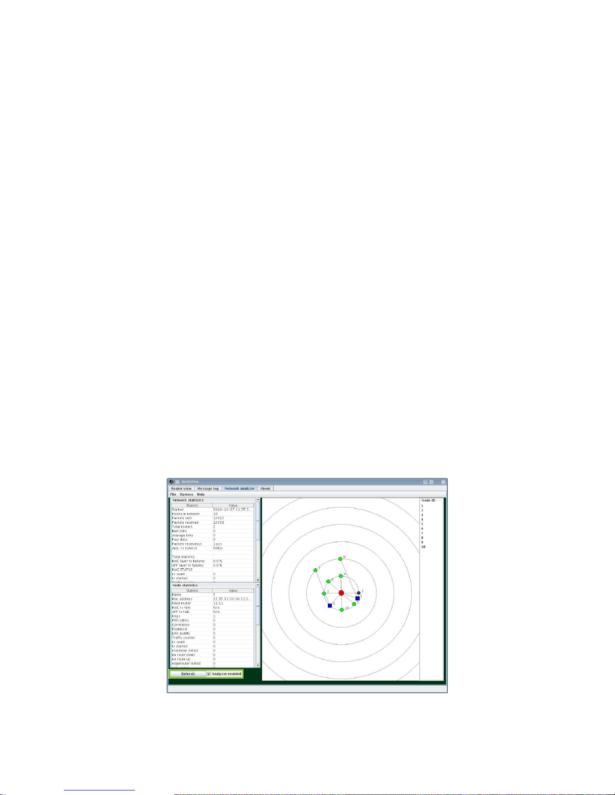
Figure 1. Sensinode NodeView Network Analyzer tool
Page 7

CC-6LOWPAN-DK-868
Page 7 of 61
1.1 Features
IP-based networking, enabling the “Internet of Things”
CC1180 Over-Network Download (OTA), future proofs:
o Device applications and network upgrades
Low memory footprint;
o CC1180 6LoWPAN stack is less than 32kB
o CC430 6LoWPAN stack is about 17kB
Sensinode 6LoWPAN software can run on all frequencies that CC1180 and CC430 support,
providing a sub-GHz mesh solution. Note: The kit hardware is for use in the 868/915 MHz
bands.
Low development complexity, customers used to IP programming will be up and running in no
time with the simple socket API approach.
Configurable RF interface:
o Output power: -30dBm to +10dBm
o Date rates: 50, 100, 150 and 200kbit/s
o RX Attenuation, for close-in systems
o AES-CCM* secured IEEE802.15.4e payloads, using network-wide key.
Coordinated mesh networking (modified RPL)
IEEE802.15.4g/e PHY and MAC
Compressed IPv6 headers (subset of IP header compression)
ICMPv6 Neighbor Discovery (subset of ND)
User application uses User Datagram Protocol (UDP) to send data
Short address link-layer communication (based on allocated two byte address, unique under
a simple 6LoWPAN, allocation coordinated by a single Edge Router)
Fully automatic bootstrap process, automatic route discovery
Self-healing mesh
Each node replies to ICMPv6 echo requests
P2P communication
Synchronous frequency hopping possible, using 50 FHSS channels
Page 8
CC-6LOWPAN-DK-868
Page 8 of 61
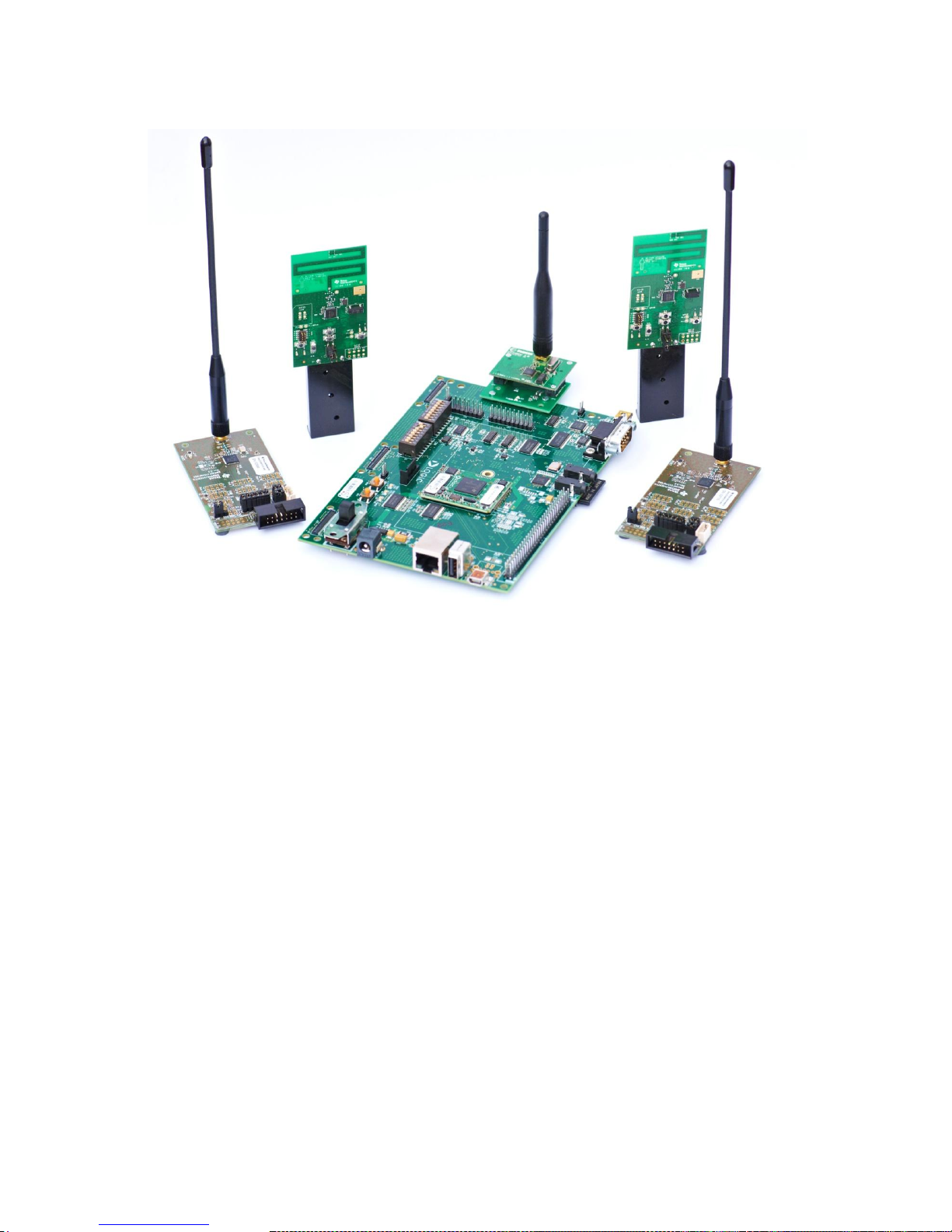
Figure 2. CC-6LOPWAN-DK-868 kit
1.2 What’s included in the kit?
2 CC1180DB nodes (CC1180 NWP plus MSP4305438A host MCU)
2 EM430F5137900 (CC430 SoC) nodes
1 OMAP-L138 based Edge Router Board (Gateway, running Linux)
1 Adapter board, for connection of CC1180EM to OMAP-L138 board
1 CC1180EM (radio interface to OMAP-L138 board)
MSP-FET430UIF Debugger, used to debug and download code to nodes.
Ethernet Cable (Crossover, for direct connection to PC)
RS-232 NULL modem cable (used for Linux debug console)
Power supply for OMAP-L138 board, incl. cables
USB cable for MSP-FET430UIF Debugger
Antennas, for 868/915 MHz band
Batteries (incl. holders for CC430 boards)
Quick Start Guide
Sensinode NodeView 2.0 Network Analyzer PC SW
Software application examples
Page 9
CC-6LOWPAN-DK-868
Page 9 of 61
2 Getting Started
This chapter gives the user a quick start to using the kit. The 6LoWPAN network is completely self
healing and self organizing. The only thing the user needs to do in order to get the network up and
running is to set up the Edge Router, verify that the Edge Router has Ethernet connection with IPv6
support and start it. When the NanoRouter application on the Edge Router board boots up, automatic
scripts configures the NanoRouter software and starts advertising the network over the radio
interface. For a more detailed procedure please see the Quick Start Guide [14].
If the pre-programmed nodes from the kit are powered up, they will automatically search for and join
to available network, allocate IPv6 addresses and are ready to go with no user input needed at all.
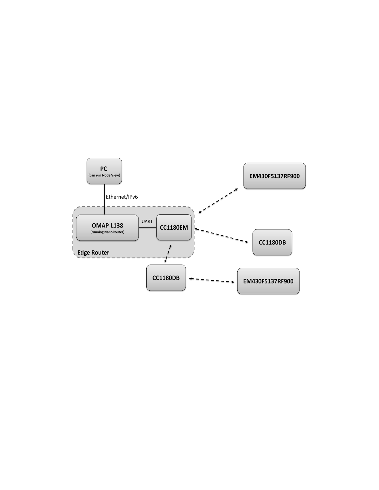
The following chapter provides more detailed information what happens behind the scenes. The
below picture describes an architectural overview for the complete system. Note that the 6LoWPAN
stack handles exactly which node connects to which node automatically, hence forming a fully
automatic 6LoWPAN network.
Figure 3. Kit System Overview
2.1 Setting up IPv6 on your PC
Most Internet hosts are still using IPv4 only a few are using the new IPv6 protocol. The Sensinode
NanoStack 2.0 is using IPv6, so you need to have your PC ready also. For Microsoft Windows Vista
and 7 IPv6 is supported natively. If you are running Windows XP, make sure that you have the
Service Pack 3 installed. In addition, when you have Windows XP Service Pack 3 installed, you also
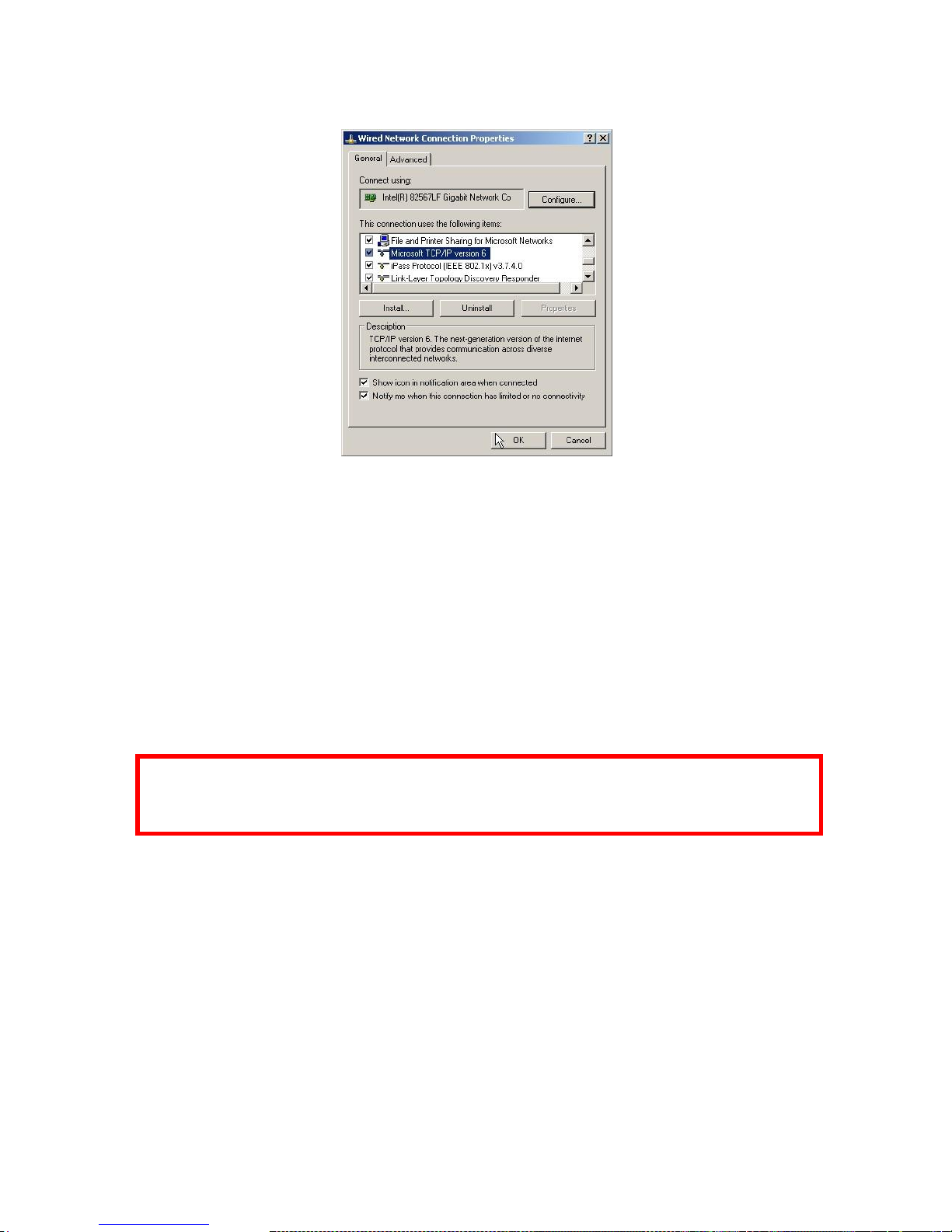
need to check to make sure that the IPv6 protocol is installed in your system. You can verify that this
is installed by looking at the properties of any Network Connection on your computer (Start Menu > Network Connections). As you see from the below screenshot, if you call the properties for any
connection, you should have an option called Internet Protocol Version 6 (TCP/IPv6).
Page 10
CC-6LOWPAN-DK-868
Page 10 of 61
Figure 4. IPv6 enabled for Windows XP
Follow the below steps to install IPv6 for Windows XP if you do not have it installed.
Open a command prompt and write:
ipv6 install
To be able to communicate with the devices using IPv6 your PC needs to be assigned an IPv6
address. Assigning an IPv6 address and a default route is described for Windows XP, Vista, 7 and for
Linux in the steps below.
Assign an IPv6 address to the PC using the command prompt (Run in administrator mode in Windows
7). This example adds the IPv6 address 2001::22 to your PC:
netsh interface ipv6 add address “Local Area Connection” 2001::22
Set up a default route using the command prompt: (Run in administrator mode in Windows 7)
netsh interface ipv6 add route ::/0 “Local Area Connection”
Note! You must change “Local Area Connection” to the actual name of the Ethernet connection you
want to use. You can get it from Windows Network Connections. The IPv6 address (2001::22 in this
example) has to be unique on your network.
For Linux the following commands to add IPv6 address and default route can be used:
ifconfig eth0 inet6 add 2001::22/64
route -A inet6 add 2001::/0 dev eth0
Note that some antivirus software blocks all incoming IPv6 traffic.
2.2 IPv6 and 6LoWPAN Basics
To fully benefit from the CC-6LOWPAN-DK-868 kit a basic understanding of both IPv6 and 6LoWPAN
is needed. This section makes the user familiar with basic IPv6 and 6LoWPAN technologies.
TI's third party Sensinode Ltd. 6LoWPAN solution provides an easy way of passing messages around
in a 6LoWPAN network, using a socket approach to both sending and receiving data as well as
controlling the network parameters. In small RF networks, i.e. a sensor network, sending data inside
the network is usually straight forward. Problems arise when one wants to send data to the internet or
intranet. This would normally include either specialized software on devices connected to the network,
Page 11

CC-6LOWPAN-DK-868
Page 11 of 61
or translating the RF protocol to a network protocol, i.e. using a proxy. CC-6LOWPAN-DK-868 is
therefore based on IPv6 and 6LoWPAN, eliminating such need for application layer gateways.
2.2.1 IPv6 Introduction
Internet Protocol (IP) is used in the world‟s largest networks. Nearly every desktop computer supports
IP, which makes IP ideal to use when one wants to hook up a wireless sensor network to a larger
backbone network. Setting up a wireless sensor network can even be managed by the IT department
on a company, without any knowledge of RF networks at all.
IP is not optimized for low-power, low-cost sensor networks. But since it's a very flexible protocol it
can fairly easy be adapted to make a perfect fit for a wireless sensor network, which is exactly what
6LoWPAN does.
2.2.1.1 Addressing
The most obvious difference between IPv4 and IPv6 is the number of supported addresses. IPv4
supports 232 addresses, while IPv6 supports 2
128
addresses.
A typical IPv6 address might look like this: 2001:0000:0000:0000:0000:00FF:FE00:0301. All
leading zeros can be omitted, leaving the address to look like: 2001:0:0:0:0:FF:FE00:301.
Finally zeros in the middle can be replaced by a double colon, leaving the address
to: 2001::FF:FE00:301
All IPv6 networks have a prefix. All devices in the same network have the same prefix. The prefix is
written like this: 2001:0:0:0:0:FF:FE00:301/64, meaning that the prefix is 64 bits long. Thus the
prefix for this example is: 2001:0000:0000:0000
Every interface also has a local link address associated with it. The link-local address is only valid
within the network and cannot be routed to another network. A link local address start with FE80::
2.2.2 6LoWPAN Introduction
Since the IPv6 header alone is 40 bytes, and the Maximum Transmission Unit (MTU) of IP is 1280
bytes, frames to be sent over a low power RF network based on IEEE 802.15.4 has to be
compressed in some way. IEEE 802.15.4 has a maximum packet size of 127 bytes, so a 40 byte IPv6
header would take up more than 30% of the packet. The 6LoWPAN adaptation layer bridges those
two technologies together, without the need of any application gateways.
Each node in a 6LoWPAN network has a unique IPv6 address, as described in the previous chapter.
In addition to the IPv6 address all nodes also has a unique 8 byte IEEE address. The IEEE address is
stored in flash memory of the devices. For CC430 based devices the IEEE address is stored on flash
address 0xFF70 (MSB on address 0xFF70). On the CC1180 the IEEE address is read and written
with a Sensinode bootloader utility called NanoBoot host. NanoBoot host is available for standard
Linux platforms and the OMAP platform. On all nodes in the CC-6LOWPAN-DK-868 the preloaded
IEEE address are printed on a sticker on each node.
2.3 Edge Router Bootstrap Prosess
The Edge Router board requires an Ethernet cable and main power. Also verify that the CC1180EM
radio module is properly connected to the OMAP J30 connector with the adapter board and has an
antenna. To start the Edge Router simply power up the board. On the board there is an automatic
script which will launch the NanoRouter 2.0 software during Linux kernel boot process. The time for
the Linux boot process is about 45 seconds. NanoRouter software status can be easily checked by
initiating a NodeView connection to the board IPv6 address, which is described in the next chapter.
2.4 NodeView 2.0
NodeView can be used to control and communicate with the NanoRouter software running on an
Edge Router. The NodeView software is a java based cross platform tool designed for 6LoWPAN
testing and evaluating purposes. When NodeView is started, it opens the „Router View‟ tab. The
„Router View‟ tab contains 'File' and 'Options' toolbars. To connect NodeView to an Edge Router
choose File->Add NanoRouter IPv6 from the menu.
Page 12
CC-6LOWPAN-DK-868
Page 12 of 61
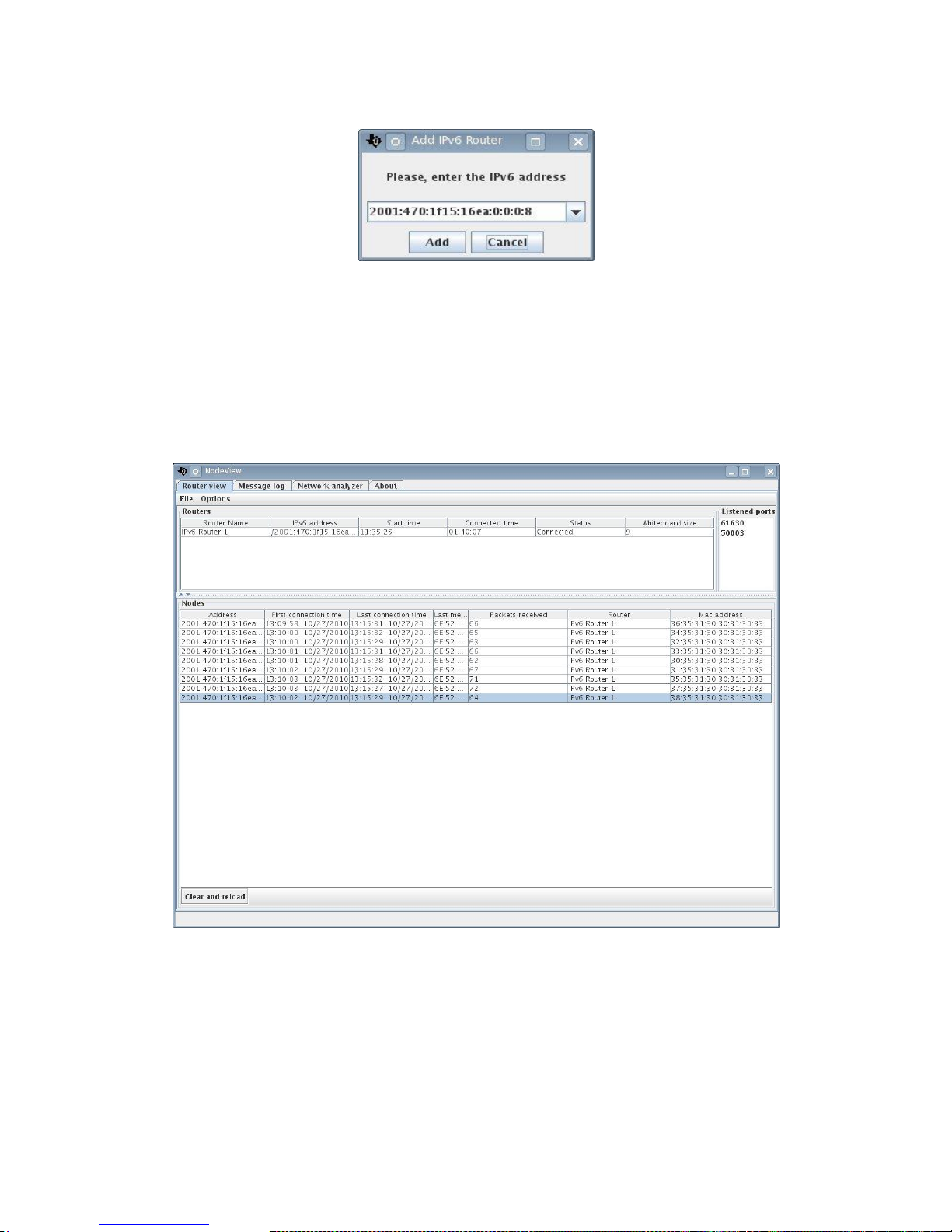
Figure 5. Adding an Edge Router.
The address must be given in a basic IPv6 format seen in the figure above. To connect to the
standard Edge Router delivered with the CC-6LOWPAN-DK-868 kit simply enter 2001::11. After the
Edge Router is added, the details can be seen from the NodeView „router View‟ tab if the connection
was successfully established. When a sensor node joins the network, it can be observed in the Nodes
list shown in Figure 2Figure 6. The list is updated based on the Edge Router whiteboard information
or by pressing 'Clear and Reload' button. The whiteboard of the Edge Router contains information of
all connected nodes.
Figure 6. NanoRouter Router View details.
As described earlier in this document nodes automatically scans for and joins available 6LoWPAN
networks. When a node has joined a network a Network Analyzer application is launched on the
node. The Network Analyzer application sends data about the network to the NodeView tool. The start
is trigged by a message from NodeView, the activation message is sent automatically every time
when the whiteboard information changes or when user press the „Clear and Reload‟ button.
Page 13
CC-6LOWPAN-DK-868
Page 13 of 61
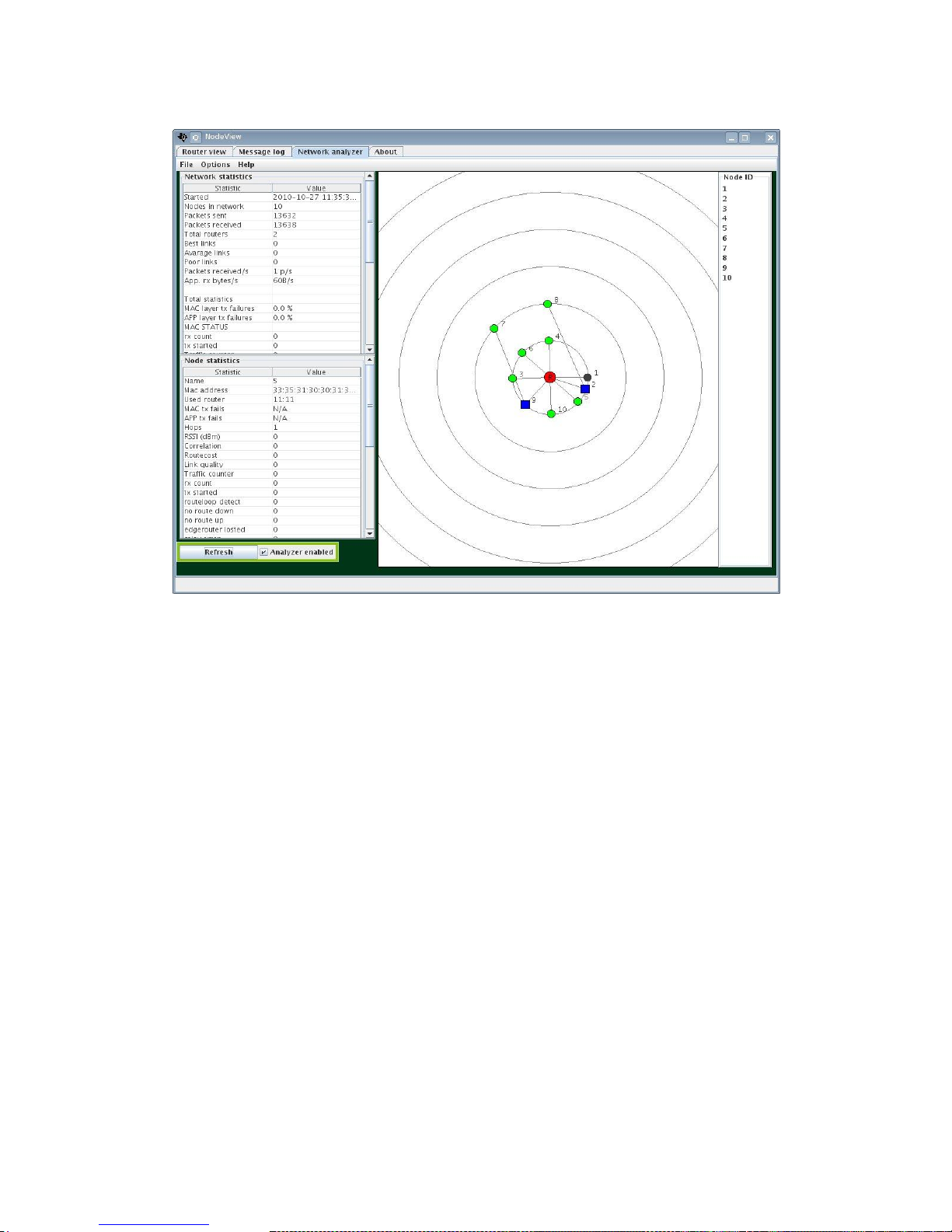
Figure 7. NodeView Network Analyzer tab.
In Figure 7, the green node indicates a normal node, while the blue color indicates a routing node.
The black/grey color indicates a node that has no longer connectivity to the NodeView. The red color
indicates a configured Edge Router. The circles describe a logical position of a node in the network in
hops. 'File', 'Options' and 'Help' contains useful information and configurations that can be useful. The
set Global Transmit Interval found in Options can be used to change how often the nodes are set to
send their network analyzer data to the Edge Router, the default value is 40s. Pay attention when
setting this value, since setting it too low in a large network can degrade the network overall
performance. One feature that can be useful when analyzing routing paths is the ability to have a
background image in NodeView. To enable this feature place your background image (must be in .jpg
format) in the same folder as NodeView, the go to Options->Use background. More information on
how to use NodeView 2.0 can be found in [10].
2.5 Network Analyzer Application
All sensor nodes come with a pre-programmed Network Analyzer firmware. The network analyzer
application is used to gather information about the network such as RSSI on different links, network
topology and application layer data traffic etc. This section describes behavior of the LEDs and
buttons that user may use on the nodes. The network analyzer application software for the nodes is
described in detail later in this document.
CC1180DB and CC430F5137 both have a green and a red led. The CC1180DB also has LEDs that
are controlled by the MSP4305438A host MCU. Radio LEDs (D1 and D2) are located in left bottom
corner when holding CC1180DB with jumpers and buttons pointing upwards. The CC1180 contains a
bootloader, Sensinode NanoBoot 1.0, and a NanoStack 2.0 Wireless Network Processor firmware.
The user can control which state (mode) that CC1180 is in, either bootloader mode or application
mode.
When the NanoBoot mode is chosen, both LEDs are on. The mode can be switched by pressing the
button S1. This will cause a falling edge interrupt to the CC1180 chip (grounding P1.2). Both LEDs will
be now disabled until a network connection is established (indicated with green LED). If the red LED
Page 14
CC-6LOWPAN-DK-868
Page 14 of 61
blinks with 1 second interval the network is disabled. The red LED also blink very rapidly during any
RF event but mainly remains inactive. Please note that the connection will not be established if the
MSP4305438A host MCU doesn‟t send a networking enable message or there is no active
NanoRouter available within the range with correct RF settings.
When the connection is established, green LED remains active and the red LED blinks on every RF
event.
Green LED active,
red LED disabled but
blinking
Red LED blinking with 1
second interval
Green LED inactive, red LED
blinking rapidly.
Both LEDs are
active
Network connection
established
Networking is not enabled
Scanning for network
Bootloader mode
Table 1. CC1180 controlled LED (D1 and D2) behavior.
Table 1 applies also for the CC430F5137 LEDs except for the bootloader LED usage, since there is
no NanoBoot 1.0 in use in CC430F5137). The MSP4305438A host MCU has a Network Analyzer
application programmed by default as describe earlier in this document. The RSSI for the node is
displayed using the LEDs. The LED control of the Network Analyzer application is defined in Table 2.
Red LED
toggling with
1 second
interval
Both LEDs
disabled
Green
LED
active, red
LED
disabled
Both LEDs remains active
Red LED remains active,
green LED disabled
3 concurrent
reply
messages
missed or
Analyzer is not
activated
Reply
message
measured
RSSI level
above -40
dBm.
Reply
message
measured
RSSI level
between 40 and -65
dBm
Reply message measured
RSSI level between -65 and 90 dBm.
RSSI reading below -90 dBm.
Table 2. MSP4305438A controlled LED (D3 and D4) behavior.
3 Software
Sensinode NanoStack 2.0 lite operating system core is event based, all the peripherals such as
timers, trigger events are executed in the main program. Interrupt service routines are used by
hardware drivers which may trigger events.
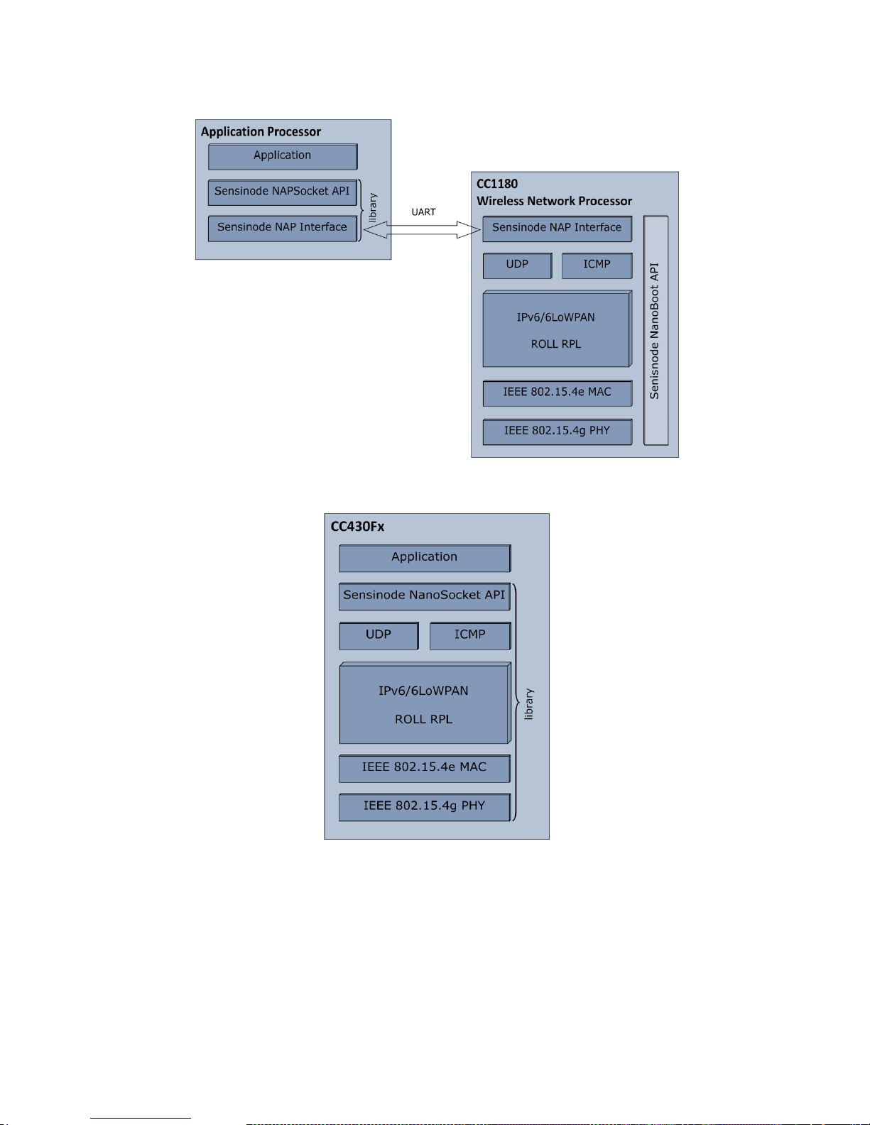
3.1 Sensinode NAPSocket and NanoSocket interface
There are, as described earlier, two different APIs for using Sensinode NanoStack 2.0 lite. Network
Processor (NAPSocket API [12]) and the library model (NanoSocket API [8]) provide easy-to-use
interfaces. NanoStack 2.0 lite networking must be initialized properly, networking is off by default.
User is provided an interface which allows enabling of networking; e.g. polling connectivity and
configuring the RF interface setup for user needs. For the Network Processor, NAPSocket library [12]
is an interface library running on a host MCU controlling the Network Processor (CC1180). The library
model of NanoStack 2.0 lite uses a function call interface which allows direct access to configure
networking features as well as other configurations, e.g. RF configuration. This interface system is
called NanoSocket API [8]. NanoSocket API is linked into user IAR application project and it contains
a .lib file of NanoStack 2.0 lite and a few header files. Both interfaces encapsulate UDP
communication into a simple socket system, making RF easy! The Sensinode NAPSocket and
NanoSocket APIs are described in detail below.
Page 15
CC-6LOWPAN-DK-868
Page 15 of 61
Figure 8. Stack overview CC1180 based system, using NAPSocket API
Figure 9. Stack Overview CC430 based system, using NanoSocket API
3.2 Sensinode NanoStack 2.0 lite
Sensinode NanoStack 2.0 lite is an embedded operating system and a 6LoWPAN protocol stack
designed especially for low power and cheap wireless sensor devices.
The protocol stack is designed to comply with a set of standards mostly provided by IETF 6LoWPAN
working group. Table 3 describes the layer structure of the protocol stack and the used standards for
each protocol layer.
Page 16

CC-6LOWPAN-DK-868
Page 16 of 61
Layer
Standard
Description
PHY
802.15.4g [4]
Link layer communication
-GFSK modulation
-FHSS support
-Single band in EU
MAC
802.15.4e [5]
Link layer communication
-Addressing modes (16 bit
addressing mode)
-AES-128 bit CCM* support
IP
draft-ietf-6lowpan-hc-13 [1]
Network layer communication,
routing
-Addressing modes (128 bit,
multicast group 2, link local)
Neighbour Discovery
draft-ietf-6lowpan-nd-13 [2]
Network layer communication,
address registration, network
scan. Neighbour resolution.
Routing method
Draft-ietf-roll-rpl-13 [3]
Network layer communication,
coordinator controlled routing.
Table 3. Sensinode 6LoWPAN Stack Layer Definitions.
3.2.1 Bootstrap process
When a node is powered up and set to search for network, it activates the MAC and PHY radio
operations automatically, providing a fully automatic bootstrap process.
3.2.2 Synchronization
All nodes must synchronize to a simple 6LoWPAN Edge Router since the radio PHY supports
frequency hopping system. When the synchronization is established, each node will start hopping on
the predefined channels. Each node remains in a channel for 350 ms, this time period is called an
active period. After each active period, a new channel is chosen and nodes remain in a guard period
for 50ms. During that period, radio receivers are disabled and no communication is performed. Each
50ms slot in the active period and the guard period is called a superframe. Each superframe consists
of 330 microsecond slots. Each superframe causes an interrupt for the radio module. This interrupt is
served by a crystal; the crystal must follow tolerances stated in the respective datasheet in order to
keep up the synchronization. Note that the synchronization is established even if the system is of
single channel type. During the active period, RF receiver is active and MCU is running. (In
CC430F5137 CPU sleeps if no other operations are performed in order to keep the power
consumption at a minimum).
The synchronization process is described here. First, a powered and activated node scans for the
beacon by broadcasting a beacon request periodically. Each node which is already joined to the
network will reply with a unicast beacon to the originator of the beacon requests. The beacon contains
timing information of the superframe. The beacon payload is described in Table 4.
Byte 1 2 3 4
5
Value
'S'
'F'
Remaining slots
in superframe
Superframe ID
Next channel
table index
Table 4. Beacon payload.
Here, the 'S' and the 'F' are header bytes to discard beacons of other systems. The remaining slots
field in the superframe message describe how many 330 us slots are left in a current superframe. The
superframe ID describes the number of the current superframe. Superframes are numbered from 0 to
7; where 1 to 7 is the active period superframes and superframe 0 indicates the guard period.
Beacons and beacon requests are built according to IEEE802.15.4e specification [5]. After
synchronization is performed, it is updated with ~10 second interval by sending unicast beacon
request to the node that responded to the beacon.
Page 17

CC-6LOWPAN-DK-868
Page 17 of 61
3.2.3 Neighbour Discovery and Router Solicitation
When a node is synchronized, the ICMP (Internet Control Message Protocol) layer is activated. The
ICMP layer scans for suitable routing nodes or Edge Routers by broadcasting a Router Solicitation
(RS) message. On reception of a RS, a routing node responds by sending a link local (unicast) Router
Advertisement (RA) to the scanning node.
On reception of a RA, the joining node receives the IPv6 prefix of the network. The prefix is used to
communicate within a simple 6LoWPAN network. Here, the prefix is defined to be 8 first bytes of the
IPv6 address that the NanoRouter advertises. After the prefix information is solicited, the node sends
a Neighbour Solicitation (NS) message. The NS message is used to solicit neighbour information of
the network. Here, a neighbour cache size is zero and therefore contains no entries. The NS also
contains a header field to register an allocated 16-bit short address. As a response to the NS, a
Neighbour Advertisement (NA) is sent. The NA message contains information of advertising node and
status fields if the address allocation was successfully performed.
The NS is sent first to a routing node which then delivers it to the Edge Router using RPL routing, if
the scanning node cannot reach the Edge Router directly. The NA message is sent from the Edge
Router to the routing node, which then sends it to the registrating node by using the link local unicast.
More detailed information can be found from Draft-ietf-6lowpan-nd-13 (draft-ietf-6lowpan-nd-13) [2].
3.2.3.1 Fixed packet formats
In order to achieve a very lightweight 6LoWPAN stack, some packet formats need to be fixed to avoid
unnecessary packet processing. In this section fixed packet formats are described. Table 5 describes
fixed packet formats of Neighbour Discovery messages.
Message
Format
Router Solicitation (RS)
SLLAO
Router Advertisement (RA)
PIO, ABRO, SLLAO
Neighbour Solicitation (NS)
ARO, SLLAO
Neighbour Advertisement (NA)
ARO, SLLAO
Table 5. Fixed Neighbor Discovery packet formats.
If other packet formats of Neighbour Discovery messages are received, they are discarded silently.
Detailed explanation of SLLAO, PIO, ABRO and ARO can be found from [2].
3.2.4 RPL: IPv6 Routing Protocol for Low power and Lossy Networks
In order to achieve a lightweight 6LoWPAN stack, routing is based on RPL control messages (DIS,
DIO, DAO and DAO-ACK). The routing is coordinated by the NanoRouter 2.0 software running on the
Edge Router, which keeps record of routing tables as well as whiteboards over time.
Nodes form topological paths extending from the access point. Each node „knows‟ their RPL parent.
Each node allows an unlimited amount of child nodes, but only one child may continue routing. This is
controlled by RPL poisoning and by sharing DIO message information required for routing. Each node
is registered into the Edge Router (NS, DAO), so the Edge Router can form a whole path into a single
node by summarizing all the registration data. Finally, the Edge Router knows the destination
address, path and depth in a network and therefore is able to route data to the destination. Forwarded
messages are also having a flag (RPL hop-by-hop option header) which indicates the direction of
forwarded data (up and down).
In routing systems where flow paths are used, each „knot‟-node can become a problem. As a flow
spreads into separate flows, routing becomes impossible. Each node can have only one routing child,
but unlimited amount of non-routing child nodes. Therefore routing is allowed only in a node which
was connected to a routing node as the first child. This logic is controlled by a timer, by keeping the
first child addressing information in memory and by restricting routing using RPL control message
(DIO).
Draft-ietf-roll-rpl-13 [3] defines the used routing protocol. It contains a few ICMP layer messages
called RPL control messages. These messages contain information of routing nodes and hosts. The
information is gathered to the Edge Router and routing configurations are sent all over the simple
6LoWPAN network. Table 6 illustrates a basic description of each message type.
Page 18
CC-6LOWPAN-DK-868
Page 18 of 61
Message type
Description
Addressing options
DIS
Used to scan for RPL DODAG.
Multicast, unicast
DIO
Used to advertise RPL DODAG.
Multicast, unicast
DAO
Contains routing information from source to
the next hop parent.
Unicast
DAO-ACK
Acknowledge message for DAO.
Unicast
Table 6. RPL control messages
When the node has accomplished Neighbour Discovery, the RPL routing protocol takes place. A
joining node scans for a Destination Oriented Directed Acyclic Graph (DODAG) Information Object
(DIO) by broadcasting a DODAG Information Solicitation (DIS) message. When a routing node
receives the DIS message, it sends the DIO as a response. The DIO may, or may not, contain
DODAG information. All details of this functionality are described in [3].
The DIO message also contains address information of the parent and a RPL root which is the Edge
Router. On reception of the DIO, a Destination Advertisement Object (DAO) is sent to the RPL root
after a predefined time. The DAO contains route information from the RPL host to the RPL parent.
Here, this information represents one logical interconnection within the simple 6LoWPAN network.
When the root receives the DAO, it gathers route information of the DAOs to a routing table. The
routing table can be used to build a whole path from the root to the destination node. This allows the
root to send data to any registered and joined node within a RPL DODAG. As a response to the DAO,
a DAO-ack is sent if requested.
In order to achieve a lightweight 6LoWPAN stack, P2P data (data going from node to node) has to be
delivered to the Edge Router and then routed from the Edge Router to the destination node. More
detailed information of each packet format can be found from [3]. It is however possible to send data
directly from one node to another by using the multicast feature, given that the nodes are within the
same physical RF range.
3.2.4.1 Fixed packet formats
Draft-ietf-roll-rpl-13 [3] defines multiple formats for RPL control messages and their options. Table 7
describes fixed packet formats for each RPL control message.
RPL control message
Options
DIS
No options
DIO
DODAG configuration, metric container or only metric
container
DAO
RPL target, transit information
DAO-ack
No options
Table 7. Fixed formats of RPL control messages.
Any other formats of RPL control messages are discarded silently.
3.2.4.2 DODAG configuration option
This CC-6LOWPAN-DK-868 kit uses a custom RPL objective function, please see [3] for more
information. Here, an Objective Code Point (defined in a DODAG configuration in [3]) is defined to be:
MSB byte
LSB Byte
's'
'n'
Table 8. RPL Objective Code Point.
Page 19
CC-6LOWPAN-DK-868
Page 19 of 61
The Objective Code Point indicates a used objective function. The Objective Function requires a
metric container. The metric container has the following format:
Byte 1
Byte 2
Byte 3
Byte 3
Type = 2
Length = 2
's'
Hop count
Table 9. RPL Metric container format.
The metric container must be included within a DIO and if it not exists, the DIO is discarded silently. A
node that doesn't receive DODAG configuration must advertise its rank as INFINITE_RANK (0xffff).
3.2.4.3 Sensinode custom Objective Function
The used Objective Function is based on a link quality metric where the received signal strength
indicator is graded from 1 to 8, where 1 is the best possible link and 8 is the worst link. The rank used
in RPL control messages is then calculated on the reception of a DIO message. The calculated link
quality grade is added to the received rank. The calculated rank is then divided by a hop count within
the metric container and is compared to the current rank divided with current hop count. If the new
rank is smaller than the old rank, a topology change is made. Therefore a DODAG configuration
defines minimal rank increase of 255*1 and maximum rank increase of 8*255. For platforms not
supporting RSSI calculation, default rank increase of 3 can be used. Table 10 summarizes these
definitions.
Definition
Value
Minimum rank increase
255*1
Maximum rank increase
255*8
Default rank increase
255*3
Table 10. DODAG configuration parameters.
A more detailed explanation of these parameters can be read from [3]
3.2.5 Periodic processes
This section describes the periodic messaging within a simple 6LoWPAN network. In order to update
the routing information, the RPL protocol sends messages periodically to maintain and update routes.
The period is mainly controlled by Edge Router (NanoRouter) but may change dynamically due to RF
events within a network.
In order to verify the connectivity and avoid duplicate address allocation, also the Neighbour
Discovery process is performed periodically. The period may change depending on failure events
within a network.
The synchronization is also updated periodically as explained in 3.2.2. Timings may also change due
to RF errors and accepted beacons.
3.2.6 Error situations
Users of the kit need to be aware of and fully understand the limits of the radio range of the used
devices. If the node doesn't have a network within its radio range, it is not able to join the network. If
default firmware (Network Analyzer application) are used, the LEDs will indicate (via RSSI) this kind of
a communication problem as explained in Table 1.
As the routes are maintained based on periodic scans and advertisements, the network do not
support a high grade of mobility. There will be communication losses if a node has been joined to an
existing network but then is moved to a different location within the network. This is due to the fact
that the nodes cannot realize the change in topology very fast. However, the network is able to do
self-healing in these situations by listening to advertisements all the time.
Page 20

CC-6LOWPAN-DK-868
Page 20 of 61
3.3 CC-6LOWPAN-DK-868 Software Projects
Included in the kit are example projects to be used with IAR Embedded Workbench. This section
describes the setup, use of, and installation of those projects.
3.3.1 IDE installation
The projects included in the kit are for the IAR Embedded Workbench IDE 5.20 for MSP. It is possible
to use the "Kick-start" version of the IAR Embedded Workbench to build the application examples for
CC1180DB. The IAR “Kick-start” version allows the user to build applications not exceeding 8kB. The
demo application (Network Analyzer) for CC1180DB in the kit is using the NAPSocket library, and the
build size is about 4kB of Flash and 2kB of RAM (including the NAPSocket library).
To be able to build a CC430 application one must use the full version of IAR Embedded Workbench,
due to the size of the 6LoWPAN CC430 NanoSocket library. The build size for the CC430 demo
application (including 6LoWPAN stack) is about 19kB of Flash and 3kB of RAM. This leaves 13kB of
flash and about 1kB of RAM to the user application.
For software development and modification of the preprogrammed firmware (Network Analyzer) the
following steps are needed:
1. Install IAR Embedded Workbench for MSP, all versions can be found here: IAR Embedded
Workbench
2. Download the CC-6LOWPAN-DK-868 Application Example zip files from
http://www.ti.com/6lowpan and unzip the files.
3. Download the NAP Socket library source from http://www.ti.com/6lowpan; this is needed to
get the .lib file that the CC1180 example application is using. It is also needed if you want to
run/port the application in/to another host MCU.
Make sure to extract the NAP Socket library and Example Application into the same folder, in order to
not have to change the settings in the IAR projects.
For more information on the different IDE options and details please visit http://www.iar.com
The examples are all configured as IAR workspaces, one workspace for CC430 and one for
MSP430F45438A (to be used on the CC1180DB). The workspace for CC430 is called
CC430NetworkAnalyzer.eww and the workspace for MSP430 (for use on the CC1180DB) is called
NanoHOEX.eww.
The files are organized into folders corresponding to their location in the file structure, e.g.:
Libraries - this contains used library file. Either CC430 NanoSocket library or Sensinode NAP
Socket library for MSP430 (for CC1180DB).
Applications - the sample applications.
Platform - this contains miscellaneous utilities, such as ADC driver for temperature/battery
level measurements.
IAR automatically creates an additional directory, Output, that contains any debug or list files.
The project configurations are all fairly simple to ease the transition to other platforms. Changes to the
default project configuration are the following (can be found under project Options-> Project: Options)
CC430 project:
General Options: Target - change Device to CC430F5137. Library Configuration - CLIB.
Library options - Change to Large Printf formatter. Change to Large Scanf formatter.
Stack/Heap - Override default and set Stack size: 256, Data16 heap size: 256.
C/C++ Compiler: Language tick multifile comp. Preprocessor - Under "Additional include
directories" the relative paths for all files are added. Otherwise IAR will display a warning if
the project directory changes, since IAR by default uses absolute paths in its project
configuration. Under Defined symbols: add NS_DEBUG=1 (if debug interface shall be
enabled) and MSPCORETYPE=5137.
Page 21

CC-6LOWPAN-DK-868
Page 21 of 61
Linker: Extra Output - Check Generate Extra Output. Output file: Check override default and
name the file *.hex
MSP430 project:
General Options: Target - change Device to MSP430F5438A. Library Configuration - CLIB.
Stack/Heap - Override default and set Stack size: 512, Data16 heap size: 512.
C/C++ Compiler: Preprocessor : Under "Additional include directories" the relative paths for
all files are added. Otherwise IAR will display a warning if the project directory changes, since
IAR by default uses absolute paths in its project configuration. Defined symbols: USE_IAR=1
Linker: Extra Output: Check Generate Extra Output. Output file: Check override default and
name the file *.hex
3.3.2 NanoHost Example (Network Analyzer)
The nodes included in the kit come preloaded with an application to monitor the 6LoWPAN network
topology and to provide link quality data to the user. The Network Analyzer Demo Application on the
nodes is used in conjunction with the PC software NodeView 2.0 to monitor and analyze the
6LoWPAN network. NodeView 2.0 software on the PC sends out a message containing information to
the nodes on how often they are supposed to report their status to NodeView 2.0. This value is set in
NodeView 2.0 and can be changed under "Network Analyzer tab -> Options -> Set Global Interval"
Default is 40s.
The Network Analyzer program sequence is this:
1. Node View sends out a "start" message to the connected nodes.
2. Nodes reply with a message containing data such as; short address, parent address, number
of hops away from Edge Router and RF signal info. The payload length of this packet is 31
Bytes.
3. Node View sends an ACK message to the node. The payload length of this packet is 9 Bytes.
4. Data is shown in Node View.
5. Nodes keep sending data to Node View with the defined interval.
As is described in chapter 3.4 the NanoHost example project uses the Sensinode NAPSocket library
as a parser library to handle the communication between the host MCU (MSP430F5438A) and the
network processor (CC1180) on the CC1180DB board.
The files in the IAR project for CC1180 have the following file structure:
Applications - The network Analyzer application source files.
Libraries - The NAP Socket library file, which is the API to NAPSocket.
Platform - Contains platform (i.e. MSP430F5438A) specific files.
Output - The output .hex file is put here.
You'll also notice that the IAR project has the includes defined in Project Options. These definitions
($PROJ_DIR$/something etc) are there to make the examples portable since IAR by default uses
absolute paths. Otherwise when you open the examples you would get an error if your file structure
doesn‟t exactly match the provided.
The NanoHost example is described in detail in [11].
3.3.2.1 Getting started with application development for CC1180 (NAPSocket)
1. Open IAR Embedded Workbench for MSP
2. Open workspace NanoHOEX.eww
3. Connect CC1180DB via MSP-FET430UIF Debugger to your PC
4. Select Debug or Release, depending on if you want to debug or just download the hex file to
CC1180DB (MSP430F5438A) from the workspace panel.
5. Click Download and Debug in the menu, or use Ctrl-D
Page 22

CC-6LOWPAN-DK-868
Page 22 of 61
Figure 10. NanoHost Example project
3.3.3 NAPSocket Library
The NAPSocket library is provided in source code in order to be able to port the library to other
platforms. The NanoHost example application is using the NAPSocket library to send and receive
data from the CC1180 Network Processor.
The NAPSocket library is described in detail in the Sensinode document [12].
Figure 11. NAPSocket library project
3.3.4 CC430F5137 Library Model (Network Analyzer)
The program flow and logic are exactly the same as for the CC1180DB version described in 3.3.2.
The files in the IAR project for CC430 have the following file structure:
main.c- The Network Analyzer application source file.
*.lib - The NanoSocket library file, which is the API to NanoSocket.
Output - The output .hex file is put here.
You'll also notice that the IAR project has the include files defined in Project Options. These
definitions ($PROJ_DIR$/something etc) are there to make the examples portable since IAR by
default uses absolute paths. Otherwise when you open the examples you would get an error if your
file structure doesn‟t exactly match the provided.
Page 23

CC-6LOWPAN-DK-868
Page 23 of 61
Figure 12. NanoSocket Example project
3.3.4.1 MCU Resources in use by NanoStack 2.0 lite on CC430
The following hardware resources are occupied by the library CC430F5137_NanoStack20lite and
therefore not available for user application.
All timer modules
Watchdog
DMA interrupt
The UART is occupied if application is compiled with NS_DEBUG defined (CC430 provides
one UART, UCA0)
CC1101 radio interface
LEDS according to EM430F5137RF900 schematic are in use. However,
DISABLE_AUTOMATIC_LEDS() function can be used to allow user defined led functionality
AES engine and CRC engine
Unified clock system:
UCSCTL4 |= SELA_0;
UCSCTL4 |= SELS_5; // Set SMCLK = XT2CLK (26MHz same crystal as radio core)
UCSCTL4 |= SELM_5; // Set MCLK = XT2CLK (26MHz same crystal as radio core)
UCSCTL6 &= ~XT2OFF; // Set XT2CLK on
UCSCTL5 |= DIVS_1; // SMCLK-divider = 2 (26/2 MHz)
Core voltage level must be 3.
Application must not disable interrupts.
3.3.4.2 NanoSocket Debug Interface
The NanoSocket library provides a debug interface that can print out debug information on the CC430
UART to display on a terminal program on a PC. The NanoSocket Debug Interface is enabled by
compiling the CC430 project with NS_DEBUG enabled, see Figure 13. By not including the
NS_DEBUG during compile time the UART is free to use for the user application. The UART settings
for the Debug Interface are 115200, 8N1, no flow control.
Figure 13. Enabling the NanoSocket Debug Interface
An example of a debug printout is shown below.
Page 24

CC-6LOWPAN-DK-868
Page 24 of 61
APP: RF MAC is:
0x00:0x12:0x4B:0x00:0x00:0x0E:0x20:0x17
APP: INIT OK!
Looking for access point...
Connection information:
-----------------------
HWaddr:00124B00000E2017
inet6: 2001000000000000000000FFFE004227
parent:2001000000000000000000FFFE00D734
Access point:2001000000000000000000FFFE000000
hop: 2
-----------------------
Hello world!
It is also possible to send data to the CC430 node via the debug interface. Sending „h‟ to the CC430
Network Analyzer example application will print out “Hello World!” on the debug interface. For more
information and details on using the debug interface see the Network Analyzer example application
IAR project for CC430.
3.3.4.3 Getting started with application development for CC430 (NanoSocket)
1. Open IAR Embedded Workbench for MSP
2. Open workspace CC430NetworkAnalyzer.eww
3. Connect EM430F5137RF900 via MSP-FET430UIF Debugger to your PC
4. Select Debug or Release, depending on if you want to debug or just download the hex file to the
CC430 based board from the workspace panel.
5. Click Download and Debug in the menu, or use Ctrl-D
6. Click start, or F5.
Note: Debug using breakpoints when running a 6LoWPAN network is not possible, since the
6LoWPAN stack is implemented as a real time OS and the nodes are time synchronized. However
debug can be used before stack is initialized. Use the debug interface described in 3.3.4.2 to print
debug information when NanoStack is running.
3.3.5 Programming the boards
This section describes two alternatives on how to program the different boards. The boards can either
be programmed directly from IAR EW, alternatively if the hex files already exist, the TI Flash
Programmer tool can be used. In either case the node (either CC430 or CC1180DB) will have to be
connected to the PC via the MSP-FET430UIF Debugger with a USB connection. The following
section describes the steps needed to build the projects and download hex files to the hardware using
IAR EW.
3.3.5.1 IAR Embedded Workbench (Can only be used on CC1180DB)
1. Open IAR Embedded Workbench for MSP
2. Open the workspace file NanoHOEX.eww with IAR. This file is found in the subfolder
\Sources in the folder where you unpacked the CC-6LOWPAN-DK-868 Applications
Examples zip file.
3. There are two different configurations for the IAR project; Release and Debug. Use Debug for
debugging your source code and release to build smaller hex files without debug information
in it.
4. Select Project->Rebuild All. This will perform a full rebuild on the selected project.
5. Connect the CC1180DB board to program to the MSP-FET430UIF Debugger.
Page 25

CC-6LOWPAN-DK-868
Page 25 of 61
6. Connect the MSP-FET430UIF Debugger to the PC with a USB cable.
7. Select Project->Debug to program the MSP430 (application (host) processor on the
CC1180DB).
8. Stop the debugger by selecting Debug -> Stop Debugging.
9. Repeat steps 7 to 8 to program additional boards.
3.3.5.2 TI Smart RF Flash Programmer (Can be used on CC430 and CC1180 host MCU)
This procedure is needed since all nodes have an IEEE (i.e. MAC) address that needs to be unique
within the 6LoWPAN network. All CC1180 chips has that pre-programmed from TI, however for the
CC430 the nodes have the IEEE address stored in the Flash memory at location 0xFF70. Thus the
IEEE address has to be written to that flash address in order for the nodes to be able to function.
There are several ways of doing this; one way is to use this line of code in the CC430 software:
__root __code const uint8_t hard_coded_mac[8] @ 0xff70 = {0x01, 0x02, 0x03,
0x04, 0x05, 0x06, 0x07, 0x08};
This will place the value 0x0102030405060708 at flash address 0xFF70.
Another (more complex) way is to modify the .hex file before it is downloaded to flash on CC430. This
is described here, this example adds the IEEE address 00:12:4B:00:00:0E:20:16 to the hex file. You
will have to change the IEEE address to your node specific address, for the kit the IEEE address can
be found on a sticker on the node.
Open CC430NetworkAnalyzer.hex e.g. in Notepad.
Insert :08FF700000124B00000E2016E8 on the 5th line from the bottom. Do not erase any
line, simple add this line to the hex file.
Save file as e.g. CC430NetworkAnalyzer_N2016.hex and close Notepad.
Connect the EM-CC430F5137-900 board to MSP-FET430UIF Debugger
Use Smart RF Flash Programmer to download the hex file
CC430NetworkAnalyzer_N2016.hex to the CC430 board.
To add the address 00:12:4B:00:00:0E:17 you would add the line:
:08FF700000124B00000E2017E7
Hint; if you increase the IEEE address by one you decrease the CRC (last byte) with one.
The hex file is constructed like this:
:08FF700000124B00000E2017E7
Start code
Byte count
Address
Record type
Data (in this case the IEEE/MAC address)
CRC
3.4 Sensinode NAPSocket API
This API is used on a host processor that communicates with the CC1180 network processor via a
UART interface. The main goal for the NAPSocket library is to provide a simple way for users to work
with NanoStack 2.0 lite CC1180 Network Processor. The user is able to use NAP protocol
configuration commands via a simple command interface. Since the NAP protocol also provides
transmissions of 6LoWPAN messages, the interface introduces a socket interface to be use with the
library. The user is able to send data packets through the socket interface the library converts
messages to the NAP protocol format. The library is a parser library, which means that it‟s the user‟s
responsibility to create suitable drivers and operating system for the chosen platform.
Page 26

CC-6LOWPAN-DK-868
Page 26 of 61
All details on the NAPSocket API are found in the Sensinode documentation [12].
Figure 14. Sensinode NAPSocket library
3.4.1 Sensinode NAP Protocol API
The Sensinode NAP interface protocol is used to access the functionality provided by the CC1180
Network Processor with Sensinode NanoStack 2.0 lite. The NAP protocol has been specifically
designed to be used over UART. The NAP protocol has been designed to be an easy-to-parse, lowoverhead serial protocol that has enough flexibility and extendibility for the Sensinode NanoStack 2.0
Network Processors. The potentially limited serial port data rates have imposed the need for a very
low overhead compared to the actual payload data. The NAP protocol defines two main types of
packets
· Config for all configuration messages (request and replies) and status queries & answers
· Data for all data communication
The Sensinode NAP protocol can be used directly without NAPSocket library to communicate with the
CC1180.
All information about the NAP Protocol API can be found in the Sensinode document [9].
3.5 Sensinode NanoSocket API
This API is used on a CC430 device running both the Sensinode 6LoWPAN stack and the user
application. The user is able to use configuration commands via a simple command interface. A
socket interface provides transmissions of 6LoWPAN messages. The library contains a sophisticated
operating system called NanoStack 2.0, which means that user doesn't need to implement drivers and
operating system for the chosen platform.
Page 27

CC-6LOWPAN-DK-868
Page 27 of 61
Figure 15. Sensinode NanoSocket API
The NanoSocket API is described in the Sensinode document [8].
3.6 Sensinode RF Dynamic Configuration API
To change RF configuration settings the Dynamic RF Configuration API is used. The API is basically
the same both for CC1180 NWP and for CC430 SOC, with minor differences.
Using the API one can make set the following:
Data rate; 50, 100, 150 and 200kbit/s
Channel spacing, Frequency spacing between two adjacent channels can be set to 200 or
400 kHz. Only used in FHSS systems.
Modulation Index, this setting changes the deviation used in GFSK modulation. Possible
values for the modulation Index is 0.5 and 1. The deviation is calculated by:
Base Frequency, for single band system this sets the used channel. For multi band (FHSS)
systems this sets the leftmost frequency.
TX Power level, PA_TABLE0 setting for CC1180 and CC430.
RX Attenuation, set RX attenuation levels in order to avoid saturation.
Frequency hopping, Enabled / Disable FHSS. Enables 50 channels FHSS mode. In FHSS
mode the base frequency sets the lowest frequency used (leftmost). If FHSS is disabled the
base frequency sets the used operating channel.
The RF Dynamic Configuration API is described in [13].
3.6.1 NanoSocket
This section describes how to use the Dynamic RF Configuration API in the NanoSocket on CC430
nodes.
//default settings for RF interface
Page 28

CC-6LOWPAN-DK-868
Page 28 of 61
static rf_conf_settings_t rf_configurations = {DATA_RATE_50, CHANNEL_SPACING_200,
MODULATION_INDEX_10, 0x21,0x65,0x6a, 0xc3, RX_ATTENUATION_0dbm};
rf_conf_set_params(&rf_configurations); //Set RF Config for CC430
The data rate parameter can have the following values: DATA_RATE_50, DATA_RATE_100, DATA_RATE_150
and DATA_RATE_200.
The channel spacing parameter can be either CHANNEL_SPACING_200 or CHANNEL_SPACING_400.
Modulation index parameter can be set to MODULATION_INDEX_10 or MODULATION_INDEX_05.
The values 0x21, 0x65, 0x6a in the above example, give the used frequency. The values correspond
to the FREQ2, FREQ1 and FREQ0 registers. The values can be obtained from the SmartRF Studio
tool, see ti.com for download.
The value 0xc3 in the example above, gives the output power. 0xc3 corresponds to 10dBm output
power, use values from data sheet for CC430.
In order to enable FHSS, the function net_enable_fhss() is called. Please see CC430F5137 Library
Model Network Analyzer Example project for details.
3.6.2 NAPSocket
This section describes how to use the Dynamic RF Configuration API in the NanoSocket on CC1180
nodes.
//rf configurations to load...
static rf_conf_settings_t rf_config = {DATA_RATE_50, CHANNEL_SPACING_200, MODULATION_INDEX_10,
0x21, 0x65, 0x6a, 0xc2, RX_ATTENUATION_0dbm, FHSS_DISABLED};
rf_conf_set_params(&rf_config);
Please see NanoSocket section for a complete description of the API. The only difference is that
FHSS can be enabled and disabled using the FHSS_DISABLED parameter. See the CC1110 data sheet
SWRS033.pdf, for configuration of the output power parameter.
3.6.3 Node View 2.0
This section describes how to change RF Configurations for the Edge Router using the Sensinode
Node View 2.0 tool.
1. Double click on the Router whose RF configuration you want to change in the Router View
tab.
2. Click on the button “Remove Interface”
3. Click on the button “Create Interface”
4. Fill in the setting you want and click “Add”
Figure 16. Setting RF Configuration on Edge Router
The NanoRouter software running on the Edge Router saves the RF configuration settings in the file
/last/configFiles/rf_configuration_ttyS1.conf
Page 29

CC-6LOWPAN-DK-868
Page 29 of 61
An example of this file is shown below.
root@da850-omapl138-evm:~/last/configFiles# cat rf_configuration_ttyS1.conf
Interface Id=0
Crystal=26
Data rate=50
Channel spacing=200
Modulation index=10
Base frequency=2180332
TX power=194
RX attenuation=0
Freq. hopping=0
3.7 Sensinode NanoBoot API
Loading the Sensinode NanoStack 2.0 lite 6LoWPAN stack to CC1180 is performed using Sensinode
NanoBoot API. The CC1180 contains a bootloader called Sensinode NanoBoot, which is used to load
the stack and to perform other tasks such as setting and getting the MAC address and toggle
between application and bootloader mode.
All details are found in [15].
3.7.1 Sensinode NanoBoot host tool
One example application to perform stack update/download and interact with the NanoBoot is
provided by Sensinode, the application is called Sensinode NanoBoot_host. The application is
available for standard Linux environment and the OMAP-L138 Edge Router board.
The application is located in the /tools folder on the Edge Router and can be started on the Edge
Router board by:
root@da850-omapl138-evm:~/tools# ./NanoBoot_host_10_8552 /dev/ttyS1 ENCRYPTED_CC
1180_AP_FW.hex
When the application is started one has to make sure that the CC1180 is in bootloader mode,
otherwise it won‟t be able to interact with the NanoBoot_host tool. Press 1 [ENTER] and then 6
[ENTER] to toggle mode. The present mode is e.g. identified by the LED on the Adapter Board for
OMAP-L138, see Table 1 and [15].
Below is the user interface for the Sensinode NanoBoot_host tool.
NanoBoot 1.0
Firmware version info: 01 10 01 00 23 93
1
Select packet type:
0. Check mac address (sanity check)
1. Write binary ENCRYPTED_CC1180_AP_FW.hex
2. Set MAC address.
3. Switch to application mode
4. Firmware versions
6. Toggle GPIO line (For mode change).
3.8 Sensinode NodeView 2.0 Custom tabs
The network analyzer tool Sensinode NodeView 2.0 can be extended with custom tabs that can run
user applications. This is a very powerful feature since it enables users to quickly develop applications
that can communicate with the nodes in a 6LoWPAN network without writing the application from the
start. This chapter describes setting up a project in Eclipse IDE to develop custom tabs, and how to
Page 30

CC-6LOWPAN-DK-868
Page 30 of 61
integrate those in the NodeView 2.0 application. The NodeView 2.0 folder contains by default an
example of a custom tab called “ExampleTab”, the source code can be found at ..\NodeView
2.0\TabProject\src\tabs\exampleTab
3.8.1 Developing applications to run in custom tabs in NodeView 2.0
This simple guide describes setting up an eclipse project using Eclipse IDE for Java Developers
version: Helios Service Release.
1. Create a new java project by right-clicking in the package explorer field, and select new ->
Java project.
Figure 17. Creating Eclipse project for NodeView 2.0 custom tab
2. Add NodeView 2.0DynPro.jar as an external .jar, by right-clicking your project and select
properties -> add external JARs.
3. Create a folder structure as in the screen dump below. NodeView 2.0 will search in the folder
“src” for custom tabs, if found they will be displayed in NodeView 2.0. This example will
display a custom tab called “LightDemoTab”, similar to the included “ExampleTab”.
Figure 18. Folder structure for custom tabs
4. Include license.dat and create/include tabConfig.txt in the project root. Addr.dat and ports.dat
will be created automatically.
5. Create your tab into the folder “src”, the LightDemoTab is shown as an example. Included in
software release is a custom tab called “exampleTab”. There is a JAVADOC API included in
Page 31

CC-6LOWPAN-DK-868
Page 31 of 61
the folder ..\NodeView 2.0\TabProject\APIDoc\index.html in the release that can be used to
get familiar with NodeView 2.0 tab interface.
6. Add your tab to the file tabConfig.txt as in Figure below; please note that tabConfig.txt must
contain a single empty line after the last class definition.
Figure 19. tabConfig.txt file
7. Click NodeViewProDyn.jar and select “Run” from the Run menu. Select NodeviewD –
NodeViewDyn to run main.
8. NodeView 2.0 is now including your custom tab.
3.8.2 Exporting custom tabs to run as stand alone
When you are finished with the development of your custom tab (or tabs) you can include it to run as
a standalone application inside NodeView 2.0. When one launches NodeView 2.0 it looks for the file
dynamicTabs.jar if found it will use the file to display your custom tabs. Follow these steps to export
your custom tab (or tabs) to a .jar file that NodeViewProDyn.jar (NodeView 2.0) will find and include.
1. Select (mark) your Eclipse project and go to File -> Export
2. Chose JAR file, then click “Next”
3. Use setting from screen dump below. It is important that you name the exported file
“dynamicTabs.jar”, since NodeView 2.0 will look for that file during launch. Please note that
old dynamicTabs.jar will be overwritten. (You only need to include your .java files)
4. Click Finish. dynamicTabs.jar will now contain your custom tabs.
5. Make sure that license.dat, tabConfig.txt, NodeViewProDyn.jar and dynamicTabs.jar is in the
same folder.
Page 32

CC-6LOWPAN-DK-868
Page 32 of 61
6. Double-click NodeViewProDyn.jar to launch NodeView 2.0, it will now launch your tabs inside
NodeView.
3.9 Edge Router (OMAP-L138) software
This chapter gives a brief introduction to how the software environment on the OMAP-L138 is setup.
The Edge router is running Linux operating system and the Sensinode NanoRouter 2.0 application is
running on top of that. The Linux system is including a standard IPv6 stack, drivers for the UART
communication to CC1180EM and drivers for controlling the GPIO pins to CC1180EM.
The Linux kernel is placed on the SPI flash on the OMAP-L138 board, while the Linux file system is
placed on the provided SD card.
The Edge Router is setup to use the default IPv6 address 2001::11 and IPv4 address
192.168.1.10, however if one wants to use auto configuration to connect to the Edge Router that‟s
possible by changing the autoconf variable in the script accordingly, see below.
3.9.1 Sensinode NanoRouter 2.0
NanoRouter 2.0 acts as a gateway between 6LoWPAN network and IPv6 network. NanoRouter 2.0
runs on embedded Linux which allows IPv6 networking and serial port communication for RF
interfaces. NanoRouter 2.0 consists of NanoRouter 2.0, 6routed, ConfSv and NAPSocketServer
processes which each has a special task in order to allow communication from IPv6 Ethernet into a
6LoWPAN network. Current level of implementation of NanoRouter 2.0 is meant for simple 6LoWPAN
networks where only a single Edge Router is within RF range. The best way to use multiple routers in
the same RF coverage area is to use either different frequencies or AES encryption keys.
When a node connects to the 6LoWPAN network the route to that node is added by nanorouter
software into the IPv6 routing table, this means that one can get a list of all connected nodes from the
Edge Router. Nodes are added into Linux IPv6 routing tables and ND cache behind tun0 interface by
NanoRouter 2.0. Routing table can be read manually by logging in into Edge Router Linux and calling
route -A inet6 from command line. This will list all IPv6 routing information including tun0
details. The Sensinode nanorouter 2.0 also provides an API to get/set information such as
configuration, whiteboards etc form the Edge Router.
The Sensinode NanoRouter 2.0 is described in detail in [6].
3.9.2 Startup scripts
When the Edge Router boots up a script called snif.sh is executed, this sets up the networking
variables.
Snif.sh script:
#!/bin/sh
sysctl -w net.ipv6.conf.all.proxy_ndp=1
sysctl -w net.ipv6.conf.all.forwarding=1
sysctl -w net.ipv6.conf.all.autoconf=0
sysctl -w net.ipv6.conf.default.proxy_ndp=1
sysctl -w net.ipv6.conf.default.forwarding=1
sysctl -w net.ipv6.conf.default.autoconf=0
sysctl -w net.ipv6.conf.eth0.proxy_ndp=1
sysctl -w net.ipv6.conf.eth0.forwarding=1
sysctl -w net.ipv6.conf.eth0.autoconf=0
ifconfig eth0 add 2001::11/64
ifconfig eth0 192.168.1.10
Page 33

CC-6LOWPAN-DK-868
Page 33 of 61
When the boot process of the Edge Router is finished the nanorouter application is executed from the
script nanorouter-up.sh.
#!/bin/sh
#echo "if_full.txt:"
cd /home/root/last/configFiles/
cp default.txt if_full.txt
echo "Starting NanoRouter:"
cd /home/root/last/
./nanorouter>/dev/null&
The two scripts (snif.sh and nanorouter-up.sh) that controls the boot process is located in
/etc/init.d/
3.9.3 Linux folder structure
The Linux kernel and the file system are running on the Secure Digital (SD) card connected to the
Edge Router. Do not remove the SD card while OMAP-L138 is powered on since this will cause Linux
OS to crash.
The SD card has two partitions; one FAT32 partition called boot which holds the Linux kernel image,
and one ext3 partition which holds the file system including the NanoRouter 2.0 application and tools.
The NanoRouter 2.0 application is located in the home/root/last folder.
3.9.4 Sensinode NanoBoot host tool
The Sensinode tool NanoBoot host that can be used on the Edge Router to update the stack on the
CC1180EM attached to the OMAP is located in the folder /home/root/tools. In the same folder is a hex
image file that contains the 6LoWPAN stack for use on CC1180EM. Launch the tool by entering the
following on the command line:
root@da850-omapl138-evm:~/tools# ./NanoBoot_host_10_8552 /dev/ttyS1 ENCRYPTED_CC1180_AP_FW.hex
For more information on how to use the NanoBoot host tool, please see Sensinode NanoSocket API
in chapter 3.5.
3.9.5 Debug/console interface
A console interface is available in the Edge Router. Simply connect the attached RS-232 cable to the
RS-232 connector on the Edge Router and to your PC. Open a terminal program with the settings:
Baud rate: 115200, Data: 8bit, Parity: none, Stop: 1bit, Flow control: none
You log into Linux by entering root as username, no password is required.
It is also possible to reach the Linux environment via telnet, use a telnet client and open a session to
either 2001::11 or 192.168.1.10, which is the default IPv6 and IPv4 addresses for the Edge
Router. Log into Linux with by entering root as username, no password is required.
4 Hardware
This chapter describes all the different hardware components that are included in the kit.
4.1 EM430F5137RF900
The EM430F5137RF900 contains a CC430F5137 SoC running both the Sensinode 6LoWPAN stack
and the user application. Full reference design for EM430F5137RF900 can be found here:
http://focus.ti.com/docs/toolsw/folders/print/em430f5137rf900.html
This chapter describes the EM430F5137RF900 hardware.
Page 34

CC-6LOWPAN-DK-868
Page 34 of 61
Figure 20. EM430F5137RF900, Logical Description
4.1.1 Programming/Reprogramming the EM430F5137RF900
Connect the MSP-FET430UIF Debugger to the JTAG connector (CON11) using the 14 pin
JTAG cable.
Connect the MSP-FET430UIF to your PC with the supplied USB cable.
Use IAR Embedded Workbench or TI Smart RF Flash programmer to download your software
to the CC430 SoC, as described in 3.3.4.1.
4.1.2 Debug Interface using UART
The Debug interface that can be used in NanoSocket is using UCA0 UART. The RX pin can be found
on EM430F5137RF900 Port1. 7 (CON5.7) and the TX pin on P1.6 (CON5.6). GND can be found on
CON9.7. See 4.1.3 for details.
4.1.3 Schematics, BOM and Layout
Page 35

CC-6LOWPAN-DK-868
Page 35 of 61
Page 36

CC-6LOWPAN-DK-868
Page 36 of 61
Figure 21. EM430F5137RF900, PCB Components Top Layer
Figure 22. EM430F5137RF900, PCB Components Bottom Layer
Page 37

CC-6LOWPAN-DK-868
Page 37 of 61
Figure 23. EM430F5137RF900, Layout Top Layer
Figure 24. EM430F5137RF900, Layout Layer 2
Page 38

CC-6LOWPAN-DK-868
Page 38 of 61
Figure 25. EM430F5137RF900, Layout Layer 3
Figure 26. EM430F5137RF900, Layout Bottom Layer
Page 39

CC-6LOWPAN-DK-868
Page 39 of 61
Item
Reference
Qty
Description
Value
Part Number
Manuf.
1
Q1 1 ( CUSTOMER SUPPLY ) CRYSTAL, SMT, 4P,
26MHz
26M
ASX-531(CS)
AKER ELECTRONIC
2
C1-C5, C082, C222,
C271, C281, C311,
C321, C341, C412,
C452
14
CAPACITOR, SMT, 0402, CER, 16V, 10%,
0.1uF
0.1uF
0402YC104KAT2A
AVX
3
C071 1 CAPACITOR, SMT, 0603, CERAMIC, 0.47uF,
16V, 10%, X5R
0.47uF
0603YD474KAT2A
AVX
4
R401 1 RES0402, 47.0K
47kΩ
CRCW04024702F100
DALE
5
CON11
1
HEADER, THU, MALE, 14P, 2X7,
25.4x9.2x9.45mm
09 18 514 6323
HARTING
6
CON10
0
HEADER, THU, MALE, 10P, 2X5,
20.32x9.2x9.45mm
09 18 510 6323
HARTING
7
D1 1 LED, SMT, 0603, GREEN, 2.1V
active
APT1608MGC
KINGBRIGHT
8
D2 1 LED, SMT, 0603, RED, 2.0V
active
APT1608EC
KINGBRIGHT
9
Q3 0 UNINSTALLED CRYSTAL, SMT, 3P, MS1V
(Customer Supply)
32.768k
MS1V-T1K (UN)
MICRO CRYSTAL
10
CON12
1
HEADER, THU, MALE, 3P, 1x3,
9.9x4.9x5.9mm
22.05.5035
MOLEX
11
C251, C261
2
50V, 5%, 27pF
27pF
GRM36COG270J50
MURATA
12
L341 1 FERRITE, SMT, 0402, 1.0kΩ, 250mA
1kΩ
BLM15HG102SN1D
MURATA
13
C293 1 CAPACITOR, SMT, 0402, CERAMIC, 100pF,
50V, 0.25pF, C0G(NP0)
100pF
GRM1555C1H101JZ01
MURATA
14
L304 1 INDUCTOR, SMT, 0402, 2.2nH, 0.1nH,
220mA, 500MHz
0.0022u
H
LQP15MN2N2B02
MURATA
15
L303, L305
2
INDUCTOR, SMT, 0402, 15nH, 2%, 450mA,
250MHz
0.015uH
LQW15AN15NG00
MURATA
16
L292, L302
2
INDUCTOR, SMT, 0402, 18nH, 2%, 370mA,
250MHz
0.018uH
LQW15AN18NG00
MURATA
17
C291 1 CAPACITOR, SMT, 0402, CERAMIC, 1pF, 50V,
0.05pF, C0G(NP0)
1pF
GRM1555C1H1R0WZ01
MURATA
18
C303 1 CAPACITOR, SMT, 0402, CERAMIC, 8.2pF,
50V, 0.05pF, C0G(NP0)
8.2pF
GRM1555C1H8R2WZ01
MURATA
19
C292, C301-C302,
C304
4
CAPACITOR, SMT, 0402, CERAMIC, 1.5pF,
50V, 0.05pF, C0G(NP0)
1.5pF
GRM1555C1H1R5WZ01
MURATA
20
L291, L301
2
INDUCTOR, SMT, 0402, 12nH, 2%, 500mA,
250MHz
0.012uH
LQW15AN12NG00
MURATA
21
C282, C312, C351,
C361, C371
5
CAPACITOR, SMT, 0402, CERAMIC, 2pF, 50V,
0.1pF, C0G
2.0pF
GRM1555C1H2R0BZ01
MURATA
22
L1 1 INDUCTOR, SMT, 0402, 6.2nH, 0.1nH,
130mA, 500MHz
6.2nH
LQP15MN6N2B02
MURATA
23
S1-S2 2 ULTRA-SMALL TACTILE SWITCH, SMT, 2P,
SPST-NO, 1.2x3x2.5mm, 0.05A, 12V
B3U-1000P
OMRON
24
R4-R5, R051, R061,
R431, R441
0
UNINSTALLED RESISTOR/JUMPER, SMT,
0402, 0 Ω, 5%, 1/16W
0Ω
ERJ-2GE0R00X
PANASONIC
24a
R7 1 RESISTOR/JUMPER, SMT, 0402, 0 Ω, 5%,
1/16W
0Ω
ERJ-2GE0R00X
PANASONIC
25
R2-R3, R6
3
RESISTOR, SMT, 0402, THICK FILM, 5%,
1/16W, 330
330Ω
ERJ-2GEJ331
PANASONIC
26
C431, C441
0
CAPACITOR, SMT, 0402, CER, 12pF, 50V, 5%,
NPO
12pF
ECJ-0EC1H120J
PANASONIC
27
C401 1 CAPACITOR, SMT, 0402, CER, 2200pF, 50V,
10%, X7R
0.0022u
F
ECJ-0EB1H222K
PANASONIC
28
R331 1 RESISTOR, SMT, THICK FILM, 56K, 1/16W,
5%
56kΩ
ERJ-2GEJ563
PANASONIC
29
C081, C221, C411,
C451
4
CAPACITOR, SMT, 0603, CERAMIC, 10uF,
6.3V, 20%, X5R
10uF
ECJ-1VB0J106M
PANASONIC
30
R1 1 RESISTOR/JUMPER, SMT, 0402, 0 Ω, 5%,
1/16W
0Ω
ERJ-2GE0R00X
PANASONIC
31
C041 0 UNINSTALLED CAP CERAMIC 4.7UF 6.3V X5R
0603
4.7uF
ECJ-1VB0J475K
PANASONIC
32
X1 1 SMA STRIGHT JACK, SMT
32K10A-40ML5
ROSENBERGER
Page 40

CC-6LOWPAN-DK-868
Page 40 of 61
33
Q2 0 CRYSTAL, SMT, 4P, 32.768 kHz
32.768k
SSP-T7-F
SEIKO
34
U1 1 DUT, SMT, PQFP, RGZ-48, 0.5mmLS,
7.15x7.15x1mm, THRM.PAD
CC430F52x1
TI
35
JP1 1 Pin Connector 2x4pin
61300821121
WUERTH
36
CON1-CON9
0
Pin Connector 2x4pin
61300821121
WUERTH
37
JP2 1 Pin Connector 1x3pin
61300311121
WUERTH
38
JP3, JP5, JP10
3
Pin Connector 1x2pin
61300211121
WUERTH
38a
JP7, CON13
0
Pin Connector 1x2pin
61300211121
39
JP4 1 Pin Connector 2x2pin
61300421121
WUERTH
40
JP1a 1 Pin Connector 2x3pin
61300621121
WUERTH
Table 11. EM430F5137RF900, Bill of Material
4.2 CC1180DB
The CC1180DB contains a MSP430F5438A acting as a host processor and a CC1180 acting as a
Wireless Network Processor. The CC1180DB hardware is described in this chapter.
Figure 27. CC1180DB, Logical Description
Button S1, used to toggle
between boot and application
mode on CC1180.
LED D1 (red) and D2 (green)
are showing status from
CC1180.
Buttons S3 and S4 are
connected to MSPF5438A.
LED D3 (red) and D4
(green) are controlled from
MSP430F5438A.
Button S2 is connected to
CC1180 (not used).
Expansion connector from
MSP430F5438A (see
schematics)
Jumper P1:
Pos 1-2: Battery powered
Pos 3-4: JTAG powered
Button S5 reset of
MSP430F5438A
Page 41

CC-6LOWPAN-DK-868
Page 41 of 61
4.2.1 Programming/Reprogramming the CC1180DB
Note: CC1180 has a locked debug interface. The Flash area where the bootloader is placed is
protected to prohibit erasure of the NanoStack 6LoWPAN software. Updated of the stack is done via
the NanoBoot API.
Connect the MSP-FET430UIF Debugger to the JTAG connector on the bottom side using the
14 pin JTAG cable.
Connect the MSP-FET430UIF to your PC with the supplied USB cable.
Use IAR Embedded Workbench or TI Smart RF Flash programmer to download your software
to the MSP430F5438A on CC1180DB, as described in 3.3.4.1.
4.2.2 Schematics, BOM and Layout
Page 42

CC-6LOWPAN-DK-868
Page 42 of 61
Page 43
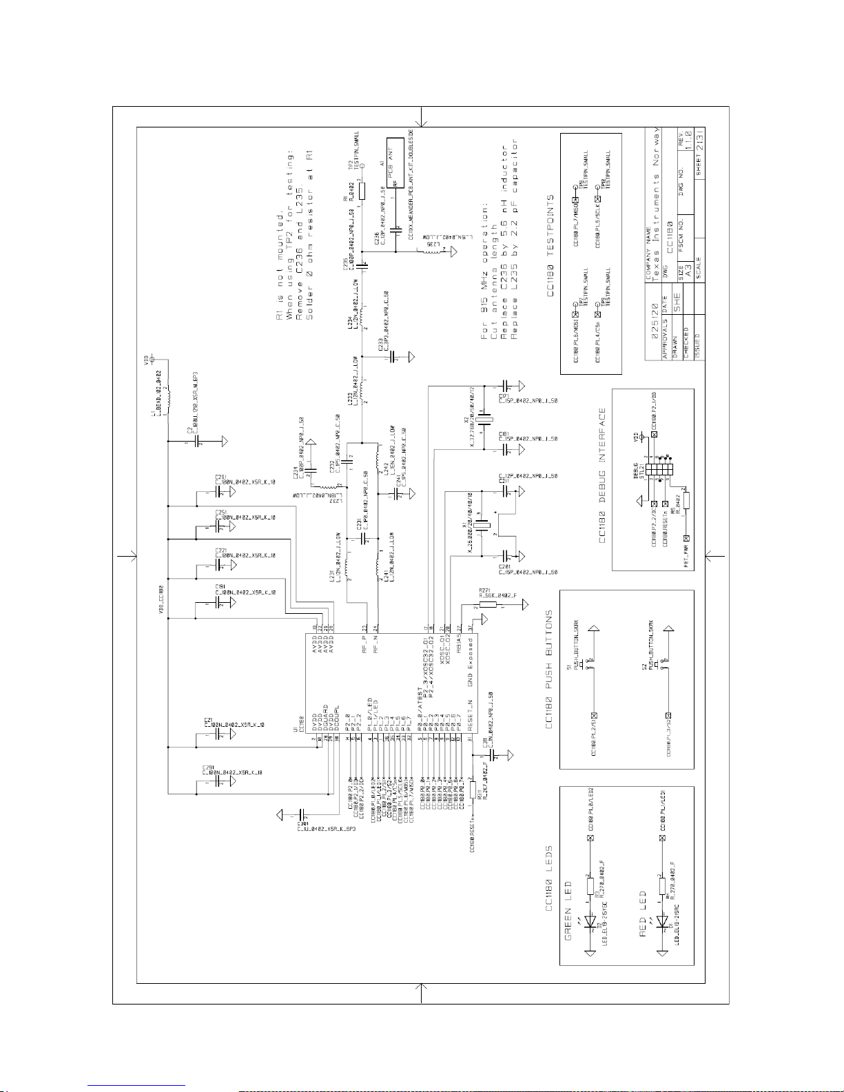
CC-6LOWPAN-DK-868
Page 43 of 61
Page 44

CC-6LOWPAN-DK-868
Page 44 of 61
Page 45

CC-6LOWPAN-DK-868
Page 45 of 61
Figure 28. CC1180DB, PCB Components Top Layer
Page 46

CC-6LOWPAN-DK-868
Page 46 of 61
Figure 29. CC1180DB, PCB Components Bottom Layer
Page 47

CC-6LOWPAN-DK-868
Page 47 of 61
Figure 30. CC1180DB, Layout Top Layer
Page 48
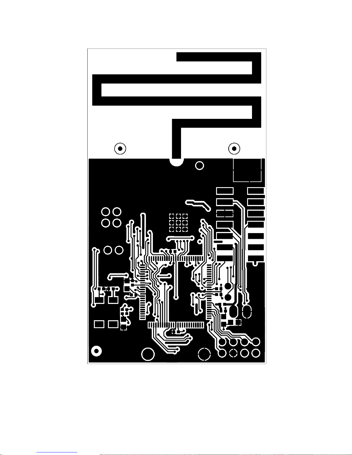
CC-6LOWPAN-DK-868
Page 48 of 61
Figure 31. CC1180DB, Layout Bottom Layer
Page 49

CC-6LOWPAN-DK-868
Page 49 of 61
Ref.
Part Name
Pcs/u
nit
Description
Manuf.
Part Number
B1
2XAAA
1
2xAAA battery holder,
2CELL AAA PC MNT
Keystone
2468
U1
CC1180
1
6LoWPAN Network
Processor
TI
CC1180
C5;C13;C15;C21;C30
;C34;C191;C221;C25
1;C261;C291
C_100N_0402_X
5R_K_10
11
Capacitor, 100n, 0402,
X5R, 10%, 10V
Murata
GRM155R71A104KA01D
C234-235
C_100P_0402_N
P0_J_50
2
Capacitor, 100p, 0402,
NP0, 5% 50V
Murata
GRM1555C1H101JZ01D
C2
C_100U_1210_X
5R_M_6P3
1
Capacitor, 100u, 1210,
X5R, 20%, 6.3V
Murata
GRM32EE70G107ME19L
C211;C236
C_12P_0402_NP
0_J_50
2
Capacitor, 12p, 0402, NP0,
5%, 50V
Murata
GRM1555C1H120JZ01D
C3132;C171;C181;C201
C_15P_0402_NP
0_J_50
5
Capacitor, 15p, 0402, NP0,
5%, 50V
Murata
GRM1555C1H150JZ01D
C311
C_1N_0402_NP0
_J_50
1
Capacitor, 1n, 0402, NP0,
5%, 50V
Murata
GRM1555C1H102JA01D
C231
C_1P0_0402_NP
0_C_50
1
Capacitor, 1p, 0402, NP0,
+/-0.25pF 50V
Murata
GRM1555C1H1R0CZ01D
C232;C241
C_1P5_0402_NP
0_C_50
2
Capacitor, 1p5, 0402, NP0,
+-0.25pF, 50V
Murata
GRM1555C1H1R5CZ01D
C301
C_1U_0402_X5R
_K_6P3
1
Capacitor, 1u, 0402, X5R,
10%, 6.3V
Murata
GRM155R60J105KE19D
C4
C_2N2_0603_X7
R_K_50
1
Capacitor, 2n2, 0603, X7R,
10%, 50V
Murata
GRM188R71H222KA01D
C233
C_3P3_0402_NP
0_C_50
1
Capacitor, 3p3, 0402, NP0,
+-0.25pF, 50V
Murata
GRM1555C1H3R3CZ01D
C33
C_470N_0402_X
5R_K_6P3
1
Capacitor, 470n, 0402,
X5R, 10%, 6.3V
Murata
GRM155R60J474KE19D
C7;C12
C_4U7_0603_X5
R_K_6
2
Capacitor, 4u7, 0603, X5R,
10%, 6.3V
Murata
GRM188R60J475KE19D
D1;D3
LED_EL1921SRC
2
LED, red, 0603, 1.7V,
19mcd
Everlight
19-21SDRC/S530-A3/TR8
D2;D4
LED_EL1921SYGC
2
LED, green, 0603, 2.0V,
16mcd
Everlight
19-21SYGC/S530-E1/TR8
L231;L233-234;L241
L_12N_0402_J_L
QW
4
Inductor, 12n, 0402, ±5%,
wire-wound type
Murata
LQW15AN12NJ00D
L235
L_15N_0402_J_L
QW
1
Inductor, 15n, 0402, ±5%,
wire-wound type
Murata
LQW15AN15NJ00D
L232;L242
L_18N_0402_J_L
QW
2
Inductor, 18n, 0402, ±5%,
wire-wound type
Murata
LQW15AN18NJ00D
L1-2
L_BEAD_102_04
02
2
EMI filter bead, 0402
1Kohms Tape GHz Band
Gen Use
Murata
BLM15HG102SN1D
U4
MSP430F5438AI
PZ
1
100 pins microcontroller
TI
MSP430F5438AIPZ
P1
PINROW_SMD_2
X2_2.54MM
1
2x2 pinrow, 2.54mm pitch,
SMD type
GradConn
BB02-HP041-KB3060B00
P2
PINROW_SMD_2
X7_2.54MM_DEB
UG
1
JTAG SMD Connector
GradConn
BB02-HR141-K08-00000
S1-5
PUSH_BUTTON_
SKRK
5
Momentary push-button,
SMD 3.9*2.9*2 mm
Alps
SKRKAEE010
R1;R5
R_0402
2
Resistor, general, 0402; Do
not mount
R13
R_0_0603
1
Resistor, 0 ohm, 0603, ±1%
Koa
RK73Z1JTTD
R12
R_10_0402_J
1
Resistor, 10 ohms, 0402,
5%
Koa
RK73H1ETTP10R0F
(±1%)
R3-4;R10-11
R_270_0402_F
4
Resistor, 270 ohms, 0402,
±1%
Koa
RK73H1E270RF-MR or
RK73H1ETTP2700F
R311
R_2K7_0402_F
1
Resistor, 2k7 ohms, 0402,
±1%
Koa
RK73H1ETTP2701F
R14
R_47K_0402_F
1
Resistor, 47k ohms, 0402,
±1%
Koa
RK73H1ETTP4702F
R271
R_56K_0402_F
1
Resistor, 56k ohms, 0402,
±1%
Koa
RK73H1ETTP5602F
DEBUG
STL21
1
10 pins connector
MPE-Garry
GmbH
STL21-A01XX-010-TRU
X1
X_26.000/20/40/4
0/10
1
Crystal, 26.000000MHz,
10.0pF, 50 ohms max,
20/40 ppm, -40C to +85C
NDK
NX3225GA, EXS00ACG01972
Page 50

CC-6LOWPAN-DK-868
Page 50 of 61
4.3 Edge Router, OMAP-L138 Experimenters Board
The Edge Router is based on the OMAP-L138 Experimenter‟s kit from TI. Full documentation,
schematics and layout for the OMAP-L138 Experimenter‟s board can be found here:
http://focus.ti.com/docs/toolsw/folders/print/tmdsexpl138.html. Please note that the OMAP board in
the CC-6LOWPAN-DK-868 does not include the LCD display.
It is very important that the switch S7-2 is in position ON, all other switches on S2 and S7 shall be in
position OFF.
Figure 32. OMAP-L138 Experimenter's Board Overview
1 – RS-232 Connection for Linux Console port.
2 – Connector J30, connection for CC1180EM using the Adapter Board.
3 – Switch S7. Position 2 need to be in ON position.
4 – Power switch
5 – Power connector
6 – Ethernet Connector
X2-3
X_32.768/20/50/4
0/12
2
Crystal, 32.768 kHz,
12.5pF, 20/50 ppm,SMD
package
Epson
Toyocom
MC-306
Total number of
components
69
Table 12. CC1180DB, Bill of Material
2
3
4
1
6
5
Page 51

CC-6LOWPAN-DK-868
Page 51 of 61
4.3.1 Adapter Board
The adapter board is used to enable connection of CC1180EM to the OMAP-L138 Experimenter‟s
Board, providing the RF interface for the Edge Router. The adapter board contains two LEDs with
function as described in the table below.
Green LED remains active Red LED
toggling
Both LEDs remains active
RF interface created, red LED blinks
when there is RF activity.
The CC1180 is in bootloader mode, accepting NanoBoot API
commands.
Table 13. Adapter Board LED functionality
4.3.1.1 Schematics, BOM and Layout
Page 52

CC-6LOWPAN-DK-868
Page 52 of 61
Page 53

CC-6LOWPAN-DK-868
Page 53 of 61
Figure 33. Adapter Board, PCB Components Top Layer
Figure 34. Adapter Board, PCB Components Bottom Layer
Page 54

CC-6LOWPAN-DK-868
Page 54 of 61
Figure 35. Adapter Board, Layout Top layer
Figure 36. Adapter Board, Layout Bottom Layer
Page 55

CC-6LOWPAN-DK-868
Page 55 of 61
Part Type
Designator
Footprint
Description
Part Number
Manuf.
0.1uF
C1
CAP_0603
CAPACITOR
ECJ1VB1C104K
Panasonic
0.1uF
C2
CAP_0603
CAPACITOR
ECJ1VB1C104K
Panasonic
2.2uF
C3
CAP_0603
CAPACITOR
GRM188R61C225KE
15D
Murata
EM HEADER
JP1
HEADER
10X2(SAMTFM)(SMT)
CONNECTOR
TFM-110-02-SM-D-AK-TR
Samtec
EM HEADER
JP2
HEADER
10X2(SAMTFM)(SMT)
CONNECTOR
TFM-110-02-SM-D-AK-TR
Samtec
HEADER(DF40C100DP)
JP30
HEADER(DF40C100DP)
CONNECTOR
DF40C-100DP-
0.4V(51)
Hirose
GREEN LED
D1
LED(SMT0603)
DIODE
19-21SYGC
Everlight
RED LED
D2
LED(SMT0603)
DIODE
19-21SURC
Everlight
TPS79333
U1
SOT23(5)(DBV)
IC
TPS79333DBV
Texas
Instruments
221 Ohm
R1
RES_0603
RESISTOR
ERJ3EKF2210V
Panasonic
221 Ohm
R2
RES_0603
RESISTOR
ERJ3EKF2210V
Panasonic
Table 14. Adapter Board, Bill of Material
4.3.2 CC1180EM
The CC1180EM is the RF interface for the OMAP-L138 (acting as Edge Router).
4.3.2.1 Schematics, BOM and Layout
Page 56

CC-6LOWPAN-DK-868
Page 56 of 61
Page 57

CC-6LOWPAN-DK-868
Page 57 of 61
Figure 37. CC1180EM, PCB Components Top Layer
Figure 38. CC1180EM, PCB Components Bottom Layer
Page 58
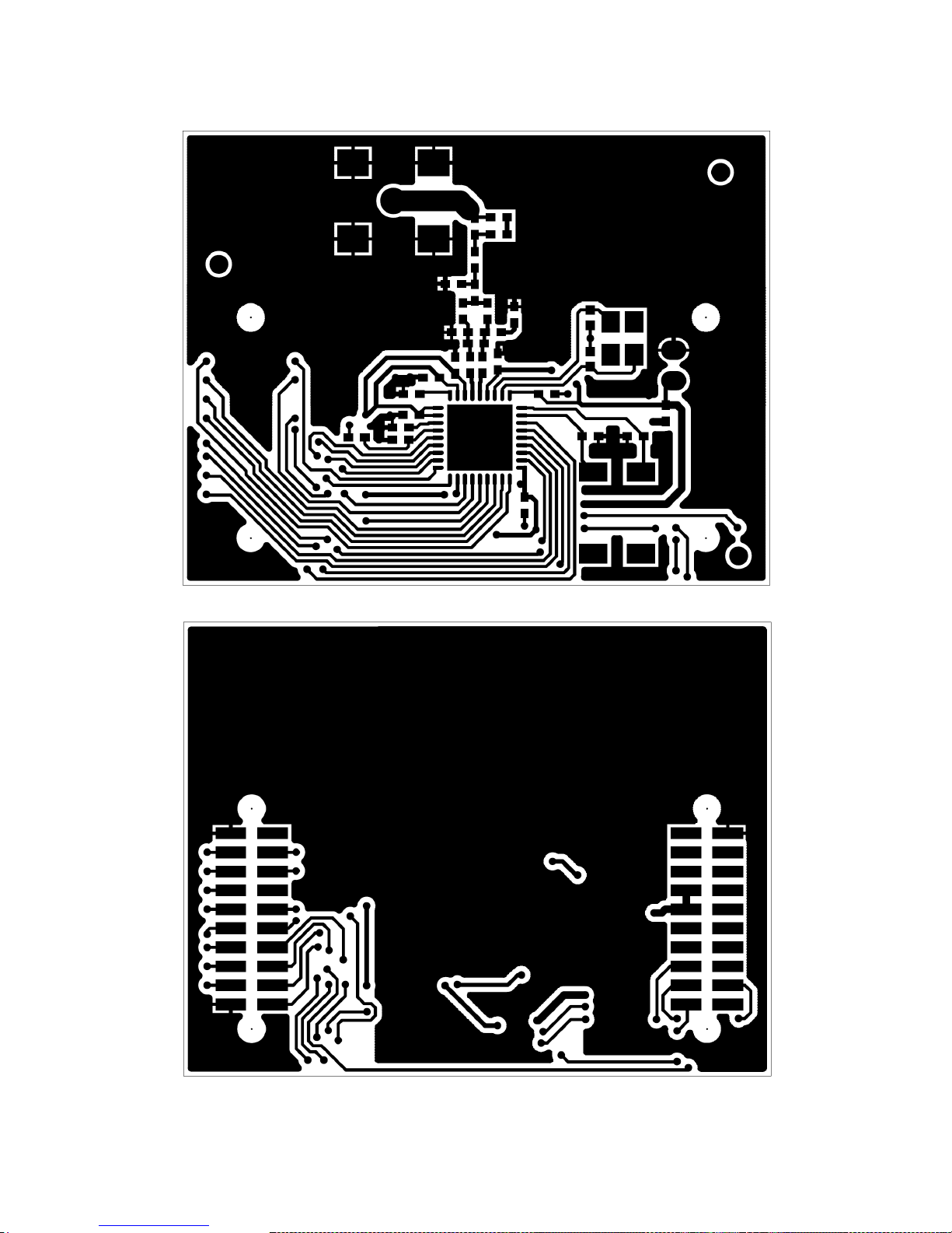
CC-6LOWPAN-DK-868
Page 58 of 61
Figure 39. CC1180EM, Layout Top Layer
Figure 40. CC1180EM, Layout Bottom Layer
Page 59

CC-6LOWPAN-DK-868
Page 59 of 61
Ref.
Part Name
Pcs/unit
Description
Manuf.
Part Number
U1
CC1180
1
6LoWPAN Network
Processor
TI
CC1180
C236
C_0402
1
Capacitor, general,
0402; Do not mount
C21;C291
C_100N_0402_X5R_K_1
0
2
Capacitor, 100n,
0402, X5R, 10%,
10V
Murata
GRM155R71A104KA01D
C234-235
C_100P_0402_NP0_J_50
2
Capacitor, 100p,
0402, NP0, 5% 50V
Murata
GRM1555C1H101JZ01D
C191;C251
C_10N_0402_X7R_K_25
2
Capacitor, 10n,
0402, X7R, 10%,
25V
Murata
GRM155R71E103KA01D
C211
C_12P_0402_NP0_J_50
1
Capacitor, 12p,
0402, NP0, 5%, 50V
Murata
GRM1555C1H120JZ01D
C171;C181;C201
C_15P_0402_NP0_J_50
3
Capacitor, 15p,
0402, NP0, 5%, 50V
Murata
GRM1555C1H150JZ01D
C311
C_1N_0402_NP0_J_50
1
Capacitor, 1n, 0402,
NP0, 5%, 50V
Murata
GRM1555C1H102JA01D
C231
C_1P0_0402_NP0_C_50
1
Capacitor, 1p, 0402,
NP0, +/-0.25pF 50V
Murata
GRM1555C1H1R0CZ01D
C232;C241
C_1P5_0402_NP0_C_50
2
Capacitor, 1p5,
0402, NP0, +-
0.25pF, 50V
Murata
GRM1555C1H1R5CZ01D
C301
C_1U_0402_X5R_K_6P3
1
Capacitor, 1u, 0402,
X5R, 10%, 6.3V
Murata
GRM155R60J105KE19D
C261
C_220P_0402_NP0_J_50
1
Capacitor, 220p,
0402, NP0, 5%, 50V
Murata
GRM1555C1H221JA01D
C221
C_2P2_0402_NP0_C_50
1
Capacitor, 2p2,
0402, NP0, +-
0.25pF, 50V
Murata
GRM1555C1H2R2CZ01
C1
C_2U2_0805_X5R_K_10
1
Capacitor, 2u2,
0805, X5R, 10%,
10V
Murata
GRM219R61A225KA01D
C233
C_3P3_0402_NP0_C_50
1
Capacitor, 3p3,
0402, NP0, +-
0.25pF, 50V
Murata
GRM1555C1H3R3CZ01D
L235
L_0402
1
Inductor, general,
0402; Do not mount
L231;L233234;L241
L_12N_0402_J
4
Inductor, 12n, 0402,
±5%
Murata
LQG15HS12NJ02D
L232;L242
L_18N_0402_J
2
Inductor, 18n, 0402,
±5%
Murata
LQG15HS18NJ02D
L1
L_BEAD_102_0402
1
EMI filter bead, 0402
1Kohms Tape GHz
Band Gen Use
Murata
BLM15HG102SN1D
R311
R_2K7_0402_F
1
Resistor, 2k7 ohms,
0402, ±1%
Koa
RK73H1ETTP2701F
R271
R_56K_0402_F
1
Resistor, 56k ohms,
0402, ±1%
Koa
RK73H1ETTP5602F
P3
SMA_SMD
1
SMA connector,
straight SMD-mount
HusTsan
Group
Taiwan
SMA-10V21-TGG
P1-2
SMD_SOCKET_2X10
2
SMD pinrow socket,
.050 spacing, 2x10
Samtec
SFM-110-02-SM-D-A-KTR
X1
X_26.000/20/40/40/10
1
Crystal,
26.000000MHz,
10.0pF, 50 ohms
max, 20/40 ppm, 40C to +85C
NDK
NX3225GA, EXS00ACG01972
X2
X_32.768/20/50/40/12
1
Crystal, 32.768 kHz,
12.5pF, 20/50
ppm,SMD package
Epson
Toyocom
MC-306
Total number of
components
36
Table 15. CC1180EM, Bill of Material
Page 60

CC-6LOWPAN-DK-868
Page 60 of 61
5 FAQ
5.1 Send UDP packets from PC
One easy way to communicate with the nodes in the 6LoWPAN network using UDP from a PC is via
the Netcat program. Netcat is a tool that are included in almost every Linux distribution, to check if
you have netcat installed run the nc command in Linux. For W indows users‟ netcat6 can be
downloaded from here.
Netcat can be used to send raw ASCII UDP packets to the nodes. This is how to open a UDP
connection on port 61641 to the IPv6 address 2001:0:0:0:0:ff:fe00:7854 using nc6 for
Windows. Destination port is 61641.
nc6 -u -p 61641 2001:0:0:0:0:ff:fe00:7854 61641<enter>
After opening a connection to the IPv6 address you can send any ASCII data followed by <enter>.
nc6 will add a new line at the end of the data and the data (ASCII string) will be send to the specific
IPv6 address.
To close the connection press <ctrl-c>.
For more details on nc6 run the command nc6 -help, if you're using nc in Linux the command would
be nc -help.
NOTE: If using the nc tool on Linux, one has to specify that the tool shall use IPv6 by the -6 syntax:
nc -6 -u -p 61641 2001:0:0:0:0:ff:fe00:7854 61641<enter>
This tool enables simple communication with nodes (or any IPv6 address) without the need of a
special program.
5.2 Too Much Code
The free version (kick start) of IAR for MSP430 is limited to 8kB of code. If you get this error:
"Fatal Error[e89]: Too much object code produced (more than 0x2000 bytes) for this package "
This means that you have exceeded the 8kB limit. The size of the CODE + CONST must be less than
8kB. You can check the size by looking at the bottom of the Linker Listing (HTML file generated by the
compiler, located in the Output directory). You can either trim down your application, port your
application to Code Composer (which has a 16kB limit for the free version), buy a full license of IAR,
or try the 30 day evaluation edition of IAR. If changing IAR version, remember to clean your project
before rebuilding.
5.3 Linux kernel and File System
The current Linux kernel and File System that is used on the OMAP-L138 board in the kit can be
obtained from TI. Please contact your local support.
Page 61

CC-6LOWPAN-DK-868
Page 61 of 61
6 References
[1] Draft-ietf-6lowpan-hc-13 (draft-ietf-6lowpan-hc-13)
[2] Draft-ietf-6lowpan-nd-13 (draft-ietf-6lowpan-nd-13)
[3] Draft-ietf-roll-rpl-13 (draft-ietf-roll-rpl-13)
[4] IEEE 802.15.4g specification
[5] IEEE 802.15.4e specification
[6] Sensinode NanoRouter2.0.pdf
[7] Sensinode NanoStack2.0lite-v1.0-01.pdf
[8] Sensinode NanoSocket API 1.0.pdf
[9] Sensinode NAPProtocol1.0.pdf
[10] Sensinode NodeView2.0.pdf
[11] Sensinode NanoHost Example 1.0-01.pdf
[12] Sensinode NAPSocketLibrary1.0-01.pdf
[13] Sensinode RFConfigurationAppNote1.0.pdf
[14] CC-6LOWPAN-DK-868 Quick Start Guide (SWRU276.pdf)
[15] CC1180 Datasheet (SWRS113.pdf)
7 Development Kit Ordering Information
Orderable Evaluation Module
Description
Minimum Order Quantity
CC-6LOWPAN-DK-868
6LoWPAN Development Kit, 868/915 MHz
1
Table 16. Development Kit Ordering Information
8 General Information
8.1 Document History
Revision
Date
Description/Changes
SWRU298
12.09.2011
First User‟s Guide release.
Table 17. Document History
Page 62

EVALUATION BOARD/KIT/MODULE (EVM) ADDITIONAL TERMS
Texas Instruments (TI) provides the enclosed Evaluation Board/Kit/Module (EVM) under the following conditions:
The user assumes all responsibility and liability for proper and safe handling of the goods. Further, the user indemnifies TI from all claims
arising from the handling or use of the goods.
Should this evaluation board/kit not meet the specifications indicated in the User’s Guide, the board/kit may be returned within 30 days from
the date of delivery for a full refund. THE FOREGOING LIMITED WARRANTY IS THE EXCLUSIVE WARRANTY MADE BY SELLER TO
BUYER AND IS IN LIEU OF ALL OTHER WARRANTIES, EXPRESSED, IMPLIED, OR STATUTORY, INCLUDING ANY WARRANTY OF
MERCHANTABILITY OR FITNESS FOR ANY PARTICULAR PURPOSE. EXCEPT TO THE EXTENT OF THE INDEMNITY SET FORTH
ABOVE, NEITHER PARTY SHALL BE LIABLE TO THE OTHER FOR ANY INDIRECT, SPECIAL, INCIDENTAL, OR CONSEQUENTIAL
DAMAGES.
Please read the User's Guide and, specifically, the Warnings and Restrictions notice in the User's Guide prior to handling the product. This
notice contains important safety information about temperatures and voltages. For additional information on TI's environmental and/or safety
programs, please visit www.ti.com/esh or contact TI.
No license is granted under any patent right or other intellectual property right of TI covering or relating to any machine, process, or
combination in which such TI products or services might be or are used. TI currently deals with a variety of customers for products, and
therefore our arrangement with the user is not exclusive. TI assumes no liability for applications assistance, customer product design,
software performance, or infringement of patents or services described herein.
REGULATORY COMPLIANCE INFORMATION
As noted in the EVM User’s Guide and/or EVM itself, this EVM and/or accompanying hardware may or may not be subject to the Federal
Communications Commission (FCC) and Industry Canada (IC) rules.
For EVMs not subject to the above rules, this evaluation board/kit/module is intended for use for ENGINEERING DEVELOPMENT,
DEMONSTRATION OR EVALUATION PURPOSES ONLY and is not considered by TI to be a finished end product fit for general consumer
use. It generates, uses, and can radiate radio frequency energy and has not been tested for compliance with the limits of computing
devices pursuant to part 15 of FCC or ICES-003 rules, which are designed to provide reasonable protection against radio frequency
interference. Operation of the equipment may cause interference with radio communications, in which case the user at his own expense will
be required to take whatever measures may be required to correct this interference.
General Statement for EVMs including a radio
User Power/Frequency Use Obligations: This radio is intended for development/professional use only in legally allocated frequency and
power limits. Any use of radio frequencies and/or power availability of this EVM and its development application(s) must comply with local
laws governing radio spectrum allocation and power limits for this evaluation module. It is the user’s sole responsibility to only operate this
radio in legally acceptable frequency space and within legally mandated power limitations. Any exceptions to this are strictly prohibited and
unauthorized by Texas Instruments unless user has obtained appropriate experimental/development licenses from local regulatory
authorities, which is responsibility of user including its acceptable authorization.
For EVMs annotated as FCC – FEDERAL COMMUNICATIONS COMMISSION Part 15 Compliant
Caution
This device complies with part 15 of the FCC Rules. Operation is subject to the following two conditions: (1) This device may not cause
harmful interference, and (2) this device must accept any interference received, including interference that may cause undesired operation.
Changes or modifications not expressly approved by the party responsible for compliance could void the user's authority to operate the
equipment.
FCC Interference Statement for Class A EVM devices
This equipment has been tested and found to comply with the limits for a Class A digital device, pursuant to part 15 of the FCC Rules.
These limits are designed to provide reasonable protection against harmful interference when the equipment is operated in a commercial
environment. This equipment generates, uses, and can radiate radio frequency energy and, if not installed and used in accordance with the
instruction manual, may cause harmful interference to radio communications. Operation of this equipment in a residential area is likely to
cause harmful interference in which case the user will be required to correct the interference at his own expense.
Page 63

FCC Interference Statement for Class B EVM devices
This equipment has been tested and found to comply with the limits for a Class B digital device, pursuant to part 15 of the FCC Rules.
These limits are designed to provide reasonable protection against harmful interference in a residential installation. This equipment
generates, uses and can radiate radio frequency energy and, if not installed and used in accordance with the instructions, may cause
harmful interference to radio communications. However, there is no guarantee that interference will not occur in a particular installation. If
this equipment does cause harmful interference to radio or television reception, which can be determined by turning the equipment off and
on, the user is encouraged to try to correct the interference by one or more of the following measures:
• Reorient or relocate the receiving antenna.
• Increase the separation between the equipment and receiver.
• Connect the equipment into an outlet on a circuit different from that to which the receiver is connected.
• Consult the dealer or an experienced radio/TV technician for help.
For EVMs annotated as IC – INDUSTRY CANADA Compliant
This Class A or B digital apparatus complies with Canadian ICES-003.
Changes or modifications not expressly approved by the party responsible for compliance could void the user’s authority to operate the
equipment.
Concerning EVMs including radio transmitters
This device complies with Industry Canada licence-exempt RSS standard(s). Operation is subject to the following two conditions: (1) this
device may not cause interference, and (2) this device must accept any interference, including interference that may cause undesired
operation of the device.
Concerning EVMs including detachable antennas
Under Industry Canada regulations, this radio transmitter may only operate using an antenna of a type and maximum (or lesser) gain
approved for the transmitter by Industry Canada. To reduce potential radio interference to other users, the antenna type and its gain should
be so chosen that the equivalent isotropically radiated power (e.i.r.p.) is not more than that necessary for successful communication.
This radio transmitter has been approved by Industry Canada to operate with the antenna types listed in the user guide with the maximum
permissible gain and required antenna impedance for each antenna type indicated. Antenna types not included in this list, having a gain
greater than the maximum gain indicated for that type, are strictly prohibited for use with this device.
Cet appareil numérique de la classe A ou B est conforme à la norme NMB-003 du Canada.
Les changements ou les modifications pas expressément approuvés par la partie responsable de la conformité ont pu vider l’autorité de
l'utilisateur pour actionner l'équipement.
Concernant les EVMs avec appareils radio
Le présent appareil est conforme aux CNR d'Industrie Canada applicables aux appareils radio exempts de licence. L'exploitation est
autorisée aux deux conditions suivantes : (1) l'appareil ne doit pas produire de brouillage, et (2) l'utilisateur de l'appareil doit accepter tout
brouillage radioélectrique subi, même si le brouillage est susceptible d'en compromettre le fonctionnement.
Concernant les EVMs avec antennes détachables
Conformément à la réglementation d'Industrie Canada, le présent émetteur radio peut fonctionner avec une antenne d'un type et d'un gain
maximal (ou inférieur) approuvé pour l'émetteur par Industrie Canada. Dans le but de réduire les risques de brouillage radioélectrique à
l'intention des autres utilisateurs, il faut choisir le type d'antenne et son gain de sorte que la puissance isotrope rayonnée équivalente
(p.i.r.e.) ne dépasse pas l'intensité nécessaire à l'établissement d'une communication satisfaisante.
Le présent émetteur radio a été approuvé par Industrie Canada pour fonctionner avec les types d'antenne énumérés dans le manuel
d’usage et ayant un gain admissible maximal et l'impédance requise pour chaque type d'antenne. Les types d'antenne non inclus dans
cette liste, ou dont le gain est supérieur au gain maximal indiqué, sont strictement interdits pour l'exploitation de l'émetteur.
SPACER
SPACER
SPACER
SPACER
SPACER
SPACER
SPACER
SPACER
Page 64

【【Important Notice for Users of this Product in Japan】】
This development kit is NOT certified as Confirming to Technical Regulations of Radio Law of Japan
If you use this product in Japan, you are required by Radio Law of Japan to follow the instructions below with respect to this product:
1. Use this product in a shielded room or any other test facility as defined in the notification #173 issued by Ministry of Internal Affairs and
Communications on March 28, 2006, based on Sub-section 1.1 of Article 6 of the Ministry’s Rule for Enforcement of Radio Law of
Japan,
2. Use this product only after you obtained the license of Test Radio Station as provided in Radio Law of Japan with respect to this
product, or
3. Use of this product only after you obtained the Technical Regulations Conformity Certification as provided in Radio Law of Japan with
respect to this product. Also, please do not transfer this product, unless you give the same notice above to the transferee. Please note
that if you could not follow the instructions above, you will be subject to penalties of Radio Law of Japan.
(address) 24-1, Nishi-Shinjuku 6 chome, Shinjuku-ku, Tokyo, Japan
http://www.tij.co.jp
【ご使用にあたっての注】
本開発キットは技術基準適合証明を受けておりません。
本製品のご使用に際しては、電波法遵守のため、以下のいずれかの措置を取っていただく必要がありますのでご注意ください。
1. 電波法施行規則第6条第1項第1号に基づく平成18年3月28日総務省告示第173号で定められた電波暗室等の試験設備でご使用いただく。
2. 実験局の免許を取得後ご使用いただく。
3. 技術基準適合証明を取得後ご使用いただく。
なお、本製品は、上記の「ご使用にあたっての注意」を譲渡先、移転先に通知しない限り、譲渡、移転できないものとします。
上記を遵守頂けない場合は、電波法の罰則が適用される可能性があることをご留意ください。
日本テキサス・インスツルメンツ株式会社
東京都新宿区西新宿6丁目24番1号
西新宿三井ビル
http://www.tij.co.jp
Texas Instruments Japan Limited
SPACER
SPACER
SPACER
SPACER
SPACER
SPACER
SPACER
SPACER
SPACER
SPACER
SPACER
SPACER
SPACER
SPACER
SPACER
SPACER
Page 65

EVALUATION BOARD/KIT/MODULE (EVM)
WARNINGS, RESTRICTIONS AND DISCLAIMERS
For Feasibility Evaluation Only, in Laboratory/Development Environments. Unless otherwise indicated, this EVM is not a finished
electrical equipment and not intended for consumer use. It is intended solely for use for preliminary feasibility evaluation in
laboratory/development environments by technically qualified electronics experts who are familiar with the dangers and application risks
associated with handling electrical mechanical components, systems and subsystems. It should not be used as all or part of a finished end
product.
Your Sole Responsibility and Risk. You acknowledge, represent and agree that:
1. You have unique knowledge concerning Federal, State and local regulatory requirements (including but not limited to Food and Drug
Administration regulations, if applicable) which relate to your products and which relate to your use (and/or that of your employees,
affiliates, contractors or designees) of the EVM for evaluation, testing and other purposes.
2. You have full and exclusive responsibility to assure the safety and compliance of your products with all such laws and other applicable
regulatory requirements, and also to assure the safety of any activities to be conducted by you and/or your employees, affiliates,
contractors or designees, using the EVM. Further, you are responsible to assure that any interfaces (electronic and/or mechanical)
between the EVM and any human body are designed with suitable isolation and means to safely limit accessible leakage currents to
minimize the risk of electrical shock hazard.
3. You will employ reasonable safeguards to ensure that your use of the EVM will not result in any property damage, injury or death, even
if the EVM should fail to perform as described or expected.
4. You will take care of proper disposal and recycling of the EVM’s electronic components and packing materials.
Certain Instructions. It is important to operate this EVM within TI’s recommended specifications and environmental considerations per the
user guidelines. Exceeding the specified EVM ratings (including but not limited to input and output voltage, current, power, and
environmental ranges) may cause property damage, personal injury or death. If there are questions concerning these ratings please contact
a TI field representative prior to connecting interface electronics including input power and intended loads. Any loads applied outside of the
specified output range may result in unintended and/or inaccurate operation and/or possible permanent damage to the EVM and/or
interface electronics. Please consult the EVM User's Guide prior to connecting any load to the EVM output. If there is uncertainty as to the
load specification, please contact a TI field representative. During normal operation, some circuit components may have case temperatures
greater than 60°C as long as the input and output are maintained at a normal ambient operating temperature. These components include
but are not limited to linear regulators, switching transistors, pass transistors, and current sense resistors which can be identified using the
EVM schematic located in the EVM User's Guide. When placing measurement probes near these devices during normal operation, please
be aware that these devices may be very warm to the touch. As with all electronic evaluation tools, only qualified personnel knowledgeable
in electronic measurement and diagnostics normally found in development environments should use these EVMs.
Agreement to Defend, Indemnify and Hold Harmless. You agree to defend, indemnify and hold TI, its licensors and their representatives
harmless from and against any and all claims, damages, losses, expenses, costs and liabilities (collectively, "Claims") arising out of or in
connection with any use of the EVM that is not in accordance with the terms of the agreement. This obligation shall apply whether Claims
arise under law of tort or contract or any other legal theory, and even if the EVM fails to perform as described or expected.
Safety-Critical or Life-Critical Applications. If you intend to evaluate the components for possible use in safety critical applications (such
as life support) where a failure of the TI product would reasonably be expected to cause severe personal injury or death, such as devices
which are classified as FDA Class III or similar classification, then you must specifically notify TI of such intent and enter into a separate
Assurance and Indemnity Agreement.
Mailing Address: Texas Instruments, Post Office Box 655303, Dallas, Texas 75265
Copyright © 2012, Texas Instruments Incorporated
Page 66

IMPORTANT NOTICE
Texas Instruments Incorporated and its subsidiaries (TI) reserve the right to make corrections, enhancements, improvements and other
changes to its semiconductor products and services per JESD46, latest issue, and to discontinue any product or service per JESD48, latest
issue. Buyers should obtain the latest relevant information before placing orders and should verify that such information is current and
complete. All semiconductor products (also referred to herein as “components”) are sold subject to TI’s terms and conditions of sale
supplied at the time of order acknowledgment.
TI warrants performance of its components to the specifications applicable at the time of sale, in accordance with the warranty in TI’s terms
and conditions of sale of semiconductor products. Testing and other quality control techniques are used to the extent TI deems necessary
to support this warranty. Except where mandated by applicable law, testing of all parameters of each component is not necessarily
performed.
TI assumes no liability for applications assistance or the design of Buyers’ products. Buyers are responsible for their products and
applications using TI components. To minimize the risks associated with Buyers’ products and applications, Buyers should provide
adequate design and operating safeguards.
TI does not warrant or represent that any license, either express or implied, is granted under any patent right, copyright, mask work right, or
other intellectual property right relating to any combination, machine, or process in which TI components or services are used. Information
published by TI regarding third-party products or services does not constitute a license to use such products or services or a warranty or
endorsement thereof. Use of such information may require a license from a third party under the patents or other intellectual property of the
third party, or a license from TI under the patents or other intellectual property of TI.
Reproduction of significant portions of TI information in TI data books or data sheets is permissible only if reproduction is without alteration
and is accompanied by all associated warranties, conditions, limitations, and notices. TI is not responsible or liable for such altered
documentation. Information of third parties may be subject to additional restrictions.
Resale of TI components or services with statements different from or beyond the parameters stated by TI for that component or service
voids all express and any implied warranties for the associated TI component or service and is an unfair and deceptive business practice.
TI is not responsible or liable for any such statements.
Buyer acknowledges and agrees that it is solely responsible for compliance with all legal, regulatory and safety-related requirements
concerning its products, and any use of TI components in its applications, notwithstanding any applications-related information or support
that may be provided by TI. Buyer represents and agrees that it has all the necessary expertise to create and implement safeguards which
anticipate dangerous consequences of failures, monitor failures and their consequences, lessen the likelihood of failures that might cause
harm and take appropriate remedial actions. Buyer will fully indemnify TI and its representatives against any damages arising out of the use
of any TI components in safety-critical applications.
In some cases, TI components may be promoted specifically to facilitate safety-related applications. With such components, TI’s goal is to
help enable customers to design and create their own end-product solutions that meet applicable functional safety standards and
requirements. Nonetheless, such components are subject to these terms.
No TI components are authorized for use in FDA Class III (or similar life-critical medical equipment) unless authorized officers of the parties
have executed a special agreement specifically governing such use.
Only those TI components which TI has specifically designated as military grade or “enhanced plastic” are designed and intended for use in
military/aerospace applications or environments. Buyer acknowledges and agrees that any military or aerospace use of TI components
which have not been so designated is solely at the Buyer's risk, and that Buyer is solely responsible for compliance with all legal and
regulatory requirements in connection with such use.
TI has specifically designated certain components which meet ISO/TS16949 requirements, mainly for automotive use. Components which
have not been so designated are neither designed nor intended for automotive use; and TI will not be responsible for any failure of such
components to meet such requirements.
Products Applications
Audio www.ti.com/audio Automotive and Transportation www.ti.com/automotive
Amplifiers amplifier.ti.com Communications and Telecom www.ti.com/communications
Data Converters dataconverter.ti.com Computers and Peripherals www.ti.com/computers
DLP® Products www.dlp.com Consumer Electronics www.ti.com/consumer-apps
DSP dsp.ti.com Energy and Lighting www.ti.com/energy
Clocks and Timers www.ti.com/clocks Industrial www.ti.com/industrial
Interface interface.ti.com Medical www.ti.com/medical
Logic logic.ti.com Security www.ti.com/security
Power Mgmt power.ti.com Space, Avionics and Defense www.ti.com/space-avionics-defense
Microcontrollers microcontroller.ti.com Video and Imaging www.ti.com/video
RFID www.ti-rfid.com
OMAP Applications Processors www.ti.com/omap TI E2E Community e2e.ti.com
Wireless Connectivity www.ti.com/wirelessconnectivity
Mailing Address: Texas Instruments, Post Office Box 655303, Dallas, Texas 75265
Copyright © 2012, Texas Instruments Incorporated
 Loading...