

Page 1

CC3220 SimpleLink™ Wi-Fi®and Internet of
Things Solution, a Single-Chip Wireless MCU
Getting Started Guide
Literature Number: SWRU461B
February 2017–Revised June 2018
Page 2

Contents
Preface ........................................................................................................................................ 3
1 Download and Installation..................................................................................................... 4
1.1 CC3220 Software Development Kit (SDK) ............................................................................... 4
1.2 Service Pack ................................................................................................................. 4
1.3 UniFlash Tool................................................................................................................. 4
1.4 Serial Terminal ............................................................................................................... 6
1.5 Pin Mux Tool ................................................................................................................. 7
1.6 XDS110 Driver Installation.................................................................................................. 7
1.7 Debugger/IDE............................................................................................................... 10
1.7.1 CCS................................................................................................................. 10
1.7.2 IAR .................................................................................................................. 12
1.7.3 GCC................................................................................................................. 12
1.8 Operating Systems......................................................................................................... 12
1.8.1 TI-RTOS............................................................................................................ 12
1.8.2 FreeRTOS.......................................................................................................... 12
2 Execute your First Application............................................................................................. 13
2.1 CCS.......................................................................................................................... 14
2.1.1 Import and Configure Project.................................................................................... 14
2.1.2 Recompilation for Other Device Variants ...................................................................... 17
2.2 IAR ........................................................................................................................... 17
2.3 GCC.......................................................................................................................... 17
2.4 Download the Application ................................................................................................. 18
2.4.1 Image Creation for Secure Device (CC3220S and CC3220SF)............................................ 22
2.4.2 Image Creation for Nonsecure Device (CC3220)............................................................. 27
2.5 Launching the Application................................................................................................. 29
2.6 Using the Application ...................................................................................................... 30
3 Use the Debugger/IDE......................................................................................................... 34
3.1 Prerequisites................................................................................................................ 34
3.2 Development Formatting for SFLASH................................................................................... 34
3.3 CCS.......................................................................................................................... 35
3.3.1 Rebuild the SimpleLink™ Library for Debug Configuration.................................................. 35
3.3.2 Download and Debug the WLAN Station Example ........................................................... 36
3.4 IAR ........................................................................................................................... 39
3.5 GCC.......................................................................................................................... 39
Revision History.......................................................................................................................... 40
2
Contents
Copyright © 2017–2018, Texas Instruments Incorporated
SWRU461B–February 2017–Revised June 2018
Submit Documentation Feedback
Page 3

This guide is intended to assist users in the initial setup and demonstration of running their first sample
application for the CC3220, CC3220S, and CC3220SF SimpleLink™ Wi-Fi®and Internet of Things
Solution, a Single-Chip Wireless MCU from Texas Instruments™. The guide explains how to install the
software development kit (SDK) and various other tools required to get started with the first application.
Trademarks
SimpleLink, Texas Instruments, Code Composer Studio are trademarks of Texas Instruments.
Bluetooth is a registered trademark of Bluetooth SIG.
IAR Embedded Workbench is a registered trademark of IAR Systems AB.
Linux is a registered trademark of Linux Foundation.
Microsoft is a registered trademark of Microsoft Corporation.
Wi-Fi is a registered trademark of Wi-Fi alliance.
All other trademarks are the property of their respective owners.
Introduction
This preliminary release of the Getting Started guide is focused on the Code Composer Studio™ (CCS)
IDE.
For detailed IAR instructions, refer to:
<sdk-installation-path>\docs\cc3220\CC3220_SDK_IAR_project_setup_guide.html
GCC is currently not supported.
The CC3220 device is part of the SimpleLink microcontroller (MCU) platform, which consists of Wi-Fi,
Bluetooth®low energy, Sub-1 GHz, and host MCUs. All share a common, easy-to-use development
environment with a single core software development kit (SDK) and rich tool set. A one-time integration of
the SimpleLink platform lets you add any combination of devices from the portfolio into your design. The
ultimate goal of the SimpleLink platform is to achieve 100 percent code reuse when your design
requirements change. For more information, visit www.ti.com/simplelink.
Read This First
SWRU461B–February 2017–Revised June 2018
Preface
Prerequisites
The user is expected to have the following:
• CC3220S-LAUNCHXL or CC3220SF-LAUNCHXL
• An 802.11b/g/n (2.4-GHz) Wireless Access Point (AP)
• A computer running Microsoft®Windows 7
SWRU461B–February 2017–Revised June 2018
Submit Documentation Feedback
Copyright © 2017–2018, Texas Instruments Incorporated
Preface
3
Page 4
1.1 CC3220 Software Development Kit (SDK)
• Download the following software at CC3220 SDK package.
• Run the installer by double-clicking on the CC3220 SDK installer.
• Read and accept the license agreement to proceed.
• Choose the desired path to place the package (else default is chosen).
• Proceed with the installation and click Finish once done.
1.2 Service Pack
If the board is not already flashed with the service pack for SDK <version>, the latest service pack for
SDK <version> must be flashed on the CC3220 wireless MCU. The most updated service pack is
available under <sdk-installation>\tools\cc32xx_tools\servicepack-cc3x20. To program the service pack
with an UniFlash, the binary file (.bin) must be loaded to the Files/Service Pack.
1.3 UniFlash Tool
UniFlash is a stand-alone tool used to program on-chip flash memory on TI MCUs and onboard flash
memory for Sitara processors. The tool lets the developer download application image, service pack, and
other files on the serial flash of the CC3220 device. It also enables the creation of OTA (Over-The-Air)
images.
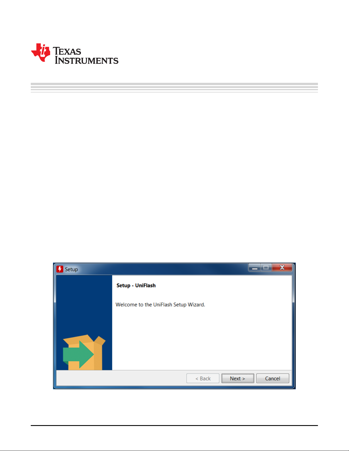
1. Download the Image Creator tool from http://www.ti.com/tool/uniflash.
2. Run the installer by double-clicking on it. Click Next to continue, as shown in Figure 1-1.
Chapter 1
SWRU461B–February 2017–Revised June 2018
Download and Installation
Figure 1-1. Install UniFlash
4
Download and Installation
Copyright © 2017–2018, Texas Instruments Incorporated
SWRU461B–February 2017–Revised June 2018
Submit Documentation Feedback
Page 5
www.ti.com
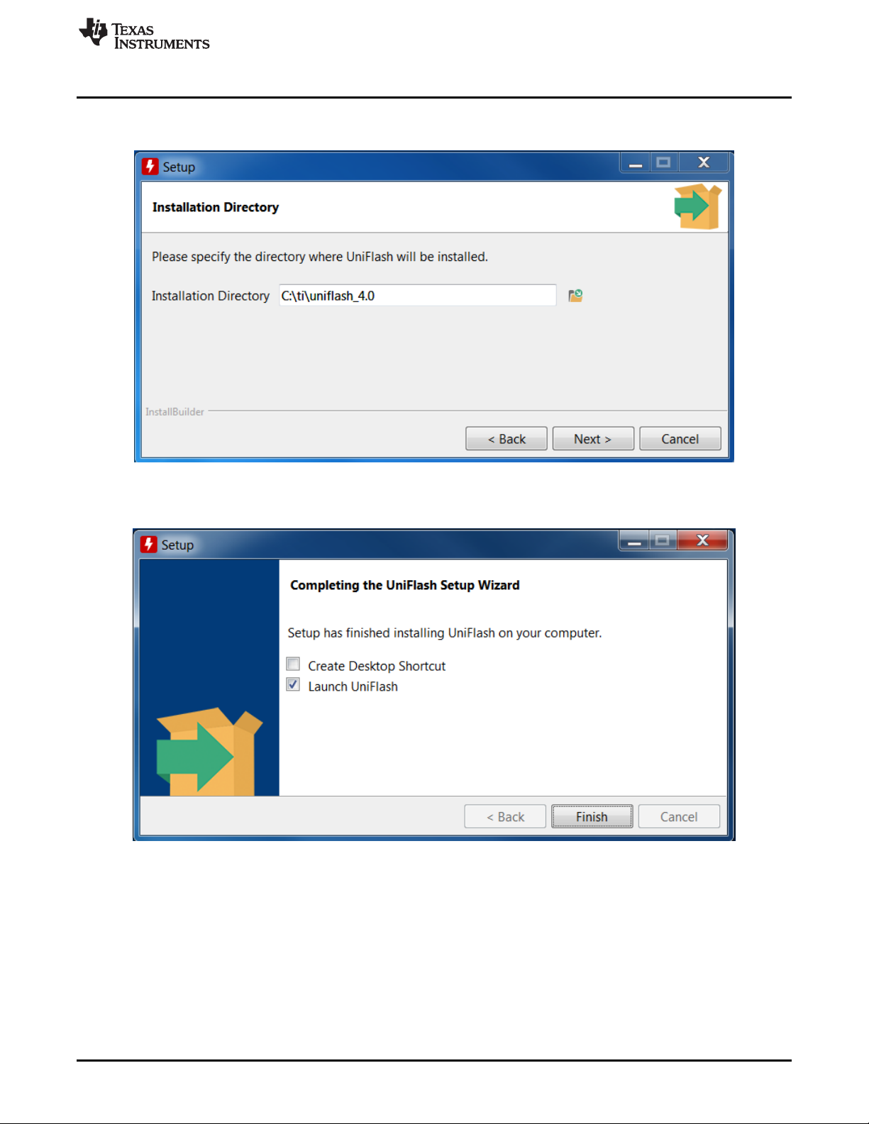
3. Choose the desired path in the Installation Directory field to place the package as shown in
UniFlash Tool
Figure 1-2, else the default is chosen.
Figure 1-2. Select Install Path
4. Proceed with the installation, and when done click Finish as shown in Figure 1-3.
Figure 1-3. Complete Installation
SWRU461B–February 2017–Revised June 2018
Submit Documentation Feedback
Copyright © 2017–2018, Texas Instruments Incorporated
Download and Installation
5
Page 6
Serial Terminal
1.4 Serial Terminal
Many sample applications come with UART support for printing the debug information or the status of any
operation. Some applications require user’s input through UART, so it is advised to install a serial terminal
application. Tera Term is used for demonstration here.
1. Download Tera Term and install as described in the instructions.
2. Run the Tera Term application.
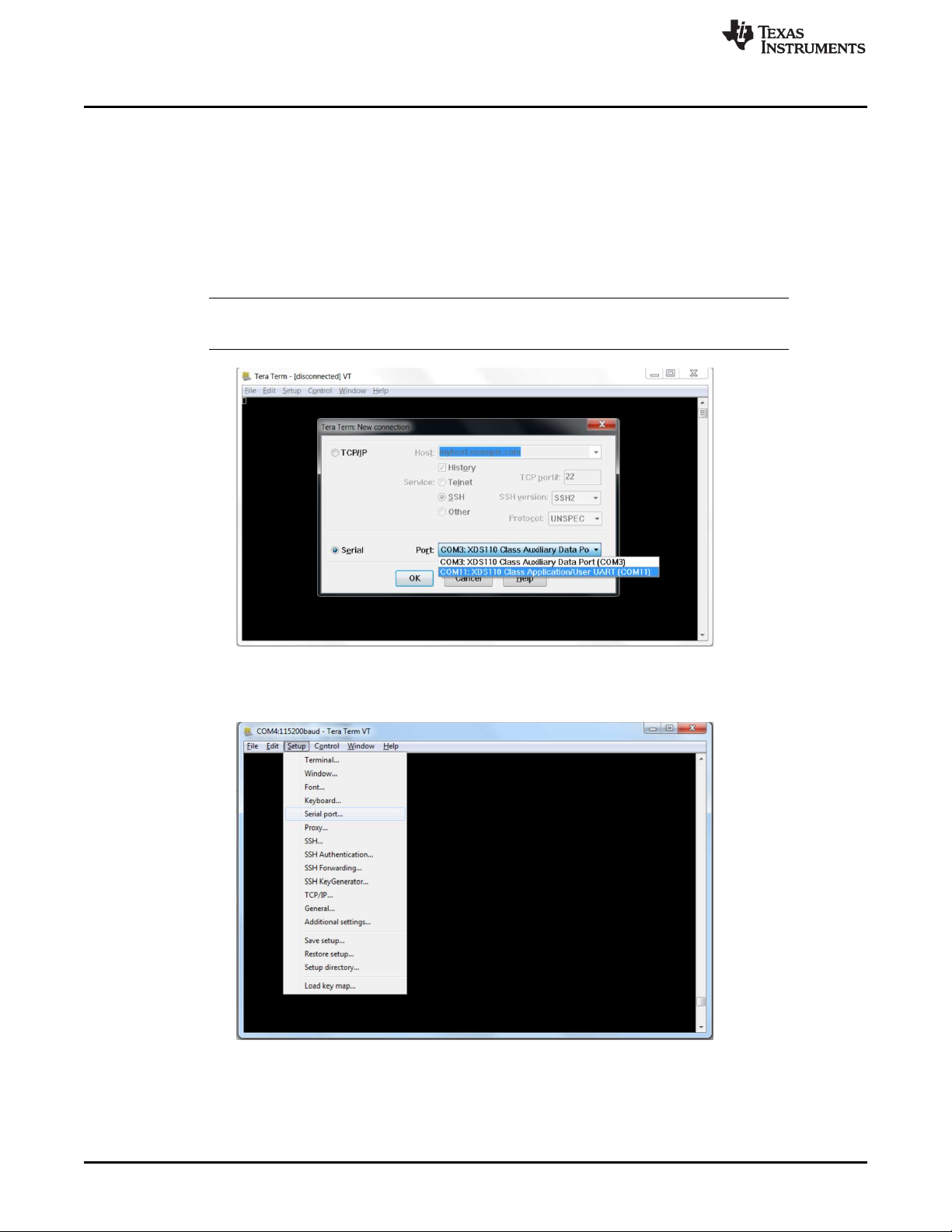
3. Select the Serial Port, then COM11: XDS110 Class Application/User UART (COM11), as shown in
Figure 1-4. Click OK to continue.
NOTE: Install the XDS110 drivers for the PC to enumerate these ports for serial terminal. See
Section 1.6 for installation of the XDS110 drivers.
www.ti.com
Figure 1-4. Select Serial Port
4. Go to Setup → Serial port, as shown in Figure 1-5.
Figure 1-5. Set up Serial Port
6
Download and Installation
Copyright © 2017–2018, Texas Instruments Incorporated
SWRU461B–February 2017–Revised June 2018
Submit Documentation Feedback
Page 7
www.ti.com
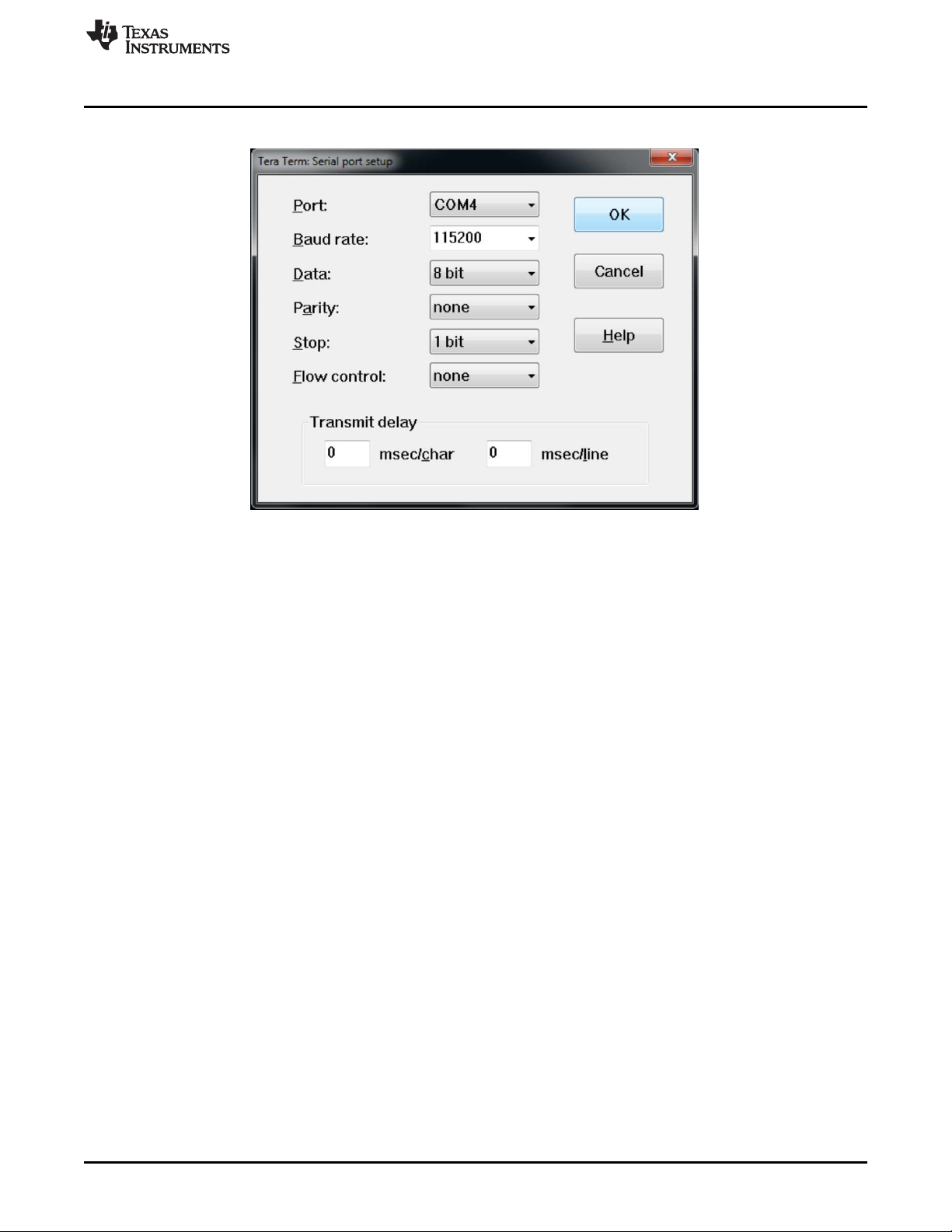
5. Configure the setting as shown in Figure 1-6. Click OK to continue.
Pin Mux Tool
Figure 1-6. Configure Settings
1.5 Pin Mux Tool
TI recommends installing the Pin Mux Tool, although it is not required to get started with your sample
application. This tool helps to configure the pin mux setting for your application. All the provided sample
applications already contain the required pin mux file (output of this tool). The latest version of this tool
can be downloaded from http://www.ti.com/tool/PINMUXTOOL. For more information on this tool, see
http://processors.wiki.ti.com/index.php/TI_PinMux_Tool_v4.
For older versions of this tool, the CC3220 device may not be listed explicitly under the supported devices.
If that is the case, choose the CC3200 device from the drop-down menu to generate the same output files
required by the CC3220 device.
1.6 XDS110 Driver Installation
XDS110 drivers must be installed before one can use the debugger or the Image Creator tool. It also
enumerates the serial terminal port, which can be used to print the debug messages over UART. The XDS
drivers can be obtained from the
http://processors.wiki.ti.com/index.php/XDS_Emulation_Software_Package#XDS110_Reset_Download.
Do the following steps for the installation.
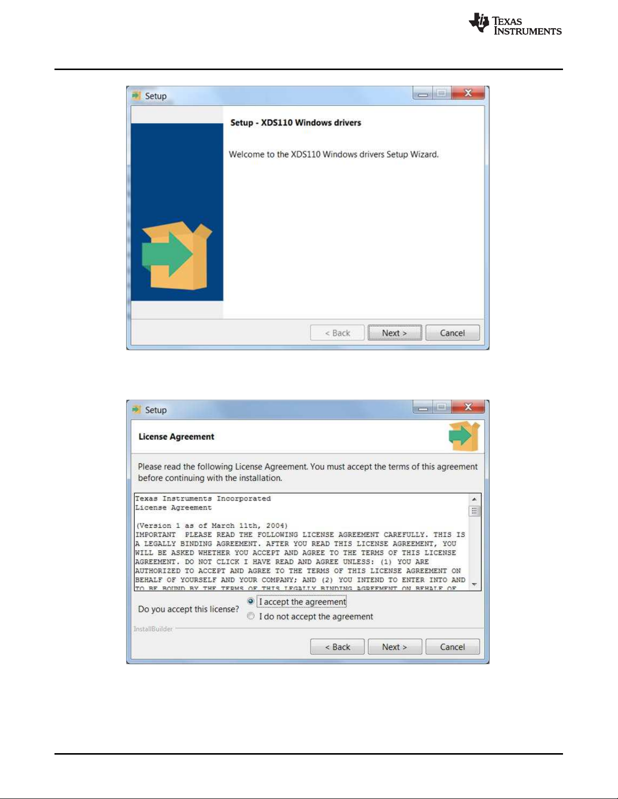
1. Run the installer in administrator mode and click Next, as shown in Figure 1-7.
SWRU461B–February 2017–Revised June 2018
Submit Documentation Feedback
Copyright © 2017–2018, Texas Instruments Incorporated
Download and Installation
7
Page 8
XDS110 Driver Installation
www.ti.com
Figure 1-7. Set up XDS110
2. Read and accept the License Agreement and click Next, as shown in Figure 1-8.
Figure 1-8. License Agreement
8
Download and Installation
Copyright © 2017–2018, Texas Instruments Incorporated
SWRU461B–February 2017–Revised June 2018
Submit Documentation Feedback
Page 9
www.ti.com
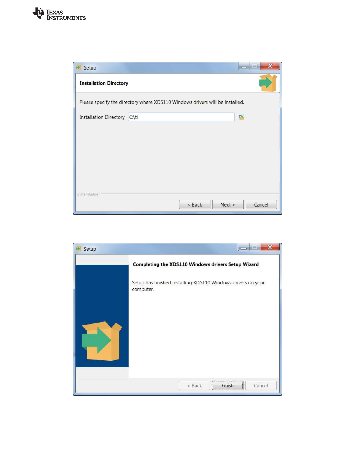
3. Specify the installation path in the Installation Directory field, as shown in Figure 1-9 (default is C:\ti),
XDS110 Driver Installation
and proceed with the installation.
Figure 1-9. Select Install Path
4. Click Finish when installation is done, as shown in Figure 1-10.
SWRU461B–February 2017–Revised June 2018
Submit Documentation Feedback
Copyright © 2017–2018, Texas Instruments Incorporated
Figure 1-10. Complete Installation
Download and Installation
9
Page 10
Debugger/IDE
1.7 Debugger/IDE
The following debugger/IDE can be used to download and debug the application image.
1.7.1 CCS
The latest CCS installer can be downloaded from http://www.ti.com/tool/ccstudio. CCS is a free tool from
TI, lets developers work with various TI devices. The SDK supports CCS version 7.0 or later.
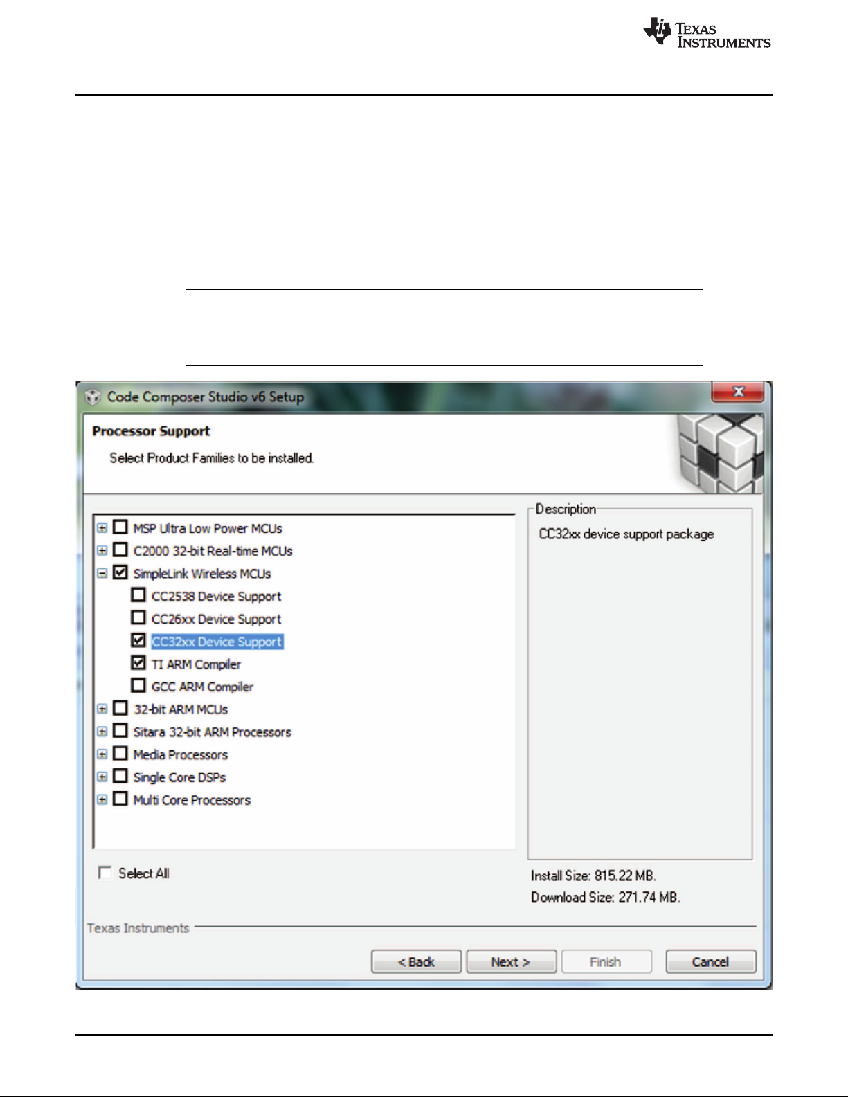
1. Double-click on the installer and follow the instruction to install this tool
2. Make sure to select the SimpleLink Wireless MCUs option for processor support, as shown in Figure 1-
11. Click Next to continue.
NOTE: If CCS is already installed for other processors (and not for SimpleLink wireless MCU), then
the installer must run again and select the SimpleLink Wireless MCUs option for processor
support this time. The rest of the installation steps will remain the same as for a new
installation:
www.ti.com
10
Download and Installation
Figure 1-11. Set up CCS
SWRU461B–February 2017–Revised June 2018
Copyright © 2017–2018, Texas Instruments Incorporated
Submit Documentation Feedback
Page 11
www.ti.com
1.7.1.1 CCS Linux Patch for CC3220 Device Variants
In case the Linux®version of CCS is being used and the CC3220 variant is not listed within the target
devices, the following patch should be applied:
1. Copy the content of the <sdk-installation-path>\tools\ccs_patch\ccs\ folder into
<ccs_installation_dir>\ccs_base.
2. Click to merge the folders with existing ones when prompted.
3. If working with a 64-bit version of CCS on Linux, delete the libFlashCC3220SF.so file in the
<ccs_installation_dir\ccs_base\DebugServer\bin\ folder and rename libFlashCC3220SF_64bit.so to
libFlashCC3220SF.so.
The future version of CCS might not need this patch. See the Release Notes (in html format)
inside <sdk-installation-path>.
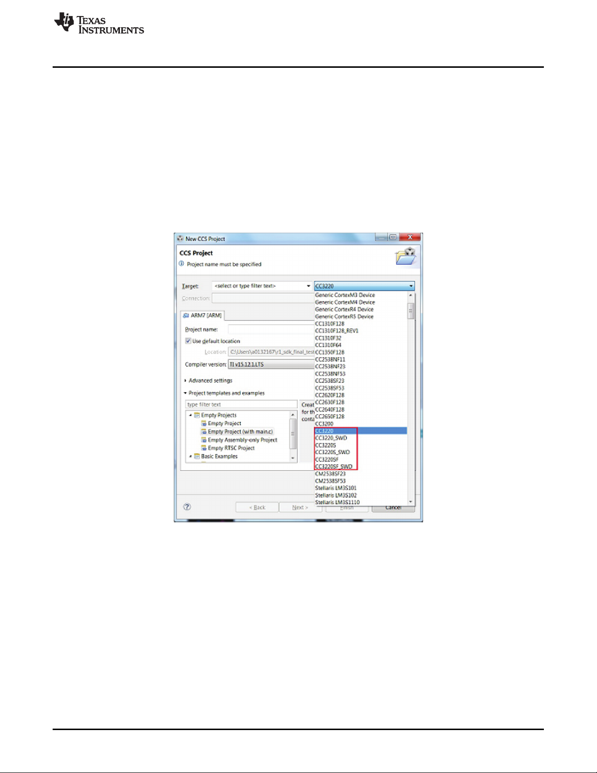
After successful patching, the device variant would be listed for CCS, as shown in Figure 1-12.
Debugger/IDE
Figure 1-12. Device Variant for CCS
SWRU461B–February 2017–Revised June 2018
Submit Documentation Feedback
Copyright © 2017–2018, Texas Instruments Incorporated
Download and Installation
11
Page 12

Debugger/IDE
1.7.2 IAR
The developer is responsible for buying the license for the IAR Embedded Workbench®tool. A trial version
can be downloaded from https://www.iar.com/iar-embedded-
workbench//#!?device=CC3220&architecture=ARM.
Double-click on the installer and follow the instruction to install this tool. For detailed IAR setup instruction,
see <sdk-installation-path>\docs\simplelink_mcu_sdk\Quick_Start_Guide.html.
1.7.3 GCC
For detailed GCC setup instruction, please refer to <sdk-installationpath>\
docs\simplelink_mcu_sdk\Quick_Start_Guide.html
1.8 Operating Systems
The CC3220 SDK currently supports TI-RTOS and FreeRTOS. Each real-time kernel port consists of
three files that contain the core kernel components and are common to every port, and one or more files
that are specific to a particular microcontroller and/or compiler. Each directory contains files specific to a
particular compiler (CCS, GCC, and IAR).
1.8.1 TI-RTOS
TI-RTOS for SimpleLink solutions is already installed in the latest CCS releases (see Section 1.7.1). IAR
users can install the TI-RTOS Support Package as a separate installer (see below).
www.ti.com
1.8.1.1 Install TI-RTOS as a Separate Installer
The latest TI-RTOS support package for SimpleLink devices can be downloaded and installed from
http://www.ti.com/tool/ti-rtos.
1.8.2 FreeRTOS
The following are the instructions to add the FreeRTOS support.
1. Download FreeRTOS official version 9 from
https://sourceforge.net/projects/freertos/files/latest/download?source=files.
2. Install the software under C:/
3. Copy the content of the patch (CCS, GCC, and IAR folders), and paste it at
C:/FreeRTOSv9.0.0/FreeRTOS/Source/portable.
4. Modify the FreeRTOS directory name from FreeRTOSv9.0.0 to FreeRTOSv9.0.0a
For IAR users, there is a manual fix that need to be done on top of the project , please change the
following:
1. Right click on the project.
2. Select Linker from the category on the left.
3. Go to the Library tab.
4. Select the checkbox Override default program entry
5. Select Entry symbol and enter resetISR in the text box.
12
Download and Installation
SWRU461B–February 2017–Revised June 2018
Copyright © 2017–2018, Texas Instruments Incorporated
Submit Documentation Feedback
Page 13

Chapter 2
SWRU461B–February 2017–Revised June 2018
Execute your First Application
The SDK supports the following device variants:
• CC3220 – Base variant
• CC3220S – CC3220 + MCU security
• CC3220SF – CC3220S + internal flash
The SDK is packed with precompiled binaries for several networking and peripheral examples. By default,
the sample applications are built for the CC3220SF variant. The user can easily compile the same
applications for the other variants just by selecting them in the project properties. See Section 2.1 to
compile the sample application for the required device variant.
This document uses Network Terminal as the reference application. The Network Terminal application
provides a CLI (command line interface over UART connection) that lets users activate basic SimpleLink
operations such as triggering a WLAN scan, connecting to a local access point (or setting an access point
or Wi-Fi-Direct connection), and performing networking services such as PING, MDNS, or data transfer
over TCP/UDP sockets. The application also enables configuration of Wake-On-WLAN filters and scan
policy and lets the user put the device in a transceiver mode for testing TX and RX operations.
This example uses a real-time operating system (TI-RTOS or FreeRTOS). The following instructions will
use the CC3220SF device and TI-RTOS, but can be easily changed to other combination, by:
• Selecting the CC3220S device-specific directory (CC3220S_LAUNCHXL instead of
CC3220SF_LAUNCHXL)
or
• Selecting sample project for FreeRTOS (for example,
network_terminal_CC3220SF_LAUNCHXL_freertos_ccs instead of
network_terminal_CC3220SF_LAUNCHXL_tirtos_ccs)
SWRU461B–February 2017–Revised June 2018
Submit Documentation Feedback
Copyright © 2017–2018, Texas Instruments Incorporated
Execute your First Application
13
Page 14

CCS
2.1 CCS
2.1.1 Import and Configure Project
1. Open CCS.
2. Choose Project → Import CCS Eclipse Projects from the menu.
3. Select the Browse button in the Import CCS Eclipse Projects dialog, as shown in Figure 2-1, and select
the directory <sdk-installation-path>\examples\os\CC3220SF_LAUNCHXL\demos (use relative path of
CC3220S if needed).
www.ti.com
14
Execute your First Application
Figure 2-1. Select CCS Projects to Import
SWRU461B–February 2017–Revised June 2018
Copyright © 2017–2018, Texas Instruments Incorporated
Submit Documentation Feedback
Page 15

www.ti.com
4. Select the network_terminal_CC3220SF_LAUNCHXL_tirtos_ccs project and click Finish (this will
CCS
automatically import also the dependent tirtos_builds_CC3220SF_LAUNCHXL_custom_ccs project), as
shown in Figure 2-2. For any library import (such as simplink or driverlib), do not check the Copy
projects into workspace checkbox. This breaks the link from the libraries to their dependencies. The
network terminal project is automatically copied to the workspace.
Figure 2-2. Select wlan_station Projects
NOTE: By default, for all reference examples the option to copy a project to the workspace is
enforced in CCS, because CCS copies the application-specific files to the workspace
location. Any modification done to these files is reflected only in the copied versions (not in
the original files in the SDK installation directory). To remove this enforcement, delete the
.ccsimportspec from the folder of the project.
SWRU461B–February 2017–Revised June 2018
Submit Documentation Feedback
Copyright © 2017–2018, Texas Instruments Incorporated
Execute your First Application
15
Page 16

CCS
www.ti.com
5. Select the tirtos_builds_CC3220SF_LAUNCHXL_custom_ccs project in Project Explorer, and select
Project → Properties from the menu. Under General, select the RTSC tab, as shown in Figure 2-3.
Make sure the latest versions of XDCtools and MCPI for CC32XX solutions are selected. Verify the
same is configured for network_terminal_CC3220SF_LAUNCHXL_freertos_ccs.
16
Figure 2-3. Select tirtos_config Project
6. Select the network_terminal_CC3220SF_LAUNCHXL_freertos_ccs project and build it.
7. Right-click on the project (Project Explorer → network_terminal_CC3220SF_LAUNCHXL_freertos_ccs)
and click on rebuild project.
8. The preceding steps will generate the application binaries under
<workspace>\network_terminall_CC3220SF_LAUNCHXL_tirtos_ccs:
• .out – to be used when downloading with the CCS debugger.
• .bin – to be used when programming with the Uniflash.
In addition, the folder will include the target map file and the compiled object files.
9. See Section 2.4 to download the application using the Image Creator tool.
10. See Chapter 3 to execute the application from the debugger.
NOTE: By default, the application is compiled for the CC3220SF variant. To build the application for
other device variants (CC3220 and CC3220S), see Section 2.1.2.
Execute your First Application
Copyright © 2017–2018, Texas Instruments Incorporated
SWRU461B–February 2017–Revised June 2018
Submit Documentation Feedback
Page 17

www.ti.com
2.1.2 Recompilation for Other Device Variants
1. Right-click on the project and select Properties.
2. Select the required device variant under General → Main → Variant, as shown in Figure 2-4.
CCS
3. Click OK.
2.2 IAR
See <sdk-installation-path>\docs\simplelink_mcu_sdk\Quick_Start_Guide.html
2.3 GCC
See <sdk-installation-path>\docs\simplelink_mcu_sdk\Quick_Start_Guide.html
SWRU461B–February 2017–Revised June 2018
Submit Documentation Feedback
Copyright © 2017–2018, Texas Instruments Incorporated
Figure 2-4. Select Device Variant
Execute your First Application
17
Page 18

Download the Application
2.4 Download the Application
You can program any application to the SFLASH using the UniFlash tool. For a CC3220SF device, the
application will be copied to the internal flash at the next device boot.
Do the procedure that follows to flash the Network Terminal application.
1. Run the UniFlash tool.
2. Select CC3120 / CC3220 from the list of devices (you may type CC3… to the search tab to filter out
other devices). See Figure 2-5.
www.ti.com
18
Execute your First Application
Figure 2-5. UniFlash – Select Device
SWRU461B–February 2017–Revised June 2018
Copyright © 2017–2018, Texas Instruments Incorporated
Submit Documentation Feedback
Page 19

www.ti.com
3. Select Start Image Creator (see Figure 2-6).
Download the Application
Figure 2-6. UniFlash – Start Image Creator
SWRU461B–February 2017–Revised June 2018
Submit Documentation Feedback
Copyright © 2017–2018, Texas Instruments Incorporated
Execute your First Application
19
Page 20

Download the Application
4. Click on New Project, as shown in Figure 2-7.
www.ti.com
Figure 2-7. New Project
20
Execute your First Application
SWRU461B–February 2017–Revised June 2018
Copyright © 2017–2018, Texas Instruments Incorporated
Submit Documentation Feedback
Page 21

www.ti.com
5. Fill all the necessary fields properly. Make sure to select the correct device type (CC3220 for CC3220
Download the Application
and CC3220S device, CC3220SF for CC3220SF device) and click on Create Project, as shown in
Figure 2-8.
NOTE: Although not required for the first step of this Getting Started guide (which uses a
programmable image), TI recommends putting the device in Development mode to allow
JTAG operation so the image can be loaded by an IDE (described in Chapter 3).
Figure 2-8. Create Project
6. Click the Connect button, as shown in Figure 2-9. Make sure the serial terminal is not connected to the
device. Also, the SOP[2..0] configuration must be 010.
Figure 2-9. Connect and Disconnect
7. Once connected, click the Service Pack icon at the lower left.
NOTE: Flashing the service pack is not mandatory to develop the format of the device. However, if
the example to be debugged requires the service pack, the service pack can be programmed
with the development formatting.
8. Browse and select the service pack installed in Section 1.2.
SWRU461B–February 2017–Revised June 2018
Submit Documentation Feedback
Copyright © 2017–2018, Texas Instruments Incorporated
Execute your First Application
21
Page 22

Download the Application
2.4.1 Image Creation for Secure Device (CC3220S and CC3220SF)
1. Click on Trusted Root-Certificate Catalog on the lower-left side.
2. Uncheck the Use default Trusted Root-Certificate Catalog checkbox and select Source File (.lst) and
Signature Source File (.lst.signed.bin), available at <sdk-installation>\tools\certificate-playground, as
shown in Figure 2-10.
www.ti.com
Figure 2-10. Certificate Store
3. Select the User Files icon on lower-left side and click the Add File icon, as shown in Figure 2-11.
22
Execute your First Application
Figure 2-11. Add File
SWRU461B–February 2017–Revised June 2018
Copyright © 2017–2018, Texas Instruments Incorporated
Submit Documentation Feedback
Page 23

www.ti.com
4. Select the following certificate files from <sdk-installation>\tools\certificate-playground and click Write,
Download the Application
as shown in Figure 2-12. Repeat this operation for each certificate file (that composes a chain of trust):
• dummy-root-ca-cert
• dummy-trusted-ca-cert
• dummy-trusted-cert
Figure 2-12. Select Certificate File
SWRU461B–February 2017–Revised June 2018
Submit Documentation Feedback
Copyright © 2017–2018, Texas Instruments Incorporated
Execute your First Application
23
Page 24

Download the Application
5. Select Select MCU Image from the drop-down menu, as shown in Figure 2-13.
www.ti.com
Figure 2-13. Select MCU Image
6. Click Browse and select the application image
(<workspace>\network_terminal_CC3220SF_LAUNCHXL_tirtos_ccs\Debug\network_terminal_CC3220
SF_LAUNCHXL_tirtos_ccs.bin) to flash.
24
Execute your First Application
SWRU461B–February 2017–Revised June 2018
Copyright © 2017–2018, Texas Instruments Incorporated
Submit Documentation Feedback
Page 25

www.ti.com
7. Make sure the Secure, Failsafe and Public Write checkboxes are checked, and select the other files.
Download the Application
• Select Private Key File Name from the drop-down menu and browse the dummy-trusted-cert-key
file available at <sdk-installation>\tools\cc32xx_tools\certificate-playground. Select the available
certificate filename from the Certification File Name drop-down menu, as shown in Figure 2-14,
and click Write.
Figure 2-14. Select Certificate Filename
8. Browse and select the service pack installed in Section 1.2.
9. Click on the icon.
SWRU461B–February 2017–Revised June 2018
Submit Documentation Feedback
Copyright © 2017–2018, Texas Instruments Incorporated
Execute your First Application
25
Page 26

Download the Application
10. Click on Program Image (Create & Program), as shown in Figure 2-15. This step might take a minute.
www.ti.com
Figure 2-15. Generate Image
26
Execute your First Application
SWRU461B–February 2017–Revised June 2018
Copyright © 2017–2018, Texas Instruments Incorporated
Submit Documentation Feedback
Page 27

www.ti.com
2.4.2 Image Creation for Nonsecure Device (CC3220)
1. Click on User Files icon on bottom left.
2. Select Select MCU Image from the Action drop-down menu, as shown in Figure 2-16.
Download the Application
Figure 2-16. Select MCU Image
3. Click Browse and select the application image to flash
SWRU461B–February 2017–Revised June 2018
Submit Documentation Feedback
Copyright © 2017–2018, Texas Instruments Incorporated
Execute your First Application
27
Page 28

Download the Application
4. Uncheck the Secure checkbox. No other parameter needs to be updated. Click Write, as shown in
Figure 2-17.
www.ti.com
5. Click on the icon.
Figure 2-17. Save Image
28
Execute your First Application
SWRU461B–February 2017–Revised June 2018
Copyright © 2017–2018, Texas Instruments Incorporated
Submit Documentation Feedback
Page 29

www.ti.com
6. Click on Program Image (Create & Program), as shown in Figure 2-18. This step might take a minute.
Launching the Application
2.5 Launching the Application
Once the image programming is complete, the application can be launched.
1. Open serial terminal and connect to the device port (as described in Section 1.4).
2. Press the Reset button on the LaunchPad development kit. During the boot process, the new image
will be detected and loaded to CC3220 internal memory (RAM in case of CC3220R and CC3220S, or
flash in case of CC3220SF) and will be executed.
Figure 2-18. Generate Image
SWRU461B–February 2017–Revised June 2018
Submit Documentation Feedback
Copyright © 2017–2018, Texas Instruments Incorporated
Execute your First Application
29
Page 30

Using the Application
2.6 Using the Application
If the CC3220 device successfully completes all steps, the serial output appears as shown in Figure 2-19.
www.ti.com
Figure 2-19. Serial Output: Network Terminal
30
Execute your First Application
SWRU461B–February 2017–Revised June 2018
Copyright © 2017–2018, Texas Instruments Incorporated
Submit Documentation Feedback
Page 31

www.ti.com
1. Now the user can type any of the menu commands. Typing a command will show its usage format.
Using the Application
See Figure 2-20 for a scan example.
Figure 2-20. Serial Output: Scan Usage
SWRU461B–February 2017–Revised June 2018
Submit Documentation Feedback
Copyright © 2017–2018, Texas Instruments Incorporated
Execute your First Application
31
Page 32

Using the Application
2. Figure 2-21 shows a successful scan execution (after typing scan –n 10).
www.ti.com
Figure 2-21. Serial Output: Scan Execution
32
Execute your First Application
SWRU461B–February 2017–Revised June 2018
Copyright © 2017–2018, Texas Instruments Incorporated
Submit Documentation Feedback
Page 33

www.ti.com
3. Continue and explore the Network Terminal available commands. Typing help will show the list of
Using the Application
available commands, as shown in Figure 2-22.
Figure 2-22. Serial Output: Help
SWRU461B–February 2017–Revised June 2018
Submit Documentation Feedback
Copyright © 2017–2018, Texas Instruments Incorporated
Execute your First Application
33
Page 34

The CC3220 SDK supports CCS 6.2.0, IAR 7.50, and GCC IDE/compiler. This section assumes that the
application has been configured and rebuilt according to the requirement.
3.1 Prerequisites
• Ensure that the selected device variant is one of the CC3220, CC3220S, or CC3220SF devices, which
should be listed under the Properties → General → Variant drop-down menu. If not, see
Section 1.7.1.1 for patching the IDE to display these device variants on the CCS version of Linux.
• To debug the secure devices, the SFLASH should be development formatted to enable the JTAG
connectivity. See Section 3.2.
• If you are downloading the image from the debugger rather than debugging the image loaded by
bootloader or UniFlash tool, ensure the following:
– For the CC3220SF variant, define __SF_DEBUG__ in the list of predefined symbols and recompile
the application. Predefined symbols for various IDEs are located at:
• CCS: Project → Properties → Build → ARM Compiler → Predefined Symbols
• IAR: Project → Options → C/C++ Compiler → Preprocessor → Defined Symbols
• GCC: Add CFLAGS+=-D__SF__DEBUG in the makefile.
This flag will add a header to the application binary that instructs the bootloader to use the internal
flash image rather than override it with an image from the serial flash.
• Ensure that the SOP[2..0] configuration on the LaunchPad is set to:
– 010 for 4-wire JTAG
– 001 for 2-wire SWD
Chapter 3
SWRU461B–February 2017–Revised June 2018
Use the Debugger/IDE
NOTE: Regardless of whether debugging in JTAG or SWD mode, for the development format of
SFLASH, the SOP mode must be 010. To debug through SWD, change the SOP to 001
after development formatting.
3.2 Development Formatting for SFLASH
When debugging for secure variants, the device must be put into development mode (using the UniFlash).
If this was not done before, repeat the procedure in Section 2.4 to program the SFLASH but make sure
that the device is set to “Develop” mode. Follow the Image Creation for Secure Device. The MCU image
can be eliminated from the procedure. When using the Develop mode, the MAC address of the device
must be programmed. The UniFlash tool does this automatically by reading the MAC address after the
device is connected and then programming the same value; however, this requires the user to connect to
the device first and then program the image.
34
Use the Debugger/IDE
Copyright © 2017–2018, Texas Instruments Incorporated
SWRU461B–February 2017–Revised June 2018
Submit Documentation Feedback
Page 35

www.ti.com
3.3 CCS
3.3.1 Rebuild the SimpleLink™ Library for Debug Configuration
The SimpleLink library is already compiled for both FreeRTOS and TI-RTOS (both archive files are
available in corresponding directories under <sdk-installation-path>\source\ti\drivers\net\wifi\ccs\).
If from any reason the SimpleLink library must be rebuilt, the Build Configuration must be specified for the
right OS (as seen in Figure 3-1).
1. Choose the relevant debug configuration (os_debug for getting started with WLAN station) from Project
→ Build Configurations → Set Active, as shown in Figure 3-1.
CCS
Figure 3-1. Select Debug Configuration
2. Compile the SimpleLink library for the selected configuration.
3. Rebuild the application.
SWRU461B–February 2017–Revised June 2018
Submit Documentation Feedback
Copyright © 2017–2018, Texas Instruments Incorporated
Use the Debugger/IDE
35
Page 36

CCS
3.3.2 Download and Debug the WLAN Station Example
1. To differ the debug application from the one programmed to the flash, it is possible to make a simple
change to the application name before it is rebuilt. The application name is defined in
“network_terminal.h” - see in Figure 3-2. The change will be reflected in the first lines of the serial
output.
www.ti.com
Figure 3-2. Application Name Definition
36
Use the Debugger/IDE
SWRU461B–February 2017–Revised June 2018
Copyright © 2017–2018, Texas Instruments Incorporated
Submit Documentation Feedback
Page 37

www.ti.com
2. By default, the target configuration is defined by the application project imported in Section 2.1.1.
CCS
Navigate to View → Target Configurations, as shown in Figure 3-3, to verify that the correct
configuration is selected (see Figure 3-4).
Figure 3-3. View Target Configurations
SWRU461B–February 2017–Revised June 2018
Submit Documentation Feedback
Copyright © 2017–2018, Texas Instruments Incorporated
Use the Debugger/IDE
37
Page 38

CCS
www.ti.com
38
Figure 3-4. Select Target Configuration
3. Set this new configuration as the default by right-clicking on the filename and selecting Set as Default
(see Figure 3-4).
4. Launch serial terminal and configure it as specified in Section 1.4.
Use the Debugger/IDE
Copyright © 2017–2018, Texas Instruments Incorporated
SWRU461B–February 2017–Revised June 2018
Submit Documentation Feedback
Page 39

www.ti.com
5. Launch the application. Select the network_terminal_CC3220SF_LAUNCHXL_tirtos_ccs project in
IAR
Project Explorer and click on the debug icon, as shown in Figure 3-5, to download code to the device
and begin debugging. Press F8 to begin execution.
6. Follow instruction in Section 2.6.
3.4 IAR
See <sdk-installation-path>\docs\cc3220\CC3220_SDK_IAR_project_setup_guide.html.
3.5 GCC
GCC is not supported in the demos of this release.
Figure 3-5. Debug Network Terminal
SWRU461B–February 2017–Revised June 2018
Submit Documentation Feedback
Copyright © 2017–2018, Texas Instruments Incorporated
Use the Debugger/IDE
39
Page 40

Revision History
www.ti.com
Revision History
Changes from A Revision (December 2017) to B Revision ........................................................................................... Page
• Updated CC3220 SDK package URL................................................................................................... 4
40
Revision History
SWRU461B–February 2017–Revised June 2018
Copyright © 2017–2018, Texas Instruments Incorporated
Submit Documentation Feedback
Page 41

IMPORTANT NOTICE FOR TI DESIGN INFORMATION AND RESOURCES
Texas Instruments Incorporated (‘TI”) technical, application or other design advice, services or information, including, but not limited to,
reference designs and materials relating to evaluation modules, (collectively, “TI Resources”) are intended to assist designers who are
developing applications that incorporate TI products; by downloading, accessing or using any particular TI Resource in any way, you
(individually or, if you are acting on behalf of a company, your company) agree to use it solely for this purpose and subject to the terms of
this Notice.
TI’s provision of TI Resources does not expand or otherwise alter TI’s applicable published warranties or warranty disclaimers for TI
products, and no additional obligations or liabilities arise from TI providing such TI Resources. TI reserves the right to make corrections,
enhancements, improvements and other changes to its TI Resources.
You understand and agree that you remain responsible for using your independent analysis, evaluation and judgment in designing your
applications and that you have full and exclusive responsibility to assure the safety of your applications and compliance of your applications
(and of all TI products used in or for your applications) with all applicable regulations, laws and other applicable requirements. You
represent that, with respect to your applications, you have all the necessary expertise to create and implement safeguards that (1)
anticipate dangerous consequences of failures, (2) monitor failures and their consequences, and (3) lessen the likelihood of failures that
might cause harm and take appropriate actions. You agree that prior to using or distributing any applications that include TI products, you
will thoroughly test such applications and the functionality of such TI products as used in such applications. TI has not conducted any
testing other than that specifically described in the published documentation for a particular TI Resource.
You are authorized to use, copy and modify any individual TI Resource only in connection with the development of applications that include
the TI product(s) identified in such TI Resource. NO OTHER LICENSE, EXPRESS OR IMPLIED, BY ESTOPPEL OR OTHERWISE TO
ANY OTHER TI INTELLECTUAL PROPERTY RIGHT, AND NO LICENSE TO ANY TECHNOLOGY OR INTELLECTUAL PROPERTY
RIGHT OF TI OR ANY THIRD PARTY IS GRANTED HEREIN, including but not limited to any patent right, copyright, mask work right, or
other intellectual property right relating to any combination, machine, or process in which TI products or services are used. Information
regarding or referencing third-party products or services does not constitute a license to use such products or services, or a warranty or
endorsement thereof. Use of TI Resources may require a license from a third party under the patents or other intellectual property of the
third party, or a license from TI under the patents or other intellectual property of TI.
TI RESOURCES ARE PROVIDED “AS IS” AND WITH ALL FAULTS. TI DISCLAIMS ALL OTHER WARRANTIES OR
REPRESENTATIONS, EXPRESS OR IMPLIED, REGARDING TI RESOURCES OR USE THEREOF, INCLUDING BUT NOT LIMITED TO
ACCURACY OR COMPLETENESS, TITLE, ANY EPIDEMIC FAILURE WARRANTY AND ANY IMPLIED WARRANTIES OF
MERCHANTABILITY, FITNESS FOR A PARTICULAR PURPOSE, AND NON-INFRINGEMENT OF ANY THIRD PARTY INTELLECTUAL
PROPERTY RIGHTS.
TI SHALL NOT BE LIABLE FOR AND SHALL NOT DEFEND OR INDEMNIFY YOU AGAINST ANY CLAIM, INCLUDING BUT NOT
LIMITED TO ANY INFRINGEMENT CLAIM THAT RELATES TO OR IS BASED ON ANY COMBINATION OF PRODUCTS EVEN IF
DESCRIBED IN TI RESOURCES OR OTHERWISE. IN NO EVENT SHALL TI BE LIABLE FOR ANY ACTUAL, DIRECT, SPECIAL,
COLLATERAL, INDIRECT, PUNITIVE, INCIDENTAL, CONSEQUENTIAL OR EXEMPLARY DAMAGES IN CONNECTION WITH OR
ARISING OUT OF TI RESOURCES OR USE THEREOF, AND REGARDLESS OF WHETHER TI HAS BEEN ADVISED OF THE
POSSIBILITY OF SUCH DAMAGES.
You agree to fully indemnify TI and its representatives against any damages, costs, losses, and/or liabilities arising out of your noncompliance with the terms and provisions of this Notice.
This Notice applies to TI Resources. Additional terms apply to the use and purchase of certain types of materials, TI products and services.
These include; without limitation, TI’s standard terms for semiconductor products http://www.ti.com/sc/docs/stdterms.htm), evaluation
modules, and samples (http://www.ti.com/sc/docs/sampterms.htm).
Mailing Address: Texas Instruments, Post Office Box 655303, Dallas, Texas 75265
Copyright © 2018, Texas Instruments Incorporated
 Loading...