

CC2431
System-on-Chip for 2.4 GHz ZigBee
™/
Applications
• ZigBee™ systems
• 2.4 GHz IEEE 802.15.4 systems
• Home/building automation
• Industrial Control and Monitoring
• Low power wireless sensor networks
• Access Control
Product Description
The
CC2431
for wireless sensor networking ZigBee™ /
802.15.4 solutions with location detection
engine hardware onboard allowing location
accuracy of around 3 meters or less. It
enables ZigBee™ nodes to be built with very
low total bill-of-material costs. The
combines the excellent performance of the
leading
industry-standard enhanced 8051 MCU, 128
KB flash memory, 8 KB RAM and many other
powerful features. Combined with the industry
leading ZigBee™ protocol stack (Z-Stack™)
from Figure 8 Wireless / Chipcon, the
provides the market’s most competitive
ZigBee™ solution.
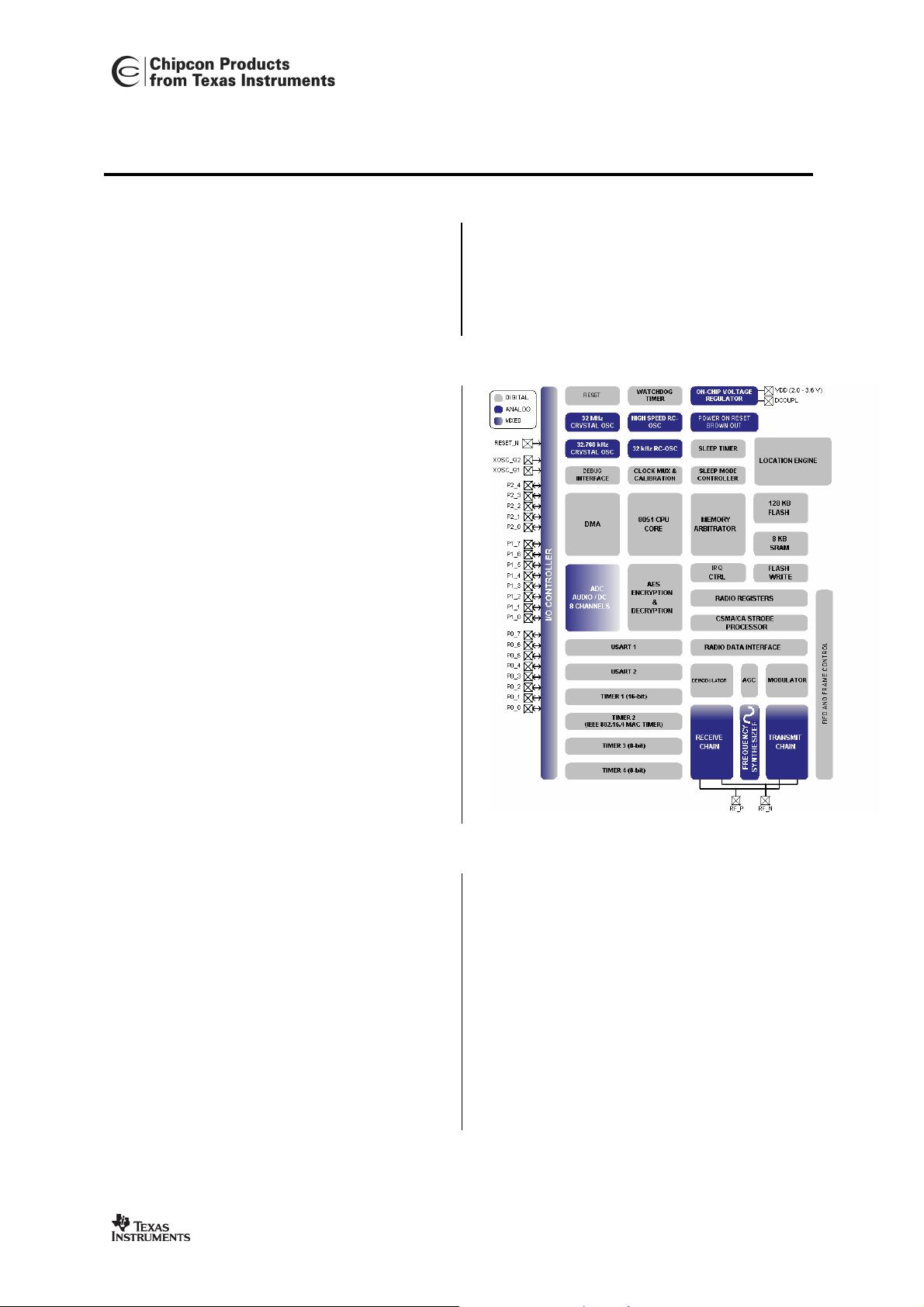
is a true System-On-Chip (SOC)
CC2431
CC2420
RF transceiver with an
CC2431
IEEE 802.15.4 with Location Engine
• PC peripherals
• Set-top boxes and remote controls
• Consumer Electronics
• Container/Vehicle Tracking
• Active RFID
• Inventory Control
CC2431
The
ultra low power consumption is required. This
is achieved by various operating modes. Short
transition times between these modes further
ensure low power consumption.
is highly suited for systems where
Key Features
• Location Engine accurately calculates
the location of a node in a network
• High performance and low power
8051 microcontroller core.
• 2.4 GHz IEEE 802.15.4 compliant RF
transceiver (industry leading
radio core).
• Excellent receiver sensitivity and
robustness to interferers
• 128 KB in-system programmable flash
• 8 KB RAM, 4 KB with data retention in
all power modes
This data sheet contains preliminary data, and supplementary data will be published at a later date. Chipcon
reserves the right to make changes at any time without notice in order to improve design and supply the best
possible product. The product at this point is not fully qualified.
CC2431 PRELIMINARY Data Sheet (Rev. 1.01) SWRS034A Page 1 of 13
CC2420
• Powerful DMA functionality
• Very few external components
• Only a single crystal needed for mesh
network systems
• Low current consumption (RX: 27mA,
TX: 25mA, microcontroller running at
32 MHz)
• Only 0.9µA current consumption in
power-down mode, where external
interrupts or the RTC can wake up the
system

Key Features (continued)
• Less than 0.6µA current consumption
in power-down mode, where external
interrupts can wake up the system
• Very fast transition times from lowpower modes to active mode enables
ultra low average power consumption
in low duty-cycle systems
• CSMA/CA hardware support
• Wide supply voltage range (2.0V –
3.6V)
• Digital RSSI/ LQI support
• Battery monitor and temperature
sensor
• 8-14 bits ADC with up to eight inputs
CC2431
• 128-bit AES security coprocessor
• Two powerful USARTs with support
for several serial protocols.
• Hardware debug support
• Watchdog timer
• One IEEE 802.15.4 MAC Timer, one
general 16-bit timer and two 8-bit
timers
• RoHS compliant 7x7mm QLP48
package
• 21 general I/O pins, two with 20mA
sink/source capability
• Powerful and flexible development
tools available
Note:
The CC2431 and the CC2430 are pin compatible, and the MCU and RF parts of the
CC2430-F128 are identical to the CC2431 except the Location Engine. This data sheet
complements the CC2430 data sheet with a description of the Location Engine. For
complete information about the CC2431, please refer to the CC2430 data sheet in
addition to this data sheet.
CC2431 PRELIMINARY Datasheet (Rev. 1.01) SWRS034A
Page 2 of 13

CC2431
Table Of Contents
1 REGISTER CONVENTIONS ................................................................................................................. 4
2 LOCATION ENGINE .............................................................................................................................. 5
2.1 LOCATION ENGINE OPERATION ................................................................................................................... 5
2.2 LOCATION ENGINE REGISTERS .................................................................................................................. 10
3 ORDERING INFORMATION .............................................................................................................. 12
4 GENERAL INFORMATION ................................................................................................................ 12
4.1 DOCUMENT HISTORY................................................................................................................................. 12
4.2 PRODUCT STATUS DEFINITIONS ................................................................................................................. 12
4.3 DISCLAIMER .............................................................................................................................................. 13
4.4 TRADEMARKS ............................................................................................................................................ 13
4.5 LIFE SUPPORT POLICY ............................................................................................................................... 13
CC2431 PRELIMINARY Datasheet (Rev. 1.01) SWRS034A Page 3 of 13

CC2431
1 Register conventions
Each RF register is described in a separate table. The table heading is given in the following
format:
REGISTER NAME (XDATA Address)
In the register descriptions, each register bit is shown with a symbol indicating the access
mode of the register bit. The register values are always given in binary notation unless
prefixed by ‘0x’ which indicates hexadecimal notation.
Symbol Access Mode
R/W Read/write
R Read only
R0 Read as 0
R1 Read as 1
W Write only
W0 Write as 0
W1 Write as 1
H0 Hardware clear
H1 Hardware set
Table 1: Register bit conventions
CC2431 PRELIMINARY Datasheet (Rev. 1.01) SWRS034A Page 4 of 13

2 Location Engine
The Location Engine is used to estimate
the position of nodes in an ad-hoc wireless
network. Reference nodes exist with
known coordinates, typically because they
are part of an installed infrastructure.
Other nodes are blind nodes, whose
coordinates need to be estimated. These
blind nodes are often mobile and attached
to assets that need to be tracked.
The Location Engine implements a
distributed computation algorithm that
uses received signal strength indicator
(RSSI) values from known reference
nodes, such as mobile neighbor nodes
with the same Location Engine, or fixed
infrastructure nodes. Performing location
calculations at the node level reduces
network traffic and communication delays
otherwise present in a centralized
computation approach.
The Location Engine has the following
main features:
• Three to eight reference nodes
can be used for the location
estimation algorithm
• Location estimate with resolution
of 0.5 meters
• Time to estimate node location
less than 40 µs
• Location range 64 x 64 meters
• Location error can be less than 3
meters, depending on factors
described below
CC2431
To achieve the best possible accuracy one
should use antennas that have nearisotropic radiation characteristics. The
location error depends on signal
environment, deployment pattern of
reference nodes and the density of
reference nodes in a given area. In
general, having more reference nodes
available improves the accuracy of the
location estimation.
2.1 Location Engine Operation
This section describes the basic steps
required to obtain location estimates from
the Location Engine.
The Location Engine requires a set of
three to eight reference coordinates to be
input together with a set of measured
parameters. The output from the Location
Engine consists of a pair of estimated
location coordinates.
Before any input data is written, the
Location Engine must be enabled by
writing a 1 to the enable bit,
When the Location Engine is not in use,
writing a 0 to
power consumption of the CC2431 by
gating off the Engine’s clock signal.
Figure 1 shows the basic operation of the
Location Engine.
LOCENG.EN will reduce the
LOCENG.EN.
• Runs location estimation with
minimum CPU usage
CC2431 PRELIMINARY Datasheet (Rev. 1.01) SWRS034A Page 5 of 13

CC2431
LOCENG.EN=1
Load
coordinate
pairs?
yes
LOCENG.REFLD=1
no
Load reference
coordinate pairs
Loaded 8
coordinate
pairs?
yes
LOCENG.REFLD=0
LOCENG.PARLD=1
Load measured
parameter or zero for
unused reference
Loaded 10
parameters?
yes
LOCENG.PARLD=0
LOCENG.RUN=1
no
no
Wait
LOCENG.DONE=1
?
yes
Read LOCX, LOCY
and LOCMIN
LOCENG.EN=0
no
Figure 1: Location Engine Operation
CC2431 PRELIMINARY Datasheet (Rev. 1.01) SWRS034A Page 6 of 13

CC2431
2.1.1 Reference Coordinates
The Location Engine requires a set of
between three and eight reference
coordinates [x0, y0, x1, y1, … x7, y7] to be
input. The reference coordinates express
each reference nodes position in meters,
as unsigned values in the interval [0,
63.75] meters. The finest possible
resolution is 0.25 meter. The format used
is fixed-point data with the two LSBs
representing the fractional part and the
remaining six bits representing the integer
part.
Reference coordinates are loaded into the
RF register
REFCOORD. Before writing to
REFCOORD, a 1 must be written to the
register bit
that a set of reference coordinates are
being written. Once the coordinate load
process commences (
=1), eight coordinate pairs must always be
written. However, it is possible for the
Location Engine to use less than eight
reference coordinates, by marking certain
reference coordinates as unused. Zeros
can be used to fill the unused reference
coordinate slots, and they will be
interpreted as unused when 0.0 is loaded
as the RSSI value for those reference
coordinates.
The reference coordinates are written in
the order [x0, y0, x1, y1, …, x7, y7] to the
register
have been written, a 0 is written to the
register bit
2.1.2 Measured Parameters
After the reference coordinates have been
written, a set of measured parameters
must be input to the Location Engine.
These parameters consist of two radio
parameters and eight RSSI values. The
radio parameters are the values A and n.
These radio parameters are used in the
Engine’s algorithm used to find the
estimated location. The parameters A and
LOCENG.REFLD to indicate
LOCENG.REFLD
REFCOORD. After all coordinates
LOCENG.REFLD.
n can be adjusted to describe the
propagation environment in which a
network of devices will operate.
2.1.2.1 Parameter Definitions
The measured parameters are described
in this section together with how these
should be estimated.
2.1.2.1.1 Parameter A
The radio parameter A is defined as the
absolute value of the average power in
dBm received at a close-in reference
distance of one meter from the transmitter,
assuming an omni-directional radiation
pattern. For example, if the mean
received power at one meter is -40 dBm,
the parameter A is specified as 40.
The Engine expects the parameter A to be
in the range [30.0, 50.0] with precision 0.5.
The parameter A is given as an unsigned
fixed-point value where the LSB bit is the
fractional bit and the remaining bits are the
integer part. A typical value for A is 40.0.
2.1.2.1.2 Parameter n
The radio parameter n is defined as the
path loss exponent that describes the rate
at which the signal power decays with
increasing distance from the transmitter.
This decay is proportional to d
the distance between transmitter and
receiver.
The actual parameter n value written to
the Location Engine is an integer index
value selected from a lookup table shown
in Table 2.
As an example, in the case when the
value n=2.98 is found from measurements,
the closest available value of n in the
lookup table is 3.00, corresponding to
index 13. Therefore, the integer value 13
is used for the parameter n written to the
Location Engine.
Refer to section 2.1.2.1.3 in order to find
the value for n to be used.
-n
where d is
CC2431 PRELIMINARY Datasheet (Rev. 1.01) SWRS034A Page 7 of 13

x
CC2431
n index n n inde
0 1.000 16 3.375
1 1.250 17 3.500
2 1.500 18 3.625
3 1.750 19 3.750
4 1.875 20 3.875
5 2.000 21 4.000
6 2.125 22 4.125
7 2.250 23 4.250
8 2.375 24 4.375
9 2.500 25 4.500
10 2.625 26 4.625
11 2.750 27 5.000
12 2.875 28 5.500
13 3.000 29 6.000
14 3.125 30 7.000
15 3.250 31 8.000
Table 2: n parameter lookup table
The parameter n is written to the Location
Engine as an integer index in the range [0,
31] as the index is given as an integer
value with no fractional bits, e.g. the value
n = 7 is loaded as 00000111. A typical
value for n is 13.
2.1.2.1.3 Parameter Estimation
The parameters A and n can be estimated
empirically by collecting RSSI data (and
therefore path loss data) for which the
distances between the transmitting and
receiving devices are known. Figure 2 is a
scatter plot of abs(RSSI) data versus log
distance in meters. A least-squares best-fit
line is used to glean the specific values of
n
A and n for the environment in which the
data were measured:
• A is the y-intercept of the line, and
• n is the slope of the line
The data in Figure 2 give A=42.4 and
n=2.98 for that environment. Note that the
plot in this example does not show the
actual y-intercept i.e. the point on the line
where x=0.
The value of A loaded into the engine in
this case would by 42.5. The value of n
loaded into the engine, is seen to be 13
from Table 2.
CC2431 PRELIMINARY Datasheet (Rev. 1.01) SWRS034A Page 8 of 13

CC2431
95
90
85
80
75
70
Path Loss (dB)
65
60
55
50
45
2 4 6 8 10 12 14
Path Loss vs. log-dis tance for sourc e 0x85, Z=2.1082. A= 42.4103, n= 2.9773
10*log10(distance)
Figure 2: Path loss vs. log distance
2.1.2.1.4 RSSI Values
The RSSI values are the RSSI
measurements corresponding to the set of
reference coordinates. The RSSI values
are within the interval [-40 dBm, -95 dBm]
with precision 0.5 dBm. The negative sign
is removed in the value written. As an
example, in the case where the value
RSSI = -50.35 dB, this would be written
into the location engine as 50.5.
Note that a value of 0.0 must be written as
RSSI value for unused reference
coordinates. The engine will not function
correctly if only some of the parameters
are loaded.
2.1.2.2 Loading Parameters
All measured parameters are loaded into
the RF register
MEASPARM, a 1 must be written to the
to
register bit
MEASPARM. Before writing
LOCENG.PARLD to indicate
that a set of measured parameters are
being written. Once the parameter load
process commences (
LOCENG.PARLD
=1), all ten parameters must be written.
The measured parameters must be written
in the order [A, n, rssi0, rssi1, … rssi7] to
CC2431 PRELIMINARY Datasheet (Rev. 1.01) SWRS034A Page 9 of 13
MEASPARM register. Once the
the
parameter load process commences
(
LOCENG.PARLD =1) it must be
completed. Eight RSSI values must be
written, so any unused slots must be
written as zeros. After all ten parameters
have been written, a 0 must be written to
the register bit
LOCENG.PARLD.
2.1.3 Location Estimation
The estimated location coordinates are
given in meters in the interval [0.0, 63.5]
with precision 0.5 m. The data format uses
the LSB bit as the fractional part.
When reference coordinates and
measured parameters have been loaded,
the location estimate is calculated by
writing 1 to the
LOCENG.RUN register bit.
The estimated coordinates can be read
from the
LOCX and LOCY registers when
LOCENG.DONE is set to 1. This occurs
1200 system clock cycles (16/32 MHz)
after
LOCENG.RUN was set to 1. The
Location Engine does not produce any
interrupt requests.
The estimated coordinates remain valid in
LOCX and LOCY registers until new
the

CC2431
results have been calculated or until a
reset.
Note that
operation of the Location Engine.
2.2 Location Engine Registers
This section describes the RF registers
associated with the Location Engine.
These registers are:
XDATA
Address
0xDF55 REFCOORD Reference coordinates input
0xDF56 MEASPARM Measured parameters input
0xDF57 LOCENG Location Engine control and status
0xDF58 LOCX Location estimate X coordinate
0xDF59 LOCY Location estimate Y coordinate
0xDF5A LOCMIN Minimum function estimate
0xDF60 CHVER Chip Version
0xDF61 CHIPID Chip Identification
LOCENG.EN must be 1 during
LOCENG Location Engine
•
control and status
REFCOORD Reference
•
coordinates input
•
MEASPARM Measured
parameters input
Table 3 : Overview of Location Engine RF registers
Register name Description
The RF registers reside in XDATA memory
space. Table 3 gives an overview of
register addresses while the remaining
tables in this section describe each
register in detail. Refer also to section 1
for Register conventions.
For the remaining RF registers refer to the
CC2430 Data Sheet.
LOCX Location estimate
•
X coordinate
LOCY Location estimate
•
Y coordinate
•
LOCMIN Minimum function
estimate
Bit Name Reset R/W Description
7:0 REFCOORD 0 R/W
Table 4: Register REFCOORD (0xDF55)
Bit Name Reset R/W Description
7:0 MEASPARM 0 R/W
Table 5: Register MEASPARM (0xDF56)
CC2431 PRELIMINARY Datasheet (Rev. 1.01) SWRS034A Page 10 of 13
Location Engine reference coordinate [x0, y0, x1, y1, … x7,
y7]
Location Engine measured parameters of channel and
reference nodes [A, n, rssi0, rssi1, …, rssi7]

Bit Name Reset R/W Description
CC2431
7:5 - 00 R0
4 EN 0 R/W
3 DONE 0 R
2 PARLD 0 R/W
1 REFLD 0 R/W
0 RUN 0 R0W1
Reserved, read as 0.
Enable location engine
0 Disable location engine
1 Enable location engine
Estimation completed. After 1 has been written to RUN, this
bit is cleared and then set to 1 when the estimated data is
ready.
Load parameters. This bit shall be written as 1 before the
set of parameters are written to MEASPARM. Write 0 to this
bit after the last parameter has been written.
Load reference coordinates. This bit shall be written as 1
before the set of coordinates are written to REFCOORD.
Write 0 to this bit after the last coordinate has been written.
Location estimate start. This bit shall be written as 1 when
desired coordinates and parameters have been written to
REFCOORD and MEASPARM registers. Estimation
process starts when 1 is written to this bit. Always read as
0.
Table 6: Register LOCENG (0xDF57)
Bit Name Reset R/W Description
7:0 LOCX 00h R
Location estimate X coordinate.
Table 7: Register LOCX (0xDF58)
Bit Name Reset R/W Description
7:0 LOCY 00h R
Location estimate Y coordinate.
Table 8: Register LOCY (0xDF59)
Bit Name Reset R/W Description
7:0 LOCMIN 00h R
Location estimate minimum value
Table 9: Register LOCMIN (0xDF5A)
Bit Name Reset R/W Description
7:0 VERSION[7:0] 0x01 R
Chip revision number
Table 10: Register CHVER (0xDF60)
Bit Name Reset R/W Description
7:0 CHIPID[7:0] 0x89 R
Chip identification number. Always read as 0x89.
Table 11: Register CHIPID (0xDF61)
CC2431 PRELIMINARY Datasheet (Rev. 1.01) SWRS034A Page 11 of 13

3 Ordering Information
CC2431
Ordering part number Description Minimum Order
1371 CC2431-RTB1 CC2431, QLP48 package, RoHS compliant Pb-free assembly in
tubes with 43 pcs per tube, Single Chip RF Transceiver
1372 CC2431-RTR1 CC2431, QLP48 package, RoHS compliant Pb-free assembly,
tape and reel with 2500 pcs per reel, Single Chip RF Transceiver
1367 CC2431DK CC2431 ZigBee Development Kit 1
1368 CC2431ZDK Pro CC2431 ZigBee Development Kit including support and training 1
Quantity (MOQ)
43
2500
Table 12: Ordering Information
4 General Information
4.1 Document History
Revision Date Description/Changes
1.0 2005-11-30 First release
1.01 2006-05-11 Preliminary status updated
Table 13: Document History
4.2 Product Status Definitions
Data Sheet Identification Product Status Definition
Advance Information Planned or Under
Development
Preliminary Engineering Samples
and Pre-Production
Prototypes
No Identification Noted Full Production This data sheet contains the final specifications. Chipcon
Obsolete Not In Production This data sheet contains specifications on a product that has
This data sheet contains the design specifications for product
development. Specifications may change in any manner without
notice.
This data sheet contains preliminary data, and supplementary
data will be published at a later date. Chipcon reserves the right
to make changes at any time without notice in order to improve
design and supply the best possible product. The product is not
yet fully qualified at this point.
reserves the right to make changes at any time without notice in
order to improve design and supply the best possible product.
been discontinued by Chipcon. The data sheet is printed for
reference information only.
Table 14: Product Status Definitions
CC2431 PRELIMINARY Datasheet (Rev. 1.01) SWRS034A Page 12 of 13

CC2431
4.3 Disclaimer
Chipcon AS believes the information contained herein is correct and accurate at the time of this printing. However,
Chipcon AS reserves the right to make changes to this product without notice. Chipcon AS does not assume any
responsibility for the use of the described product; neither does it convey any license under its patent rights, or the rights
of others. The latest updates are available at the Chipcon website or by contacting Chipcon directly.
As far as possible, major changes of product specifications and functionality, will be stated in product specific Errata Notes
published at the Chipcon website. Customers are encouraged to sign up for the Chipcon Newsletter for the most recent
updates on products and support tools.
When a product is discontinued this will be done according to Chipcon’s procedure for obsolete products as described in
Chipcon’s Quality Manual. This includes informing about last-time-buy options. The Quality Manual can be downloaded
from Chipcon’s website.
Compliance with regulations is dependent on complete system performance. It is the customer’s responsibility to ensure
that the system complies with regulations.
The ZigBee Specification includes intellectual property rights of ZigBee Alliance member/promoter companies. Chipcon is
a ZigBee Alliance Promoter. Under the ZigBee Alliance terms of use, no part of the Specification may be used by a
company in the development of a product for sale without such company becoming a member of the ZigBee Alliance.
Therefore, the Figure 8 Wireless Z-Stack™ may only be used for commercial purposes by ZigBee Alliance member
companies. If a customer desires to use the Figure 8 Wireless Z-Stack™ or any other third party ZigBee stack together
with a product described in this datasheet, the customer is responsible for complying with the applicable ZigBee Alliance
policies. See http://www.zigbee.org.
This Chipcon product contains Flash memory code protection. However, Chipcon does not guarantee the security of this
protection. Chipcon customers using or selling these products with program code do so at their own risk and agree to fully
indemnify Chipcon AS for any damages resulting from the use or sale of such products.
Chipcon believes that the Flash memory protection used in this product is one of the most secure in the market today
when used in the intended manner and under normal conditions. However, there might be methods to breach the code
protection feature. Neither Chipcon nor any other semiconductor manufacturer can guarantee the security of their code
protection. Code protection does not mean that we are guaranteeing the product as “unbreakable”.
This Chipcon product contains hardware AES encryption. Chipcon does not guarantee the security of the key protection or
the security of the encryption scheme. Chipcon customers using or selling products with AES do so at their own risk and
agree to fully indemnify Chipcon AS for any damages resulting from the use or sale of such products.
It is the Chipcon customer's responsibility to ensure that sale or export/import of products including this Chipcon product
with AES encryption is sold with the required export/import licenses, if necessary, and does not violate any applicable
export/import and/or other trade restrictions.
4.4 Trademarks
SmartRF® is a registered trademark of Chipcon AS. SmartRF® is Chipcon's RF technology platform with RF library cells,
modules and design expertise. Based on SmartRF
as full custom ASICs based on customer requirements and this technology.
All other trademarks, registered trademarks and product names are the sole property of their respective owners.
®
technology Chipcon develops standard component RF circuits as well
4.5 Life Support Policy
This Chipcon product is not designed for use in life support appliances, devices, or other systems where malfunction can
reasonably be expected to result in significant personal injury to the user, or as a critical component in any life support
device or system whose failure to perform can be reasonably expected to cause the failure of the life support device or
system, or to affect its safety or effectiveness. Chipcon AS customers using or selling these products for use in such
applications do so at their own risk and agree to fully indemnify Chipcon AS for any damages resulting from any improper
use or sale.
© 2006, Chipcon AS. All rights reserved.
CC2431 PRELIMINARY Datasheet (Rev. 1.01) SWRS034A Page 13 of 13

IMPORTANT NOTICE
Texas Instruments Incorporated and its subsidiaries (TI) reserve the right to make corrections, modifications,
enhancements, improvements, and other changes to its products and services at any time and to discontinue
any product or service without notice. Customers should obtain the latest relevant information before placing
orders and should verify that such information is current and complete. All products are sold subject to TI’s terms
and conditions of sale supplied at the time of order acknowledgment.
TI warrants performance of its hardware products to the specifications applicable at the time of sale in
accordance with TI’s standard warranty. Testing and other quality control techniques are used to the extent TI
deems necessary to support this warranty . Except where mandated by government requirements, testing of all
parameters of each product is not necessarily performed.
TI assumes no liability for applications assistance or customer product design. Customers are responsible for
their products and applications using TI components. To minimize the risks associated with customer products
and applications, customers should provide adequate design and operating safeguards.
TI does not warrant or represent that any license, either express or implied, is granted under any TI patent right,
copyright, mask work right, or other TI intellectual property right relating to any combination, machine, or process
in which TI products or services are used. Information published by TI regarding third-party products or services
does not constitute a license from TI to use such products or services or a warranty or endorsement thereof.
Use of such information may require a license from a third party under the patents or other intellectual property
of the third party, or a license from TI under the patents or other intellectual property of TI.
Reproduction of information in TI data books or data sheets is permissible only if reproduction is without
alteration and is accompanied by all associated warranties, conditions, limitations, and notices. Reproduction
of this information with alteration is an unfair and deceptive business practice. TI is not responsible or liable for
such altered documentation.
Resale of TI products or services with statements different from or beyond the parameters stated by TI for that
product or service voids all express and any implied warranties for the associated TI product or service and
is an unfair and deceptive business practice. TI is not responsible or liable for any such statements.
Following are URLs where you can obtain information on other Texas Instruments products and application
solutions:
Products Applications
Amplifiers amplifier.ti.com Audio www.ti.com/audio
Data Converters dataconverter.ti.com Automotive www.ti.com/automotive
DSP dsp.ti.com Broadband www.ti.com/broadband
Interface interface.ti.com Digital Control www.ti.com/digitalcontrol
Logic logic.ti.com Military www.ti.com/military
Power Mgmt power.ti.com Optical Networking www.ti.com/opticalnetwork
Microcontrollers microcontroller.ti.com Security www.ti.com/security
Low Power Wireless www.ti.com/lpw Telephony www.ti.com/telephony
Video & Imaging www.ti.com/video
Wireless www.ti.com/wireless
Mailing Address: Texas Instruments
Post Office Box 655303 Dallas, Texas 75265
Copyright 2007, Texas Instruments Incorporated
 Loading...