

Page 1
CABRI GEOMETRYë II
Guidebook for Macintoshë, Windowsë, and MS-DOS
ë
Page 2

Important
Texas Instruments makes no warranty, either expressed or implied, including but not limited to any
implied warranties of merchantability and fitness for a particular purpose, regarding any programs or book
materials and makes such materials available solely on an “as-is” basis.
In no event shall Texas Instruments be liable to anyone for special, collateral, incidental, or consequential
damages in connection with or arising out of the purchase or use of these materials, and the sole and
exclusive liability of Texas Instruments, regardless of the form of action, shall not exceed the purchase
price of this equipment. Moreover, Texas Instruments shall not be liable for any claim of any kind
whatsoever against the use of these materials by any other party.
Permission to Print
Permission is hereby granted to teachers to reprint or photocopy in classroom, workshop, or seminar
quantities the pages or sheets in this work that carry a Texas Instruments copyright notice. These pages
are designed to be reproduced by teachers for use in their classes, workshops, or seminars with the
accompanying Cabri Geometry II software, provided each copy made shows the copyright notice. Such
copies may not be sold and further distribution is expressly prohibited. Except as authorized above, prior
written permission must be obtained from Texas Instruments Incorporated to reproduce or transmit this
work or portions thereof in any other form or by any other electronic or mechanical means, including any
information storage or retrieval system, unless expressly permitted by federal copyright law. Address
inquiries to Texas Instruments Incorporated, 7800 Banner Drive, Dallas, TX 75251, M/S 3918, Attention:
Manager, Business Services.
TI Product and Services Information
For more information about TI products and services, contact TI by e-mail or visit the TI calculator home
page on the world-wide web.
e-mail address:ti-cares@ti.com
internet address:http://www.ti.com/calc
Cabri Geometry II is a trademark of Université Joseph Fourier.
Macintosh is a registered trademark of Apple Computer Corporation Incorporated.
MS-DOS and Windows are registered trademarks of Microsoft Corporation.
PostScript is a registered trademark of Adobe Systems Incorporated.
1997, 1999 by Texas Instruments Incorporated. All rights reserved.
Page 3
CABRI GEOMETRY II
Guidebook
for Macintosh
and MS-DOS
ë
ë
, Windowsë,
Dive into Geometry
Page 4

About Cabri Geometry II
Cabri Geometry II lets you construct and explore geometric objects interactively.
Jean-Marie Laborde and Franck Bellemain developed Cabri Geometry II at the Institut
d'Informatique et Mathématiques Appliquées de Grenoble (IMAG), a research lab at the Université
Joseph Fourier in Grenoble, France, in cooperation with the Centre National de la Recherche
Scientifique (CNRS) and Texas Instruments.
Texas Instruments, the publisher for Cabri Geometry II in the United States and Canada, is pleased
to bring computer-based geometry to classrooms. The geometric foundation of this easy-to-use
software encourages exploring and conjecturing—from simple shapes to advanced projective and
hyperbolic geometry.
About the Developers
Jean-Marie Laborde is founder and Research Director of Laboratoire de Structures Discrètes et de
Didactique (LSD2), a research laboratory within IMAG. He graduated in mathematics at Ècole
Normale Supérieure in Paris in 1969. He earned a Ph.D. (Thèse d'État) in computer science at the
University of Grenoble in 1977. Jean-Marie began work on the Cabri II project in 1981 as an
environment for graph theory. He has devoted his research efforts to the use of geometric methods
for the study of different classes of graphs, especially hypercubes.
Franck Bellemain earned a Ph.D. in mathematics at the Université Joseph Fourier in 1992. He
began work on the Cabri II project in 1986 and is responsible for writing several versions of the
software for Macintosh, PC-compatible, and Japanese computers. His research and thesis have
been devoted to the use of technology in the classroom.
Cabri Geometry II Features
¦ Includes interactive analytic, transformational, and Euclidean geometry.
¦ Allows intuitive construction of points, lines, triangles, polygons, circles, and other basic
objects.
¦ Translates, dilates, and rotates geometric objects around geometric centers or specified points
plus reflection, symmetry, and inverse of the objects.
¦ Constructs conics easily, including ellipses and hyperbolas.
¦ Explores advanced concepts in projective and hyperbolic geometry.
¦ Annotates and measures figures (with automatic updating).
¦ Uses both Cartesian and polar coordinates.
¦ Provides for user display of the equations of geometric objects, including lines, circles,
ellipses, and coordinates of points.
¦ Allows the user to create macros for frequently repeated constructions.
¦ Lets the teacher configure tool menus to focus student activities.
¦ Checks geometric properties to test hypotheses based on Euclid’s five postulates.
¦ Hides objects used in constructions to reduce screen clutter.
¦ Differentiates objects through the use of paint-like color and line palettes.
¦ Computes a locus continuously.
¦ Illustrates the dynamic characteristics of figures through animation.
¦ Allows the user to save drawings and macros to disk.
¦ Opens geometry constructions created on the TI-92.
¦ Provides one square meter of full-size work space, and prints the 8.5 by 11.0 inches (21.59 by
27.94 cm) drawing area.
Copying permitted provided TI copyright notice is included
© 1997, 1999 Texas Instruments Incorporated
Page 5
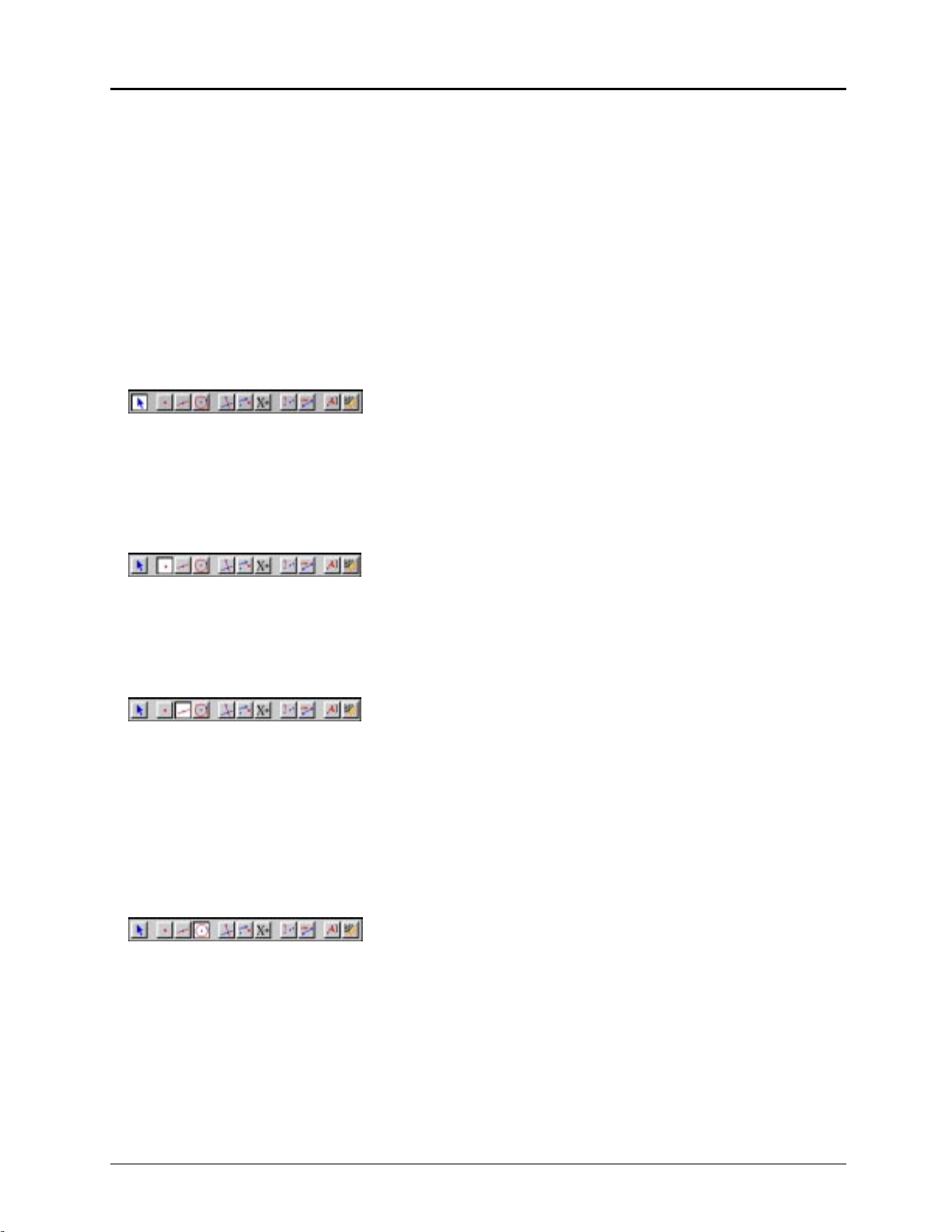
Table of Contents
About this Guidebook
CHAPTER 1: LEARNING THE BASICS
First Steps
Constructing Objects
.............................................................................
CHAPTER 2: USING THE MENUS
File Menu
Edit Menu
Options Menu
Help Menu
.............................................................................
.............................................................................
..........................................................................
.............................................................................
..................................................................
.............................................
...................................................................
...................................................
CHAPTER 3: USING THE POINTER TOOLBOX
Pointer
Rotate
Dilate
Rotate and Dilate
CHAPTER 4: USING THE POINTS TOOLBOX
................................................................................
................................................................................
.................................................................................
.......................................................................
......................................
....................................
vi
1–1
1–2
1–10
2–1
2–2
2–5
2–7
2–12
3–1
3–2
3–3
3–4
3–5
4–1
..................................................................................
Point
Point on Object
Intersection Point(s)
CHAPTER 5: USING THE LINES TOOLBOX
..................................................................................
Line
Segment
Ray
Vector
Triangle
Polygon
Regular Polygon
...............................................................................
...................................................................................
................................................................................
...............................................................................
...............................................................................
........................................................................
...................................................................
........................................
.......................................................................
CHAPTER 6: USING THE CURVES TOOLBOX
.................................................................................
Circle
...................................................................................
Arc
.................................................................................
Conic
.....................................
4–2
4–3
4–4
5–1
5–2
5–4
5–5
5–6
5–7
5–8
5–9
6–1
6–2
6–3
6–4
Copying permitted provided TI copyright notice is included
© 1997, 1999 Texas Instruments Incorporated
iii
Page 6
CHAPTER 7: USING THE CONSTRUCT TOOLBOX
...............................
7–1
Perpendicular Line
Parallel Line
Midpoint
..............................................................................
Perpendicular Bisector
Angle Bisector
Vector Sum
Compass
............................................................................
..............................................................................
Measurement Transfer
.................................................................................
Locus
Redefine Point
Redefine Object
.....................................................................
...........................................................................
..................................................................
.........................................................................
..................................................................
.........................................................................
........................................................................
CHAPTER 8: USING THE TRANSFORM TOOLBOX
Reflection
Symmetry
Translation
Rotation
Dilation
Inverse
CHAPTER 9: USING THE MACRO TOOLBOX
.............................................................................
.............................................................................
............................................................................
...............................................................................
...............................................................................
................................................................................
.....................................
...............................
7–2
7–3
7–4
7–5
7–6
7–7
7–8
7–9
7–11
7–13
7–14
8–1
8–2
8–3
8–4
8–5
8–6
8–7
9–1
How to create a macro
Initial Object
Final Object
Define Macro
...........................................................................
...........................................................................
..........................................................................
..................................................................
CHAPTER 10: USING THE CHECK PROPERTY TOOLBOX
Collinear
Parallel
Perpendicular
Equidistant
Member
..............................................................................
...............................................................................
..........................................................................
............................................................................
...............................................................................
......................
9–2
9–3
9–4
9–5
10–1
10–2
10–3
10–4
10–5
10–6
iv
Copying permitted provided TI copyright notice is included
© 1997, 1999 Texas Instruments Incorporated
Page 7
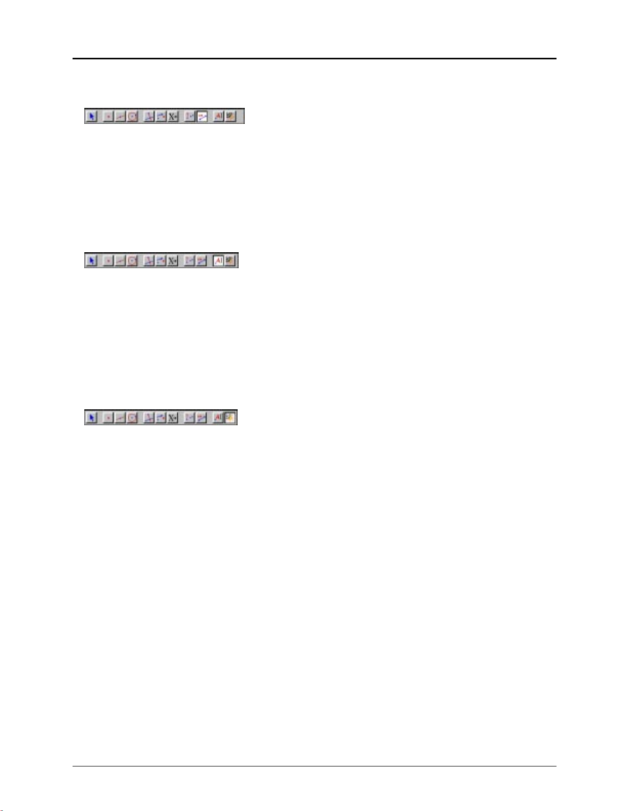
Table of Contents
(continued)
CHAPTER 11: USING THE MEASURE TOOLBOX
Distance & Length
..................................................................................
Area
.................................................................................
Slope
.................................................................................
Angle
Equation & Coordinates
Calculate
Tabulate
..............................................................................
..............................................................................
......................................................................
.................................................................
CHAPTER 12: USING THE DISPLAY TOOLBOX
.................................................................................
Label
Comments
Numerical Edit
Mark Angle
Fix/Free
Trace On/Off
Animation
Multiple Animation
.............................................................................
.........................................................................
............................................................................
...............................................................................
...........................................................................
.............................................................................
.....................................................................
.................................
...................................
11–1
11–2
11–3
11–4
11–5
11–6
11–7
11–11
12–1
12–2
12–3
12–5
12–7
12–8
12–9
12–10
12–11
CHAPTER 13: USING THE DRAW TOOLBOX
Hide/Show
Color
...................................................................................
Fill
Thick
Dotted
Modify Appearance
Show/Hide Axes
New Axes
Define Grid
INDEX
.............................................................................
............................................................................
.................................................................................
.................................................................................
................................................................................
.....................................................................
.......................................................................
.............................................................................
.....................................................................................................
......................................
INDEX–1
13–1
13–2
13–3
13–4
13–5
13–6
13–7
13–8
13–9
13–10
Copying permitted provided TI copyright notice is included
© 1997, 1999 Texas Instruments Incorporated
v
Page 8

About this Guidebook
The Cabri Geometry II Guidebook contains user information about the Cabri Geometry II
software. It provides descriptions, procedures, illustrations, and examples for using the software
features on Macintosh computers, and Windowsé and MS-DOSë-based PCs.
4 Many of the procedures, illustrations, and examples are virtually the same for the different
computer types. Significant differences between the Macintosh, Windows, and DOS versions
are identified for your convenience.
4 Most of the illustrations are from the Macintosh version; several are from the Windows and
DOS versions. Due to space limitations, we could not show every illustration for each version.
Therefore, some illustrations in this guidebook may be slightly different on your computer.
4 Key names are shown in small capital letters such as
Escape key. The
the same function. In this guidebook, “Press
Structure
The Cabri Geometry II Guidebook contains the following chapters and appendices:
4 Chapter 1 describes the basic operations for using Cabri II, starting with checking system
requirements for installing the software, through constructing objects, to saving and printing a
construction file.
4 Chapter 2 describes the Cabri II menus and provides step-by-step procedures for using them.
4 Chapters 3 through 13 describe the Cabri II tools and provide step-by-step procedures for
using them. Each chapter discusses a specific group of Cabri II tools.
Definitions
The following definitions will help you in your understanding of this guidebook.
point When used as an instruction, point means to place the screen pointer on
click Click means to press and release the mouse button quickly, usually when
double-click Double-click means to click the mouse button twice in succession.
RETURN
key on the Macintosh and the
ENTER
top of the object you wish to select.
pointing to a specific location
CTRL
for the Control key and
ENTER
key on the PC keyboard perform
” means to press either
ENTER
ESC
or
for the
RETURN
.
vi
drag Drag means to point to the object you want to drag, press and hold the
mouse button to select the object, and move the screen pointer to a new
location. Release the mouse button to stop dragging.
modify When used as an instruction, modify means to change the appearance,
size, location, or orientation of the object.
marquee outline Marquee outline is the outline of an object in animated dots, similar to a
movie marquee.
marquee rectangle Marquee rectangle is the selection rectangle that appears when you drag
Pointer
with the
tool from an unoccupied location in the drawing window.
When you release the mouse button, objects that lie completely within
the rectangle are selected.
Copying permitted provided TI copyright notice is included
© 1997, 1999 Texas Instruments Incorporated
Page 9

Chapter 1: Learning the Basics
This chapter provides descriptions and examples of basic operations in Cabri Geometry II.
Becoming familiar with these items will enhance your usage. Differences between the Macintosh,
Windows, and MS-DOS versions are explicitly described where applicable. For convenience, DOS
will be used in the remainder of this guidebook to mean MS-DOS.
The following topics are discussed:
FIRST STEPS CONSTRUCTING OBJECTS
Checking system requirements
Installing Cabri Geometry II
Starting Cabri Geometry II
Optimizing your Macintosh system
configuration
Changing your Macintosh system
configuration using Cabri Geometry II
Using Cabri Geometry II on a network
The Cabri Geometry II window
Accessing on-line help
About menus and toolboxes
Pointers that guide you
Creating and selecting points
Handling ambiguities
Determining dependent and independent
objects
Dragging
Using the Undo/Redo command
Deleting objects
Changing the appearance of objects
Labeling objects
Scrolling the drawing window
Saving and printing
Copying permitted provided TI copyright notice is included
© 1997, 1999 Texas Instruments Incorporated
Chapter 1: Learning the Basics 1-1
Page 10

First Steps
Checking system requirements
Macintosh DOS
¦ Macintosh Classic or better.
¦ System 6.0 or later.
¦ 1 Mb available RAM for a Macintosh
Classic. (Memory requirements will be
greater for color or larger monitors than on
the Classic.)
¦ Hard disk with 1.2 Mb available for
program and demonstration files.
Windows 3.1 Windows 95
¦ 386 PC or better required; 486DX
recommended.
¦ PC must be in 386-Enhanced mode with
Virtual Memory enabled.
¦ VGA, SVGA video adapter and a color
monitor.
¦ 6 Mb RAM (minimum) memory installed.
¦ 7 Mb available hard disk space for program,
demonstration files, and system extensions.
¦ Mouse, or an equivalent pointing device.
¦ DOS-compatible computers (PCs), 386 or
better, and running MS-DOS 3.3 or later.
¦ EGA, VGA, SVGA video adapter and a color
monitor.
¦ 3 Mb RAM (minimum) memory installed.
¦ Hard disk with 2.5 Mb available for
program and demonstration files.
¦ Mouse, or an equivalent pointing device.
¦ 386 PC or better required; 486DX
recommended.
¦ VGA, SVGA video adapter and a color
monitor.
¦ 6 Mb RAM (minimum) memory installed.
¦ 2 Mb available hard disk space for program
and demonstration files.
¦ Mouse, or an equivalent pointing device.
Installing Cabri Geometry II
Macintosh DOS
1. Create a folder named
disk.
2. Insert the Cabri Geometry II Macintosh
diskette in your floppy disk drive.
3. Double-click on the
and follow the directions on the screen.
Windows 3.1 Windows 95
1. Insert the Cabri Geometry II for Windows
diskette #1 in your floppy disk drive.
2. From Program Manager, click on
A:\SETUP
enter
prompts.
, and then follow the screen
Cabri II
Installer
on your hard
on the diskette
RUN
and
1. Insert the Cabri Geometry II DOS diskette
in your floppy disk drive.
2. At the DOS prompt, enter:
A:\INSTALL
follow the screen prompts.
1. Insert the Cabri Geometry II for Windows
diskette #1 in your floppy disk drive.
2. Click on
and then follow the screen prompts.
START/RUN
B:\INSTALL
or
and enter
, and then
A:\SETUP
,
Installing Cabri Geometry II on a network
If you have purchased the network license for Cabri Geometry II, you may run the software on
your network. Use network procedures that are compatible with your network to install Cabri
Geometry II. See your Macintosh, Windows, or DOS User’s manual or your network
documentation for more information, if necessary.
Note: Cabri Geometry II is supplied on high-density diskettes. If your computer will not accept
these diskettes, call, 1-800-TI-CARES and a service representative will supply you with low density
diskettes.
1-2 Chapter 1: Learning the Basics
Copying permitted provided TI copyright notice is included
© 1997, 1999 Texas Instruments Incorporated
Page 11

Installing Cabri Geometry II on a network
(continued)
Macintosh and DOS
1. Install Cabri Geometry II on the network server using the instructions given on the previous
page.
2. Run the program from the server the first time, and enter the requested information.
3. To run Cabri Geometry II on each network client, go to the directory on the network server
where the Cabri Geometry II application is installed. Macintosh users may double-click on
the Cabri II icon; DOS users may run Cabri2.exe to start the program.
The procedure described below, for Windows users, allows multiple client computers to run Cabri
Geometry II using the application software installed on the network server. Each client computer
is provided with the necessary system files to run Cabri Geometry II and a shortcut icon that is
linked to the application file on the network server.
Windows 3.1 and Windows 95
1. Install Cabri Geometry II on the network server using the instructions given on the previous
page. In the
Select Destination
screen, you must select a directory that will be accessible from each
client computer on the network.
2. Temporarily copy
setup.exe
and
setup.w02
from the installation diskettes to the same directory in
which you installed Cabri Geometry II in step 1.
3. On each network client, go to the directory on the network server that contains
setup.exe
and
double-click to on this file to run the setup program.
4. In the
Select Destination Directory
screen, click on the
Browse
button and select the same directory
that you used in step 1. Make sure the correct directory is displayed at the top of the window.
OK
You may edit the path, if necessary, and then click on
. Ignore the message that the directory
already exists.
5. In the
Select Components
screen, deselect the first three components. The installation program
will determine if the fourth component is necessary for Windows 3.1x users.
6. When Cabri Geometry II has been installed on all client computers, delete the two files that
were temporarily copied to the network server in step 2.
Starting Cabri Geometry II
Macintosh DOS
You can use one of four methods to start the
software on a Macintosh:
¦ Use
Open
¦ Double-click on the
¦ Double-click on any Cabri Geometry II
construction file, tool configuration file, or
macro file.
¦ Drag and drop any construction file onto
Cabri II
the
Windows
Double-click on the
Copying permitted provided TI copyright notice is included
© 1997, 1999 Texas Instruments Incorporated
Finder
in the
.
Cabri II
icon.
icon (System 7 users only).
Cabri II
icon.
Type
CABRI
and press
ENTER
from the DOS
prompt directory where the Cabri Geometry II
files are located.
(Optional) Add the Cabri directory to your DOS
path to open Cabri Geometry II from any
directory.
Chapter 1: Learning the Basics 1-3
Page 12
First Steps
(Continued)
Optimizing your Macintosh system configuration
If you are starting Cabri Geometry II on a Macintosh for the first time, you may need to make some
adjustments to make Cabri Geometry II compatible with your Macintosh computer system
configuration.
Graphics intensive programs require a large amount of memory to operate. The amount of memory
required directly relates to the size of your monitor and to the number of colors chosen to
represent graphical elements. Cabri Geometry II may require more memory than other applications
due to its interactive nature. Cabri Geometry II can assist you in optimizing your system.
If you see a warning message from the
configuration. This message indicates the amount of memory needed to run Cabri Geometry II
efficiently on your computer with your current configuration.
Click the
windows that are currently open. This frees the memory that these applications are using.
To change the amount of memory allocated to Cabri Geometry II, first make sure the
selected. Then, from the
decrease the application memory size to a value that is compatible with your computer.
Finder
, you need to make some adjustments to your system
OK
button to proceed (Cabri Geometry II does not start). Then close any applications or
Cabri II
Finder
, select
Get Info
in the
File
menu. Once the
Get Info
window appears,
icon is
If you are using System 7, an optional method is to use
Virtual Memory
to increase the amount of
memory available to applications. See your Macintosh User’s manual for more information.
The previous dialog box indicates the amount of available memory on your computer. You may
also select
About this Macintosh
in the
Apple
menu for the same information.
Changing your Macintosh system configuration using Cabri II
If you open Cabri Geometry II and the memory allocation on your Macintosh is not optimal, the
following dialog box appears. We recommend that you allow Cabri Geometry II to select optimal
Manual
parameters for your system automatically or that you select them using the
You may wish to quit and modify the settings yourself if you are familiar with the memory and
monitor control panels.
If you select the
Automatic
button, Cabri Geometry II computes the optimal settings for your
computer and then quits. The number of colors may change in the process of optimizing your
configuration. Double-click on the Cabri Geometry II icon for the changes to be applied to Cabri
Geometry II.
button.
Manual
If you select the
button, Cabri Geometry II continues to the optimization dialog box (see
example on the next page) that allows you to optimize your configuration as you want. Read the
items in the
Current Settings
field first, and then manipulate the other fields as described below the
example. (You can also access the following dialog box by pressing the
the software.)
1-4 Chapter 1: Learning the Basics
OPTION
Copying permitted provided TI copyright notice is included
© 1997, 1999 Texas Instruments Incorporated
key when starting
Page 13
Status:
The status indicates whether or not Cabri Geometry II can run with the
current settings.
# Screen Colors
Memory Setting
# Objects
# Colors
The number of colors used to display objects is directly related to the
amount of memory required to execute Cabri Geometry II. You can click
on the up or down arrow buttons in this field to change the number of
Status
screen colors. Check the
acceptable. Click on
OK
to continue.
field to determine if these values are
The amount of memory available and the number of colors displayed
determine the number of objects that can be constructed. You can click on
the up and down arrow buttons in this field to change the amount of
memory allocated to Cabri Geometry II. The value on the left indicates the
amount of memory required to run Cabri Geometry II on your computer in
black and white. The value on the right indicates the amount of memory
Status
currently available on your computer. Check the
OK
these values are acceptable. Click on
to continue.
field to determine if
The amount of memory available is directly related to the number of
objects that can be constructed. Click on this button to optimize the
number of objects that can be constructed. If memory is limited, Cabri
Geometry II will probably suggest that fewer colors be used to construct
more objects. For optimal performance, Cabri Geometry II attempts to
allocate enough memory to construct at least 300 objects.
The number of colors used to display objects is directly related to the
amount of memory required to execute Cabri Geometry II. Click on this
button to optimize the number of colors displayed. If you use other
applications regularly that require 256 colors, you may wish to optimize
the number of colors. Given limited memory, this decreases the number of
objects that you can construct.
Copying permitted provided TI copyright notice is included
© 1997, 1999 Texas Instruments Incorporated
Chapter 1: Learning the Basics 1-5
Page 14
First Steps
(Continued)
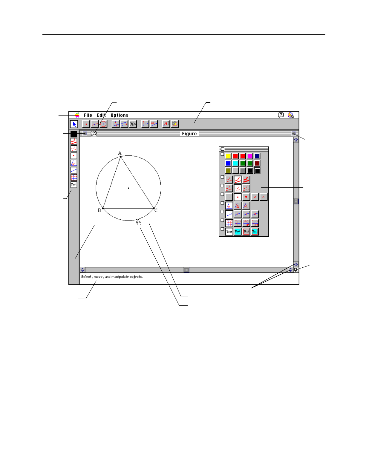
The Cabri Geometry II window
The illustration below shows the Cabri Geometry II window. This window contains the essential
elements of the Cabri Geometry II software. A description of each element follows the illustration.
Note: The screen shown below illustrates the Macintosh version. Screens on Windows and DOS
systems are similar but slightly different.
Menu
Bar
Close
Box
Attribute
Icons
Drawing
Window
Help Icon
Toolbar
Zoom
Box
Attribute
Palette
This circle
Size
Box
Help Window
Elements of the Cabri Geometry II window
Drawing Window
Menu bar
1-6 Chapter 1: Learning the Basics
This region is where you build geometric constructions.
The menu bar contains common graphic user interface menus for file
management and editing, together with Cabri Geometry II options.
Scroll Bars
Pointer Message
Selection Pointer
Copying permitted provided TI copyright notice is included
© 1997, 1999 Texas Instruments Incorporated
Page 15
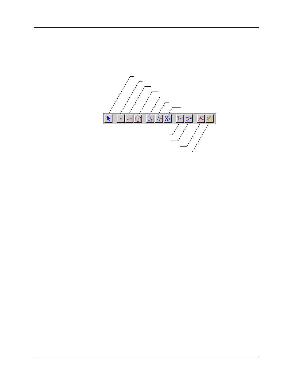
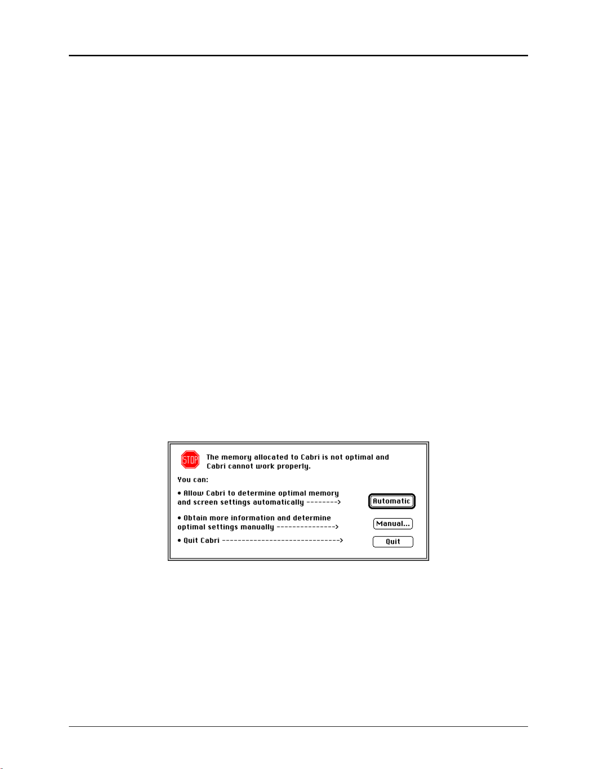
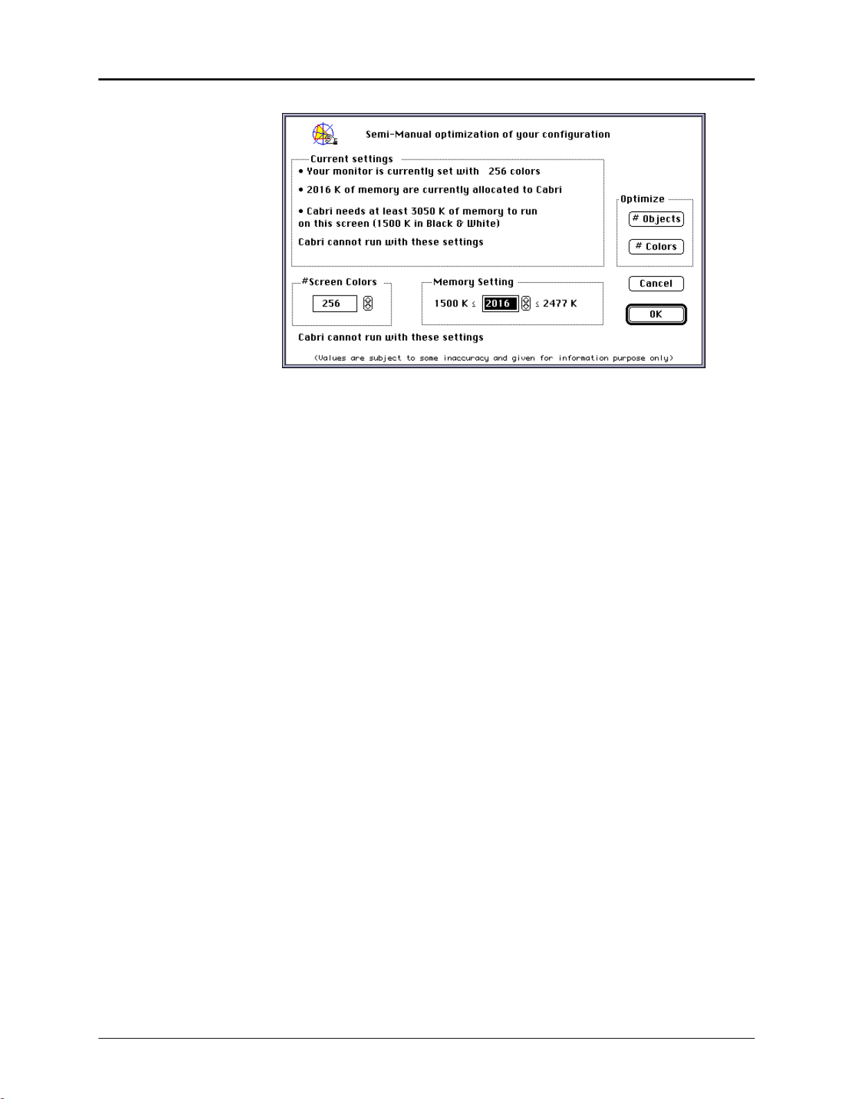
Toolbar
y
y
The toolbar contains tools for building constructions. Eleven toolboxes
reside on the toolbar (see illustration below). To access a toolbox, press
and hold the mouse button on the icon. The items in that toolbox
appear.
Pointer
Points
Lines
Curves
Construct
Transform
Macro
Check Propert
Measure
Displa
Draw
Attribute icons
Help Icon
A
(Macintosh)
Help menu option
(Windows, DOS)
Selection pointer
Close box
Zoom box
(Macintosh, Windows)
Size box
(Macintosh, Windows)
Scroll bars
(Macintosh, Windows)
The attribute icons are not displayed unless you select the
command in the
Options
menu on the menu bar. These allow you to
Show Attributes
modify the appearance of objects. You can create an attribute palette
(tear-off menu) by dragging an icon from the attribute icons to the
drawing window.
Clicking on the help icon A creates a help window at the bottom of your
screen that contains useful help messages for each command. Clicking
on the A again removes the help window.
Clicking on the
Help
menu option and selecting
key toggles the help window ON and
OFF
Help
or pressing the
F1
.
The selection pointer is the primary tool for selecting menus and
building constructions. The shape of the pointer changes according to its
current operation and location.
The close box closes the window and creates a dialog box that allows
you to save your work if you have not done so.
The zoom box toggles the size of the window between the current size
and the full screen size.
Dragging the size box to a new location resizes the drawing window.
Clicking in the scroll bars or on the scroll arrows moves the contents of
the drawing window vertically or horizontally.
Copying permitted provided TI copyright notice is included
© 1997, 1999 Texas Instruments Incorporated
Chapter 1: Learning the Basics 1-7
Page 16

First Steps
(Continued)
About menus and toolboxes
Operations are grouped by type in the pull-down menus located on the menu bar and on the
toolbar. Once a tool is selected, it remains active until you select another tool. If the icon of the
tool you want is shown on the toolbar, select it by clicking once on the icon. Commands in the
menu bar must be selected each time they are used.
Descriptions of the Cabri Geometry II menus and toolboxes follow:
MENUS
Apple
(Macintosh only)
File
Edit
Options
Window
(Windows)
Help
(Windows, DOS)
TOOLBOXES Tools for ...
Pointer
Points
Lines
Curves
Construct
Apple menu items or the Cabri Geometry II logo screen.
Commands for opening, closing, saving, or printing constructions.
Commands for selecting or copying objects, refreshing the drawing window,
or replaying constructions.
Commands for tool configurations, hide/show attributes, preferences, or
setting software defaults (Macintosh only).
Standard Windows display options.
Help options.
Selecting or for free-hand transformations.
Constructing points.
Constructing linear objects.
Constructing circles, arcs, or conics.
Euclidean geometry constructions.
Transform
Macro
Check Property
Measure
Display
Draw
1-8 Chapter 1: Learning the Basics
Transformational geometry.
Making macros. New macros become part of this toolbox.
Checking properties of constructions based on Euclidean geometry.
Measurements or calculations.
Annotating your constructions or animating objects.
Changing the appearance of objects or displaying the coordinate system.
Copying permitted provided TI copyright notice is included
© 1997, 1999 Texas Instruments Incorporated
Page 17

Accessing on-line help
Macintosh DOS
¦ Access on-line help by clicking on the help
icon A in the menu bar of the Cabri
Geometry II drawing window.
¦ A window appears at the bottom of your
drawing that contains information about
the tool currently selected.
¦ Select additional tools to see their help
information.
¦ Remove the help window by clicking on
the help icon again or by clicking on the
close box in the help window.
¦ The close box appears when you click in
the help window.
Windows
¦ Access on-line help by clicking on the
Help menu option in the menu bar of the
Cabri Geometry II drawing window and
Help
selecting
.
¦ A window appears at the bottom of your
drawing that contains information about
the tool currently selected.
¦ Access on-line help by clicking on the
Help menu option in the menu bar of the
Cabri Geometry II drawing window and
selecting
Help
, or press F1.
¦ A window appears at the bottom of your
drawing that contains information about
the tool currently selected.
¦ Select additional tools to see their help
information.
¦ Remove the help window by clicking on
the help icon again or by pressing
F1
.
¦ Select additional tools to see their help
information.
¦ Remove the help window by clicking on
the help icon again.
Copying permitted provided TI copyright notice is included
© 1997, 1999 Texas Instruments Incorporated
Chapter 1: Learning the Basics 1-9
Page 18

Constructing Objects
2
Pointers that guide you
Several types of pointers exist to help guide you through your constructions. The pointers are
illustrated below.
Pointer Cursor looks like...
arrow
cross hair
construction pencil
selection pencil
pointing hand
selection hand
dragging hand
open hand
grasping hand
magnifying glass
I-beam
paint brush
!
$
&
%
(
)
*
"
#
'
I
The pointer is in the toolbar, menu bar, or
scroll bars.
Pointer
The
A construction tool is active.
A construction tool is active and a point can
be placed on an object.
A point can be selected.
An object is dependent or to show the
intermediate stage between selecting an
object and dragging.
An object can be moved.
The
(DOS) is pressed.
The window can be scrolled using the
mouse.
An ambiguity exists.
Text or numbers can be entered or edited.
Color or attributes can be changed.
tool is active.
COMMAND
key (Macintosh) or the
CTRL
paint bucket
crossed lines
column width
1
4
3
An object can be filled with a pattern or
color.
Comment
The
The column width of the table can be
adjusted.
option is active.
Creating and selecting point*s
All objects are constructed using one or more points. You create or select points when a tool is
active. In general, the order of operation is to select a construction tool from the toolbox, and then
to create or select the required points that define the tool.
A point is created by a single click of the mouse. You can create points in unoccupied space when
construction pencil
the
two objects when a cursor message appears and the pointer changes to the
The following examples illustrate how to create and select points.
# cursor is visible. You can create a point on an object or at the intersection of
selection pencil
' cursor.
1-10 Chapter 1: Learning the Basics
Copying permitted provided TI copyright notice is included
© 1997, 1999 Texas Instruments Incorporated
Page 19
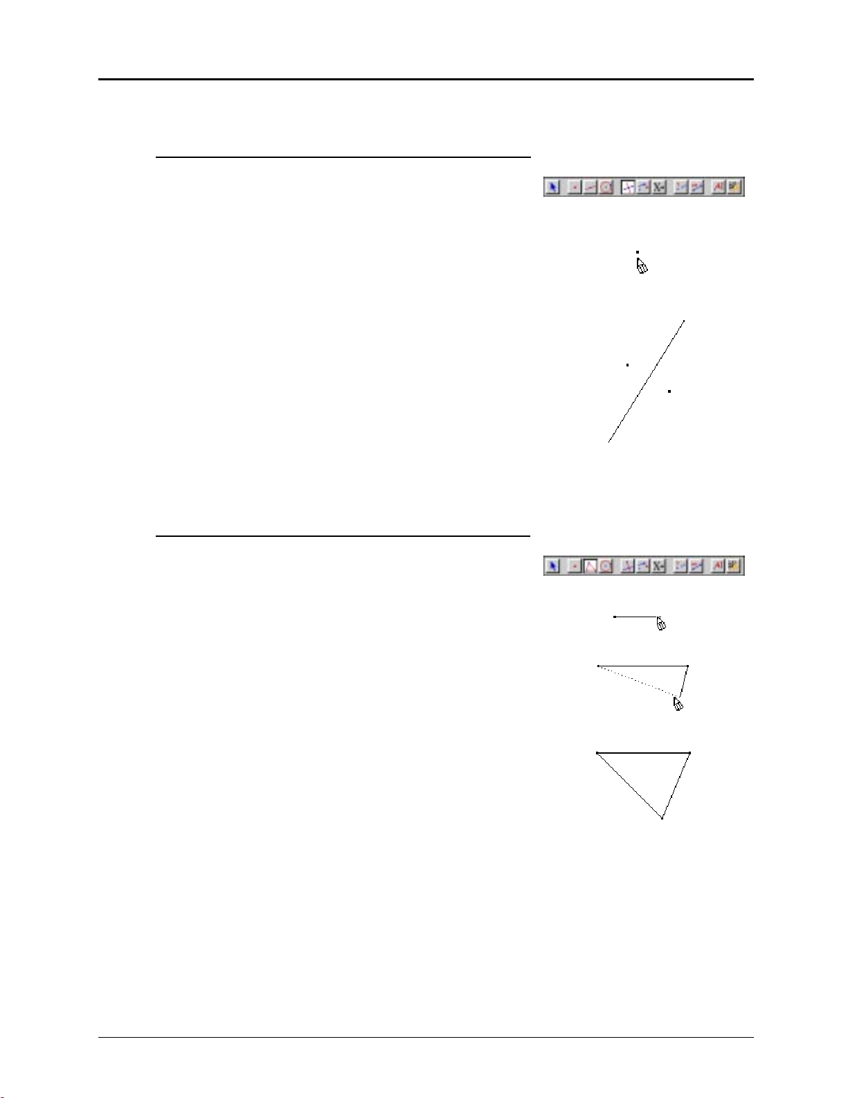
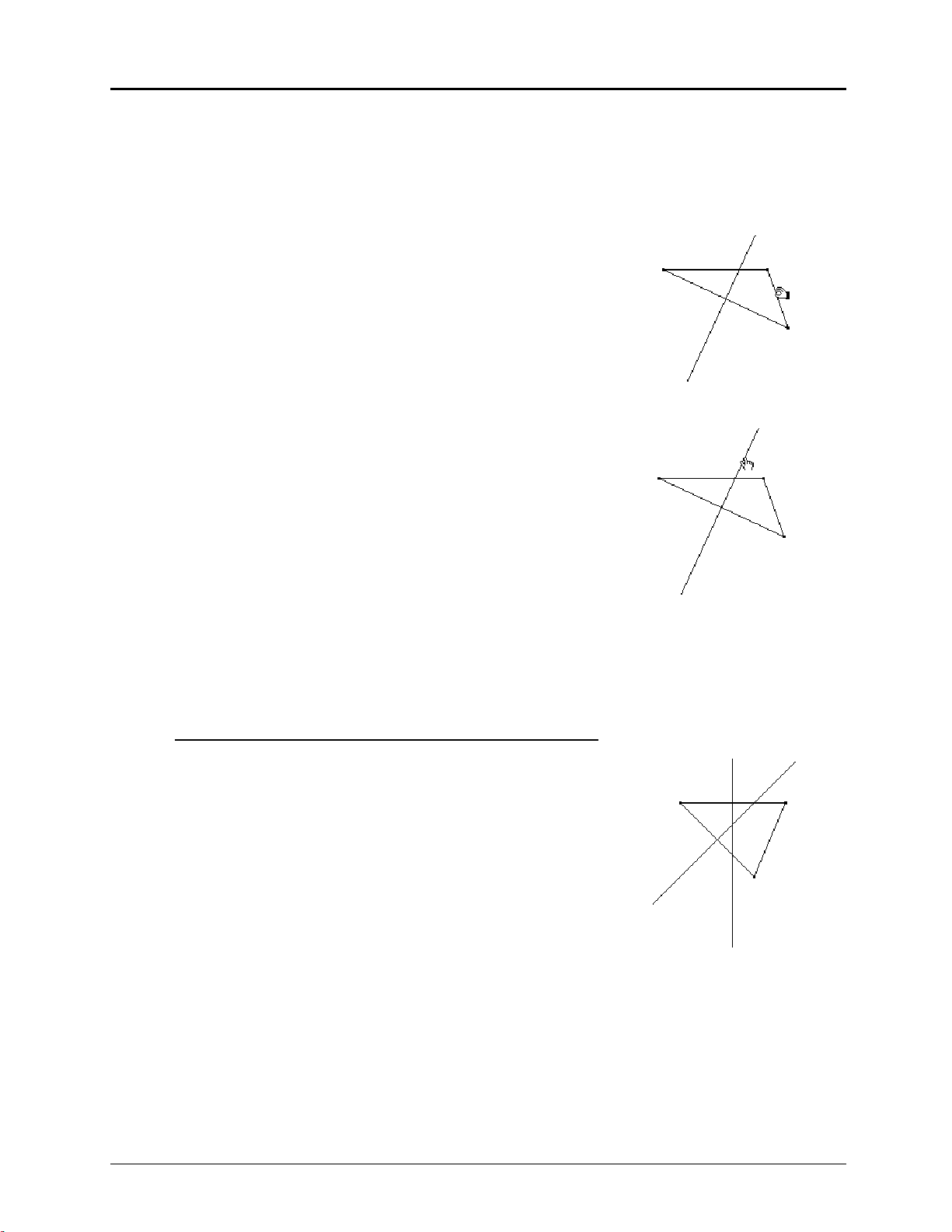
Example 1: Creating the perpendicular bisector of two
points
1. Select the
Perpendicular Bisector
tool from the
Construct
toolbox.
2. Move the # to any place in the drawing window and click
(not hold down) once.
A flashing point appears on the window, indicating that
this point has been selected for the construction.
3. Move to another place and click again.
A second point appears as well as the perpendicular
bisector of the segment connecting these two points.
(Note: The segment does not appear.)
If the pointer is near a valid object, a cursor message is
displayed. In some cases, it is sufficient to select only
one object to define a construction, as the next example
demonstrates.
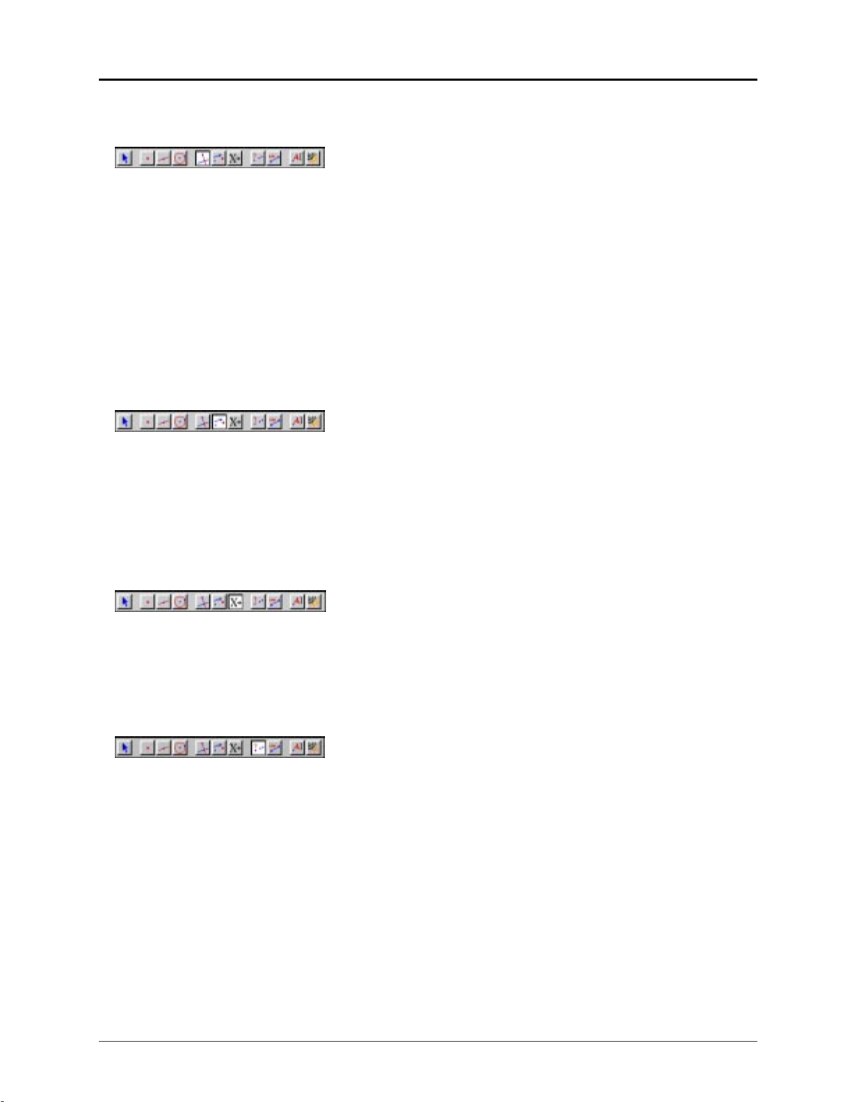
Example 2: Creating the perpendicular bisector of a side of
a triangle
1. Select
Triangle
from the
Lines
toolbox.
2. Move the # to any place in the drawing window and
click. Move to a second location and click, and then to a
third location and click.
A triangle appears in the drawing window with the three
points selected as vertices.
Note: Depending on the speed at which you constructed
these three points, the sides of the triangle might appear
during the construction. Try doing this slowly and watch
the triangle materialize.
3. Select
Perpendicular Bisector
from the
Construct
toolbox.
Copying permitted provided TI copyright notice is included
© 1997, 1999 Texas Instruments Incorporated
Chapter 1: Learning the Basics 1-11
Page 20
Constructing Objects
(Continued)
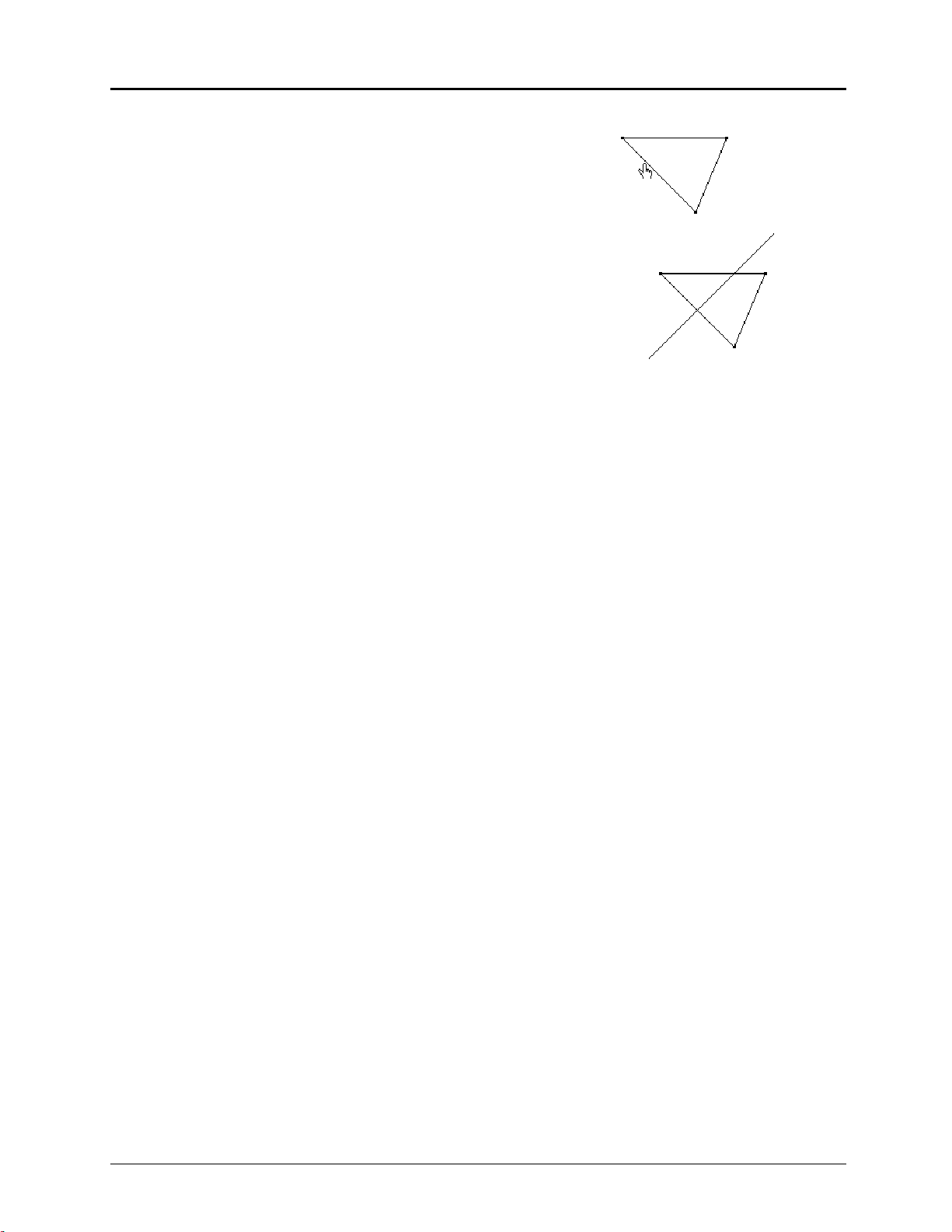
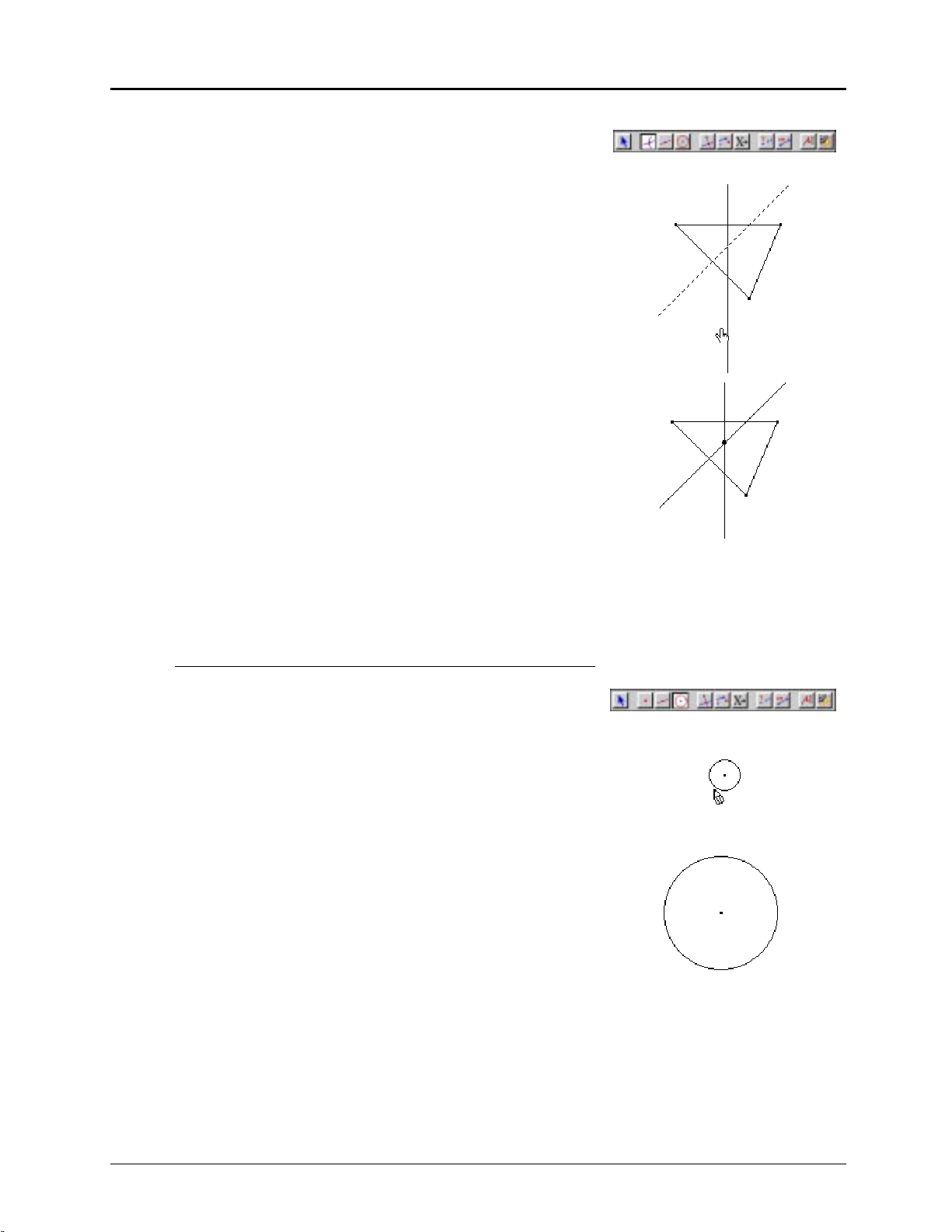
4. Move the cursor as follows so that the message
Perpendicular bisector of this side of the triangle
When the cursor is in unoccupied space in the drawing
window, the # appears. Move the cursor near a side of
the triangle. The cursor changes from the # to the $ with
the message
Perpendicular bisector of this side of the triangle
(If the cursor is near a vertex of the triangle, the cursor
message
This point
appears.)
Click once, and the perpendicular bisector of the side of
the triangle appears.
Handling ambiguities
appears.
Perpendicular bisector of this side of the triangle
.
When two or more objects simultaneously occur at the location of the pointer, the
* cursor and the cursor message
Which object?
appear. Press and hold down the mouse to see the
magnifying glass
options in a dialog box. Select an object by pointing to the appropriate choice in the box and
releasing the mouse.
When multiple objects are present, they are listed in the order in which they were created.
Selecting an object causes it to display in marquee outline. You can move (drag) it to a new
Pointer
location if it is an independent object and the
tool is selected. Click in unoccupied space to
deselect the object. If you are using a construction tool, the object is selected for the construction.
Determining dependent and independent objects
All objects are created using one or more points. The manner in which you create an object
determines whether it is dependent or independent of the object. This distinction becomes very
important with respect to dragging objects. An example of this distinction is given after the section
“Dragging.”
A point constructed by itself is called a basic point.
An independent object is an object created using only basic points. Independent objects can be
moved (dragged) but not modified directly. By moving the basic points used for their construction,
you can modify them indirectly.
A dependent object is an object constructed using an independent object (or another dependent
object). Dependent objects cannot be moved (dragged) or modified directly. You can move or
modify them indirectly by moving the basic points or independent objects responsible for their
existence.
The more elaborate a construction becomes, the more difficult it can be sometimes to distinguish
these types. However, the Cabri Geometry II software will assist you.
1-12 Chapter 1: Learning the Basics
Copying permitted provided TI copyright notice is included
© 1997, 1999 Texas Instruments Incorporated
Page 21
Dragging
Dragging objects is valuable for generating conjectures. You can modify an object by dragging all
or part of it to a new location. Whether or not an object can be changed depends directly on how it
was created.
You can drag (move) a basic point to a new location, modifying, in turn, any object constructed
Pointer
using it. An independent object can be modified with one of the tools from the
cannot alter a dependent object directly by dragging, but you can change it by dragging the basic
points used in its construction.
toolbox. You
Whenever an object can be dragged, the pointer changes to the
then to the
dragging hand
% cursor. When the % is visible, the selected object follows the pointer as
selection hand
& momentarily and
you move it.
If your computer's performance is sluggish, you may need to move the pointer to the location you
want and wait for the computations to finish with the new characteristics. This is particularly
evident when there are many objects in the drawing window.
If the object is dependent (cannot be dragged), the pointer changes to the
reverts to the
cross hair
! cursor.
selection hand
& and then
Example 3: Evaluating basic points, independent objects,
and dependent objects
1. Construct the perpendicular bisector of a side of a
triangle (see Example 2).
(The vertices are basic points, the triangle is an
independent object, and the perpendicular bisector is a
dependent object.)
2. Basic points:
Pointer
Select
from the
Pointer
toolbox.
Move the ! near a vertex of the triangle (the cursor
changes to the $ with the message
Press and hold down the mouse button.
The cursor changes to the & and then almost
immediately to the %.
When you drag the point, the triangle changes its size
and shape, and the perpendicular bisector changes
accordingly.
These results are characteristics of using a basic point.
An inquiry that could be made here is: “When does the
perpendicular bisector of one side of a triangle contain
a vertex of the triangle?”
Copying permitted provided TI copyright notice is included
© 1997, 1999 Texas Instruments Incorporated
This point
).
This point
Chapter 1: Learning the Basics 1-13
Page 22
Constructing Objects
(Continued)
3. Independent objects:
Move the ! near a side of the triangle (the cursor
changes to the $ with the message
Press and hold down the mouse button.
The cursor changes to the & and then almost
immediately to the %.
Continue to hold down the mouse and move the triangle
about the drawing window.
The triangle does not change its size or its shape, while
the perpendicular bisector moves along with the triangle.
The triangle was constructed using three basic points as
its vertices; therefore, it is an independent object and
can be moved.
4. Dependent objects:
Move the ! near the perpendicular bisector (the cursor
changes to the $ with the message
Press and hold down the mouse button.
This triangle
This line
).
).
This line
The cursor changes to the & and then almost
immediately back to the !.
The perpendicular bisector cannot be modified directly;
it is a dependent object.
Note: You can modify the perpendicular bisector
indirectly by dragging the basic points or the
independent objects used for its creation.
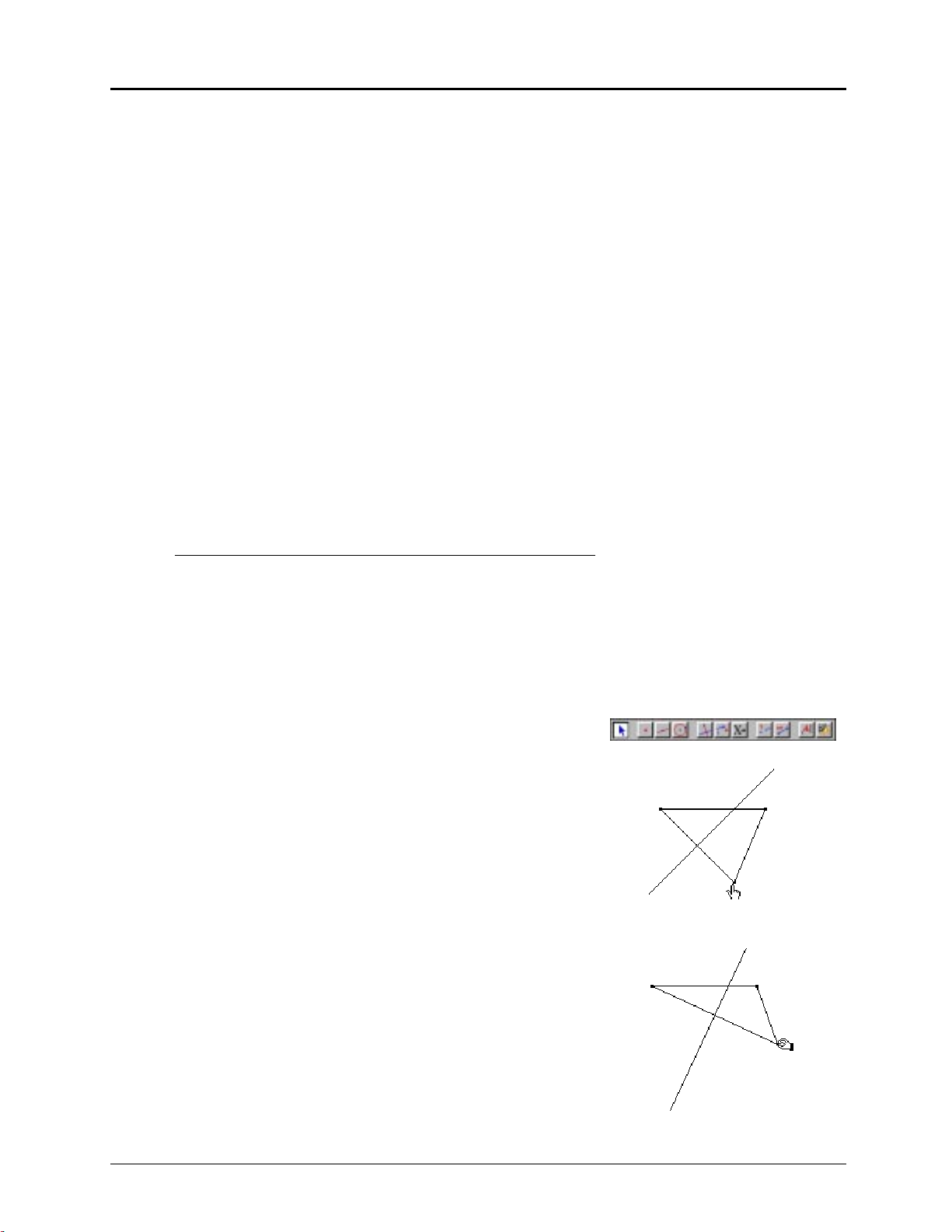
Example 4: Creating the circumcenter of a triangle
1. Construct the perpendicular bisector of one side of a
triangle (see Example 2.)
2. Construct the perpendicular bisector of a second side.
1-14 Chapter 1: Learning the Basics
Copying permitted provided TI copyright notice is included
© 1997, 1999 Texas Instruments Incorporated
Page 23
3. Choose
Intersection Point(s)
from the
Points
toolbox.
4. Point to one of the perpendicular bisectors (the cursor
message
This line
appears) and click once.
The line changes to marquee outline.
5. Point to the other perpendicular bisector. After the
cursor message appears, click once.
The first line returns to solid, and a point at the
intersection of the two lines appears. This point of
This line
intersection is known as the circumcenter of the triangle.
The vertices of the triangle are basic points. The triangle
is an independent object because its existence depends
only upon basic points. The perpendicular bisectors are
dependent objects because their existence depends upon
independent objects (the sides of the triangle). The
circumcenter is a dependent object because it was
created using dependent objects (the perpendicular
bisectors).
In Example 5, we will first create a circle, and then inscribe a triangle. You can move the circle by
dragging its center point or modify it by dragging its circumference. The triangle cannot be moved.
However, you can modify it by dragging any one of its vertices around the circle.
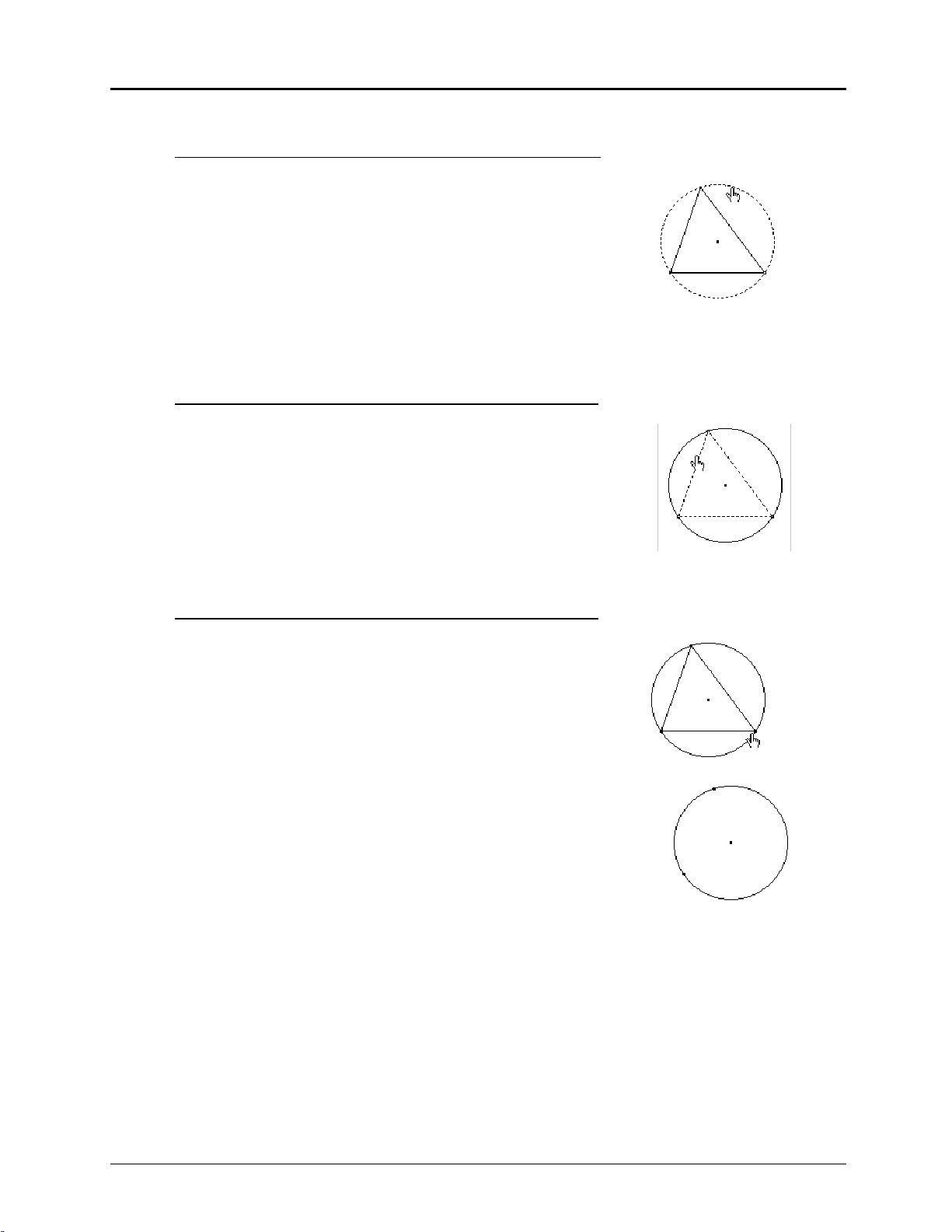
Example 5: Inscribing a triangle in a circle
1. Choose
Circle
from the
Curves
toolbox.
2. Move the # to any place in the drawing window and click
once.
A flashing point appears.
3. Move the cursor away from the flashing point.
A circle appears with the flashing point as its center.
Click again to finish constructing the circle.
Note: The flashing point changes to solid to indicate the
construction is completed.
Copying permitted provided TI copyright notice is included
© 1997, 1999 Texas Instruments Incorporated
Chapter 1: Learning the Basics 1-15
Page 24
Constructing Objects
(Continued)
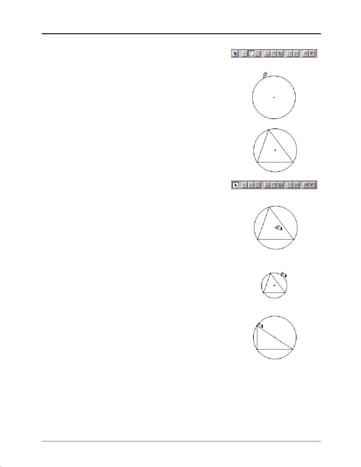
4. Choose
Triangle
from the
Lines
toolbox.
5. Move the # to any point of the circle (the cursor message
On this circle
appears), and click once.
6. Move the cursor to a second and third point on the
circle, clicking once at each point.
A triangle becomes inscribed in the circle.
7. Choose
Pointer
from the
Pointer
toolbox.
8. Move the ! cursor near the center point (the cursor
message
This point
appears).
Press and hold down the mouse button until the %
appears, and drag the center point around the drawing
window.
On this circle
Note: The radius of the circle remains unchanged.
9. Move the ! near the circumference of the circle (the
cursor message
This circle
appears).
Press and hold down the mouse button until the %
appears, and drag the circumference.
Note: The center point of the circle remains fixed while
the radius changes, and the vertices of the triangle stay
on the circle.
10. Move the ! near a vertex of the inscribed triangle (the
cursor message
This point
appears).
Press and hold down the mouse button until the %
appears, and then drag the point.
Note: The point can only be moved along the circle.
If you move the pointer while creating points, Cabri Geometry II reverts to dragging. This feature
anticipates your intent to modify your construction without requiring you to return to the
Pointer
toolbox. However, it can create some confusion if you are creating points quickly and
inadvertently move the pointer while pressing the mouse. In this case, a point will not be created.
1-16 Chapter 1: Learning the Basics
Copying permitted provided TI copyright notice is included
© 1997, 1999 Texas Instruments Incorporated
Page 25
Using the Undo/Redo command
You can cancel an operation that has just been completed by using the
Edit
menu. Only the most recent operation can be undone.
To review additional steps in your construction, see the
Replay Construction
Undo/Redo
command in the
command in the
Edit
menu. This command allows you to replay each step of a construction.
Deleting objects
Delete objects by selecting them, and then pressing
Edit
menu.
DELETE
or selecting the
Select multiple objects by pressing the mouse in free space and dragging a marquee rectangle
around the objects to be deleted. Only objects that are fully enclosed by the marquee rectangle will
be deleted. All selected objects are displayed in marquee outline.
Select all objects in the drawing window by using the
press
DELETE
pressing
pressing
or select
COMMAND+A
DELETE
.
Clear
from the
(Macintosh) or
Edit
menu. You can also clear the entire drawing window by
CTRL+A
(Windows, DOS) simultaneously, releasing, then
Select All
command in the
WARNING! When an object is deleted, all objects that depend on that object are deleted as well. It
is possible to delete an entire construction by deleting a single point. If you accidentally delete an
object, you can recover it by using the
Undo/Redo
command in the
Edit
menu.
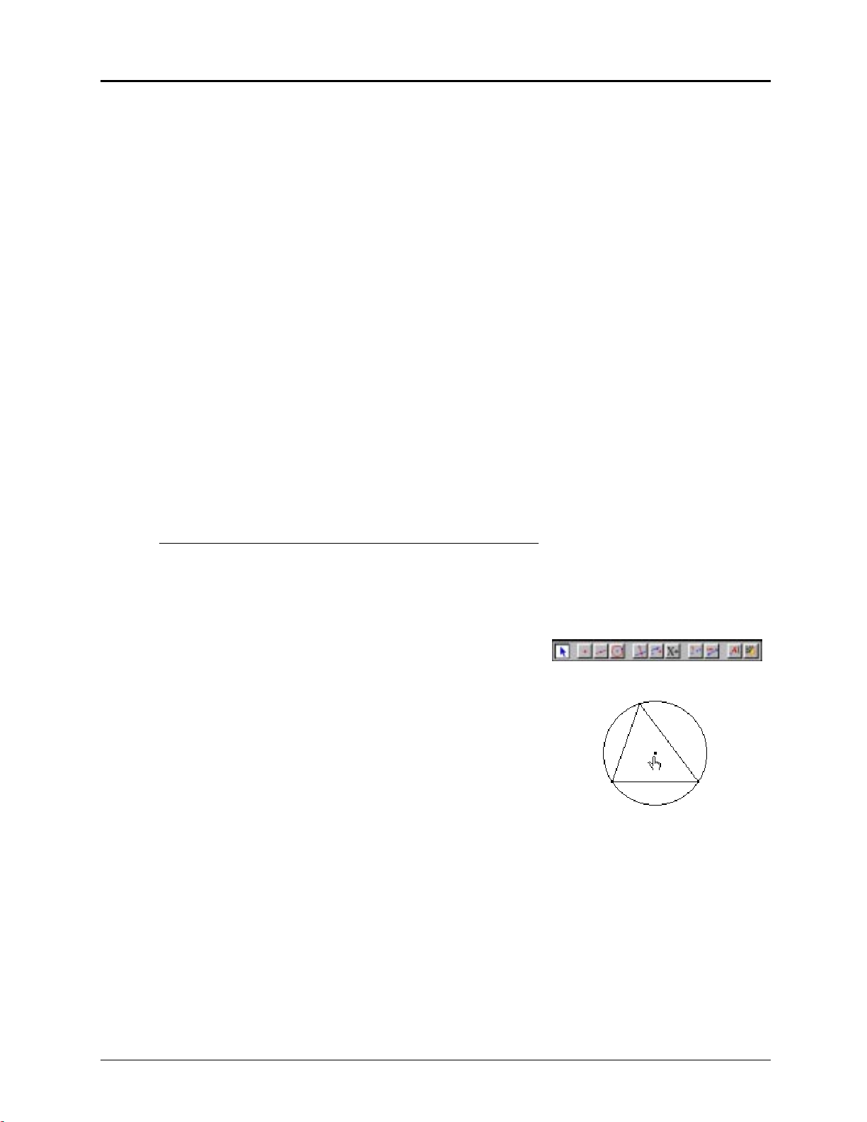
Example 6a: Deleting objects — Method 1
Clear
command in the
Edit
menu. Then
1. Construct a circle and an inscribed triangle
(see Example 5).
2. Select
Pointer
from the
Pointer
toolbox.
3. Point to the center point of the circle and click.
The center point flashes.
Press the
DELETE
key.
The point, the circle, and the triangle disappear.
This point
Copying permitted provided TI copyright notice is included
© 1997, 1999 Texas Instruments Incorporated
Chapter 1: Learning the Basics 1-17
Page 26
Constructing Objects
(Continued)
Example 6b: Deleting objects — Method 2
1. Repeat steps 1 and 2 in Method 1, or select
Edit
the
menu.
Undo/Redo
2. Point to the circle and click.
The circle appears in marquee outline.
Press the
DELETE
key.
The circle and the triangle disappear, but the center point
remains.
Example 6c: Deleting objects — Method 3
1. Repeat steps 1 and 2 in Method 1, or select
Undo/Redo
2. Point to the triangle and click.
Press the
DELETE
key.
The triangle disappears, but the circle, its center point,
and the vertices of the triangle remain.
Example 6d: Deleting objects — Method 4
in
.
This circle
This triangle
1. Repeat steps 1 and 2 in Method 1, or select
Undo/Redo
2. Point to a vertex of the triangle and click.
Press the
DELETE
key.
What happened? How does this differ from Method 3?
.
This point
1-18 Chapter 1: Learning the Basics
Copying permitted provided TI copyright notice is included
© 1997, 1999 Texas Instruments Incorporated
Page 27
Changing the Appearance of Objects
You can change the appearance of objects from the
Access the
Attributes
toolbox, use the
toolbar from the
Fill, Thick, Dotted
To apply attributes from tools in the
modified. To use an option from the
Hide/Show Attributes
Modify Appearance
, or
Draw
menu, select the tool, and then select the object to be
Attributes
toolbar, first select the objects to be modified, and
Attributes
toolbar or the
command in the
tools.
Draw
Options
toolbox.
menu. In the
then select the attribute.
Labeling objects
You can label points in two ways — as you create them or with the
Label
tool in the
Labeling objects as they are created is intended for quick access and is limited to five
alphanumeric characters. Editing is not available at this stage. However, after constructing the
Label
object, you can edit the label with the
tool.
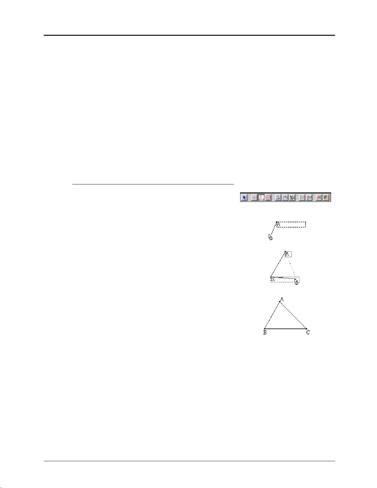
Example 7a: Adding labels during construction
1. Select
Triangle
from the
2. Click on the drawing window. Then type
A point appears with a label
Lines
toolbox.
A
beside it.
A
.
Display
toolbox.
Draw
3. Move the # , click once, and then type
B
.
Another point, a segment connecting the two points,
B
and a label
4. Move the # to a new position, click once, and type
The completed triangle appears as well as the label
appear.
C
.
C
beside the last point created.
The
Label
tool in the
Display
toolbox allows you to attach labels to a point, line, or circle. Once
attached to the object, labels cannot be detached. You can position them near the object using the
Pointer
, and they will retain that position through all modifications to the object.
Copying permitted provided TI copyright notice is included
© 1997, 1999 Texas Instruments Incorporated
Chapter 1: Learning the Basics 1-19
Page 28

Constructing Objects
(Continued)
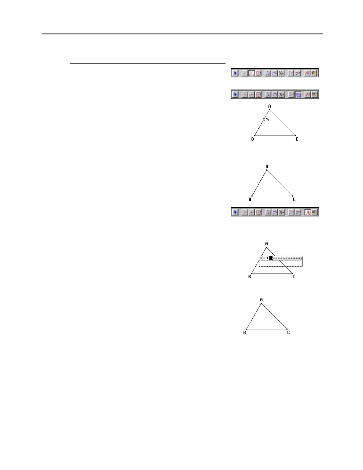
Example 7b: Adding labels after construction
1. Select
Triangle
from the
Lines
toolbox.
2. Construct a triangle on the drawing window.
3. Select
Label
from the
Display
toolbox.
4. Move the ! near a vertex of the triangle.
The cursor changes to the I-beam I (the cursor message
This point
appears).
5. Click once and an edit box appears.
Note: (Macintosh only) On the top row are four options
that generate pull-down menus:
S
for font size, F for font style, and the last box for text
C
for font character set,
color.
This point
6. Type a name for the vertex, and then click anywhere
New York City
outside the edit box.
The box disappears, but the name remains.
7. Repeat for the other vertices.
Los Angeles Miami
You can also apply comments to measurements immediately after creating them. Just begin typing
characters after creating the measurement.
1-20 Chapter 1: Learning the Basics
Copying permitted provided TI copyright notice is included
© 1997, 1999 Texas Instruments Incorporated
Page 29
Example 8: Comments
1. Select
Triangle
from the
2. Construct a triangle and label its vertices
3. Select
Area
from the
Lines
toolbox.
Measure
toolbox.
A, B
, and C.
4. Move the cursor to a side of the triangle until it changes
to the $ (the cursor message
This triangle
appears), and
click once.
Depending on the triangle and the default settings, a
2
number and units label, such as 4.520 cm
5. Begin typing the comment
Area of ABC =
, appears.
.
The comment attaches to the left side of the
measurement.
6. Select
Comments
from the
7. Move the 4 near the area (the cursor message
text
appears and the cursor changes to the I).
Display
toolbox.
Edit this
Click once and an edit box appears with the value of the
area and the comment entered in step 5 on the text line.
This triangle
Area of ABC = 4.520 cm
2
8. Move the cursor between
line, and add the word
The text now reads
“of”
triangle
Area of triangle ABC = 4.520 cm
“
9. Click on the toolbar or press
.
ESC
ABC
“
and
to make the edit box
disappear, leaving the comment on the drawing
window.
”
in the text
Area of ABC = 4.520 cm
2
.”
Area of triangle ABC = 4.520 cm
2
2
Copying permitted provided TI copyright notice is included
© 1997, 1999 Texas Instruments Incorporated
Chapter 1: Learning the Basics 1-21
Page 30

Constructing Objects
(Continued)
Scrolling the drawing window
You can scroll the drawing window within a one-square-meter region by three methods:
4 Use the Show Drawing command in the File menu to view the entire one-square-meter region
in compressed form. You can reposition the active widow, which allows you to work in
another section of the drawing. (Note: When you click and hold the mouse button, the
grasping hand cursor ()) appears.)
4 Use the scroll bars on the right and bottom sides of the drawing window (Macintosh only).
Clicking on the scroll bars or buttons moves the drawing in a horizontal or vertical direction.
4 Press the
left mouse button. The screen scrolls in the direction that you move the pointer.
COMMAND
key (Macintosh) or the
key (Windows, DOS), then press down on the
CTRL
Saving and printing
You can save a construction to a file at any time using the
menu. If the construction has never been saved, these two commands have the same effect.
Save
The
stored. If the construction has already been saved, the
has been modified since the previous save. The new version of the construction replaces the older
one.
The
the older version.
You can print your Cabri Geometry II constructions on a printer. Printed constructions enhance
understanding by providing accurate, printed-to-scale manipulatives. The entire one-square-meter
drawing or a specified portion can be printed in both black and white, or color.
dialog box allows you to name the construction and to choose the folder where it will be
Save as...
command allows you to save the figure to another folder or name without deleting
Save
Save
command is active only if the figure
Save as...
and
commands in the
File
1-22 Chapter 1: Learning the Basics
Copying permitted provided TI copyright notice is included
© 1997, 1999 Texas Instruments Incorporated
Page 31

Chapter 2: Using the Menus
The Cabri Geometry II menus contain standard graphic user interface functions for file
management and editing, plus options for Cabri Geometry II. They are located on the menu bar at
the top of the Cabri Geometry II window.
The following menu options are available. Each option is discussed in this chapter in detail
according to its order on the pull-down menus.
FILE MENU EDIT MENU OPTIONS MENU HELP
New
Open...
1
Close
Save
Save as...
Revert...
4
Show Drawing...
Show Page...
Page Setup...
Printer Setup...
Print...
Quit
Note:
1
Macintosh only
2
DOS only
3
Windows only
4
Macintosh, DOS only
5
Macintosh, Windows only
Undo/Redo
Cut
Copy
Paste
Clear
Select all
4
3
5
2
Select all
Replay
Construction
Refresh Drawing
Show/Hide
Attributes
Defaults...
1
Preferences...
Tool
Configuration...
Language
Font
Size
Style
5
5
5
5
Help
(Windows, DOS)
A (Macintosh)
About (Cabri II...)
Copying permitted provided TI copyright notice is included
© 1997, 1999 Texas Instruments Incorporated
Chapter 2: Using the Menus 2-1
Page 32

File Menu
File
The
Cabri Geometry II constructions.
A description of each item in the File menu as it relates to Cabri Geometry II is given below.
Consult your Macintosh, Windows, or DOS User’s Guide for more information on the following
menu items:
New
menu contains commands that relate to opening, closing, saving, printing, and viewing
New, Open, Close, Save, Save as, Page/Printer Setup, Print
, and
Quit
.
Keyboard shortcut:
New
The
command opens a new, blank Cabri Geometry II drawing window. For the Macintosh and
COMMAND+N
(Macintosh);
CTRL+N
(Windows,
DOS
)
Windows versions, the window appears on top of all other windows and is the active window. The
window is not assigned a name until you save it using
Save
or
Save as
. For the DOS version, only
one drawing window at a time is displayed. Therefore, you are prompted to save your current
drawing before the new drawing window takes effect.
Open...
Keyboard shortcut:
Open
The
command generates a dialog box for opening an existing construction file, macro, tool
COMMAND+O
configuration file, preference file, or TI-92 file. Use the dialog box to specify the folder and file to
open.
A construction file is displayed with the view that was visible when the file was last saved. You can
view a summary of the steps used to create the construction interactively by selecting
Construction
in the
Edit
menu.
A macro appears in the
A tool configuration file immediately alters the Cabri Geometry II tool configuration as defined in
the file. See
Tool Configuration
A preference file immediately alters Cabri Geometry II preferences as defined in the file. See
Preferences
in the
Options
(Macintosh);
Macro
toolbox and may be used immediately in the construction.
Options
in the
CTRL+O
menu for more information.
(Windows,
DOS
)
menu for more information.
Replay
Close
Keyboard shortcut:
side of the active window in the title bar.
Close
The
command (Macintosh, Windows) closes the active drawing window. If changes were
made to the construction file, the
changes. If the file is new, the dialog changes to the
active in your computer's memory after all files have been closed and does not free memory for
applications other than Cabri Geometry II.
COMMAND+W
Save
Keyboard shortcut:
Save
The
command saves the construction in the active drawing window to the file name specified
previously. The
remains open and active after saving.
The current view of a construction is saved with the file so that it opens to the same view when
reopened. Any macros used in the construction are automatically saved with the file and are
available for use in future edit sessions with the saved file.
2-2 Chapter 2: Using the Menus
COMMAND+S
Save as
dialog box appears if the file was not saved previously. The construction
. You also can click in the close box, located on the top left-hand
Close
dialog box appears and provides the option to save the
Save
dialog box. Cabri Geometry II is still
(Macintosh);
CTRL+S
(Windows,
)
DOS
Copying permitted provided TI copyright notice is included
© 1997, 1999 Texas Instruments Incorporated
Page 33

Save as...
Save as
The
drawing window. The
... command generates a dialog box for saving and naming the construction in the active
Save as
dialog box provides the interface for saving a new file, saving a file to
a new file name, file type, or location, or saving an existing file. Enter the information requested in
the dialog box to save the file.
For the Macintosh only, you can save the file as a text file if you wish to view its contents with
another program. For example, you can copy data in the Cabri Geometry II table to word
processing or spreadsheet files for further analysis using this method.
Revert...
Revert...
The
useful if you make modifications to your file that you later want to disregard.
useful when demonstrating a construction in the classroom.
command returns the construction to its most recently saved version. This feature is
Revert
is especially
Show Drawing...
(Macintosh, DOS),
Show Page...
(Windows)
The size of the drawing window in which you build a geometric construction is one meter by one
meter.
Show Drawing/Show Page
lets you view this entire region. The entire figure, with the exception
of text or measurement, is displayed in the following dialog box shown below.
A small window represents the portion of your construction that is visible on your computer
screen. The construction cannot be manipulated at this stage, but you can position the window
anywhere within the one-square-meter
a new section of your construction. Click
limits of the construction. Drag the window to move it to
OK
Cancel
or
to accept or cancel the operation.
4 For the Macintosh, the visible part of your construction can also be moved by clicking on the
scroll bars or by dragging the drawing window while pressing the
COMMAND
the
key changes the pointer to the
COMMAND
key changes the pointer to the
method without accessing the
Show Drawing/Show Page
open hand
( cursor; pressing the mouse button and
grasping hand
) cursor. You can perform either
command.
COMMAND
key. Pressing the
4 For the DOS versions, the visible part of your construction can also be moved by dragging the
drawing window with the
changes the pointer to the
pointer to the
Show Drawing/Show Page
grasping hand
grasping hand
open hand
) cursor. Moving the pointer to the drawing window
( cursor; pressing the left mouse button changes the
) cursor. You can perform either method without accessing the
command.
4 For the Windows version, the visible part of your construction can be moved by also clicking
on and then dragging the drawing window.
Page Setup...
(Macintosh, Windows)
Page Setup...
The
command lets you specify the paper size and orientation (landscape or portrait),
as well as other options that vary according to the printer.
Note: Cabri Geometry II prints figures to scale. That is, a triangle in your construction will be
printed exactly as specified, preserving the length of the sides and the measurement of the angles.
If you change the
Reduce or Enlarge
option from 100%, the exact size of the figure will not be
preserved.
Copying permitted provided TI copyright notice is included
© 1997, 1999 Texas Instruments Incorporated
Chapter 2: Using the Menus 2-3
Page 34

File Menu
(Continued)
Print...
The
several options for printing your construction. After specifying the options you want in
and
The
(Macintosh, Windows)
Print
command for the Macintosh and Windows versions opens a dialog box that provides
Print
, click the
Placement options...
Print
button to send your construction to the printer.
(Macintosh only) lets you position your construction as it will appear on a
Page Setup
printed page by dragging the clear page in the screen. The drawing window (your computer
screen) is shown for a reference. Select
Print labels in Italics
to automatically print all labels in italic
font.
If your construction requires more than one page, select the
Posterize
option (Macintosh only) to
number each page. You can select the position of the pages by using the pointer to drag the center
page (outlined with bold lines) in the drawing region. You can change the number of pages by
dragging the boxes in the upper-left and lower-right corners of the print region. This option makes
it fun to create very large drawings, which can be taped together.
Printer Setup...
Printer Setup...
The
(DOS)
command for the DOS version lets you select a printer and respective print
quality, and to specify the page size (US Letter, US Legal, or A4 Letter) and orientation (portrait or
landscape). Click on the selections to see the menu options.
Printer
The
option lets you select one of the printers listed below. If your specific printer is not in
this list, select a printer that may be similar. (Note: The print quality setting that you select may
affect the throughput of your printer. Allow ample time for high quality printer settings.)
¦ IBM/Epson 9 pin
¦ IBM/Epson 24 pin
¦ Epson Stylus Color
¦ DeskJet 500
Print...
(DOS)
¦ DeskJet 500C (CYM)
¦ DeskJet 500C (RGB)
¦ LaserJet HP
¦ Proprinter XL
The size of the drawing window in which you build a geometric construction is one meter by one
Print
meter.
lets you view this entire region before printing your construction. The entire figure,
with the exception of text or measurement, is displayed.
A small window represents the portion of your construction that will be printed. The construction
cannot be manipulated at this stage, but you can position the window anywhere within the onesquare-meter
construction. Click
limits of the construction. Drag the window to move it to a new section of your
OK
Cancel
or
to accept or cancel the operation. Clicking on OK sends the screen
image to your printer.
Quit
Keyboard shortcut:
Quit
The
command closes all open files and quits Cabri Geometry II. It gives you the opportunity to
COMMAND+Q
save changed or unsaved files.
(Macintosh);
CTRL+Q
(Windows, DOS)
2-4 Chapter 2: Using the Menus
Copying permitted provided TI copyright notice is included
© 1997, 1999 Texas Instruments Incorporated
Page 35

Edit Menu
Edit
The
for exporting items in the drawing to the clipboard, and commands for selecting and deleting items
in the drawing.
Undo/Redo
menu contains commands that relate to modifying the construction sequence, commands
Keyboard shortcut:
Undo/Redo
The
COMMAND+Z
command lets you undo the previous action or redo the undone action. These
commands have a recall of one action only. If you wish to review additional action steps, see
Construction
on the next page.
The Windows version has an option in the
command. Disabling
Undo
(Macintosh) or
Options/Preferences
CTRL+Z
(Windows, DOS)
menu to let you disable the
Undo
provides for faster manipulation of very large and complex figures.
Replay
Cut/Copy/Paste
For the Macintosh and Windows versions, the
Cut, Copy
Macintosh/Windows clipboard to import and export selected items to and from a construction. For
the DOS version, these edit commands use a custom Cabri Geometry II clipboard.
Cut
removes the selection from the construction and places it on the clipboard (Macintosh,
Windows), or in the file
Copy
places the selected objects on the clipboard without removing them from the construction.
$CLIPCAB.FIG
(DOS).
Additionally, for the DOS version, the selection is saved to a file depending on the type of items
that are selected. Copying a construction creates two files
Copying a table that contains data creates the file
$CLIPCAB.TXT
construction or table into another application, such as a word processor or spreadsheet, when
using the DOS version, select the objects and click on
insert the appropriate
Paste
copies the objects from the clipboard into the drawing window that is active. After pasting,
.BMP, .FIG
, or
file to the desired location.
.TXT
the clipboard still contains the objects. Therefore, you can paste them in another location or Cabri
file, if you desire. In general, objects can be pasted as many times as available memory allows. One
exception is copying the table. Because Cabri Geometry II defines only a single table and the
contents of a table are dependent upon other objects, Cabri Geometry II cannot duplicate the table
within the software. Further, only the contents of the table (the numerical values) are copied to
another application.
Paste
, and
commands use the
$CLIPCAB.BMP
and
$CLIPCAB.FIG
. Therefore, to copy and paste a
Copy
. Then open the other application and
.
Objects are pasted in the same position in which they were copied. If you are pasting to the same
Cabri Geometry II drawing from which you cut or copied the objects, they are pasted in the same
position but with a small offset in location. The pasted objects are independent of the objects from
which they were cut or copied.
Keyboard shortcuts:
(Macintosh) or
COMMAND+X
CTRL+C
(Windows, DOS) for
(Windows, DOS) for
Paste
(Macintosh) or
.
Clear
Clear
The
to pressing the
Copying permitted provided TI copyright notice is included
© 1997, 1999 Texas Instruments Incorporated
command removes selected objects from the construction. This command is equivalent
DELETE
key. Objects are not placed on the clipboard.
CTRL+X
Copy
(Windows, DOS) for
, and
COMMAND+V
Cut
,
COMMAND+C
(Macintosh) or
CTRL+V
Chapter 2: Using the Menus 2-5
Page 36

Edit Menu
(Continued)
Select all
Keyboard shortcut:
Select al
The
COMMAND+A
l command selects every object in a construction. Using
(Macintosh) or
CTRL+A
(DOS)
Select all
and then
Clear
is an
easy way to erase the contents of a construction to start again with a clean drawing.
Replay Construction
Replay Construction
The
construction. You may stop the replay at any step in the construction and begin editing. If you stop
the replay before the end of the construction is reached and begin to edit, all subsequent steps in
the original construction are nullified. A floating toolbar is generated when this command is
selected. Note that the Macintosh version provides several additional buttons.
command for the Macintosh and Windows versions replays each step of a
Macintosh
Stop Fast Pause Fast Continuous
Foward Reverse
Begin Reverse Forward End
Windows
Button
descriptions
Replay Construction
The
command for the DOS version replays each step of a construction when you
press the left and right arrow keys on the keyboard. Pressing the right arrow key replays the
construction in the forward direction and pressing the left arrow key replays the construction in
the reverse direction. Unlike the Macintosh and Windows versions, you cannot edit a construction
if you stop the replay before you reach the end of the construction. When you click the mouse at
any point during the replay, the entire construction is displayed.
Refresh Drawing
Keyboard Shortcut:
Refresh Drawing
The
COMMAND+F
command redraws every object of a construction. In the process of redrawing,
undefined elements are removed. Pixels turned on by
(Macintosh, Windows) An alternative method for redrawing the construction is to click on the
zoom box in the top right corner of the drawing window. This action also causes the window to
expand to its logical maximum size. Clicking the box again causes the window to shrink back to its
previous size.
(Macintosh) or
CTRL+F
(Windows, DOS)
Trace
are removed in this manner.
2-6 Chapter 2: Using the Menus
Copying permitted provided TI copyright notice is included
© 1997, 1999 Texas Instruments Incorporated
Page 37

Options Menu
Options
The
setting defaults, and defining the contents and configuration of the toolbar.
Hide/Show Attributes
Hide/Show Attributes
The
command from one to the other.
menu contains commands that relate to showing attributes of each construction tool,
command hides and shows the attributes toolbar. You can toggle the
Defaults...
Defaults...
The
colors and attribute settings for various classes of objects. The defaults can be saved to the Cabri
Geometry II preference file. If the Cabri Geometry II preference file is placed in the Cabri
Geometry II preferences folder or the system preferences folder, the settings saved in this file will
be activated each time you open Cabri Geometry II. The Default Options dialog box is shown
below. Click the
(Macintosh only)
command for the Macintosh version provides options that allow you to select default
Factory Settings
button to return each default to its factory specification.
Preferences...
Preferences...
The
coordinate system, measurements, and equation formats. A dialog box, as shown on the next page,
appears when you select this command. The options are described below the illustration.
The settings specified in
Cabri Geometry II preferences file. This file also contains the defaults specified using the
command. This file must reside in the Cabri Geometry II preferences folder or your Macintosh
system preferences folder for it to be automatically referenced at run time. If more than one Cabri
Geometry II preferences file is in either of these folders, Cabri Geometry II will use the first file
that it finds. The Cabri Geometry II preferences file and preferences folder are created when a
preference file or tool configuration file is saved to disk for the first time.
This menu option in the DOS version is very similar to the Macintosh version. However, only one
preference file (cabri2.prf) can exist in the same subdirectory. Additionally, when you select
Preferences
the next time. To change preferences, go back to
back to
Copying permitted provided TI copyright notice is included
© 1997, 1999 Texas Instruments Incorporated
Factory Settings
command lets you specify particular aspects of the program related to loci, the
Preferences
and save to a file, the new preferences will be used when you start Cabri Geometry II
.
for the Macintosh and Windows versions can be saved to a
Preferences
and change the settings or set them
Defaults
Chapter 2: Using the Menus 2-7
Page 38

Options Menu
(Continued)
Macintosh, DOS Windows
(DOS only)
Loci options
Coordinate System
Displayed Precision
Default Units
Equation Formats
This option applies to all loci constructed in the drawing.
Locus
The
tool performs a linear interpolation of the loci calculated.
Therefore, the more objects in the locus, the smoother it will appear. You
can change this number in this dialog box for the default setting or for a
specific locus by selecting the locus, and then changing the values in this
dialog. You can also change the number of objects in the locus by selecting
the locus, and then pressing + or − on the keyboard to increase or
decrease the number of objects.
Selecting the
Selecting the
Link points
Envelope
option connects adjacent points with a solid line.
option draws only the envelope of a line as the locus
rather than the locus of the line.
The default coordinate system can be set up for Cartesian or polar
coordinates.
Select the precision of the units displayed. Cabri Geometry II always uses
the maximum precision of the Macintosh when measuring objects. You
can display additional precision by using
Numerical Edit
in the
Display
toolbox.
Select the units you want when measuring objects. The default unit for
length also specifies the unit for area.
Select the equation formats you desire from the option listed for lines,
circles, and conics. Some formats for conics may not be possible for all
conics that can be constructed.
Presentation Font
This DOS-version option doubles the size of the text font for readability
(e.g., for presentations).
Keyboard shortcut:
2-8 Chapter 2: Using the Menus
CTRL+D
Copying permitted provided TI copyright notice is included
© 1997, 1999 Texas Instruments Incorporated
Page 39

Geometry
This Windows-version option lets you select if points should be implicitly
defined, and if objects should be drawn to infinity.
Default Styles
This Windows-version option lets you choose colors and font options for
all toolbar commands.
System options
This Windows-version option lets you set the following:
Bitmap Copy:
4
œ Enhanced MetaFile format (EMF) for 32-bit versions of
Windows for high-quality, smooth lines. Supports only bit-mapped
format (BMP), which is optional for Windows 95 and required for
Windows 3.1x.
System Pallet:
4
Defines the color palette to use when Cabri is in the
background and the palette is changed by another application. œ Cabri
colors will change when another option is brought to the foreground.
Cabri uses only colors present in the default system palette.
Disable Undo:
4
œ
Undo
is enabled.
Undo
is disabled, which provides for
faster manipulation of very large and complex figures.
Cursor Font:
4
Lets you define the display font to use for display
indicators.
Menu Font:
4
Lets you define the display font to use for menu options.
Tool Configuration...
Tool Configuration...
The
toolbar to the aptitude of their class. You can rearrange or remove any tool in the toolbar. You can
place a tool configuration file in the preferences folder to automatically open Cabri Geometry II
with the tool configuration specified in that file. The following steps show you how to customize
your toolbar.
command allows teachers to configure Cabri Geometry II tools in the
1. Select
Tool Configuration
in the
Options
menu.
2. To remove any tool from its current toolbox, select the tool.
The tool becomes attached to the pointer.
3. To relocate the attached tool to an existing toolbox, open any toolbox.
The relocated tool is inserted immediately below a tool that you highlighted with the cursor.
The tool will be copied to the top of the toolbox if you do not highlight another tool.
4. To relocate the attached tool in a new toolbox, click in any empty section of the toolbar. To
remove the tool from the toolbar, click on the toolbar trash can.
5. To add spaces between a toolbox or tool, press the spacebar while pressing and holding the
mouse button down. You can add up to five spaces between toolboxes or tools.
To remove spaces between a toolbox or tool, press the
BACKSPACE
key while pressing and
holding the mouse button down.
6. Add a password to prevent the tool configuration from being changed inadvertently.
7. Save your new tool configuration. If you save it to a tool configuration file, you can use the
same configuration in future sessions of Cabri Geometry II. Otherwise, the configuration is
only valid for the current session. If you want to return the tool configuration back to the
factory configuration, click on the
Factory Settings
button.
Copying permitted provided TI copyright notice is included
© 1997, 1999 Texas Instruments Incorporated
Chapter 2: Using the Menus 2-9
Page 40

Options Menu
(Continued)
Languages
Languages
The
messages, and labels. You may change the language at any time during a session.
Language settings
The
4 Choose the language to be used the next time you start Cabri Geometry II.
4 (Macintosh only) Choose to attach a language to the Cabri Geometry II software. Cabri
Geometry II can recognize any language module that is in the same folder. This command
integrates the language as part of the Cabri Geometry II software.
(Macintosh, Windows)
command lets you change the language of Cabri Geometry II menus, dialog boxes,
Macintosh Windows
command opens a dialog box that lets you:
4 (Macintosh only) Choose to exclude a language from the Cabri Geometry II software.
¦ If the
¦ If the
And save in a file
be reattached later.
And save in a file
reinstall the software (for core languages) or place a language file in your Cabri folder.
option is selected, the language will be saved in a separate file and can
option is not selected, the language will not be available unless you
2-10 Chapter 2: Using the Menus
Copying permitted provided TI copyright notice is included
© 1997, 1999 Texas Instruments Incorporated
Page 41

Font
(Macintosh, Windows)
Font
The
command in the Macintosh and Windows versions lets you view the fonts installed on
your computer. The √ symbol in the Macintosh version is shown next to the default font. The
default font applies to labels, comments, numerical values, and properties. You can specify fonts
independently for the
Label, Comments
Numerical Edit
, or
tools by first selecting the tool, and then
changing the font in this menu. Point to another font to select it as the new default font.
Note: The Windows version dialog box lets you set the font size and style.
Size
(Macintosh)
Size
The
command in the Macintosh version lets you view the font sizes available on your
computer. The point sizes in outlined text are sizes that your Macintosh should display without
distortion. The √ symbol is shown next to the default size. The default size applies to labels,
Label
comments, numerical values, and properties. You can specify size independently for the
Comments
Numerical Edit
, or
tools by first selecting the tool, and then changing the size in this menu.
,
Point to another size to select it as the new size. For classroom demonstrations, it is useful to set
the default font size at 14 or 18 points.
Style
(Macintosh)
Style
The
command in the Macintosh version lets you view the text styles available on your
computer. Text styles are independently applied to text and may be combined. For example, you
can specify bold-italic text by selecting each style type separately. The default style applies to
labels, comments, numerical values, and properties. You can specify style independently for the
Label, Comments
Numerical Edit
, or
tools by first selecting the tool, and then changing the style in this
menu.
Copying permitted provided TI copyright notice is included
© 1997, 1999 Texas Instruments Incorporated
Chapter 2: Using the Menus 2-11
Page 42

Help Menu
(Windows and DOS),
Help
The
helpful information about each toolbar icon and information about the Cabri Geometry II software.
Help
(Macintosh)
A
menu in the Windows and DOS versions, and A in the Macintosh version, let you view
Keyboard shortcut:
Help
The
bottom of the Cabri Geometry II screen. For the Macintosh version, click on A to open the Help
window.
command displays a description of the selected toolbar icon in the Help window at the
F1 (DOS)
About (Cabri II)
About (Cabri II)
The
names, copyright notice, and the version number of the software.
command displays information about Cabri Geometry II that includes authors’
2-12 Chapter 2: Using the Menus
Copying permitted provided TI copyright notice is included
© 1997, 1999 Texas Instruments Incorporated
Page 43

Chapter 3: Using the Pointer Toolbox
Pointer
The
features allow you to select objects and to perform freehand transformations.
The illustration below shows the location of the
along with its pull-down menu. Procedures for using
presented in this chapter in the order in which the tools appear on the pull-down menu.
Pointer
toolbox contains the tools associated with Cabri Geometry II pointer features. These
Pointer toolbox
Pointer
toolbox on the Cabri Geometry II toolbar,
Pointer
tools, including examples, are
Rotate
Dilate
Rotate and Dilate
Copying permitted provided TI copyright notice is included
© 1997, 1999 Texas Instruments Incorporated
Chapter 3: Using the Pointer Toolbox 3-1
Page 44

Pointer
Pointer
The
Press and hold the mouse button in unoccupied space to observe all basic and independent points
which display as flashing. You can also double-click on a label, comment, numerical value, or the
table to automatically invoke the appropriate edit tool for the object.
Selecting or moving objects
tool selects or moves objects in a freehand manner.
1. Select
Pointer
from the
Pointer
toolbox.
2. Selecting: Select an object by pointing and clicking
when the cursor message appears for that object.
key
Select multiple objects by pressing the
SHIFT
when selecting objects, or by enclosing them in a
marquee rectangle as shown in the example below.
Deselect an object by pointing to an unoccupied
location and clicking.
Moving: Move an object by dragging it to a new
location.
Note: Sometimes multiple objects cannot be moved
concurrently. Dependent objects cannot be moved
directly. If a selected object cannot be moved
directly, the cursor reverts to the
dragging hand
of the
% cursor.
cross hair
! instead
Point.
This triangle
Click to select.
Point.
This triangle
Drag.
Example
Selecting multiple objects using a marquee rectangle:
Drag marquee
rectangle
around objects.
3-2 Chapter 3: Using the Pointer Toolbox
Release mouse
button to select
objects.
Copying permitted provided TI copyright notice is included
© 1997, 1999 Texas Instruments Incorporated
Page 45

Rotate
Rotate
The
manner.
Rotating objects
tool rotates an object about its geometric center or about a defined point in a freehand
1. Select
Rotate
from the
Pointer
toolbox.
2. Rotating about the geometric center: Select an object
(not a point), and drag it in a circular motion.
Note: Pressing the
key while dragging rotates
SHIFT
the object in 15-degree increments.
Rotating about a defined point: Select a desired
rotation point, and drag the object around the point.
Deselect the rotation point by clicking once in free
space.
Note: You can rotate an object automatically by using
Animation
the
tool when the
Rotate
tool is visible on the
toolbar. See the chapter “Using the Display Toolbox”
for more information about
Animation.
Drag object in a circular path.
Select a rotation point.
This point
Drag object in a circular path.
Copying permitted provided TI copyright notice is included
© 1997, 1999 Texas Instruments Incorporated
Chapter 3: Using the Pointer Toolbox 3-3
Page 46

Dilate
Dilate
The
point in a freehand manner.
Dilating objects
tool expands or contracts an object about its geometric center or relative to a defined
1. Select
Dilate
from the
Pointer
toolbox.
2. Dilating about the geometric center: Select an object
(not a point), and drag it away from its center to
expand, or toward its center to contract.
Note: Dragging an object through its center causes a
negative dilation.
Dilating about a defined point: Select a desired
dilation point, and drag the object (not the point) in
a linear motion.
Note: You can dilate an object automatically by using
Animation
the
tool when the
Dilate
tool is visible on the
toolbar. See the chapter “Using the Display Toolbox”
for more information about
Animation
.
Drag object along a linear path.
Select a dilation point.
This point
Drag object along a linear path.
3-4 Chapter 3: Using the Pointer Toolbox
Copying permitted provided TI copyright notice is included
© 1997, 1999 Texas Instruments Incorporated
Page 47

Rotate and Dilate
Rotate and Dilate
The
in a freehand manner. See the
Using Rotate and Dilate
tool rotates and dilates an object about its geometric center or a defined point
Rotate
tool and the
Dilate
tool for more information.
Rotate and Dilate
Select
from the
Pointer
toolbox.
Note: You can rotate and dilate an object automatically by
using the
Animation
tool when the
Rotate and Dilate
tool is
visible on the toolbar. See the chapter “Using the Display
Toolbox” for more information about
Animation.
Examples
Freehand rotation and dilation of an object about its
geometric center:
Drag object in a circular or linear path.
Freehand rotation and dilation of an object about a
defined point:
Select a transformation point.
This point
Drag object in a circular or linear path.
Copying permitted provided TI copyright notice is included
© 1997, 1999 Texas Instruments Incorporated
Chapter 3: Using the Pointer Toolbox 3-5
Page 48

Chapter 4: Using the Points Toolbox
Points
The
Geometry II. These features allow you to create points anywhere in the plane, on objects, or at the
intersection of two objects.
The illustration below shows the location of the
along with its pull-down menu. Procedures for using tools in the
examples, are presented in this chapter in the order in which the tools appear on the pull-down
menu.
toolbox contains the tools associated with creating or constructing points in Cabri
Points toolbox
Points
toolbox on the Cabri Geometry II toolbar,
Points
toolbox, including
Point
Point on Object
Intersection Point(s)
Copying permitted provided TI copyright notice is included
© 1997, 1999 Texas Instruments Incorporated
Chapter 4: Using the Points Toolbox 4-1
Page 49

Point
Point
The
intersection of any two objects.
If you create a point on an object, it remains on that object throughout any changes made to the
point or to the object. If a point is at the intersection of two objects, the point remains at the
intersection throughout any changes made to the object(s). If you change the objects so that they
no longer intersect, the intersection point disappears, but reappears if the objects intersect again.
Creating a point
tool creates points that can be placed anywhere in the plane, on existing objects, or at the
1. Select
Point
from the
Points
toolbox.
2. Move the cursor to any location in the plane where
you want a point. When the cursor message appears,
click once to create a point. If in free space, a cursor
message does not appear.
Note: You do not have to select the
Intersection Point(s)
tools to create a point on an object
Point on Object
or at an intersection.
Create points in free space.
or
Create points on objects
Create points at intersections.
Point at this intersection
Modifying a point
Move a point by dragging it to a new location.
You can change the appearance of points using:
4 the
4 the
4 the
You can construct a point as a
Refer to the chapters “Using the Menus” and “Using the
Draw Toolbox” for these features.
4-2 Chapter 4: Using the Points Toolbox
Defaults
option under the
(Macintosh only).
Attributes
Modify Appearance
toolbar under the
option in the
¦
, •,
, ×, or ™.
•
Options
Options
Draw
Point types toolbar.
menu
menu.
toolbox.
Copying permitted provided TI copyright notice is included
© 1997, 1999 Texas Instruments Incorporated
Page 50

Point on Object
Point on Object
The
Creating a point on an object
tool creates points on any object.
1. Select
Point on Object
from the
Points
toolbox.
2. Move the cursor toward the object until a cursor
message appears for that object, and then click once.
Modifying a point on an object
Move a point by dragging it to a new location. The point
always remains on the object.
Point.
On this polygon
Click.
Copying permitted provided TI copyright notice is included
© 1997, 1999 Texas Instruments Incorporated
Chapter 4: Using the Points Toolbox 4-3
Page 51

Intersection Point(s)
Intersection Point(s)
The
An intersection can be defined for only two objects. If more than two objects intersect at the same
place (for example, the perpendicular bisectors of a triangle), an ambiguity message appears. If
this happens, hold down the mouse button and select the correct object from the list.
If you change the objects so that they no longer intersect, the intersection point(s) disappears, but
reappears if the objects intersect again.
Creating an intersection point
tool creates a point at the intersection (or intersections) of any two objects.
1. Select
Intersection Point(s)
from the
Points
toolbox.
2. Select two intersecting objects.
Select the first object. Select the second object.
Modifying an intersection point
Intersection points are dependent and cannot be moved.
Example
Intersection of a line and a polygon:
Points are created
at each intersection.
Select polygon and line. Points are created at each
This line
4-4 Chapter 4: Using the Points Toolbox
intersection.
Copying permitted provided TI copyright notice is included
© 1997, 1999 Texas Instruments Incorporated
Page 52

Chapter 5: Using the Lines Toolbox
Lines
The
features allow you to construct linear objects and polygons.
The illustration below shows the location of the
along with its pull-down menu. Procedures for using tools in the
are presented in this chapter in the order in which the tools appear on the pull-down menu.
Defined objects in Cabri Geometry II, such as triangles and polygons, can be translated, rotated, or
dilated. Refer to the chapters “Using the Pointer Toolbox” and “Using the Transform Toolbox” for
more information about these methods.
toolbox contains the tools associated with line features in Cabri Geometry II. These
Lines toolbox
Lines
toolbox on the Cabri Geometry II toolbar,
Lines
toolbox, including examples,
Line
Segment
Ray
Vector
Triangle
Polygon
Regular
Polygon
Copying permitted provided TI copyright notice is included
© 1997, 1999 Texas Instruments Incorporated
Chapter 5: Using the Lines Toolbox 5-1
Page 53

Line
Line
The
slope. The slope can be specified in free space or defined by a second point.
tool creates a line that extends infinitely in both directions through a point at a specified
Note: You can constrain the slope to 15-degree increments by pressing the
creating or modifying a line.
Creating a line
1. Select
Line
from the
2. Click to create or select the initial point of the line.
3. Specify the slope by positioning the line in the
desired orientation and clicking.
When specifying slope, you can create a point on an
object, select an existing point, or click in
unoccupied space.
Lines
toolbox.
Create a point.
Specify the slope.
Modifying a line
Translate a line without changing the slope by selecting
Pointer
the
Pointer
tool from the
:
Pointer
toolbox. Then using the
SHIFT
key when
4 For a line constructed with a
single point
, drag
the point.
4 For a line constructed with two
basic
points, grab
the line away from the points, and drag.
Note: A line constructed with at least one
dependent
point (a point attached to another object) cannot be
moved using the
Pointer
without changing the slope.
5-2 Chapter 5: Using the Lines Toolbox
Copying permitted provided TI copyright notice is included
© 1997, 1999 Texas Instruments Incorporated
Page 54

Change the slope of a line by selecting the
Pointer
Then using the
:
Pointer
4 To change a line constructed with a single point,
grab the line away from the point and drag. Press
the
key to constrain the slope to 15-degree
SHIFT
increments.
4 To change a line constructed with two basic
points, drag either of the points.
4 Changing a line constructed with a dependent
point is relative to the object to which it is
attached. You may drag the object or the point,
depending on the construction.
Example
Create a point. Create a point.
tool.
The line is attached to a side of the
triangle and the opposite vertex.
Copying permitted provided TI copyright notice is included
© 1997, 1999 Texas Instruments Incorporated
Chapter 5: Using the Lines Toolbox 5-3
Page 55

The
Segment
tool creates a segment between two endpoints.
Note: You can limit the slope of the segment to 15-degree increments by pressing the
when creating the segment.
Creating a segment
1. Select
Segment
from the
2. Click to create or select the initial endpoint of the
segment.
3. Move the pointer to the location for the final
endpoint of the segment, and click to create or select
the final endpoint.
Example
Select the initial point. Point to the object. Create the final point.
Lines
toolbox.
Create the initial point.
Create the final point.
This polygon
SHIFT
key
This point
Note: See “
Regular Polygon”
in this chapter for more information on creating the regular pentagon
in the above figures.
Modifying a segment
Change a segment by dragging either endpoint.
Translate a segment by grabbing away from the
endpoints, and dragging it.
5-4 Chapter 5: Using the Lines Toolbox
Copying permitted provided TI copyright notice is included
© 1997, 1999 Texas Instruments Incorporated
Page 56

Ray
Ray
The
direction.
tool creates a ray defined by an initial endpoint and extending infinitely in a specified
Note: You can constrain the slope to 15-degree increments by pressing the
creating or modifying a ray.
Creating a ray
1. Select
Ray
from the
2. Click to create or select the initial endpoint of the
ray.
3. Position the ray in the desired orientation, and click
to specify direction and slope.
If the ray is created in free space, a point is not
created. If the ray is not in free space, it is attached
to a second point.
Lines
toolbox.
Create a point.
Click to specify the slope.
Modifying a ray
Translate a ray without changing its direction and slope
Pointer
by selecting the
Then using the
Pointer
tool from the
:
4 For a ray constructed with a
the point.
Pointer
toolbox.
single point
, drag
SHIFT
key when
4 For a ray constructed with two
basic
points, grab
the ray away from the points and drag.
Change the direction and slope of a ray using the
tool:
4 To change a ray constructed with a
single point
grab the ray away from the point and drag. Press
the
key to constrain the slope to 15-degree
SHIFT
increments.
4 To change a ray constructed with two
basic
points, drag either of the points.
4 Changing a ray constructed with a
dependent
point is relative to the object to which it is
attached. You may drag the object or the point,
depending on the construction.
Pointer
,
Copying permitted provided TI copyright notice is included
© 1997, 1999 Texas Instruments Incorporated
Chapter 5: Using the Lines Toolbox 5-5
Page 57

Vector
Vector
The
and head (final endpoint).
Creating a vector
tool creates a vector defined by magnitude and direction with a tail (initial endpoint)
1. Select
Vector
from the
Lines
toolbox.
2. Click to create or select the tail of the vector.
3. Move the pointer to the location for the head, and
click to create or select the head of the vector.
Modifying a vector
Change a vector by dragging either endpoint.
Translate a vector constructed with two basic points by
grabbing the segment away from the endpoints, and
dragging it to a new location.
Create the tail.
Create the head.
5-6 Chapter 5: Using the Lines Toolbox
Copying permitted provided TI copyright notice is included
© 1997, 1999 Texas Instruments Incorporated
Page 58

Triangle
Triangle
The
can be moved along the entire perimeter of the triangle.
Creating a triangle
tool creates a triangle defined by three points (vertices). A point placed on a triangle
1. Select
Triangle
from the
Lines
toolbox.
2. Click to create or select the initial vertex.
3. Move the cursor from the initial vertex, and then
click to create the second vertex. Repeat to create or
select the final vertex.
Modifying a triangle
Move a triangle as an object by dragging one of its sides.
Change a triangle by dragging any of its vertices.
Note: Vertices dependent on other objects may restrict
movement or modification of the triangle.
Create the first vertex.
Create the second vertex.
Create the final vertex.
Copying permitted provided TI copyright notice is included
© 1997, 1999 Texas Instruments Incorporated
Chapter 5: Using the Lines Toolbox 5-7
Page 59

Polygon
Polygon
The
placed on a polygon can be moved along the entire perimeter of the polygon.
Creating a polygon
tool constructs an n-sided polygon of any shape defined by n points (vertices). A point
1. Select
Polygon
from the
Lines
toolbox.
2. Click to create or select the initial vertex.
3. Move the cursor from the initial vertex, and then
click to create or select the other vertices. To
terminate polygon construction, double click or
select the initial vertex.
Modifying a polygon
Move a polygon as an object by dragging one of its sides.
Change a polygon by dragging any of its vertices.
Create the initial vertex.
Create additional vertices.
Select the original point.
This point
Polygon is complete.
This polygon
5-8 Chapter 5: Using the Lines Toolbox
Copying permitted provided TI copyright notice is included
© 1997, 1999 Texas Instruments Incorporated
Page 60

Regular Polygon
Regular Polygon
The
sides (30 or less). A regular polygon consists of congruent sides and congruent angles. A point
placed on a regular polygon can be moved along the entire perimeter of the polygon.
Creating a regular polygon
tool constructs a regular convex or star polygon defined by a center point and n
1. Select
Regular Polygon
from the
Lines
toolbox.
2. Click to create or select the center point.
3. Move the cursor from the center point, and click to
specify the radius of a regular polygon.
The number of sides is displayed at the center point.
4. To create a regular convex polygon, move the cursor
clockwise from its current position.
To create a regular star polygon, move the cursor
counterclockwise, and click when the regular polygon
is the desired size.
Create the center point.
Specify the size.
Rotate clockwise.
Note: If you move beyond 30 sides or 180 degrees
from the initial vertex and the center point, a convex
polygon becomes a star polygon. A fraction is
displayed at the center point. The numerator
determines the number of sides; the denominator, the
number of times the star has crossed. The maximum
star is 30/13; the minimum is 5/2.
Pentagon.
Copying permitted provided TI copyright notice is included
© 1997, 1999 Texas Instruments Incorporated
Chapter 5: Using the Lines Toolbox 5-9
Page 61

Regular Polygon
(Continued)
Modifying a regular polygon
Move a regular polygon as an object by dragging one of its
sides.
Change a polygon by dragging any of its vertices.
Dragging the center point changes the size of the regular
polygon since the original vertex is anchored (location
dependent).
Example
1
. Create the center point.
3
. Rotate counter-clockwise.
2
. Specify the size.
4
. 7/3 star polygon.
5-10 Chapter 5: Using the Lines Toolbox
Copying permitted provided TI copyright notice is included
© 1997, 1999 Texas Instruments Incorporated
Page 62

Chapter 6: Using the Curves Toolbox
Curves
The
features allow you to create curved objects, including ellipses, parabolas, and hyperbolas.
The illustration below shows the location of the
along with its pull-down menu. Procedures for using tools in the
examples, are presented in this chapter in the order in which the tools appear on the pull-down
menu.
toolbox contains the tools associated with curve features in Cabri Geometry II. These
Curves toolbox
Curves
toolbox on the Cabri Geometry II toolbar,
Curves
toolbox, including
Circle
Arc
Conic
Copying permitted provided TI copyright notice is included
© 1997, 1999 Texas Instruments Incorporated
Chapter 6: Using the Curves Toolbox 6-1
Page 63

Circle
Circle
The
space, at an existing point, or on an object.
tool creates a circle defined by a center point and a radius that can be specified in free
Note: You can constrain the radius to integer values by pressing the
modifying the radius.
Creating a circle
1. Select
Circle
from the
2. Create or select the center point of the circle.
3. Move the cursor from the center point, and click once
to set the radius.
If you click in free space, a point is not created. You
can also create or select a point.
Curves
toolbox.
Modifying a circle
To translate a circle without changing its radius, the circle
must be constructed with a single point. Drag the point to
translate the circle.
To change the radius of a circle:
4 If the circle was created with a
the circle anywhere on its circumference and drag.
single point
, grab
key while defining or
SHIFT
Create the center point.
Specify the radius.
4 If the circle was created with a
either point on the circle and drag.
basic
point, grab
6-2 Chapter 6: Using the Curves Toolbox
Copying permitted provided TI copyright notice is included
© 1997, 1999 Texas Instruments Incorporated
Page 64

Arc
Arc
The
point.
Note: By definition, an arc created on a circle has a radius equivalent to that of the circle.
Creating an arc
tool creates an arc defined by three points—two endpoints and a radius (or curvature)
1. Select
Arc
from the
Curves
toolbox.
2. Create or select the initial endpoint of the arc.
3. Move the cursor from the initial endpoint, and click to
create or select the curvature point.
4. Move the cursor from the curvature point, and click to
create or select the final endpoint.
Modifying an arc
Change an arc by dragging any of its three points.
If an arc is defined by basic points, grab the arc away from
the points, and drag it to a new location.
Create the initial point.
Create the second point.
Create the final point.
Example
Construct a circle. Construct an arc on the circle.
Copying permitted provided TI copyright notice is included
© 1997, 1999 Texas Instruments Incorporated
Chapter 6: Using the Curves Toolbox 6-3
Page 65

Conic
Conic
The
assume a new definition, depending on its location on the conic.
Creating a conic
tool creates a parabola, hyperbola, or ellipse defined by five points. Each point can
1. Select
Conic
from the
Curves
toolbox.
2. Click to create or select the five points.
Note: After placement of three points, the conic is
drawn to aid you in placing the remaining points.
Modifying a conic
Move a conic by grabbing it away from its defining points,
and dragging it to a new location. If any of the points are
dependent, the conic also changes.
Modify the conic by dragging any of its five points.
Create three points.
Shape with the fourth point.
Complete with the fifth point.
This ellipse
Drag any point to reshape.
This hyperbola
Note: Depending on the placement of the points, the
conic will be an ellipse, a hyperbola, or a parabola.
Examples
Conics in the coordinate plane:
This ellipse
6-4 Chapter 6: Using the Curves Toolbox
This hyperbola
This parabola
Copying permitted provided TI copyright notice is included
© 1997, 1999 Texas Instruments Incorporated
Page 66

Chapter 7: Using the Construct Toolbox
Construct
The
II. These features allow you to construct objects in relation to other objects.
toolbox contains the tools associated with construction features in Cabri Geometry
The illustration below shows the location of the
Construct
toolbar, along with its pull-down menu. Procedures for using
toolbox on the Cabri Geometry II
Construct
tools, including examples,
are presented in this chapter in the order in which the tools appear on the pull-down menu.
Construct toolbox
Perpendicular Line
Parallel Line
Midpoint
Perpendicular Bisector
Angle Bisector
Vector Sum
Compass
Measurement Transfer
Locus
Redefine Point
Copying permitted provided TI copyright notice is included
© 1997, 1999 Texas Instruments Incorporated
Chapter 7: Using the Construct Toolbox 7-1
Page 67

Perpendicular Line
Perpendicular Line
The
linear object (line, segment, ray, vector, or side of a polygon).
Creating a perpendicular line
tool creates a line passing through a point and perpendicular to a selected
1. Select
Perpendicular Line
from the
Construct
toolbox.
2. Point to the line, segment, ray, vector, or side of a
polygon that will be perpendicular to the
constructed line, and click to select.
3. Click to create or select the point through which
the perpendicular line will pass.
Note: The order of steps 2 and 3 may be reversed.
Select a linear object.
Perpendicular to this side of the triangle
Select a point.
By this point
A dependent line is created.
Modifying a perpendicular line
Move a perpendicular line by dragging the point through
which it passes.
The line cannot be altered directly because it is, by
definition, a dependent object.
Example
Select a linear object. Create a point, and the
perpendicular line is constructed.
Perpendicular to this direction
7-2 Chapter 7: Using the Construct Toolbox
Copying permitted provided TI copyright notice is included
© 1997, 1999 Texas Instruments Incorporated
Page 68

Parallel Line
Parallel Line
The
object (line, segment, ray, vector, or side of a polygon).
Creating a parallel line
tool creates a line that passes through a point and is parallel to a selected linear
1. Select
Parallel Line
from the
Construct
toolbox.
2. Point to the line, segment, ray, vector, or side of a
polygon that will be parallel to the constructed line
and click to select.
3. Designate the point through which the parallel line
will pass.
Note: The order of steps 2 and 3 may be reversed.
Select a linear object.
Parallel to this side of the triangle
Select a point.
By this point
A dependent line is created.
Modifying a parallel line
Move a parallel line by dragging the point through
which it passes.
The line cannot be altered directly because it is, by
definition, a dependent object.
Example
Create a point, and the
Select a linear object.
Parallel to this side of the polygon
parallel line is constructed.
Copying permitted provided TI copyright notice is included
© 1997, 1999 Texas Instruments Incorporated
Chapter 7: Using the Construct Toolbox 7-3
Page 69

Midpoint
Midpoint
The
between two points.
Creating a midpoint
tool creates a point at the midpoint of a segment or vector, the side of a polygon, or
1. Select
2. Point to one of the following and click to select:
Two points (create or select). A segment. The side of a polygon.
Midpoint
from the
Construct
toolbox.
Modifying a midpoint
Modify a midpoint by modifying its defining objects.
7-4 Chapter 7: Using the Construct Toolbox
Copying permitted provided TI copyright notice is included
© 1997, 1999 Texas Instruments Incorporated
Page 70

Perpendicular Bisector
Perpendicular Bisector
The
polygon, or between two points, and passes through the midpoint of the selected object.
Creating a perpendicular bisector
tool creates a line that is perpendicular to a segment, a vector, a side of a
1. Select
2. Point to one of the following and click to select:
Perpendicular Bisector
toolbox.
A segment or a vector. The side of a polygon. Two points (create or select).
from the
Construct
Modifying a perpendicular bisector
A perpendicular bisector cannot be translated directly
unless it is constructed between two
Modifying the defining object causes the perpendicular
bisector to change accordingly.
basic
points.
Copying permitted provided TI copyright notice is included
© 1997, 1999 Texas Instruments Incorporated
Chapter 7: Using the Construct Toolbox 7-5
Page 71

Angle Bisector
Angle Bisector
The
point defines the vertex of the angle through which the line passes.
Creating an angle bisector
tool creates a line that bisects an angle identified by three points. The second
1. Select
Angle Bisector
from the
Construct
toolbox.
2. Click to create or select three points that define the
angle to be bisected. (The second point selected is
the vertex of the angle.)
Modifying an angle bisector
Select points A, B, and C.
Select points, B, C, and A.
An angle bisector cannot be translated directly unless it
is defined by three independent points. Modifying the
points that define the angle causes the angle bisector to
change accordingly.
7-6 Chapter 7: Using the Construct Toolbox
Copying permitted provided TI copyright notice is included
© 1997, 1999 Texas Instruments Incorporated
Page 72

Vector Sum
Vector Sum
The
vectors do not have to share a common endpoint (tail) and may also be previously defined vector
sums.
Creating a vector sum
tool creates a resultant vector that is the sum of two selected vectors. The selected
1. Select
Vector Sum
from the
Construct
toolbox.
2. Point and click to select any two vectors.
3. Click to create or select the initial point for the
resultant vector.
Modifying a vector sum
A vector sum cannot be modified directly. Modifying
either one of the selected vectors causes the vector sum
to change accordingly.
Select the first vector.
This vector
Select the second vector.
This vector
Select a tail point for the vector sum.
Copying permitted provided TI copyright notice is included
© 1997, 1999 Texas Instruments Incorporated
Chapter 7: Using the Construct Toolbox 7-7
Page 73

Compass
Compass
The
distance between two points.
Creating a circle using Compass
tool creates a circle with a radius equal to the length of an existing segment or the
1. Select
Compass
from the
Construct
toolbox.
2. Create or select two points or select a segment to
define the radius of the circle.
3. Create or select the center point of the circle.
Modifying a circle created using Compass
Modify the radius by dragging one of the defining
endpoints.
Translate the compass circle by dragging the center
point.
Select a segment.
This segment
Select a center point.
7-8 Chapter 7: Using the Construct Toolbox
Copying permitted provided TI copyright notice is included
© 1997, 1999 Texas Instruments Incorporated
Page 74

Measurement Transfer
Measurement Transfer
The
polygon, or from another point at a distance proportional to a selected measurement or numerical
value. From a point on a circle, the point created is at an equivalent arc length. The direction of the
distance or arc length depends on the sign of the selected numerical value.
The magnitude of the measurement transferred is represented without regard to units.
Creating a measurement transfer
tool creates a point on a ray, on a vector, from the initial point of a
1. Select
Measurement Transfer
from the
Construct
toolbox.
2. Point to any measurement or numerical value and
click to select.
3. To construct:
4 a point at a proportional linear distance, select a
ray, vector, polygon, or point. If you select a
point, a dotted line appears. Position the dotted
line as you want it, and click to set the position.
4 a point at a proportional arc length away, select
a circle, and then select (do not create) a point
on the circle.
Select a
numerical value.
Select
a circle.
The point created is an equivalent
distance from the endpoint of the ray.
Select an existing
point on the circle.
Select a numerical value.
This number
Select a ray.
This ray
The point created is an
equivalent arc length from the
existing point.
This number
Copying permitted provided TI copyright notice is included
© 1997, 1999 Texas Instruments Incorporated
This circle
This point
Chapter 7: Using the Construct Toolbox 7-9
Page 75

Measurement Transfer
(Continued)
Example
Select a
numerical value.
This number
Select a point.
Modifying a measurement transfer
Modify the constructed point by changing the
measurement or numerical value. The point cannot be
translated directly.
Position the point and click. The
points are 2.5 cm apart.
7-10 Chapter 7: Using the Construct Toolbox
Copying permitted provided TI copyright notice is included
© 1997, 1999 Texas Instruments Incorporated
Page 76

Locus
Locus
The
select a point on a path (object), the locus is completely constructed and is considered a defined
object. As such, points can be attached. When you modify an object that defines a locus, the locus
is recalculated and continuously displayed to show the effects of the modifications.
With defaults set, a locus is constructed with 30 (Macintosh) or 50 (Windows, DOS) objects equally
spaced along the designated path. You can change this setting using
Choices for connecting locus points and constructing the envelope of a line are also available under
Preferences
alternate method for changing the number of objects that define the locus, you can select the locus
and then press + or - to increase or decrease the number of objects that define the displayed locus.
Creating a locus
tool creates a set of objects defined by the movement of a point along a path. When you
Preferences
in the
Options
menu.
. See “Options Menu” in the chapter “Using the Menus” for more information. As an
1. Select
Locus
from the
Construct
toolbox.
2. Select the object for the locus.
3. Select a point that lies on a path.
Note: A path is any defined object on which a point
can be placed.
Preconstructed objects.
Select the object.
This circle
Select a point on a path.
This point
Copying permitted provided TI copyright notice is included
© 1997, 1999 Texas Instruments Incorporated
As its center travels around the first circle, the locus of a
second circle through a point on a circle is constructed.
Chapter 7: Using the Construct Toolbox 7-11
Page 77

Locus
(Continued)
Modifying a locus
Modify a locus by changing its defining objects.
Example
Construct an
ellipse (conic).
Attach a segment to a
new point on the ellipse.
Take the locus of the segment as one
of its endpoints travels around the
ellipse.
7-12 Chapter 7: Using the Construct Toolbox
Copying permitted provided TI copyright notice is included
© 1997, 1999 Texas Instruments Incorporated
Page 78

Redefine Point
Redefine Point
The
(Macintosh and DOS only)
tool modifies the current definition of any point, as long as the new definition
does not create a circular reference.
A circular reference occurs when a point that defines an object is redefined to be on that object.
An example is defining the center point of a circle to be a point on the circle. This is not allowed.
Redefining a point
1. Select
Redefine Point
from the
Construct
toolbox.
2. Press and hold the mouse down on any point.
A dialogue box appears with the following options:
Point
4
– redefines the point as a basic point at the
same location.
Point on Object
4
– redefines the point to be on an
object.
Intersection Point(s)
4
– redefines the point to be at
the intersection of two objects.
Transfer to another point
4
– transfers the point to
another existing point.
3. Select the desired option. If you selected
Point
is not necessary.
4. Click to select an object compatible with the
selected option and to assign its new definition.
Attach an existing segment to a circle.
Select the endpoint.
Click to create a point on a circle.
, step 4
On this circle
The segment is attached to the circle.
Copying permitted provided TI copyright notice is included
© 1997, 1999 Texas Instruments Incorporated
Chapter 7: Using the Construct Toolbox 7-13
Page 79

Redefine Object
Redefine Object
The
(Windows only)
tool modifies the current definition of any object. You can redefine a circle, arc,
conic, triangle, segment, ray, vector, polygon, or regular polygon.
Redefining an object
1. Select
Redefine Object
from the
Construct
toolbox.
2a. If the object is a point, hold the mouse on the point,
and then select the new definition.
Point
4
4
– redefines the point as a basic point.
Point on Object
– redefines the point to be on an
object.
Intersection Point(s)
4
– redefines the point to be at
the intersection of two objects.
Transfer to another object
4
– transfers and merges the
point to another existing point.
2b. If the object is an object, hold the mouse on the
object, and then select the new definition.
Circle, Triangle, Segment, etc.
4
– lets you construct a
new object of the same type and automatically
transfer the original object to it.
Transfer to another object
4
– transfers and merges the
object to another existing object of the same
type.
A pop-up menu appears with
the following options:
A pop-up menu appears with
the following options:
2c. If the object is a line, hold the mouse on the line, and
then select the new definition.
Line
4
– lets you construct a new line and
automatically transfer the original line to it.
Perpendicular
4
– redefines the line to be
perpendicular to another object.
Parallel Line
4
– redefines the line to be parallel to
another object.
Perpendicular Bisector
4
– redefines the line to be the
perpendicular bisector of another object.
Angle Bisector
4
– redefines the line to bisect an
angle determined by three points.
Transfer to another object
4
– transfers and merges the
line to another existing line.
3. Click to select an object compatible with the
selected option and to assign its new definition.
A pop-up menu appears with
the following options:
7-14 Chapter 7: Using the Construct Toolbox
Copying permitted provided TI copyright notice is included
© 1997, 1999 Texas Instruments Incorporated
Page 80

Chapter 8: Using the Transform Toolbox
Transform
The
features. These features allow you to translate, reflect, rotate, and dilate objects according to
specified factors and angular values.
toolbox contains the tools associated with Cabri Geometry II transformation
The illustration below shows the location of the
Transform
toolbar, along with its pull-down menu. Procedures for using
toolbox on the Cabri Geometry II
Transform
tools, including examples,
are presented in this chapter in the order in which the tools appear on the pull-down menu.
Transform toolbox
Reflection
Symmetry
Translation
Rotation
Dilation
Inverse
Copying permitted provided TI copyright notice is included
© 1997, 1999 Texas Instruments Incorporated
Chapter 8: Using the Transform Toolbox 8-1
Page 81

Reflection
Reflection
The
vector, axis, or side of a polygon.
Creating a reflection
tool creates the mirror image of an object reflected across a line, segment, ray,
1. Select
Reflection
from the
Transform
toolbox.
2. Select the object to reflect.
3. Select the line, segment, ray, vector, axis, or side of a
polygon to reflect the object across.
Select the object to reflect.
Reflect this polygon
Select the linear object.
with respect to this line
The reflected object is created.
Modifying a reflection
Change the reflected image by changing the original
object or by modifying the line of reflection. Because it is
a dependent object, you cannot change the reflected
image directly.
8-2 Chapter 8: Using the Transform Toolbox
Copying permitted provided TI copyright notice is included
© 1997, 1999 Texas Instruments Incorporated
Page 82

Symmetry
Symmetry
The
Creating a symmetrical image
tool reflects the image of an object 180-degree with respect to a point.
1. Select
Symmetry
from the
Transform
toolbox.
2. Select the object to reflect 180 degrees.
3. Select the point of symmetry.
Select the object to reflect
Reflect this polygon
Select a point.
with respect to this object
The symmetric image is created.
Modifying a symmetrical image
Change a symmetrical image by changing the original
object or by moving the point of symmetry. Because it
is a dependent object, you cannot change a symmetrical
image directly.
Copying permitted provided TI copyright notice is included
© 1997, 1999 Texas Instruments Incorporated
Chapter 8: Using the Transform Toolbox 8-3
Page 83

Translation
Translation
The
vector.
Translating an object
tool creates the image of an object translated by a specified, previously defined
1. Select
Translation
from the
Transform
toolbox.
2. Select the object to translate.
3. Select the vector that defines the translation
direction and distance.
Select the object to translate.
Translate this polygon
Select the translation vector.
by this vector
The translated image is created.
Modifying a translation
Move a translated image by dragging the vector head or
tail to a new location. The translated image changes
according to the changes of the vector or changes to the
original object. Because it is a dependent object, you
cannot change the translated image directly.
8-4 Chapter 8: Using the Transform Toolbox
Copying permitted provided TI copyright notice is included
© 1997, 1999 Texas Instruments Incorporated
Page 84

Rotation
Rotation
The
Note: The angular value may be any measurement or numerical value, regardless of units. The
units are presumed to be degrees by the software. A positive angular value rotation is performed in
a counter-clockwise direction.
tool rotates an object by a specified angular value with respect to a point.
To create specific angles of rotation, please refer to “
Display Toolbox.”
Rotating an object
1. Select
Rotation
from the
2. Select the object to rotate.
3. Select the point of rotation.
4. Select the angular value of rotation.
Transform
toolbox.
Numerical Edit”
in the chapter “Using the
Select the angular value of rotation.
Select the object to rotate.
Rotate this polygon
Select the rotation point.
around this point
using this angle
Modifying a rotation
Change the rotated image by either modifying the figure
that defines the angle of rotation, editing the value
created by
Numerical Edit
changing the original object. Because it is a dependent
object, you cannot change the rotated image directly.
Copying permitted provided TI copyright notice is included
© 1997, 1999 Texas Instruments Incorporated
, moving the rotation point, or
The rotated image is created.
Chapter 8: Using the Transform Toolbox 8-5
Page 85

Dilation
Dilation
The
Note: This factor may be any measurement or numerical value, regardless of units. The value is
presumed to be unit-less.
tool dilates an object by a specified factor with respect to a specified point.
To create specific factors of dilation, please refer to “
Display Toolbox.”
Dilating an object
1. Select
Dilation
from the
2. Select the object to dilate.
3. Select the point of dilation.
4. Select the factor of dilation.
Transform
toolbox.
Numerical Edit”
in the chapter “Using the
Select the object to dilate.
Dilate this polygon
Select the dilation point.
with respect to this point
Select the dilation factor.
using this factor
Modifying a dilation
Change the dilated image by either modifying the figure
that defines the factor, editing the value created by
Numerical Edit
original object. Because it is a dependent object, you
cannot change the dilated image directly.
8-6 Chapter 8: Using the Transform Toolbox
, moving the dilation point, or changing the
The dilated image is created.
Copying permitted provided TI copyright notice is included
© 1997, 1999 Texas Instruments Incorporated
Page 86

Inverse
Inverse
The
equation
where:
As the selected point approaches the center point, the inverse point approaches a point at infinity.
M
If
passes through the center of the circle.
If the original point lies in the interior of the circle, the inverse point is constructed in the exterior,
and vice versa. The inverse point lies on a ray with the center point as the endpoint.
Creating an inverse point
tool constructs an inverse point with respect to a circle and a point, according to the
OM ¦ O M' = r
M
M'
and
O
= center of circle.
M
= selected point.
M'
= inverse point.
*
= radius of selected circle.
²
are points that lie
on a ray with endpoint
O.
is defined to be on a line passing through the circle, the locus of M' constructs a circle that
1. Select
Inverse
from the
Transform
toolbox.
2. Create or select a point as the original point.
3. Select a circle.
Select a point.
This point
Select a circle.
This circle
An inverse point is created.
Modifying an inverse point
Move an inverse point by dragging the point or modifying
the circle that defines it. You cannot manipulate an
inverse point directly because it is a dependent point.
Copying permitted provided TI copyright notice is included
© 1997, 1999 Texas Instruments Incorporated
Chapter 8: Using the Transform Toolbox 8-7
Page 87

Chapter 9: Using the Macro Toolbox
Macro
The
macro is a sequence of interdependent constructions. Macros are useful for creating new tools that
construct unique objects or perform repetitive tasks.
The illustration below shows the location of the
along with its pull-down menu. Procedures for creating macros, including rules and examples, are
presented in this chapter in the order in which macros must be created.
toolbox contains the tools associated with constructing macros in Cabri Geometry II. A
Macro
toolbox on the Cabri Geometry II toolbar,
Macro toolbox
Initial Object
Final Object
Define Macro
Copying permitted provided TI copyright notice is included
© 1997, 1999 Texas Instruments Incorporated
Chapter 9: Using the Macro Toolbox 9-1
Page 88

How to create a macro
A macro constructs “final” objects based on “initial” objects. Intermediate objects are not
constructed. This feature allows easy construction of complex figures and is the primary method
for constructing fractals. You can save macros on disk for later use. Macros are automatically
saved with any file in which they are used.
To create a macro:
1. Select the initial objects required to define the final object(s).
2. Select the final object(s), and then, if necessary, change the attributes of the object(s) as they
will appear in the final construction.
3. Define the macro for inclusion in the
Read the following rules, and then refer to the step-by-step procedures that follow them.
Rules for creating macros
4 Initial objects must allow the construction of all final objects. Final objects must be
determined by the initial objects. A macro must respect the logical structure of the figure as it
was constructed.
4 An object cannot exist without the points that define it. For example, a triangle cannot exist
without its vertices. Therefore, when you select an object as an initial object, the macro is able
to refer to the points that define the object.
Macro
toolbox. The macro is then available for use.
4 When you select
attributes. You can change these attributes during an intermediate step before you select
Macro
. In this way, you can hide objects (using
Define Macro
, a macro generates its final objects with the object’s existing
Hide/Show
in the
Display
toolbox) that were
Define
selected as initial objects.
4 Because macros are intended as general purpose construction tools, like those in the
Construct
toolbox, comments and labels cannot be defined as final objects. You can select
measurements and numerical values as final objects, but any text attached will not be
duplicated when the macro executes.
4 The location of an arbitrary point on an object is determined by a random-number generation.
Therefore, the position of the point will be uncertain if it is selected as a final object.
4 If the initial objects are different types (for example, lines and circles are different types), they
are not used in any order. If the initial objects are the same type, the macro uses them in the
order in which they were selected as initial objects.
4 The number of objects created by a macro is limited only by available system memory.
4 Macros are automatically saved with any construction in which they are used. You can also
save macros in a tool configuration file (see
Options Menu
in the chapter "Using the Menus").
4 The first final object you select is considered the primary object of the macro. If a name is
entered in the
the vicinity of the primary object. For the Macintosh, the
under the
first final object
Name for first final object
More
option in the
Macro
field, it will be the cursor message when the cursor is in
dialog box. For the Windows and DOS versions, the
field is already visible in the dialog box.
Name for first final object
field is found
Name for
4 To save multiple definitions for a single macro, select the initial and final objects for the new
definition, and save it with the same name. The dialog box generated in
to select previous macros when saving a macro. For example, you may want to define a macro
that constructs a triangle with vertices at the midpoints of an initial triangle, a polygon with
vertices at the midpoints of a three-sided polygon, and a triangle with vertices at the midpoints
of a three-sided regular polygon. A single macro can perform all of these operations if each
case is identified with appropriate initial and final objects and saved to the same macro file.
9-2 Chapter 9: Using the Macro Toolbox
Define Macro
Copying permitted provided TI copyright notice is included
© 1997, 1999 Texas Instruments Incorporated
allows you
Page 89

Initial Object
Initial Object
The
macro. See “Rules for creating macros” for more information.
Specifying initial object(s)
tool specifies the initial object(s) needed to define the given conditions for a
1. Select
Initial Object
from the
Macro
toolbox.
2. Click once to select an object.
The selected object displays in marquee outline.
3. (Optional) Click again on the object to deselect it.
The object returns to its original outline.
Select initial objects.
This triangle
Selected objects.
Copying permitted provided TI copyright notice is included
© 1997, 1999 Texas Instruments Incorporated
Chapter 9: Using the Macro Toolbox 9-3
Page 90

Final Object
Final Object
The
macro. See “Rules for creating macros” for more information.
Specifying final object(s)
tool specifies the final object(s) that will result from the initial objects defined for a
1. Select
Final Object
from the
Macro
toolbox.
2. Click once to select an object.
The selected object displays in marquee outline.
3. (Optional) Click again on the object to deselect it.
The object returns to its original outline.
Select final objects.
This circle
Select objects.
9-4 Chapter 9: Using the Macro Toolbox
Copying permitted provided TI copyright notice is included
© 1997, 1999 Texas Instruments Incorporated
Page 91

Define Macro
Define Macro
The
tool stores a macro in memory. A dialog box appears for you to name the macro.
This dialog box is described below. Also see “Rules for creating macros” at the beginning of this
chapter.
The Define Macro dialog box
Define Macro
The
dialog box appears (Macintosh version illustrated) when you select
after defining valid initial and final objects. Each field is defined below.
Note: The
Define Macro
dialog box for the Windows and DOS versions is slightly different from the
Macintosh version. The first screen is displayed only in the Macintosh version. In the next screen,
the
Icon font
option is different in the Windows and DOS versions.
Macintosh only Macintosh, Windows, DOS
Define Macro
Name of the
construction
Icon font:
(Macintosh only)
Cancel
More/Less:
(Macintosh only)
Name for first final
object
Help for this macro
Enter a name for your construction or select a previously named macro.
To access a previously named macro, point to the arrow on the right-hand
side of this field and press and hold the mouse button. The name entered
here will appear in the
Macro
toolbox when you select OK or
OK and save
.
The first letter of the construction name entered above appears in this
field. This letter will be used for the icon of the macro in the toolbar. You
may select the font of this letter from Roman, Old English, or Fraktur.
Click on this button to cancel or disregard the macro definition. Initial and
final objects will be deselected.
This button is a toggle. Click on it to show
More
or
Less
options.
Enter the name that you want to appear as a cursor message when the
cursor is in the vicinity of the first object created by the macro.
Enter the message that you want to appear in the help window when the
macro is selected.
Copying permitted provided TI copyright notice is included
© 1997, 1999 Texas Instruments Incorporated
Chapter 9: Using the Macro Toolbox 9-5
Page 92

Define Macro
(Continued)
Save to file
This button is a toggle. Click on it to change the OK to
versa.
OK / OK and save
Click on OK to save the macro for use in your construction. The macro is
not saved to a separate file but is saved with your construction. Once
saved, the macro can be used in future Cabri Geometry II sessions.
Click on
OK and save
to generate a save file dialog that allows you to save
the macro to a file you specify. Macros saved to individual files can be
recalled in future constructions by using
macro file.
Specifying a macro
1. Select
Define Macro
from the
2. Enter the requested information into the dialog box to
save your macro.
If you receive a warning message instead of the dialog
box, a problem exists in the definition of initial and
final objects. Review “Rules for creating macros” at
the beginning of this chapter, and redefine your initial
and final objects.
Macro
toolbox.
Open
OK and save
in the
File
menu to open the
Define Macro dialog box.
Select a new macro.
, and vice
Select an appropriate object.
This triangle
Click to apply the macro.
9-6 Chapter 9: Using the Macro Toolbox
Copying permitted provided TI copyright notice is included
© 1997, 1999 Texas Instruments Incorporated
Page 93

Chapter 10: Using the Check Property Toolbox
Check Property
The
These features allow you to check the validity of geometric properties in general. Results are
reported in text, which can be edited with the
toolbox contains the tools associated with Cabri Geometry II property features.
Comments
tool located in the
Display
toolbox.
The illustration below shows the location of the
Check Property
toolbar, along with its pull-down menu. Procedures for using
toolbox on the Cabri Geometry II
Check Property
tools, including
examples, are presented in this chapter in the order in which the tools appear on the pull-down
menu.
Check Property toolbox
Collinear
Parallel
Perpendicular
Equidistant
Member
Copying permitted provided TI copyright notice is included
© 1997, 1999 Texas Instruments Incorporated
Chapter 10: Using the Check Property Toolbox 10-1
Page 94

Collinear
Collinear
The
line. The results are reported in text.
Checking collinearity
tool evaluates three selected points to determine whether or not they lie on the same
1. Select
Collinear
from the
Check Property
toolbox.
2. Select any three existing points.
A marquee box appears after the last selection.
3. Move the pointer to move this box anywhere in the
drawing window, and click to display the result.
If you change the points so that the property changes,
the displayed text changes accordingly.
Select three points.
Click to place the marquee box.
Points are not collinear
The result changes with the construction.
Points are collinear
10-2 Chapter 10: Using the Check Property Toolbox
Copying permitted provided TI copyright notice is included
© 1997, 1999 Texas Instruments Incorporated
Page 95

Parallel
Parallel
The
sides of a polygon to determine whether or not they are parallel. The results are reported in text.
Check parallelism
tool evaluates any combination of two selected lines, segments, rays, vectors, axes, or
1. Select
Parallel
from the
Check Property
toolbox.
2. Select any combination of two lines, segments, rays,
vectors, axes, or sides of a polygon.
A marquee box appears after the last selection.
3. Move the pointer to move this box anywhere in the
drawing window, and click to display the result.
If you change the objects so that the property
changes, the displayed text changes accordingly.
Select two linear objects.
Click to place the marquee box.
Objects are not parallel
The result changes with the construction.
Objects are parallel
Copying permitted provided TI copyright notice is included
© 1997, 1999 Texas Instruments Incorporated
Chapter 10: Using the Check Property Toolbox 10-3
Page 96

Perpendicular
Perpendicular
The
axes, or sides of a polygon to determine whether or not they are perpendicular. The results are
reported in text.
Checking perpendicularity
tool evaluates any combination of two selected lines, segments, rays, vectors,
1. Select
Perpendicular
from the
Check Property
toolbox.
2. Select any combination of two lines, segments, rays,
vectors, axes, or sides of a polygon.
A marquee box appears after the last selection.
3. Move the pointer to move this box anywhere in the
drawing window, and click to display the result.
If you change the objects so that the property changes,
the displayed text changes accordingly.
Select two linear objects.
Click to place the marquee box.
Objects are not perpendicular
The result changes with the construction.
10-4 Chapter 10: Using the Check Property Toolbox
Objects are perpendicular
Copying permitted provided TI copyright notice is included
© 1997, 1999 Texas Instruments Incorporated
Page 97

Equidistant
Equidistant
The
equidistant from the two remaining points. (If a point is equidistant from the endpoints of a
segment, then the point lies on the perpendicular bisector of the segment.) The results are
reported in text.
Checking equidistant property
tool evaluates any three points to determine whether or not the first point is
1. Select
Equidistant
from the
Check Property
toolbox.
2. Select any three points. (The first point selected is
checked relative to the two remaining points.)
A marquee box appears after the last selection.
3. Move the pointer to move this box anywhere in the
drawing window, and click to display the result.
The text states whether or not the first point selected
is equidistant from the second and third points.
If you change the objects so that the property changes,
the displayed text changes accordingly.
Select, in order, points A, B, and C.
Click to place marquee box.
Points are not equidistant
The result changes with the construction.
Points are equidistant
Copying permitted provided TI copyright notice is included
© 1997, 1999 Texas Instruments Incorporated
Chapter 10: Using the Check Property Toolbox 10-5
Page 98

Member
Member
The
reported in text.
Checking membership
tool evaluates a point to determine whether or not it lies on an object. The results are
1. Select
Member
from the
Check Property
toolbox.
2. Select a point.
3. Select any object.
A marquee box appears after the selection.
4. Move the pointer to move this box anywhere in the
drawing window, and click to display the result.
If you change the objects so that the property changes,
the displayed text changes accordingly.
Select a point and an object.
Click to place the marquee box.
This point does not lie on the object
The result changes with the construction.
This point lies on the object
10-6 Chapter 10: Using the Check Property Toolbox
Copying permitted provided TI copyright notice is included
© 1997, 1999 Texas Instruments Incorporated
Page 99

Chapter 11: Using the Measure Toolbox
Measure
The
II. These features allow you to perform different measurements and calculations.
toolbox contains the tools associated with measurement features in Cabri Geometry
The illustration below shows the location of the
Measure
along with its pull-down menu. Procedures for using
toolbox on the Cabri Geometry II toolbar,
Measure
tools, including examples, are
presented in this chapter in the order in which the tools appear on the pull-down menu.
Measure toolbox
Distance & Length
Area
Slope
Angle
Equation &
Coordinates
Calculate
Tabulate
Copying permitted provided TI copyright notice is included
© 1997, 1999 Texas Instruments Incorporated
Chapter 11: Using the Measure Toolbox 11-1
Page 100

Distance & Length
Distance & Length
The
radius.
The default measurement is displayed in centimetres. You can change its precision by using
Numerical Edit
in the
colour, and units.
You can add a comment to the measurement immediately after creating it by typing the text. See
Comments”
“
in the chapter “Using the Display Toolbox” for more information on adding a comment
to a numerical value.
Measuring objects
tool calculates and displays distance, length, perimeter, circumference, and
Display
toolbox.
Numerical Edit
also allows you to change the font, size, style,
1. Select
Distance & Length
from the
Measure
toolbox.
2. To measure:
4 length, perimeter, or circumference – select an
object.
4 distance – select two points.
4 radius – select the center point and then the
circumference.
Moving measurements
Reposition the measurement by selecting it with the
tool and dragging it to a new position.
The measurement moves with the object it measures
unless you pull it away. When you pull it away from the
object, the measurement momentarily resists before
pulling away.
Select an object.
Length of this segment
The result is displayed.
Pointer
11-2 Chapter 11: Using the Measure Toolbox
Copying permitted provided TI copyright notice is included
© 1997, 1999 Texas Instruments Incorporated
 Loading...