

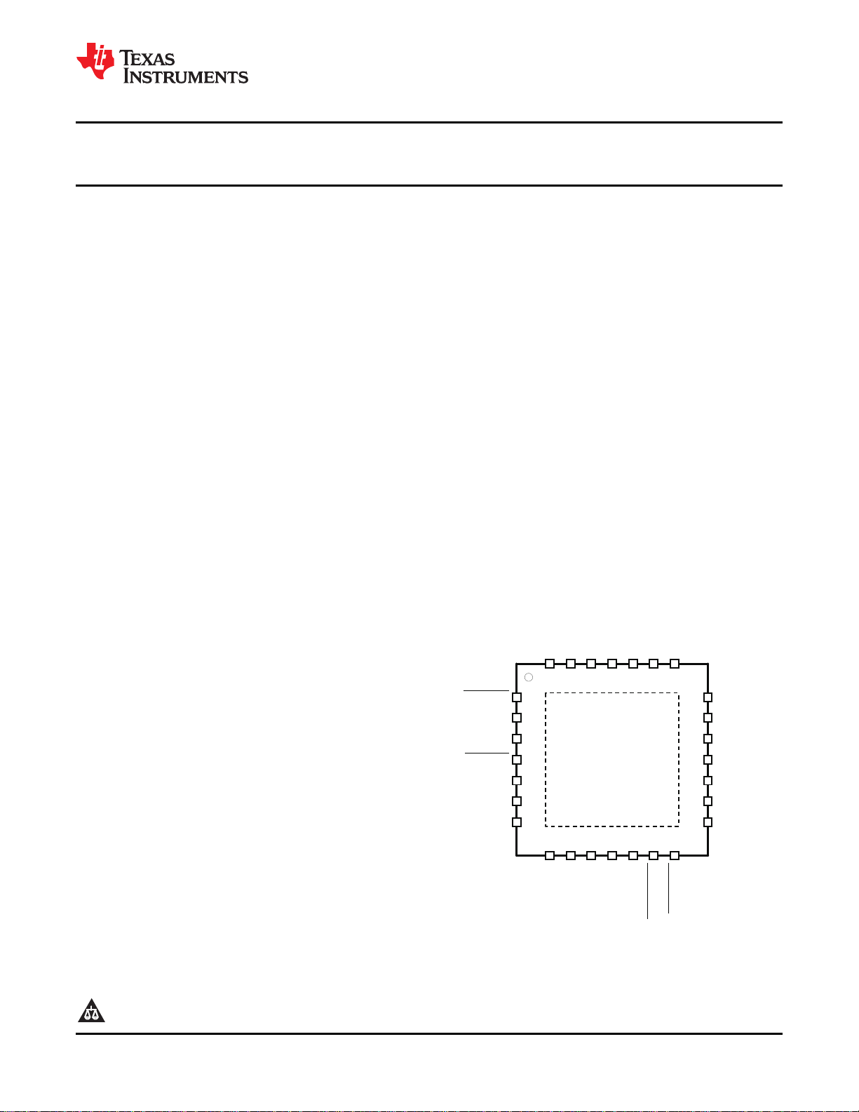
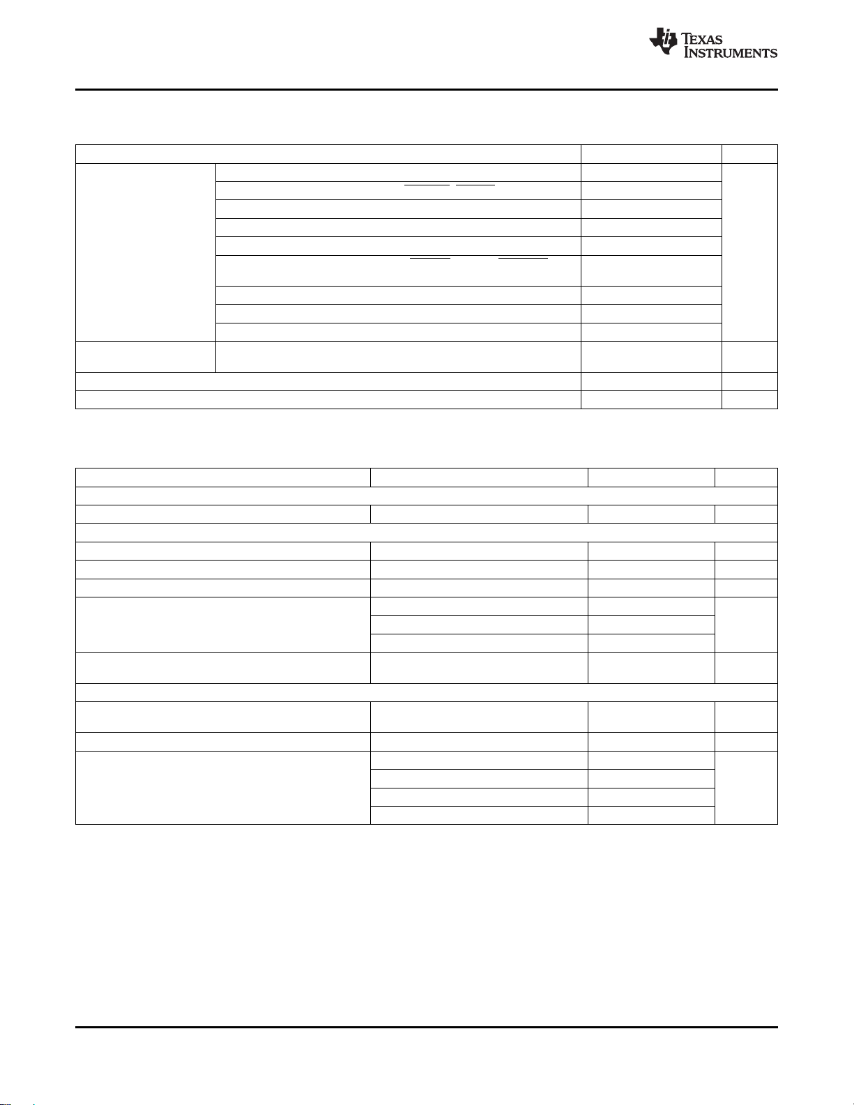
ACOP
bq24751
28LDQFN
TOP VIEW
LEARN
SRN
BAT
CELLS
SRP
SRSET
IADAPT
ACDRV
ACSET
CHGEN
ACN
ACP
ACDET
PVCC
BTST
HIDRV
REGNPHLODRV
PGND
OVPSET
AGND
VREF
VADJ
VDAC
ACGOOD
BATDRV
1
2
3
4
5
6
7
8 9 10 11 12 13 14
15
16
17
18
19
20
21
27 26 25 24 23 22
28
www.ti.com
............................................................................................................................................... SLUS734D – DECEMBER 2006 – REVISED MARCH 2009
Host-controlled Multi-chemistry Battery Charger with System Power Selector, AC
Over-Power Protection, and Programmable OVP
1
FEATURES
• NMOS-NMOS Synchronous Buck Converter
with 300 kHz Frequency and >95% Efficiency
• 30-ns Minimum Driver Dead-time and 99.5%
Maximum Effective Duty Cycle
• High-Accuracy Voltage and Current Regulation
– ± 0.5% Charge Voltage Accuracy
– ± 3% Charge Current Accuracy
– ± 3% Adapter Current Accuracy
– ± 2% Input Current Sense Amp Accuracy
• Integration
– Automatic System Power Selection From
AC/DC Adapter or Battery
– Internal Loop Compensation
– Internal Soft Start
• Safety
– Programmable Input Overvoltage
Protection (OVP)
– Dynamic Power Management (DPM) with
Status Indicator
– Programmable Inrush Adapter Power
(ACOP) and Overcurrent (ACOC) Limits
– Reverse-Conduction Protection Input FET
• Supports Two, Three, or Four Li+ Cells
• 5 – 24 V AC/DC-Adapter Operating Range
• Analog Inputs with Ratiometric Programming
via Resistors or DAC/GPIO Host Control
– Charge Voltage (4-4.512 V/cell)
– Charge Current (up to 10 A, with 10-m Ω
sense resistor)
– Adapter Current Limit (DPM)
• Status and Monitoring Outputs
– AC/DC Adapter Present with Programmable
Voltage Threshold
– Current Drawn from Input Source
• Battery Learn Cycle Control
• Supports Any Battery Chemistry: Li+, NiCd,
NiMH, Lead Acid, etc.
• Charge Enable
• 10- µ A Off-State Current
1
PRODUCTION DATA information is current as of publication date.
Products conform to specifications per the terms of the Texas
Instruments standard warranty. Production processing does not
necessarily include testing of all parameters.
Please be aware that an important notice concerning availability, standard warranty, and use in critical applications of Texas
Instruments semiconductor products and disclaimers thereto appears at the end of this data sheet.
bq24751
• 28-pin, 5x5-mm QFN package
APPLICATIONS
• Notebook and Ultra-Mobile Computers
• Portable Data Capture Terminals
• Portable Printers
• Medical Diagnostics Equipment
• Battery Bay Chargers
• Battery Back-up Systems
DESCRIPTION
The bq24751 is a high-efficiency, synchronous
battery charger with integrated compensation and
system power selector logic, offering low component
count for space-constrained multi-chemistry battery
charging applications. Ratiometric charge current and
voltage programming allows high regulation
accuracies, and can be either hardwired with resistors
or programmed by the system power-management
microcontroller using a DAC or GPIOs.
The bq24751 charges two, three, or four series Li+
cells, supporting up to 10 A of charge current, and is
available in a 28-pin, 5x5-mm thin QFN package.
Copyright © 2006 – 2009, Texas Instruments Incorporated
VREF
RAC
0.010 Ω
RSR
0.010 Ω
Q2 (ACFET)
SI4435
Q3(BATFET)
SI4435
N
P P
ACN
ACP
ACDRV
ACDET
/ACGOOD
SRSET
ACSET
VREF
CELLS
CHGEN
VDAC
VADJ
ADC
IADAPT
HOST
PVCC
BATDRV
HIDRV
N
PH
BTST
REGN
LODRV
PGND
SRP
SRN
P
PACK+
PACK-
SYSTEM
ADAPTER +
ADAPTER -
ACGOOD
AGND
bq24751
2.2 µF
C1
432 kΩ
1%
66.5 kΩ
1%
R1
R2
10 kΩ
R5
1 µF
C4
100 pF
C5
0.1 µF
C8
Q4
FDS6680A
Q5
FDS6680A
0.1 µF
C9
L1
8.2 µH
D1
BAT54
1 µF
C10
BAT
OVPSET
422 kΩ
1%
R3
71 kΩ
1%
R4
LEARN
ACOP
Q1 (ACFET)
SI4435
10 µF
C6
C15
0.1 µF
C16
0.47 µF
0.1 µF
C2
C3
2 Ω
R10
0.1 µF
PowerPad
10 µF
C7
10 µF
C12
C14
0.1 µF
C13
0.1 µF
C11
10 µF
GPIO
DAC
DAC
bq24751
SLUS734D – DECEMBER 2006 – REVISED MARCH 2009 ...............................................................................................................................................
These devices have limited built-in ESD protection. The leads should be shorted together or the device placed in conductive foam
during storage or handling to prevent electrostatic damage to the MOS gates.
DESCRIPTION (CONTINUED)
The bq24751 controls external switches to prevent battery discharge back to the input, connect the adapter to
the system, and to connect the battery to the system using 6-V gate drives for better system efficiency. For
maximum system safety, inrush-power limiting provides instantaneous response to high input voltage multiplied
by current. This AC Over-Power protection (ACOP) feature limits the input-switch power to the programmed level
on the ACOP pin, and latches off if the high-power condition persists to prevent overheating.
The bq24751 features Dynamic Power Management (DPM) and input power limiting. These features reduce
battery charge current when the input power limit is reached to avoid overloading the AC adapter when supplying
the load and the battery charger simultaneously. A highly-accurate current-sense amplifier enables precise
measurement of input current from the AC adapter to monitor the overall system power.
www.ti.com
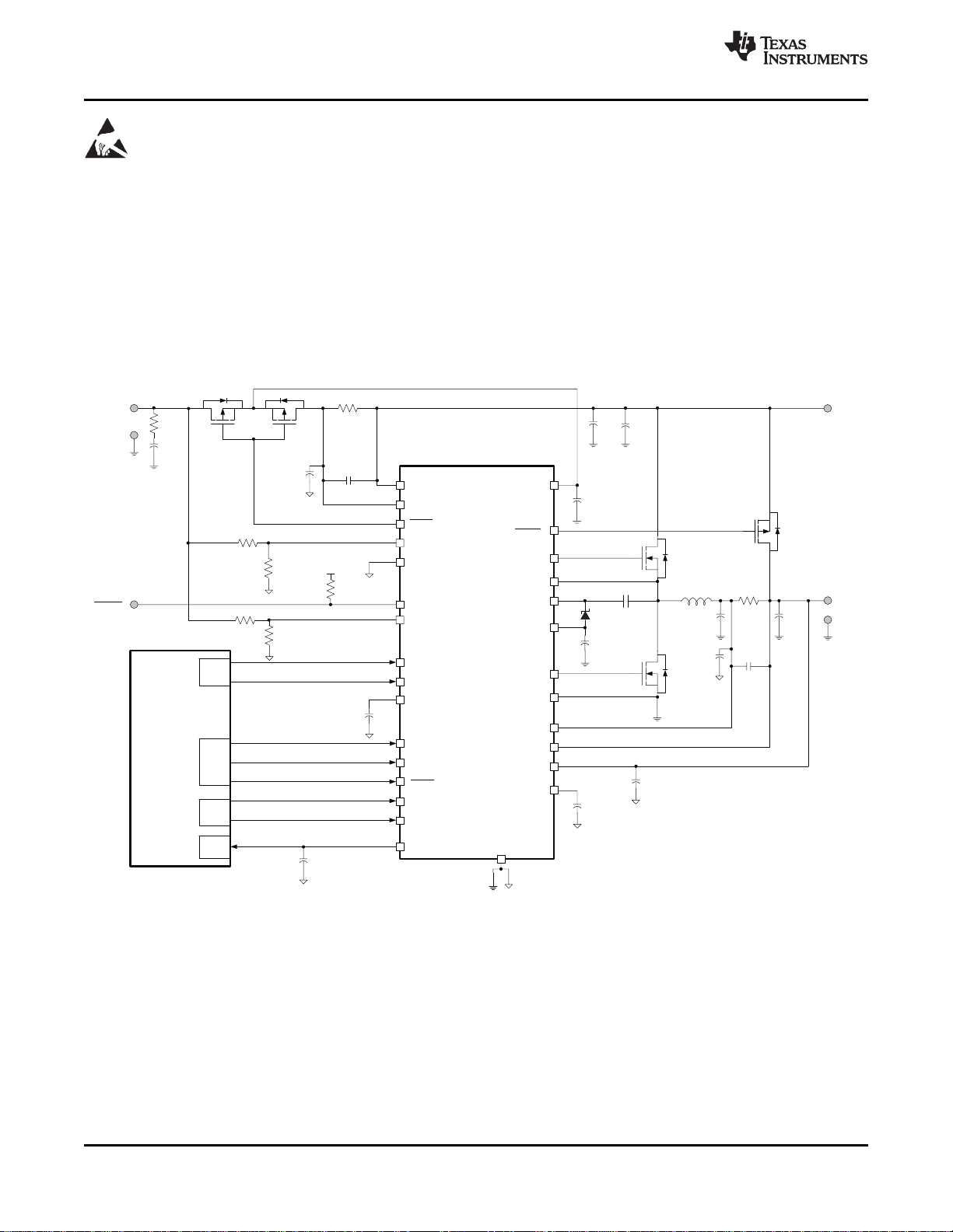
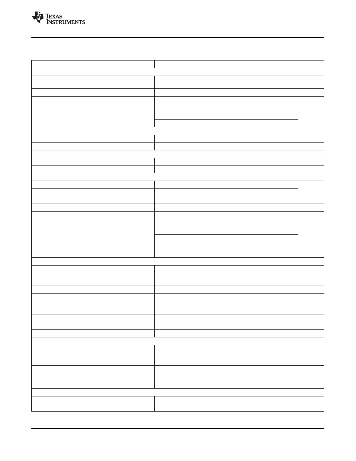
VIN= 20 V, V
Figure 1. Typical System Schematic, Voltage, and Current Programmed by DAC
2 Submit Documentation Feedback Copyright © 2006 – 2009, Texas Instruments Incorporated
= 3-cell Li-Ion, I
BAT
charge
= 3 A, I
adapter_limit
Product Folder Link(s) :bq24751
= 4 A

VREF
R
AC
0.010 Ω
R
SR
0.010 Ω
Q2 (ACFET)
SI4435
Q3(BATFET)
SI4435
N
P P
ACN
ACP
ACDRV
ACDET
ACGOOD
SRSET
ACSET
VREF
CELLS
CHGEN
VDAC
VADJ
ADC
IADAPT
HOST
PVCC
BATDRV
HIDRV
N
PH
BTST
REGN
LODRV
PGND
SRP
SRN
P
PACK+
PACK-
SYSTEM
ADAPTER +
ADAPTER -
ACGOOD
AGND
bq24751
2.2 µF
C1
10 kΩ
R5
1 µF
C4
100 pF
C5
0.1 µF
C8
Q4
FDS6680A
Q5
FDS6680A
0.1 µF
C9
L1
8.2 µH
D1
BAT54
1 µF
C10
BAT
OVPSET
422 kΩ
1%
R3
71 kΩ
1%
R4
LEARN
ACOP
Q1 (ACFET)
SI4435
10 µF
C6
C15
0.1 µF
C16
0.47 µF
0.1 µF
C2
C3
2 Ω
R10
0.1 µF
PowerPad
10 µF
C7
10 µF
C12
C14
0.1 µF
C13
0.1 µF
C11
10 µF
GPIO
VREF
VREF
100 kΩ
R8
66.5 kΩ
R9
100 kΩ
R7
43 kΩ
R11
VREF
REGN
432 kΩ
1%
66.5 kΩ
1%
R1
R2
bq24751
www.ti.com
............................................................................................................................................... SLUS734D – DECEMBER 2006 – REVISED MARCH 2009
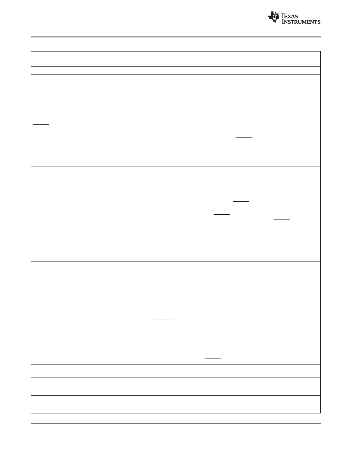
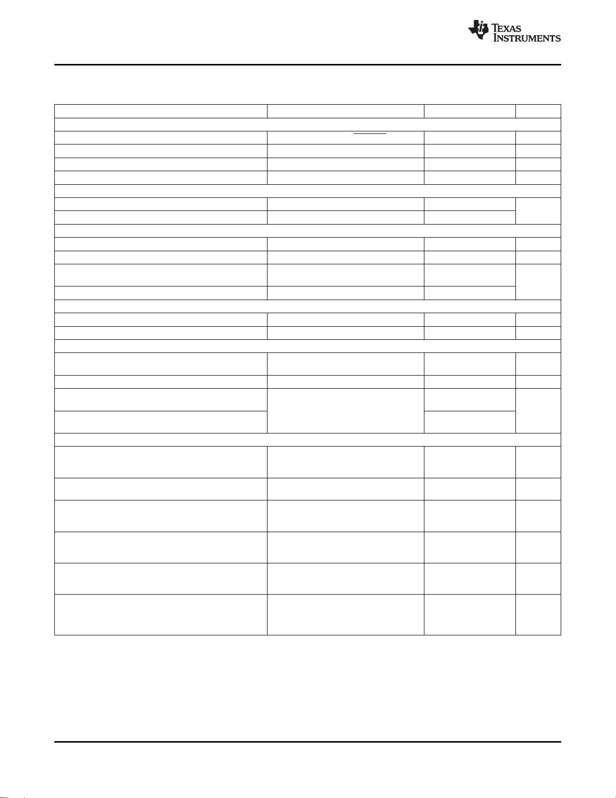
(1) Pull-up rail could be either VREF or other system rail.
(2) SRSET/ACSET could come from either DAC or resistor dividers.
VIN= 20 V, V
= 3-cell Li-Ion, I
BAT
= 3 A, I
charge
adapter_limit
= 4 A
Figure 2. Typical System Schematic, Voltage and Current Programmed by Resistor
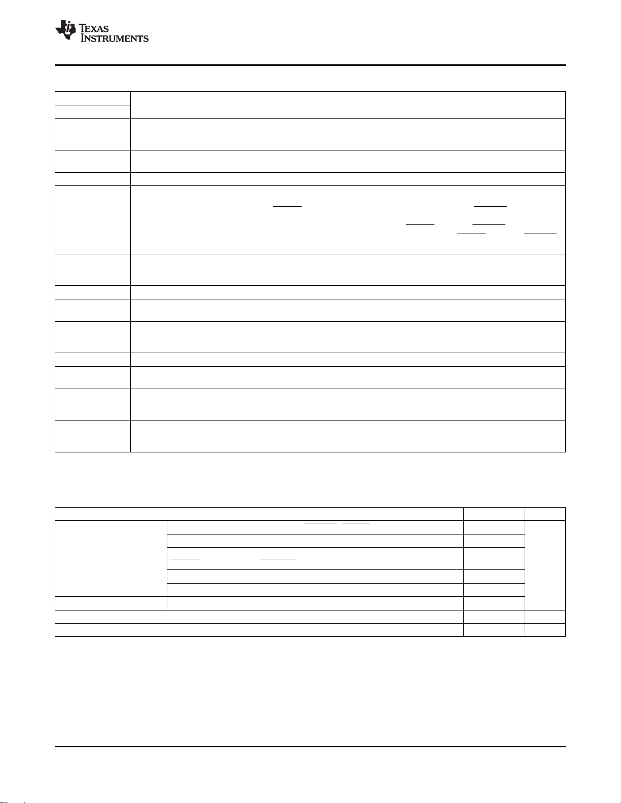
PART NUMBER PACKAGE QUANTITY
bq24751 28-PIN 5 x 5 mm QFN
PACKAGE THERMAL DATA
PACKAGE θ
QFN – RHD
(1) For the most current package and ordering information, see the Package Option Addendum at the end of this document, or see the TI
(2) This data is based on using the JEDEC High-K board and the exposed die pad is connected to a Cu pad on the board. This is
Web site at www.ti.com .
connected to the ground plane by a 2x3 via matrix.
(1) (2)
Copyright © 2006 – 2009, Texas Instruments Incorporated Submit Documentation Feedback 3
ORDERING INFORMATION
JA
39 ° C/W 2.36 W 0.028 W/ ° C
Product Folder Link(s) :bq24751
ORDERING NUMBER
(Tape and Reel)
bq24751RHDR 3000
bq24751RHDT 250
TA= 70 ° C DERATING FACTOR
POWER RATING ABOVE TA= 25 ° C
bq24751
SLUS734D – DECEMBER 2006 – REVISED MARCH 2009 ...............................................................................................................................................
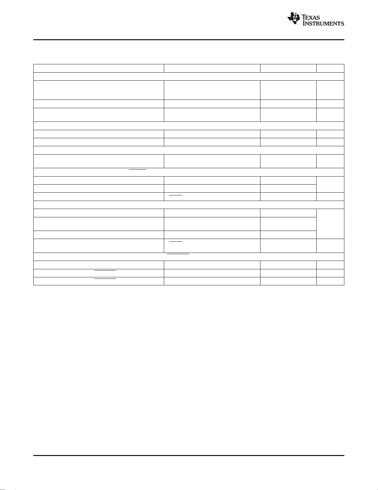
Table 1. PIN FUNCTIONS – 28-PIN QFN
PIN
NAME NO.
CHGEN 1 Charge enable active-low logic input. LO enables charge. HI disables charge.
ACN 2 differential-mode filtering. An optional 0.1- µ F ceramic capacitor is placed from ACN pin to AGND for common-mode
ACP 3
ACDRV 4
ACDET 5 input to ACDET pin to AGND pin. Adapter voltage is detected if ACDET-pin voltage is greater than 2.4 V. The I
ACSET 6
ACOP 7
OVPSET 8
AGND 9
VREF 10
VDAC 11 SRSET, and ACSET pin voltages, respectively. Place resistor dividers from VDAC to VADJ, SRSET, and ACSET pins
VADJ 12
ACGOOD 13
BATDRV 14 of the input BAT P-channel power MOSFET. Connect the source of the FET to the system load voltage node. Connect
IADAPT 15
SRSET 16 regulation set-point. Program by connecting a resistor divider from VDAC to SRSET to AGND; or by connecting the
BAT 17 pin to accurately sense the battery pack voltage. Place a 0.1- µ F capacitor from BAT to AGND close to the IC to filter
Adapter current sense resistor, negative input. A 0.1- µ F ceramic capacitor is placed from ACN to ACP to provide
filtering.
Adapter current sense resistor, positive input. A 0.1- µ F ceramic capacitor is placed from ACN to ACP to provide
differential-mode filtering. A 0.1- µ F ceramic capacitor is placed from ACP pin to AGND for common-mode filtering.
AC adapter to system-switch driver output. Connect directly to the gate of the ACFET P-channel power MOSFET and
the reverse conduction blocking P-channel power MOSFET. Connect both FETs as common-source. Connect the
ACFET drain to the system-load side. The PVCC should be connected to the common-source node to ensure that the
driver logic is always active when needed. If needed, an optional capacitor from gate to source of the ACFET is used
to slow down the ON and OFF times. The internal gate drive is asymmetrical, allowing a quick turn-off and slower
turn-on in addition to the internal break-before-make logic with respect to the BATDRV. The output goes into linear
regulation mode when the input sensed current exceeds the ACOC threshold. ACDRV is latched off after ACOP
voltage exceeds 2 V, to protect the charging system from an ACFET-overpower condition.
Adapter detected voltage set input. Program the adapter detect threshold by connecting a resistor divider from adapter
current sense amplifier is active when the ACDET pin voltage is greater than 0.6 V.
Adapter current set input. The voltage ratio of ACSET voltage versus VDAC voltage programs the input current
regulation set-point during Dynamic Power Management (DPM). Program by connecting a resistor divider from VDAC
to ACSET to AGND; or by connecting the output of an external DAC to the ACSET pin and connect the DAC supply to
the VDAC pin.
Input power limit set input. Program the input over-power time constant by placing a ceramic capacitor from ACOP to
AGND. The capacitor sets the time that the input current limit, ACOC, can be sustained before exceeding the
power-MOSFET power limit. When the ACOP voltage exceeds 2 V, then the ACDRV latches off to protect the charge
system from an over-power condition, ACOP. Reset latch by toggling ACDET or PVCC_UVLO.
Set input over voltage protection threshold. Charge is disabled and ACDRV is turned off if adapter input voltage is
higher than the OVPSET programmed threshold. Input overvoltage, ACOV, disables charge and ACDRV when
OVPSET > 3.1 V. ACOV does not latch. Program the overvoltage protection threshold by connecting a resistor divider
from adapter input to OVPSET pin to AGND pin.
Analog ground. Ground connection for low-current sensitive analog and digital signals. On PCB layout, connect to the
analog ground plane, and only connect to PGND through the PowerPad underneath the IC.
3.3-V regulated voltage output. Place a 1- µ F ceramic capacitor from VREF to AGND pin close to the IC. This voltage
could be used for ratiometric programming of voltage and current regulation.
Charge voltage set reference input. Connect the VREF or external DAC voltage source to the VDAC pin. Battery
voltage, charge current, and input current are programmed as a ratio of the VDAC pin voltage versus the VADJ,
to AGND for programming. A DAC could be used by connecting the DAC supply to VDAC and connecting the output
to VADJ, SRSET, or ACSET.
Charge voltage set input. The voltage ratio of VADJ voltage versus VDAC voltage programs the battery voltage
regulation set-point. Program by connecting a resistor divider from VDAC to VADJ, to AGND; or, by connecting the
output of an external DAC to VADJ, and connect the DAC supply to VDAC. VADJ connected to REGN programs the
default of 4.2 V per cell.
Valid adapter active-low detect logic open-drain output. Pulled low when Input voltage is above programmed ACDET.
Connect a 10-k Ω pullup resistor from ACGOOD to VREF, or to a different pullup-supply rail.
Battery to system switch driver output. Gate drive for the battery to system load BAT PMOS power FET to isolate the
system from the battery to prevent current flow from the system to the battery, while allowing a low impedance path
from battery to system and while discharging the battery pack to the system load. Connect this pin directly to the gate
the drain of the FET to the battery pack positive node. An optional capacitor is placed from the gate to the source to
slow down the switching times. The internal gate drive is asymmetrical to allow a quick turn-off and slower turn-on, in
addition to the internal break-before-make logic with respect to ACDRV.
Adapter current sense amplifier output. IADAPT voltage is 20 times the differential voltage across ACP-ACN. Place a
100-pF or less ceramic decoupling capacitor from IADAPT to AGND.
Charge current set input. The voltage ratio of SRSET voltage versus VDAC voltage programs the charge current
output of an external DAC to SRSET pin and connect the DAC supply to VDAC pin.
Battery voltage remote sense. Directly connect a kelvin sense trace from the battery pack positive terminal to the BAT
high-frequency noise.
DESCRIPTION
www.ti.com
ADAPT
4 Submit Documentation Feedback Copyright © 2006 – 2009, Texas Instruments Incorporated
Product Folder Link(s) :bq24751
bq24751
www.ti.com
NAME NO.
SRN 18 differential-mode filtering. An optional 0.1- µ F ceramic capacitor is placed from SRN pin to AGND for common-mode
SRP 19
CELLS 20 2, 3 or 4 cells selection logic input. Logic low programs 3 cell. Logic high programs 4 cell. Floating programs 2 cell.
LEARN 21 selector automatically switches to adapter if battery is discharged below LOWBAT (3 V). When adapter is present and
PGND 22 low-side power MOSFET, to ground connection of in put and output capacitors of the charger. Only connect to AGND
LODRV 23 PWM low side driver output. Connect to the gate of the low-side power MOSFET with a short trace.
REGN 24
PH 25 drain, high-side power MOSFET source, and output inductor). Connect the 0.1- µ F bootstrap capacitor from from PH to
HIDRV 26 PWM high side driver output. Connect to the gate of the high-side power MOSFET with a short trace.
BTST 27
PVCC 28 and source of reverse-blocking power P-channel MOSFET. Place a 1- µ F ceramic capacitor from PVCC to PGND pin
PowerPad to the board, and have vias on the PowerPad plane connecting to AGND and PGND planes. It also serves as a
............................................................................................................................................... SLUS734D – DECEMBER 2006 – REVISED MARCH 2009
Table 1. PIN FUNCTIONS – 28-PIN QFN (continued)
PIN
Charge current sense resistor, negative input. A 0.1- µ F ceramic capacitor is placed from SRN to CSP to provide
filtering.
Charge current sense resistor, positive input. A 0.1- µ F ceramic capacitor is placed from SRN to SRP to provide
differential-mode filtering. A 0.1- µ F ceramic capacitor is placed from SRP pin to AGND for common-mode filtering.
Learn mode logic input control pin — logic high to override system selector when adapter is present, the battery is
discharged to recalibrate the battery-pack gas gauge. When adapter is present and LEARN is high, battery charging is
disabled, the adapter is disconnected ( ACDRV is off), and the battery is connected to system ( BATDRV is on). Sytem
LEARN is low, the adapter is connected to system in normal selector logic ( ACDRV is on and BATDRV is off), allowing
battery charging. If adapter is not present, the battery is always connected to the system ( ACDRV is off and BATDRV
is on).
Power ground. Ground connection for high-current power converter node. On PCB layout, connect directly to source of
through the PowerPad underneath the IC.
PWM low side driver positive 6-V supply output. Connect a 1- µ F ceramic capacitor from REGN to PGND, close to the
IC. Use for high-side driver bootstrap voltage by connecting a small-signal Schottky diode from REGN to BTST.
PWM high side driver negative supply. Connect to the phase switching node (junction of the low-side power MOSFET
BTST.
PWM high side driver positive supply. Connect a 0.1- µ F bootstrap ceramic capacitor from BTST to PH. Connect a
small bootstrap Schottky diode from REGN to BTST.
IC power positive supply. Connect to the common-source (diode-OR) point: source of high-side P-channel MOSFET
close to the IC.
Exposed pad beneath the IC. AGND and PGND star-connected only at the PowerPad plane. Always solder PowerPad
thermal pad to dissipate the heat.
DESCRIPTION
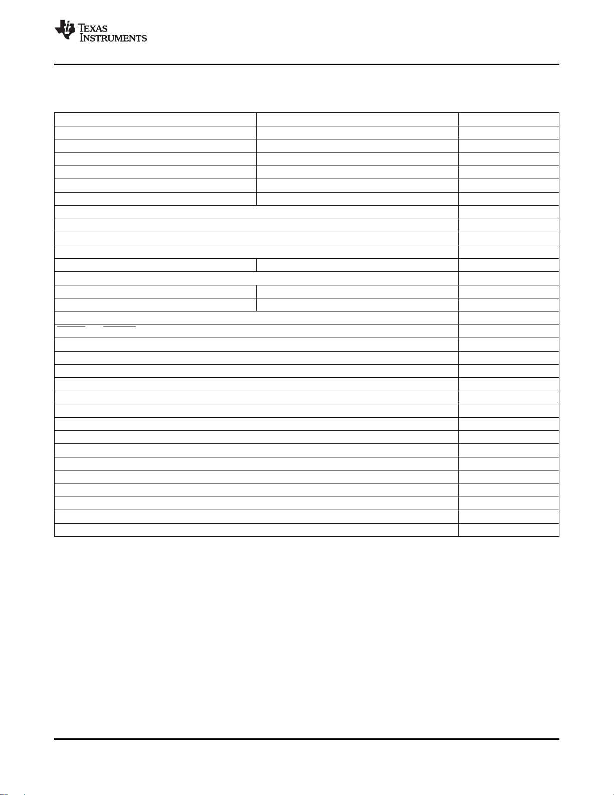
ABSOLUTE MAXIMUM RATINGS
over operating free-air temperature range (unless otherwise noted)
PVCC, ACP, ACN, SRP, SRN, BAT, BATDRV, ACDRV – 0.3 to 30
PH – 1 to 30
Voltage range
Maximum difference voltage ACP – ACN, SRP – SRN, AGND – PGND – 0.5 to 0.5
Junction temperature range – 40 to 155 ° C
Storage temperature range – 55 to 155 ° C
(1) Stresses beyond those listed under absolute maximum ratings may cause permanent damage to the device. These are stress ratings
only, and functional operation of the device at these or any other conditions beyond those indicated under recommended operating
conditions is not implied. Exposure to absolute-maximum-rated conditions for extended periods may affect device reliability.
(2) All voltages are with respect to GND if not specified. Currents are positive into, negative out of the specified terminal. Consult Packaging
Section of the data book for thermal limitations and considerations of packages.
Copyright © 2006 – 2009, Texas Instruments Incorporated Submit Documentation Feedback 5
REGN, LODRV, VREF, VDAC, VADJ, ACSET, SRSET, ACDET, ACOP, – 0.3 to 7
CHGEN, CELLS, STAT, ACGOOD, LEARN, OVPSET
VREF, IADAPT – 0.3 to 3.6
BTST, HIDRV with respect to AGND and PGND – 0.3 to 36
Product Folder Link(s) :bq24751
(1) (2)
VALUE UNIT
V
bq24751
SLUS734D – DECEMBER 2006 – REVISED MARCH 2009 ...............................................................................................................................................
RECOMMENDED OPERATING CONDITIONS
over operating free-air temperature range (unless otherwise noted)
MIN NOM MAX UNIT
PH – 1 24
PVCC, ACP, ACN, SRP, SRN, BAT, BATDRV, ACDRV 0 24
REGN, LODRV 0 6.5
VDAC, IADAPT 0 3.6
Voltage range V
Maximum difference ACP – ACN, SRP – SRN – 0.3 0.3 V
voltage
Junction temperature range, T
Storage temperature range, T
VREF 3.3
ACSET, SRSET, TS, ACDET, ACOP, CHGEN, CELLS, ACGOOD, 0 5.5
LEARN, OVPSET
VADJ 0 6.5
BTST, HIDRV with respect to AGND and PGND 0 30
AGND, PGND – 0.3 0.3
J
stg
– 55 125 ° C
– 40 150 ° C
ELECTRICAL CHARACTERISTICS
7.0 V ≤ V
OPERATING CONDITIONS
V
PVCC_OP
CHARGE VOLTAGE REGULATION
V
BAT_REG_RNG
V
VDAC_OP
V
ADJ_OP
CHARGE CURRENT REGULATION
V
IREG_CHG
V
SRSET_OP
≤ 24 V, 0 ° C < TJ< +125 ° C, typical values are at TA= 25 ° C, with respect to AGND (unless otherwise noted)
PVCC
PARAMETER TEST CONDITIONS MIN TYP MAX UNIT
PVCC Input voltage operating range 5.0 24.0 V
BAT voltage regulation range 4-4.512 V per cell, times 2,3,4 cells 8 18.048 V
VDAC reference voltage range 2.6 3.6 V
VADJ voltage range 0 REGN V
8 V, 8.4 V, 9.024 V – 0.5% 0.5%
Charge voltage regulation accuracy 12 V, 12.6 V, 13.536 V – 0.5% 0.5%
16 V, 16.8 V, 18.048 V – 0.5% 0.5%
Charge voltage regulation set to VADJ connected to REGN, 8.4 V, 12.6 V,
default to 4.2 V per cell 16.8 V
Charge current regulation differential V
voltage range
IREG_CHG
= V
– V
SRP
SRN
– 0.5% 0.5%
SRSET voltage range 0 VDAC V
V
IREG_CHG
V
Charge current regulation accuracy %
IREG_CHG
V
IREG_CHG
V
IREG_CHG
= 40 – 100 mV – 3 3
= 20 mV – 5 5
= 5 mV – 25 25
= 1.5 mV (V
> 4V) – 33 33
BAT
0 100 mV
www.ti.com
6 Submit Documentation Feedback Copyright © 2006 – 2009, Texas Instruments Incorporated
Product Folder Link(s) :bq24751
www.ti.com
............................................................................................................................................... SLUS734D – DECEMBER 2006 – REVISED MARCH 2009
ELECTRICAL CHARACTERISTICS (continued)
7.0 V ≤ V
INPUT CURRENT REGULATION
V
IREG_DPM
V
ACSET_OP
VREF REGULATOR
V
VREF_REG
I
VREF_LIM
REGN REGULATOR
V
REGN_REG
I
REGN_LIM
ADAPTER CURRENT SENSE AMPLIFIER
V
ACP/N_OP
V
IADAPT
I
IADAPT
A
IADAPT
I
IADAPT_LIM
C
IADAPT_MAX
ACDET COMPARATOR
V
ACDET_CHG
V
ACDET_CHG_HYS
V
ACDET_BIAS
V
ACDET_BIAS_HYS
PVCC / BAT COMPARATOR (REVERSE DISCHARGING PROTECTION)
V
PVCC-BAT_OP
V
PVCC-BAT_FALL
V
PVCC-BAT__HYS
INPUT UNDERVOLTAGE LOCK-OUT COMPARATOR (UVLO)
V
UVLO
V
UVLO_HYS
≤ 24 V, 0 ° C < TJ< +125 ° C, typical values are at TA= 25 ° C, with respect to AGND (unless otherwise noted)
PVCC
PARAMETER TEST CONDITIONS MIN TYP MAX UNIT
Adapter current regulation differential V
voltage range
ACSET voltage range 0 VDAC V
Input current regulation accuracy %
VREF regulator voltage V
VREF current limit V
REGN regulator voltage V
REGN current limit V
Input common mode range Voltage on ACP/ACN 0 24
IADAPT output voltage range 0 2
IADAPT output current 0 1 mA
Current sense amplifier voltage gain A
Adapter current sense accuracy %
Output current limit V
Maximum output load capacitance For stability with 0 mA to 1 mA load 100 pF
ACDET adapter-detect rising Min voltage to enable charging, V
threshold rising
ACDET falling hysteresis V
ACDET rising deglitch VACDET rising 518 700 908 ms
ACDET falling deglitch VACDET falling 7 9 11 ms
ACDET enable-bias rising threshold Min voltage to enable all bias, V
Adapter present falling hysteresis V
ACDET rising deglitch V
ACDET falling deglitch V
Differential Voltage from PVCC to – 20 24 V
BAT
PVCC to BAT falling threshold V
PVCC to BAT hysteresis 50 mV
PVCC to BAT Rising Deglitch V
PVCC to BAT Falling Deglitch V
AC Under-voltage rising threshold Measured on PVCC 3.5 4 4.5 V
AC Under-voltage hysteresis, falling 260 mV
= V
IREG_DPM
V
IREG_DPM
V
IREG_DPM
V
IREG_DPM
V
IREG_DPM
> 0.6 V, 0-30 mA 3.267 3.3 3.333 V
ACDET
= 0 V, V
VREF
> 0.6 V, 0-75 mA, PVCC > 10 V 5.6 5.9 6.2 V
ACDET
= 0 V, V
REGN
= V
IADAPT
V
IREG_DPM
V
IREG_DPM
V
IREG_DPM
V
IREG_DPM
= 0 V 1 mA
IADAPT
falling 40 mV
ACDET
rising
falling 20 mV
ACDET
rising 10 µ s
ACDET
falling 10 µ s
ACDET
– V
PVCC
– V
PVCC
– V
PVCC
– V
ACP
ACN
= 40 – 100 mV – 3 3
= 20 mV – 5 5
= 5 mV – 25 25
= 1.5 mV – 33 33
> 0.6 V 35 75 mA
ACDET
> 0.6 V 90 135 mA
ACDET
/ V
IADAPT
IREG_DPM
= 40 – 100 mV – 2 2
= 20 mV – 3 3
= 5 mV – 25 25
= 1.5 mV – 33 33
ACDET
ACDET
to turn off ACFET 140 185 240 mV
BAT
> V
BAT
PVCC-BAT_RISE
< V
BAT
PVCC-BAT_FALL
0 100 mV
20 V/V
2.376 2.40 2.424 V
0.56 0.62 0.68 V
7 9 11 ms
bq24751
V
6 µ s
Copyright © 2006 – 2009, Texas Instruments Incorporated Submit Documentation Feedback 7
Product Folder Link(s) :bq24751
bq24751
SLUS734D – DECEMBER 2006 – REVISED MARCH 2009 ...............................................................................................................................................
ELECTRICAL CHARACTERISTICS (continued)
7.0 V ≤ V
ACN / BAT COMPARATOR
V
ACN-BAT_FALL
V
ACN-BAT_HYS
BAT OVERVOLTAGE COMPARATOR
V
OV_RISE
V
OV_FALL
BAT SHORT (UNDERVOLTAGE) COMPARATOR
V
BAT_SHORT_FALL
V
BAT_SHORT_HYS
CHARGE OVERCURRENT COMPARATOR
V
OC
CHARGE UNDERCURRENT COMPARATOR (SYNCHRONOUS TO NON-SYNCHRONOUS TRANSITION)
V
ISYNSET_FALL
V
ISYNSET_HYS
INPUT OVER-POWER COMPARATOR (ACOP)
V
ACOC
V
ACOC_CEILING
V
ACOP
K
ACOP
I
ACOP_SINK
≤ 24 V, 0 ° C < TJ< +125 ° C, typical values are at TA= 25 ° C, with respect to AGND (unless otherwise noted)
PVCC
PARAMETER TEST CONDITIONS MIN TYP MAX UNIT
ACN to BAT falling threshold V
– V
ACN
to turn on BATDRV 175 285 340 mV
BAT
ACN to BAT hysteresis 50 mV
ACN to BAT rising deglitch V
ACN to BAT falling deglitch V
– V
ACN
ACN
> V
BAT
– V
< V
BAT
Overvoltage rising threshold As percentage of V
Overvoltage falling threshold As percentage of V
BAT short falling threshold 2.755 2.9 3.045 V/cell
BAT short hysteresis 250 mV/cell
V
> V
BAT
BAT short rising deglitch 1.5
Detection delay
BAT short falling deglitch V
BAT_SHORT
< V
BAT
BAT_SHORT
Charge over-current falling threshold As percentage of I
Minimum Current Limit (SRP-SRN) 50 mV
Charge undercurrent falling threshold 9.75 13 16.25 mV
Changing from synchronous to
non-sysnchronous
Charge undercurrent rising hysteresis 8 mV
Charge undercurrent, falling-current 20
deglitch
Charge undercurrent, rising-current 640
V
IREG_DPM
< V
ISYNSET
deglitch
ACOC Gain for initial ACOC current Begins 700 ms after ACDET %
limit (Percentage of programmed Input current limited to this threshold for 150 V
VIREG_DPM) fault protection
Maximum ACOC input current limit Internally limited ceiling
(V
– V
ACP
)max V
ACN
ACOC_MAX
= (V
ACP
ACOP Latch Blankout Time with Begins 700 ms after ACDET
ACOC active (does not allow ACOP latch-off, and no 2 ms
(begins 700 ms after ACDET) ACOP source current)
ACOP pin latch-off threshold voltage
(See ACOP in Terminal Functions 1.95 2 2.05
table ) V
Gain for ACOP Source Current when
in ACOC
Current source on when in ACOC limit.
Function of voltage across power FET 18 µ A / V
I
ACOP_SOURCE
= K
ACOP Sink Current when not in µ A
ACOC
ACOP Latch is reset by going below
Current sink on when not in ACOC 5
ACDET or UVLO
www.ti.com
ACN-BAT_RISE
ACN-BAT_FALL
BAT_REG
BAT_REG
+V
BAT_SHORT_HYS
20 µ s
6 µ s
104
102
%
s
1.5
REG_CHG
145 %
µ s
IREG_DPM
– V
)max
ACN
× (V
ACOP
-V
PVCC
)
ACP
100 mV
8 Submit Documentation Feedback Copyright © 2006 – 2009, Texas Instruments Incorporated
Product Folder Link(s) :bq24751
www.ti.com
............................................................................................................................................... SLUS734D – DECEMBER 2006 – REVISED MARCH 2009
ELECTRICAL CHARACTERISTICS (continued)
7.0 V ≤ V
INPUT OVERVOLTAGE COMPARATOR (ACOV)
V
ACOV
V
ACOV_HYS
THERMAL SHUTDOWN COMPARATOR
T
SHUT
T
SHUT_HYS
BATTERY SWITCH ( BATDRV) DRIVER
R
DS_BAT_OFF
R
DS_BAT_ON
V
BATDRV_REG
AC SWITCH ( ACDRV) DRIVER
R
DS_AC_OFF
R
DS_AC_ON
V
ACDRV_REG
AC / BAT MOSFET DRIVERS TIMING
PWM HIGH SIDE DRIVER (HIDRV)
R
DS_HI_ON
R
DS_HI_OFF
V
BTST_REFRESH
PWM LOW SIDE DRIVER (LODRV)
R
DS_LO_ON
R
DS_LO_OFF
PWM DRIVERS TIMING
PWM OSCILLATOR
F
SW
V
RAMP_HEIGHT
≤ 24 V, 0 ° C < TJ< +125 ° C, typical values are at TA= 25 ° C, with respect to AGND (unless otherwise noted)
PVCC
PARAMETER TEST CONDITIONS MIN TYP MAX UNIT
AC Overvoltage rising threshold on
OVPSET Measured on OVPSET 3.007 3.1 3.193 V
(See OVPSET in Table 1 )
AC Over-voltage rising deglitch 1.3
AC Over-voltage falling deglitch 1.3
Thermal shutdown rising temperature Temperature Increasing 155 ° C
Thermal shutdown hysteresis, falling 20 ° C
BATFET Turn-off resistance V
BATFET Turn-on resistance V
BATFET drive voltage 6.5 V
BATFET Power-up delay 518 700 908 ms
ACFET turn-off resistance V
ACFET turn-on resistance V
ACFET drive voltage 6.5 V
ACFET Power-up Delay 518 700 908 ms
Driver dead time Dead time when switching between 10 µ s
High side driver turn-on resistance V
High side driver turn-off resistance V
Bootstrap refresh comparator V
threshold voltage is requested
Low side driver turn-on resistance REGN = 6 V, tested at 100 mA 3 6 Ω
Low side driver turn-off resistance REGN = 6 V, tested at 100 mA 0.6 1.2 Ω
Driver Dead Time — Dead time when
switching between LODRV and
HIDRV. No load at LODRV and
HIDRV
PWM switching frequency 240 360 kHz
PWM ramp height As percentage of PVCC 6.6 %PVCC
> 5 V 160 Ω
ACN
> 5 V 3 k Ω
ACN
V
BATDRV_REG
V
ACN
= V
– V
> 5 V and BATFET is on
ACN
when
BATDRV
Delay to turn off BATFET after adapter is
detected (after ACDET > 2.4)
> 5 V 80 Ω
PVCC
> 5 V 2.5 k Ω
PVCC
V
ACDRV_REG
V
PVCC
= V
> 5 V and ACFET is on
– V
PVCC
when
ACDRV
Delay to turn on ACFET after adapter is
detected (after ACDET > 2.4)
ACDRV and BATDRV
– V
BTST
BTST
BTST
= 5.5 V, tested at 100 mA 3 6 Ω
PH
– V
= 5.5 V, tested at 100 mA 0.7 1.4 Ω
PH
– V
when low side refresh pulse
PH
4 V
30 ns
bq24751
ms
Copyright © 2006 – 2009, Texas Instruments Incorporated Submit Documentation Feedback 9
Product Folder Link(s) :bq24751
bq24751
SLUS734D – DECEMBER 2006 – REVISED MARCH 2009 ...............................................................................................................................................
ELECTRICAL CHARACTERISTICS (continued)
7.0 V ≤ V
QUIESCENT CURRENT
I
OFF_STATE
I
AC
I
BATQ_CD
INTERNAL SOFT START (8 steps to regulation current)
CHARGER SECTION POWER-UP SEQUENCING
LOGIC INPUT PIN CHARACTERISTICS ( CHGEN, LEARN)
V
IN_LO
V
IN_HI
I
BIAS
LOGIC INPUT PIN CHARACTERISTICS (CELLS)
V
IN_LO
V
IN_MID
V
IN_HI
I
BIAS_FLOAT
OPEN-DRAIN LOGIC OUTPUT PIN CHARACTERISTICS ( ACGOOD)
V
OUT_LO
≤ 24 V, 0 ° C < TJ< +125 ° C, typical values are at TA= 25 ° C, with respect to AGND (unless otherwise noted)
PVCC
PARAMETER TEST CONDITIONS MIN TYP MAX UNIT
Total off-state quiescent current into V
pins: SRP, SRN, BAT, BTST, PH, V
PVCC, ACP, ACN
Adapter quiescent current V
BAT
PVCC
PVCC
= 16.8 V, V
Total quiescent current into pins: Adapter present, VACDET > 2.4 V,
SRP, SRN, BAT, BTST, PH charge disabled
Soft start steps 8 step
Soft start step time 1.7 ms
Charge-enable delay after power-up 518 700 908 ms
Delay from when adapter is detected to
when the charger is allowed to turn on
Input low threshold voltage 0.8
Input high threshold voltage 2.1
Input bias current V
CHGEN
Input low threshold voltage, 3 cells CELLS voltage falling edge 0.5
Input mid threshold voltage, 2 cells CELLS voltage rising for MIN,
CELLS voltage falling for MAX
Input high threshold voltage, 4 cells CELLS voltage rising 2.5
Input bias float current for 2-cell V
selection
CHGEN
Output low saturation voltage Sink Current = 5 mA 0.5 V
Delay, ACGOOD falling 518 700 908 ms
Delay, ACGOOD rising 10 ms
www.ti.com
< 0.6 V,
> 5 V, TJ= 0 to 85 ° C 7 10 µ A
ACDET
= 20 V, charge disabled 2.8 4 mA
100 200 µ A
= 0 to V
REGN
1 µ A
0.8 1.8 V
= 0 to V
REGN
– 1 1 µ A
V
10 Submit Documentation Feedback Copyright © 2006 – 2009, Texas Instruments Incorporated
Product Folder Link(s) :bq24751
bq24751
www.ti.com
............................................................................................................................................... SLUS734D – DECEMBER 2006 – REVISED MARCH 2009
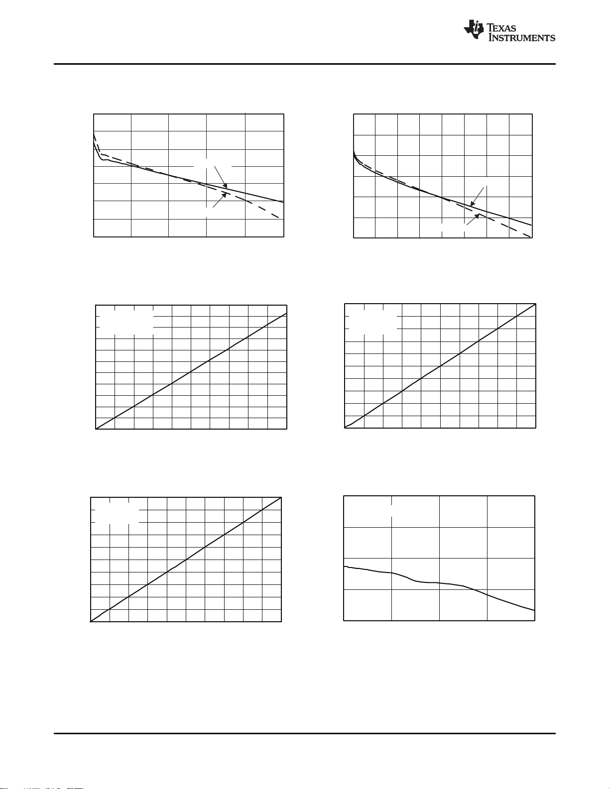
TYPICAL CHARACTERISTICS
Table of Graphs
(1)
Y X FIgure
VREF Load and Line Regulation vs Load Current Figure 3
REGN Load and Line Regulation vs Load Current Figure 4
BAT Voltage vs VADJ/VDAC Ratio Figure 5
Charge Current vs SRSET/VDAC Ratio Figure 6
Input Current vs ACSET/VDAC Ratio Figure 7
BAT Voltage Regulation Accuracy vs Charge Current Figure 8
BAT Voltage Regulation Accuracy Figure 9
Charge Current Regulation Accuracy Figure 10
Input Current Regulation (DPM) Accuracy Figure 11
V
Input Current Sense Amplifier Accuracy Figure 12
IADAPT
Input Regulation Current (DPM), and Charge Current vs System Current Figure 13
Transient System Load (DPM) Response Figure 14
Charge Current Regulation vs BAT Voltage Figure 15
Efficiency vs Battery Charge Current Figure 16
Battery Removal (from Constant Current Mode) Figure 17
ACDRV and BATDRV Startup Figure 18
REF and REGN Startup Figure 19
System Selector on Adapter Insertion with 390- µ F SYS-to-PGND System Capacitor Figure 20
System Selector on Adapter Removal with 390- µ F SYS-to-PGND System Capacitor Figure 21
System Selector LEARN Turn-On with 390- µ F SYS-to-PGND System Capacitor Figure 22
System Selector LEARN Turn-Off with 390- µ F SYS-to-PGND System Capacitor Figure 23
System Selector on Adapter Insertion Figure 24
Selector Gate Drive Voltages, 700 ms delay after ACDET Figure 25
Charger on Adapter Removal Figure 26
Charge Enable / Disable and Current Soft-Start Figure 27
Nonsynchronous to Synchronous Transition Figure 28
Synchronous to Nonsynchronous Transition Figure 29
Near 100% Duty Cycle Bootstrap Recharge Pulse Figure 30
Battery Shorted Charger Response, Over Current Protection (OCP) and Charge Current Regulation Figure 31
Continuous Conduction Mode (CCM) Switching Waveforms Figure 32
Discontinuous Conduction Mode (DCM) Switching Waveforms Figure 33
(1) Test results based on Figure 2 application schematic. VIN= 20 V, V
otherwise specified.
= 3-cell LiIon, I
BAT
= 3 A, I
CHG
ADAPTER_LIMIT
= 4 A, TA= 25 ° C, unless
Copyright © 2006 – 2009, Texas Instruments Incorporated Submit Documentation Feedback 11
Product Folder Link(s) :bq24751
-0.20
-0.10
0
0.10
0.20
0.30
0.40
0.50
0 10 20 30 40 50
VREF-LoadCurrent-mA
RegulationError-%
PVCC=10V
PVCC=20V
-3
-2.50
-2
-1.50
-1
-0.50
0
0 10 20 30 40 50 60 70 80
REGN-LoadCurrent-mA
RegulationError-%
PVCC=10V
PVCC=20V
0
1
2
3
4
5
6
7
8
9
10
0 0.1 0.2 0.3 0.4 0.5 0.6 0.7 0.8 0.9 1
SRSET/VDACRatio
ChargeCurrentRegulation- A
SRSET Varied,
4-Cell,
Vbat=16V
16
16.2
16.4
16.6
16.8
17
17.2
17.4
17.6
17.8
18
18.2
0 0.1 0.2 0.3 0.4 0.5 0.6 0.7 0.8 0.9 1
VADJ/VDACRatio
V
oltageRegulation-V
VADJ=0-VDAC,
4-Cell,
NoLoad
V =16.8V
reg
-0.2
-0.1
0
0.1
0.2
0
2000
4000
6000
8000
ChargeCurrent-mA
RegulationError-%
0
1
2
3
4
6
7
8
9
10
0 0.1 0.2 0.3 0.4 0.5 0.6 0.7 0.8 0.9 1
ACSET/VDACRatio
InputCurrentRegulation- A
ACSET Varied,
4-Cell,
Vbat=16V
5
bq24751
SLUS734D – DECEMBER 2006 – REVISED MARCH 2009 ...............................................................................................................................................
www.ti.com
VREF LOAD AND LINE REGULATION REGN LOAD AND LINE REGULATION
vs vs
Load Current LOAD CURRENT
Figure 3. Figure 4.
BAT VOLTAGE CHARGE CURRENT
vs vs
VADJ/VDAC RATIO SRSET/VDAC RATIO
Figure 5. Figure 6.
INPUT CURRENT BAT VOLTAGE REGULATION ACCURACY
ACSET/VDAC RATIO CHARGE CURRENT
12 Submit Documentation Feedback Copyright © 2006 – 2009, Texas Instruments Incorporated
Figure 7. Figure 8.
vs vs
Product Folder Link(s) :bq24751
 Loading...