

Page 1

查询BQ2060A供应商
bq2060A
SBS v1.1-Compliant Gas Gauge IC
Features
Provides accurate measurement
>
of available charge in NiCd,
NiMH, Li-Ion, and lead-acid
batteries
Supports SBS Smart Battery
>
Data Specification v1.1
Supports the 2-wire SMBus v1.1
>
interface with PEC or 1-wire
HDQ16
Reports individual cell voltages
>
Monitors and provides control to
>
charge and discharge FETs in
Li-Ion protection circuit
Provides 15-bit resolution for
>
voltage, temperature, and current measurements
Measures charge flow using a
>
V-to-F converter with offset of
less than 16µV after calibration
>
Consumes less than 0.5mW operating
>
Drives a 4- or 5-segment LED
display for remaining capacity indication
>
28-pin 150-mil SSOP
General Description
The bq2060A SBS-Compliant Gas
Gauge IC for battery pack or
in-system installation maintains an
accurate record of available charge in
rechargeable batteries. The bq2060A
monitors capacity and other critical
battery parameters for NiCd, NiMH,
Li-Ion, and lead-acid chemistries.
The bq2060A uses a V-to-F converter
with automatic offset error correction
for charge and discharge counting.
For voltage, temperature, and current
reporting, the bq2060A uses an
A-to-D converter. The onboard ADC
also monitors individual cell voltages
in a Li-Ion battery pack and allows
the bq2060A to generate control sig
nals that may be used in conjunction
with a pack supervisor to enhance
pack safety.
The bq2060A supports the smart battery data (SBData) commands and
charge-control functions. It communicates data using the system management bus (SMBus) 2-wire protocol or
the Benchmarq 1-wire HDQ16 protocol. The data available include the
battery’s remaining capacity, temperature, voltage, current, and remain
ing run-time predictions. The
Pin Connections Pin Names
bq2060A provides LED drivers and a
push-button input to depict remaining
battery capacity from full to empty in
20% or 25% increments witha4or
5-segment display.
The bq2060A works with an external
EEPROM. The EEPROM stores the
configuration information for the
bq2060A, such as the battery’s chem
istry, self-discharge rate, rate com
pensation factors, measurement cali
bration, and design voltage and ca
pacity. The bq2060A uses the pro
grammable self-discharge rate and
other compensation factors stored in
the EEPROM to accurately adjust re
maining capacity for use and standby
conditions based on time, rate, and
-
temperature. The bq2060A also auto
matically calibrates or learns the true
battery capacity in the course of a discharge cycle from near-full to
near-emptylevels.
The REG output regulates the operating voltage for the bq2060A from the
battery cell stack using an external
JFET .
-
-
-
-
-
-
-
-
HDQ16
ESDA
SLUS500A–OCTOBER 2001–REVISED MAY 2002
1
ESCL
2
3
4
RBI
5
REG
V
6
OUT
V
7
CC
V
8
SS
DISP
9
LED
10
1
11
LED
2
12
LED
3
LED
13
4
LED
14
5
28-Pin 150-mil SSOP
28
SMBC
27
SMBD
26
VCELL
4
VCELL
25
24
23
22
21
20
19
18
17
16
15
VCELL
VCELL
SR
SR
SRC
TS
THON
CVON
CFC
DFC
28PN2060.eps
3
2
1
1
2
HDQ16 Serial communication
ESCL Serial memory clock
ESDA Serial memory data and
RBI Register backup input
REG Regulator output
V
V
V
DISP
LED
LED
input/output
address
EEPROM supply output
OUT
Supply voltage
CC
Ground
SS
Display control input
–
LED displaysegmentoutputs
1
5
1
DFC Discharge FET control
CFC Charge FET control
VON Cell voltage divider
control
THON Thermistorbias control
TS Thermistor voltage input
SRC Current sense input
–
SR
SR
VCELL
VCELL
SMBD SMBus data
SMBC SMBus clock
Charge-flow sense resistor
1
inputs
2
–
Single-cell voltage inputs
1
4
Page 2

bq2060A
Pin Descriptions
HDQ16
ESCL
ESDA Serial memory data and address
RBI
REG Regulator output
V
OUT
V
CC
V
SS
DISP
LED1–
LED
Serial communication input/output
Open-drain bidirectional communications
port
Serial memoryclock
Output to clock the data transfer between
the bq2060A and the external nonvolatile
configuration memory
Bidirectional pin used to transfer address
and data to and from the bq2060A and the
external nonvolatile configuration memory
Register backup input
Input that provides backup potential to the
bq2060A registers during periods of low operating voltage. RBI accepts a storage capacitor or a battery input.
Output to control an n-JFET for V
lation to the bq2060A from the battery potential
Supply output
Output that supplies power to the external
EEPROM configuration memory
Supply voltage input
Ground
Display control input
Input that controls the LED drivers
–LED
LED
1
5
LED display segment outputs
5
Outputs that each may drive an external
LED
CC
regu-
DFC
CFC
CVON
THON
TS
SRC
SR
–
1
SR
2
VCELL
VCELL
SMBD
SMBC
Discharge FET control output
Output to control the discharge FET in the
Li-Ion pack protection circuitry
Charge FET control output
Output to control the charge FET in the
Li-Ion pack protection circuitry
Cell voltage divider control output
Output control for external FETs to connect
the cells to the external voltage dividers
during cell voltage measurements
Thermistor bias control output
Output control for external FETs to connect
the thermistor bias resistor during a tempera
ture measurement
Thermistor voltage input
Input connection for a thermistor to monitor
temperature
Current sense voltageinput
Input to monitor instantaneous current
Sense resistor inputs
Input connections for a small value sense
resistor to monitor the battery charge and
discharge current flow
Single-cell voltage inputs
–
1
4
Inputs that monitor the series element cell
voltages
SMBus data
Open-drain bidirectional pin used to trans
fer address and data to and from the
bq2060A
SMBus clock
Open drain bidirectional pin used to clock
the data transfer to and from the bq2060A
-
-
2
Page 3

bq2060A
Functional Description
General Operation
The bq2060A determines battery capacity by monitoring
the amount of charge input or removed from a recharge
able battery. In addition to measuring charge and dis
charge, the bq2060A measures battery voltage, tempera
ture, and current, estimates battery self-discharge, and
monitors the battery for low-voltage thresholds. The
bq2060A measures charge and discharge activity by
monitoring the voltage across a small-value series sense
resistor between the battery’s negative terminal and the
negative terminal of the battery pack. The available
battery charge is determined by monitoring this voltage
and correcting the measurement for environmental and
operating conditions.
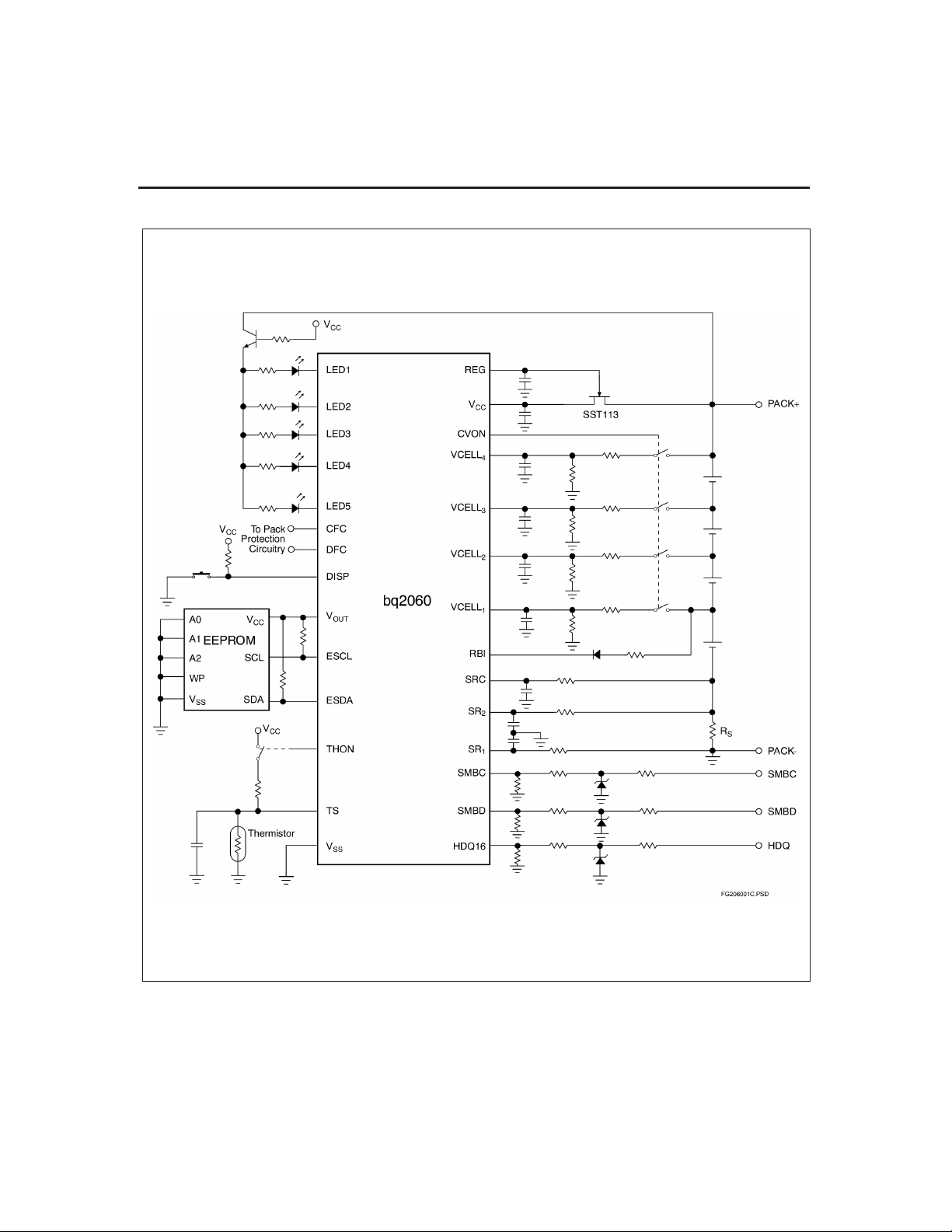
Figure 1 shows a typical bq2060A-based battery-pack
application. The circuit consists of the LED display,
voltage and temperature measurement networks,
EEPROM connections, a serial port, and the sense resis
tor. The EEPROM stores basic battery-pack configuration information and measurement-calibration values.
The EEPROM must be programmed properly for
bq2060A operation. Table 9 shows the EEPROM memory map and outlines the programmable functions available in the bq2060A.
The bq2060A accepts an NTC thermistor (Semitec
103AT) for temperature measurement. The bq2060A
uses the thermistor temperature to monitor battery-pack temperature, detect a battery full-charge con
dition, and compensate for self-discharge and charge/dis
charge battery efficiencies.
Measurements
The bq2060A uses a fully differential, dynamically bal
anced voltage-to-frequency converter (VFC) for charge
measurement and a sigma delta analog-to-digital con
verter (ADC) for battery voltage, current, and tempera
ture measurement.
Voltage, current, and temperature measurements are
made every 2–2.5 seconds, depending on the bq2060A
operating mode. Maximum times occur with compen
sated EDV, mWh mode, and maximum allowable dis
charge rate. Any AtRate computations requested or
scheduled (every 20 seconds) may add up to 0.5 seconds
to the time interval.
Charge and Discharge Counting
The VFC measures the charge and discharge flow of the
battery by monitoring a small-value sense resistor
between the SR
and SR2pins as shown in Figure 1.
1
The VFC measures bipolar signals up to 250mV. The
bq2060A detects charge activity when V
V
is positive and discharge activity when VSR=V
SR1
–V
integrates the signal over time using an internal
counter. The fundamental rate of the counter is
-
6.25µVh.
-
-
Offset Calibration
The bq2060A provides an auto-calibration feature to can
cel the voltage offset error across SR
mum charge measurement accuracy. The calibration rou
tine is initiated by issuing a command to
ManufacturerAccess(). The bq2060A is capable of auto
matic offset calibration down to 6.25µV.Offset cancellation
resolution is less than 1µV.
is negative. The bq2060A continuously
SR1
SR=VSR2
and SR2for maxi
1
Digital Filter
The bq2060A does not measure charge or discharge
counts below the digital filter threshold. The digital fil
-
ter threshold is programmed in the EEPROM and
should be set sufficiently high to prevent false signal detection with no charge or discharge flowing through the
sense resistor.
Voltage
While monitoring SR1and SR2for charge and discharge
currents, the bq2060A monitors the battery-pack potential and the individual cell voltages through the
VCELL
-
voltage and reports the result in Voltage(). The bq2060A
-
can also measure the voltage of up to four series ele
ments in a battery pack. The individual cell voltages
are stored in the optional Manufacturer Function area.
The VCELL
cells using precision resistors, as shown in Figure 1. The
maximum input for VCELL
spect to V
set so that the voltages at the inputs do not exceed the
-
1.25V limit under all operating conditions. Also, the di
vider ratios on VCELL
VCELL
the battery, the CVON output may used to connect the
-
divider to the cells only during measurement period.
-
CVON is high impedance for 250ms (12.5% duty cycle)
when the cells are measured, and driven low otherwise.
(See Table1.)
The SRC input of the bq2060A measures battery charge
and discharge current. The SRC ADC input converts
the current signal from the series sense resistor and
stores the result in Current(). The full-scale input range
to SBC is limited to ±250mV as shown in Table2.
–VCELL4pins. The bq2060Ameasures the pack
1
–VCELL4inputs are divided down from the
1
–VCELL4is 1.25V with re
. The voltage dividers for the inputs must be
SS
–VCELL4. To reduce current consumption from
3
1
–VCELL2must be half of that of
1
–
SR2
-
-
-
-
-
-
-
-
3
Page 4
bq2060A
Figure 1. Battery Pack Application Diagram–LED Display and Series Cell Monitoring
4
Page 5
bq2060A
Table 1. Example VCELL1–VCELL4Divider
and Input Range
Voltage Input
VCELL
4
VCELL
3
VCELL
2
VCELL
1
Voltage Division
Ratio
16 20.0
16 20.0
8 10.0
8 10.0
Full-Scale Input
(V)
Table 2. SRC Input Range
Sense Resistor (W) Full-Scale Input
0.02
0.03
0.05
0.10
(A)
±12.5
±8.3
±5.0
±2.5
Current
The SRC input of the bq2060A measures battery charge
and discharge current. The SRC ADC input converts
the current signal from the series sense resistor and
stores the result in Current(). The full-scale input range
to SBC is limited to ±250mV, as shown in Table 2.
Temperature
The TS input of the bq2060A in conjunction with an
NTC thermistor measures the battery temperature as
shown in Figure 1. The bq2060Areports temperature in
Temperature(). THON may be used to connect the bias
source to the thermistor when the bq2060A samples the
TS input. THON is high impedance for 60ms when the
temperature is measured, and driven low otherwise.
Gas Gauge Operation
General
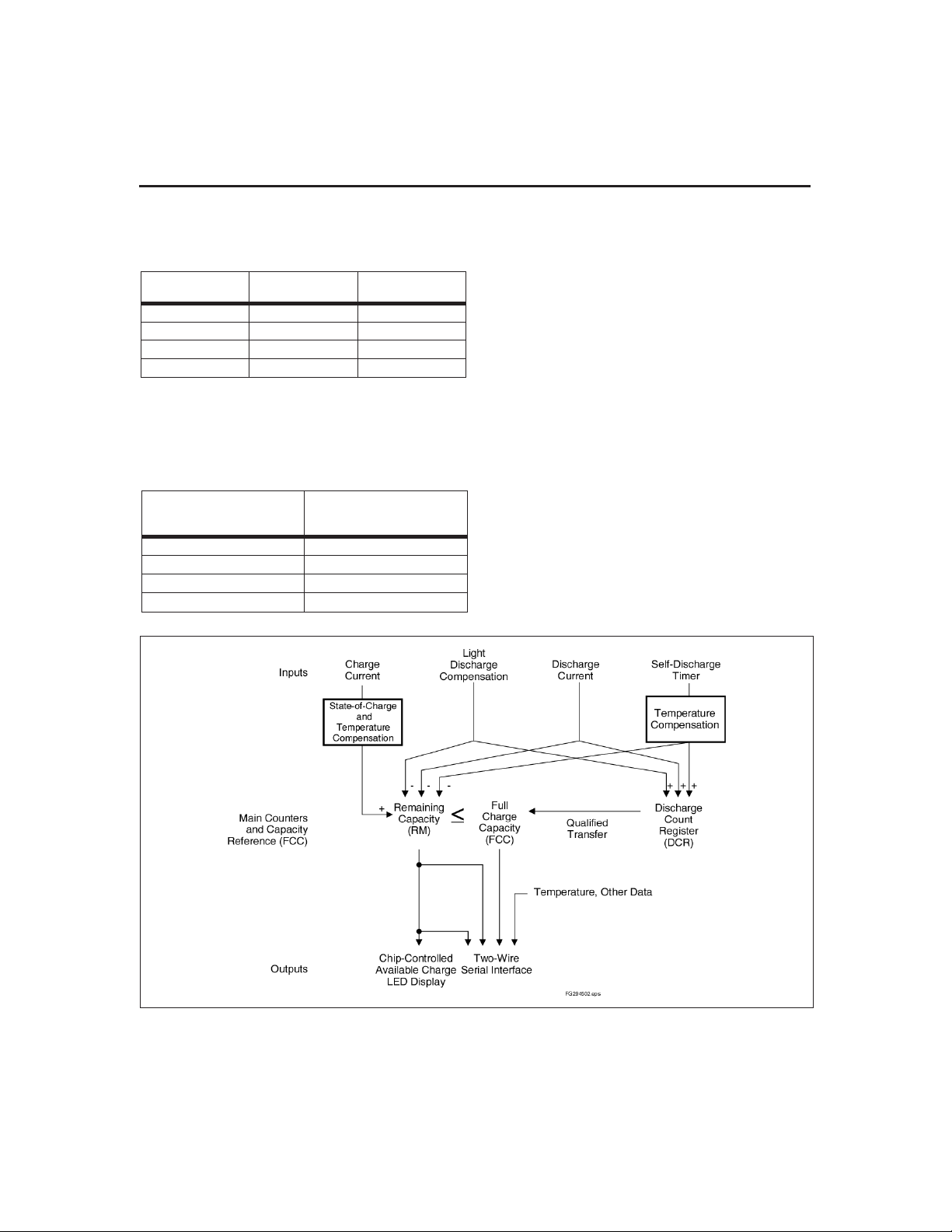
The operational overview in Figure 2 illustrates the gas
gauge operation of the bq2060A. Table 3 describes the
bq2060Aregisters.
The bq2060A accumulates a measure of charge and
discharge currents and estimates self-discharge of the
Figure 2. bq2060A Operational Overview
5
Page 6

bq2060A
Table 3. bq2060A Register Functions
Function
ManufacturerAccess 0x00 0x00 read/write n/a
RemainingCapacityAlarm 0x01 0x01 read/write mAh, 10mWh
RemainingTimeAlarm 0x02 0x02 read/write minutes
BatteryMode 0x03 0x03 read/write n/a
AtRate 0x04 0x04 read/write mA, 10mW
AtRateTimeToFull 0x05 0x05 read minutes
AtRateTimeToEmpty 0x06 0x06 read minutes
AtRateOK 0x07 0x07 read Boolean
Temperature 0x08 0x08 read 0.1°K
Voltage 0x09 0x09 read mV
Current 0x0a 0x0a read mA
AverageCurrent 0x0b 0x0b read mA
MaxError 0x0c 0x0c read percent
RelativeStateOfCharge 0x0d 0x0d read percent
AbsoluteStateOfCharge 0x0e 0x0e read percent
RemainingCapacity 0x0f 0x0f read mAh, 10mWh
FullChargeCapacity 0x10 0x10 read mAh, 10mWh
RunTimeToEmpty 0x11 0x11 read minutes
AverageTimeToEmpty 0x12 0x12 read minutes
AverageTimeToFull 0x13 0x13 read minutes
ChargingCurrent 0x14 0x14 read mA
ChargingVoltage 0x15 0x15 read mV
Battery Status 0x16 0x16 read n/a
CycleCount 0x17 0x17 read cycles
DesignCapacity 0x18 0x18 read mAh, 10mWh
DesignVoltage 0x19 0x19 read mV
SpecificationInfo 0x1a 0x1a read n/a
ManufactureDate 0x1b 0x1b read n/a
SerialNumber 0x1c 0x1c read integer
Reserved 0x1d–0x1f 0x1d - 0x1f - -
ManufacturerName 0x20 0x20–0x25 read string
DeviceName 0x21 0x28–0x2b read string
DeviceChemistry 0x22 0x30–0x32 read string
ManufacturerData 0x23 0x38–0x3b read string
Pack Status 0x2f (LSB) 0x2f (LSB) read/write n/a
Pack Configuration 0x2f (MSB) 0x2f (MSB) read/write n/a
VCELL4 0x3c 0x3c read/write mV
VCELL3 0x3d 0x3d read/write mV
VCELL2 0x3e 0x3e read/write mV
VCELL1 0x3f 0x3f read/write mV
Command Code SMBus
SMBus HDQ16
Access Units
6
Page 7

bq2060A
battery. The bq2060A compensates the charge current
measurement for temperature and state-of-charge of the
battery. It also adjusts the self-discharge estimation
based on temperature.
The main counter RemainingCapacity() (RM) represents
the available capacity or energy in the battery at any
given time. The bq2060A adjusts RM for charge,
self-discharge, and leakage compensation factors. The
information in the RM register is accessible through the
communications ports and is also represented through
the LED display.
The FullChargeCapacity() (FCC) register represents the
last measured full discharge of the battery. It is used as
the battery’s full-charge reference for relative capacity
indication. The bq2060A updates FCC when the battery
undergoes a qualified discharge from nearly full to a low
battery level. FCC is accessible through the serial com
munications ports.
The Discharge Count Register (DCR) is a non-accessible
register that only tracks discharge of the battery. The
bq2060A uses the DCR register to update the FCC regis
ter if the battery undergoes a qualified discharge from
nearly full to a low battery level. In this way, the
bq2060A learns the true discharge capacity of the battery under system use conditions.
Main Gas Gauge Registers
RemainingCapacity() (RM)
RM represents the remaining capacity in the battery.
The bq2060A computes RM in either mAh or 10mWh depending on the selected mode.
On initialization, the bq2060A sets RM to 0. RM counts
up during charge to a maximum value of FCC and down
during discharge and self-discharge to 0. In addition to
charge and self-discharge compensation, the bq2060A
calibrates RM at three low-battery-voltage thresholds,
EDV2, EDV1, and EDV0 and three programmable
midrange thresholds VOC25, VOC50, and VOC75. This
provides a voltage-based calibration to the RM counter.
DesignCapacity() (DC)
The DC is the user-specified battery full capacity. It is
calculated from Pack Capacity EE 0x3a–0x3b and is rep
resented in mAh or 10mWh. It also represents the
full-battery reference for the absolute display mode.
FullChargeCapacity() (FCC)
FCC is the last measured discharge capacity of the bat
tery. It is represented in either mAh or 10mWh depend
ing on the selected mode. On initialization, the bq2060A
sets FCC to the value stored in Last Measured Dis
charge EE 0x38–0x39. During subsequent discharges,
the bq2060A updates FCC with the last measured dis
charge capacity of the battery. The last measured dis
charge of the battery is based on the value in the DCR
register after a qualified discharge occurs. Once up
dated, the bq2060A writes the new FCC value to
EEPROM in mAh to Last Measured Discharge. FCC
represents the full battery reference for the relative dis
play mode and relative state of charge calculations.
Discharge Count Register (DCR)
The DCR register counts up during discharge, independ
ent of RM. DCR can continue to count even after RM has
counted down to 0. Prior to RM = 0, discharge activity,
light discharge estimation and self-discharge increment
DCR. After RM = 0, only discharge activity increments
DCR. The bq2060A initializes DCR to FCC – RM when
RM is within twice the programmed value in Near Full
EE 0x55. The DCR initial value of FCC – RM is reduced
-
by FCC/128 if SC = 0 (bit 2 in Control Mode) and is not
reduced if SC = 1. DCR stops counting when the battery
voltage reaches the EDV2 threshold on discharge.
Capacity Learning (FCC Update) and Qualified
-
Discharge
The bq2060A updates FCC with an amount based on the
value in DCR if a qualified discharge occurs. The new
value for FCC equals the DCR value plus the programmable nearly full and low battery levels, according to
the following equation:
FCC(new) DCR(final)
DCR(initial) measured dischar
(FCC Battery Low%+´ )
where
Battery Low % (value stored in EE 0x54)=¸256.
A qualified discharge occurs if the battery discharges
from RM ≥ FCC - Near Full*2 to the EDV2 voltage
threshold with the following conditions:
n
No valid charge activity occurs during the discharge
period. A valid charge is defined as an input of
10mAh into the battery.
n
No more than 256mAh of self-discharge and/or light
discharge estimation occurs during the discharge
period.
-
n
The temperature does not drop below 5°C during the
discharge period.
n
The battery voltage reaches the EDV2 threshold
during the discharge period and the voltage was less
than the EDV2 threshold minus 256mV when the
bq2060A detected EDV2.
-
-
n
No midrange voltage correction occurs during the
discharge period.
-
n
There is no overload condition when voltage ≤ EDV2
threshold
-
==
+ ge to EDV2
-
-
-
-
(1)
7
Page 8

bq2060A
FCC cannot be reduced by more than 256mAh or in
creased by more than 512mAh during any single update
cycle. The bq2060A saves the new FCC value to the
EEPROM within 4s of being updated.
End-of-Discharge Thresholds and Capacity Cor
rection
The bq2060A monitors the battery for three low-voltage
thresholds, EDV0, EDV1, and EDV2. The EDV thresh
olds are programmed in EDVF/EDV0 EE 0x72–0x73,
EMF/EDV1 EE 0x74–0x75, and EDV C1/C0 Fac
tor/EDV2 EE 0x78–0x79. If the CEDV bit in Pack Con
figuration is set, automatic EDV compensation is en
abled and the bq2060A computes the EDV0, EDV1, and
EDV2 thresholds based on the values in EE 0x72–0x7d,
0x06, and the battery’s current discharge rate, tempera
ture, capacity, and cycle count. The bq2060A disables
EDV detection if Current() exceeds the Overload Current
threshold programmed in EE 0x46 - EE 0x47. The
bq2060A resumes EDV threshold detection after Cur
rent() drops below the overload current threshold. Any
EDV threshold detected will be reset after 10mAh of
charge are applied.
The bq2060A uses the thresholds to apply voltage-based
corrections to the RM register according to Table4.
Table 4. State of Charge Based
on Low Battery Voltage
Threshold State of Charge in RM
EDV0 0%
EDV1 3%
EDV2 Battery Low %
The bq2060A adjusts RM as it detects each threshold. If
the voltage threshold is reached before the correspond
ing capacity on discharge, the bq2060A reduces RM to
the appropriate amount as shown in Table 4. If RM
reaches the capacity level before the voltage threshold is
reached on discharge, the bq2060A prevents RM from
decreasing until the battery voltage reaches the corre
sponding threshold, but only on a full learning-cycle dis
charge (VDQ = 1). The EDV1 threshold is ignored if Mis
cellaneous Options bit7=1.
Self-Discharge
The bq2060A estimates the self-discharge of the battery
to maintain an accurate measure of the battery capacity
during periods of inactivity. The algorithm for
self-discharge estimation takes a programmed estimate
for the expected self-discharge rate at 25°C stored in
EEPROM and makes a fixed reduction to RM of an
amount equal to RemainingCapacity()/256. The bq2060A
makes the fixed reduction at a varying time interval
that is adjusted to achieve the desired self-discharge
rate. This method maintains a constant granularity of
-
0.39% for each self-discharge adjustment, which may be
performed multiple times per day, instead of once per
day with a potentially large reduction.
The self-discharge estimation rate for 25°C is doubled
-
for each 10 degrees above 25°C or halved for each 10 de
grees below 25°C. The following table shows the relation
of the self-discharge estimation at a given temperature
-
to the rate programmed for 25°C (Y% per day):
-
-
-
Temperature ( C)
Temp < 10
10 ≤ Temp <20
-
20 ≤ Temp <30
30 ≤ Temp <40
40 ≤ Temp <50
-
50 ≤ Temp <60
60 ≤ Temp <70
70 ≤ Temp
Self-Discharge Rate
1
Y% per day
4
1
Y% per day
2
Y% per day
2Y% per day
4Y% per day
8Y% per day
16Y% per day
32Y% per day
The interval at which RM is reduced is given by the following equation, where n is the appropriate factor of 2
1
(n =
1
,
,1,2,...):
4
2
·
Self Disch e Update Time
-=
arg
640 13500
n Y per day
··
256 ( % )
The timer that keeps track of the self-discharge update
time is halted whenever charge activity is detected. The
timer is reset to zero if the bq2060A reaches the
RemainingCapacity()=FullChargeCapacity() condition
while charging.
Example: IfT=35°C (n = 2) and programmed
self-discharge rate Y is 2.5 (2.5% per day at 25°C), the
bq2060Areduces RM by RM/256 (0.39%) every
-
-
-
640 13500
·
256
··=n Y per day
(% )
6750
s
econds
This means that a 0.39% reduction of RM will be made
12.8 times per day to achieve the desired 5% per day re
duction at 35°C.
Figure 3 illustrates how the self-discharge estimate al
gorithm adjusts RemainingCapacity() vs. temperature.
Light Discharge or Suspend Current
Compensation
The bq2060A can be configured in two ways to compen
sate for small discharge currents that produce a signal
-
(2)
seconds
(3)
-
-
-
8
Page 9
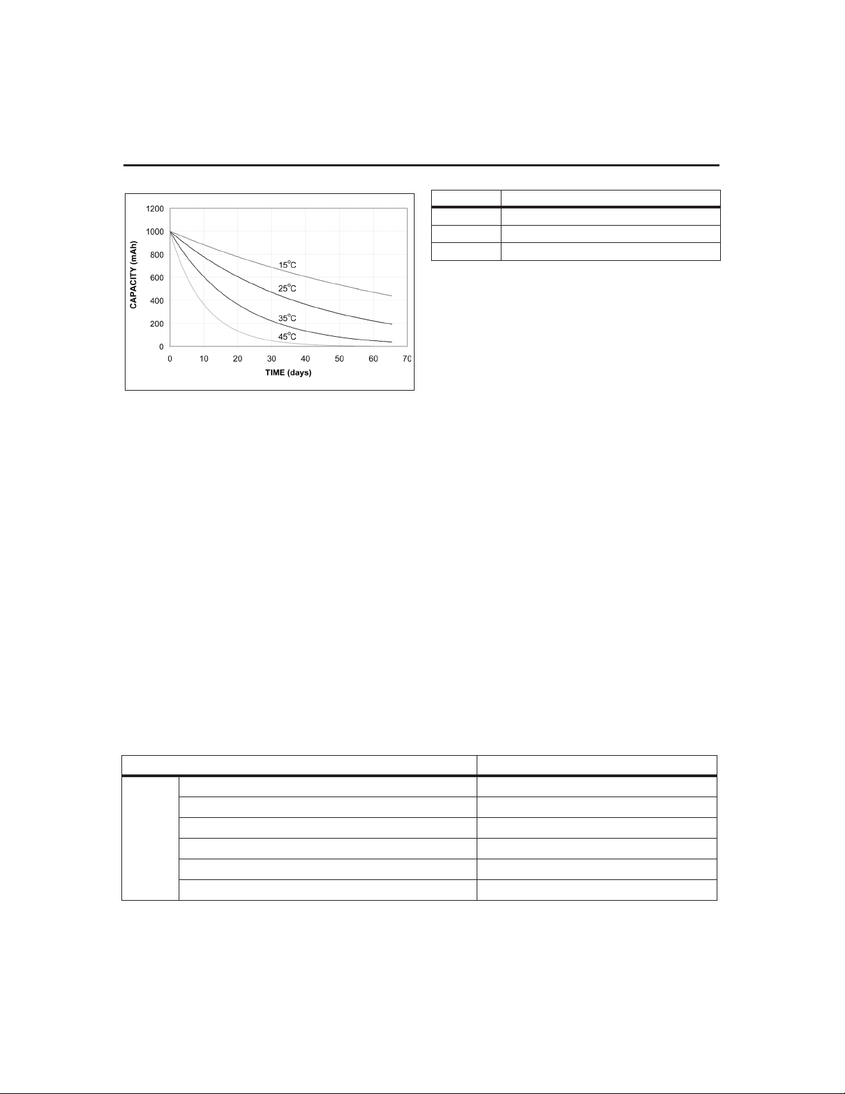
Figure 3. Self-Discharge at 2.5%/Day @25C
below the digital filter. First, the bq2060A can decrement
RM and DCR at a rate determined by the value stored in
Light Discharge Current EE 0x2b when it detects no dis
charge activity and the SMBC and SMBD lines are high.
Light Discharge Current has a range of 44µA to 11.2mA.
Alternatively, the bq2060A can be configured to disable
the digital filter for discharge when the SMBC and
SMBD lines are high. In this way, the digital filter will
not mask the leakage current signal. The bq2060A is
configured in this mode by setting the NDF bit in Con-
trol Mode.
Midrange Capacity Corrections
The bq2060A applies midrange capacity corrections
when the VCOR bit is set in Pack Configuration. The
bq2060A adjusts RM to the associated percentage at
three different voltage levels VOC25, VOC50, and
VOC75. The VOC values represent the open circuit bat
tery voltage at which RM corresponds to the associated
state of charge for each threshold.
bq2060A
Threshold Associated State of Charge
VOC25 25%
VOC50 50%
VOC75 75%
For the midrange corrections to occur, the temperature
must be in the range of 19°Cto31°C inclusive and the
Current() and AverageCurrent() must both be between
–64mA and 0. For a correction to occur, the bq2060A
must also detect the need for correction during two adja
cent measurements separated by 20s. The second mea
surement is not required if the first measurement is im
mediately after a device reset. The bq2060A makes
midrange corrections as shown in Table5.
Charge Control
Charging Voltageand CurrentBroadcasts
-
The bq2060A supports SBS charge control by broadcasting
the ChargingCurrent() and ChargingVoltage() to the
Smart Charger address. The bq2060A broadcasts the requests every 10s. The bq2060A updates the values used
in the charging current and voltage broadcasts based on
the battery’s state of charge, voltage, and temperature.
The fast-charge rate is programmed in Fast-Charging
Current EE 0x1a - 0x1b while the charge voltage is programmed in Charging VoltageEE 0x0a-0x0b.
The bq2060A internal charge control is compatible with
popular rechargeable chemistries. The primary
charge-termination techniques include a change in temperature over a change in time (∆T/∆t) and current
taper, for nickel-based and Li-Ion chemistries, respec
tively. The bq2060A also provides pre-charge qualifica
tion and a number of safety charge suspensions based
on current, voltage, temperature, and state of charge.
-
-
-
-
-
-
Voltage()
Table 5. Midrange Corrections
Condition Result
≥ VOC75 and RelativeStateOfCharge() ≤ 63% RelativeStateOfCharge()→75%
< VOC75 and RelativeStateOfCharge() ≥ 87% RelativeStateOfCharge()→75%
≥VOC50 and RelativeStateOfCharge() ≤ 38% RelativeStateOfCharge()→50%
<VOC50 and RelativeStateOfCharge() ≥ 62% RelativeStateOfCharge()→50%
≥ VOC25 and RelativeStateOfCharge() ≤ 13% RelativeStateOfCharge()→25%
< VOC25 and RelativeStateOfCharge() ≥ 37% RelativeStateOfCharge()→25%
9
Page 10

bq2060A
Alarm Broadcasts to SmartCharger andHost
If any of the bits 8–15 in BatteryStatus() is set, the
bq2060A broadcasts an AlarmWarning() message to the
Host address. If any of the bits 12–15 in BatteryStatus() is
set, the bq2060A also sends an AlarmWarning() message
to the Smart Charger address. The bq2060A repeats the
AlarmWarning() message every 10s until the bits are
cleared.
Pre-Charge Qualification
The bq2060A sets ChargingCurrent() to the pre-charge
rate as programmed in Pre-Charge Current EE
0x1e-0x1f under the following conditions:
Voltage: The bq2060A requests the pre-charge
n
charge rate when Voltage() drops below the EDV0
threshold (compensated or fixed EDVs). Once
requested, a pre-charge rate remains until Voltage()
increases above the EDVF threshold. The bq2060A
also broadcasts the pre-charge value immediately
after a device reset until Voltage() is above the EDVF
threshold. This threshold is programmed in
EDVF/EDV0 EE 0x72-0x73.
Temperature: The bq2060A requests the
n
pre-charge rate when Temperature() is between 0°C
and 5°C. Temperature() must rise above 5°C before
the bq2060A requests the fast-charge rate.
Charge Suspension
The bq2060A may temporarily suspend charge if it detects a charging fault. A charging fault includes the following conditions.
n
Overcurrent: An overcurrent condition exists when
the bq2060A measures the charge current to be more
than the Overcurrent Margin above the
ChargingCurrent(). Overcurrent Margin is programmed
in EE 0x49. On detecting an overcurrent condition, the
bq2060A sets the ChargingCurrent() to zero and sets the
TERMINATE_CHARGE_ALARM bit in Battery
Status(). The overcurrent condition and TERMINATE_
CHARGE_ALARM are cleared when the measured
current drops below the ChargingCurrent plus the
Overcurrent Margin.
n
Overvoltage: An overvoltage condition exists when the
bq2060A measures the battery voltage to be more than
the Overvoltage Margin above the ChargingVoltage() or
a Li-Ion cell voltage has exceeded the overvoltage limit
programmed in Cell Under-/Overoltage. Overvoltage
Margin is programmed in EE 0x48 and Cell Under/Over
Voltage in EE 0x4a (least significant nibble). On
detecting an overvoltage condition, the bq2060A sets the
ChargingCurrent() to zero and sets the
TERMINATE_CHARGE_ALARM bit in BatteryStatus().
The bq2060A clears the TERMINATE_
CHARGE_ALARM bit when it detects that the battery
is no longer being charged (DISCHARGING bit set in
BatteryStatus()). The bq2060A continues to broadcast
zero charging current until the overvoltage condition is
cleared. The overvoltage condition is cleared when the
measured battery voltage drops below the
ChargingVoltage() plus the Overvoltage Margin or when
the CVOV bit is reset.
Over-Temperature: An over-temperature condition
n
exists when Temperature() is greater than or equal to
the Max T value programmed in EE 0x45 (most
significant nibble). On detecting an over-temperature
condition, the bq2060A sets the ChargingCurrent() to
zero and sets the OVER_TEMP_ALARM and
TERMINATE_CHARGE_ ALARM bit in
BatteryStatus() and the CVOV bit in Pack Status.
The over-temperature condition is cleared when
Temperature() is equal to or below (Max T –5°C).
The temperature set by MaxT is increased by 16°Cif
bit5inMiscellaneous Options is set.
Overcharge: An overcharge condition exists if the
n
battery is charged more than the Maxmum
Overcharge value after RM = FCC. Maximum
Overcharge is programmed in EE 0x2e–0x2f. On
detecting an overcharge condition, the bq2060A sets
the ChargingCurrent() to zero and sets the
OVER_CHARGED_ALARM, TERMINATE_CHARGE_
ALARM, and FULLY_CHARGED bits in
BatteryStatus(). The bq2060A clears the OVER_
CHARGED_ALARM and TERMINATE_CHARGE_
ALARM when it detects that the battery is no longer
being charged. The FULLY_CHARGED bit remains set
and the bq2060A continues to broadcast zero charging
current until RelativeStateOfCharge() is less than
Fully Charged Clear% programmed in EE 0x4c.The
counter used to track overcharge capacity is reset
with 2mAh of discharge.
n
Under-Temperature: An under-temperature
condition exists if Temperature() < 0°C. On detecting
an under temperature condition, the bq2060A sets
ChargingCurrent() to zero. The bq2060A sets
ChargingCurrent() to the appropriate pre-charge rate
or fast-charge rate when Temperature() ≥ 0°C.
Primary Charge Termination
The bq2060A terminates charge if it detects a
charge-termination condition. A charge-termination
condition includes the following.
n
∆T/∆t: For ∆T/∆t, the bq2060A detects a change in
temperature over many seconds. The ∆T/∆t setting
is programmable in both the temperature step,
DeltaT (1.6°C - 4.6°C), and the time step, DeltaT
Time (20s-320s). Typical settings for 1°C/minute
include 2°C/120s and 3°C/180s. Longer times are
required for increased slope resolution. The DeltaT
value is programmed in EE 0x45 (least significant
nibble) and the Delta T Time in EE 0x4e.
10
Page 11

bq2060A
In addition to the ∆T/∆t timer, a hold-off timer starts
when the battery is being charged at more than
255mA and the temperature is above 25°C. Until this
timer expires, ∆T/∆t detection is suspended. If
Current() drops below 256mA or Temperature() below
25°C, the hold-off timer resets and restarts only when
the current and temperature conditions are met again.
The hold-off timer is programmable (20s – 320s) with
Holdoff Time value in EE 0x4f.
Current Taper: For current taper, ChargingVoltage()
n
must be set to the pack voltage desired during the
constant-voltage phase of charging. The bq2060A detects
a current taper termination when the pack voltage is
greater than the voltage determined by Current Taper
Qual Voltage in EE 0x4f and the charging current is
below a threshold determined by Current Taper
Threshold in EE 0x4e, for at least 80s. The bq2060A uses
the VFC to measure current for current taper
termination. The current must also remain above
0.5625/R
Once the bq2060A detects a primary charge termination,
it sets the TERMINATE_CHARGE_ALARM and
FULLY_CHARGED bits in BatteryStatus(), and sets
the ChargingCurrent() to the maintenance charge rate
as programmed in Maintenance Charging Current EE
0x1c–0x1d. On termination, the bq2060A also sets RM
to a programmed percentage of FCC, provided that
RelativeStateOfCharge() is below the desired
percentage of FCC and the CSYNC bit in Pack Configu-
ration EE 0x3f is set. If the CSYNC bit is not set and
RelativeStateOfCharge() is less than the programmed
percentage of FCC, the bq2060A clears the
FULLY_CHARGED bit in BatteryStatus(). The programmed percentage of FCC, Fast Charge Termination
%, is set in EE 0x4b. The bq2060A clears the
FULLY_CHARGED bit when RelativeStateOfCharge()
is less than the programmed Fully Charged Clear %.
The bq2060A broadcasts the fast-charge rate when the
FULLY_CHARGED bit is cleared and voltage and tem
perature permit. The bq2060A clears the TERMI
NATE_CHARGE_ALARM when it no longer detects
that the battery is being charged or it no longer detects
the termination condition. See Table 6 for a summary
of BatteryStatus() alarm and status bit operation.
mA to qualify the termination condition.
S
Display Port
General
The display port drives a 4 or 5 LED bar-graph display.
The display is activated by a logic signal on the DISP
put. The bq2060A can display RM in either a relative or
absolute mode with each LED representing a percentage
of the full-battery reference. In relative mode, the
bq2060A uses FCC as the full-battery reference; in abso
lute mode, it uses DC.
The DMODE bit in Pack Configuration programs the
bq2060A for the absolute or relative display mode. The
in
LED bit in Control Mode programs the 4 or 5 LED op
tion. A 5th LED can be used with the 4 LED display op
tion to show when the battery capacity is ≥to 100%.
Activation
The display may be activated at any time by a
high-to-low transition on the DISP
accomplished with a pullup resistor and a pushbutton
switch. Detection of the transition activates the dis
and starts a four-second display timer. The timer
play
expires and turns off the display whether
brought low momentarily or held low indefinitely. Reac
tivation of the display requires that the DISP
turn to a logic-high state and then transition low again.
The second high-to-low transition must occur after the
display timer expires. The bq2060A requires the DISP
input to remain stable for a minimum of 250ms to detect
the logic state.
If the EDV0 bit is set, the bq2060A disables the LED
display. The display is also disabled during a VFC cali
bration and should be turned off before entering
low-power storage mode.
input. This is usually
DISP
Display Modes
In relative mode, each LED output represents 20% or
25% of the RelativeStateOfCharge() value. In absolute
mode, each LED output represents 20% or 25% of the
AbsoluteStateOfCharge() value. Tables 7A and 7B show
the display operation.
In either mode, the bq2060A blinks the LED display if
RemainingCapacity() is less than Remaining
CapacityAlarm(). The display is disabled if EDV0= 1.
Secondary Protection for Li-Ion
The bq2060A has two pins, CFC and DFC, that can be
used for secondary override control of a Li-Ion protector
or for blowing a fuse to disable the battery pack. The
CFC pin is the Charge FET Control pin for secondary
protector control or for blowing a fuse. The DFC pin is
the Discharge FET Control pin for secondary protector
control. Discharge current can cause an override of the
CFC control, and charge current can cause an override
of the DFC control. Pack Status can read the CVOV
and CVUV status flags and can also read the true logic
state of theCFC and DFC pins.
-
The CVOV status flag is set if Voltage() ≥ Charging
Voltage() + Overvoltage Margin, any VCELL voltage ≥
Cell Overvoltage threshold, or if Temperature() ≥ MaxT.
When CVOV=1 and Miscellaneous Options bit6=0,the
CFC pin is pulled low unless DISCHARGING bit in
BatteryStatus() is set or Temperature() > Safety
Overtemperature threshold. If Miscellaneous Options bit
6 = 1, the CPC pin is pulled low only if Temperature()
>Safety Overtemperature threshold.
was
input re
-
-
-
-
-
-
11
Page 12

bq2060A
Table 6. Alarm and Status Bit Summary
Battery State Conditions
Overcurrent
Overvoltage
Overtemperature
Overcharge
Undertemperature
Fast charge
termination
Fully discharged
Overdischarged
Low capacity RM() < RCA() RCA = 1
Low run-time ATTE() < RTA() RTA= 1
C() ≥ CC() + Overcurrent
Margin
V() ≥ CV() + Overvoltage
Margin
VCELL1, 2, 3, or 4 > Cell
Over Voltage
T() ≥ Max T
Capacity added after
RM() = FCC() ≥
Maximum Overcharge
T()<0°C
∆T/∆t or Current Taper
V() ≤ EDV2
or
RM() < FCC()*Battery
Low%
V() ≤ EDV0
VCELL1, 2, 3 or 4 < Cell
Under Voltage
RM() = 0 TDA = 1
CC() State and
BatteryStatus Bits Set
CC() = 0, TCA = 1 C() < CC() + Overcurrent Margin
CC()=0,CVOV=1
CC()=0,OTA=1,
TCA = 1, CVOV = 1
CC() = 0, FC = 1 RSOC() < Fully Charged Cleared %
OCA = 1, TCA= 1 DISCHARGING = 1
CC() = Maintenance
Charging Current,
TDA = 1, CVUV = 1
CC() = Fast or Pre-charge Current
and/or Bits Cleared
TCA = 1 DISCHARGING = 1
V() < CV() + Overvoltage Margin
Li-Ion cell voltage ≤ Cell Over Voltage
T() ≤ Max T -5°CorT()≤ 43°C
CC() = 0
FC=1
TCA = 1
FD = 1 RSOC() > 20%
TDA = 1 V() > EDV0
0°C ≤ Τ() < 5°C, CC() = Pre-Charge
Current
T() ≥5°C, CC() = Fast-Charging Current
RSOC() < Fully Charged Cleared %
DISCHARGING=1ortermination
condition is no longer valid.
VCELL1, 2, 3, or 4 ≥ Cell Under Voltage
RM() > 0
RM() ≥ RCA()
ATTE() ≥ RTA()
Note: C() = Current(), CV() = ChargingVoltage(), CC() = ChargingCurrent(), V() = Voltage(), T() = Tempera
ture(), TCA = TERMINATE_CHARGE_ALARM,OTA = OVER_TEMPERATURE_ALARM,
OCA = OVER_CHARGED_ALARM, TDA= TERMINATE_DISCHARGE_ALARM, FC =
FULLY_CHARGED,
FD = FULLY_DISCHARGED, RSOC() = RelativeStateOfCharge(). RM() = RemainingCapacity(),
RCA = REMAINING_CAPACITY_ALARM, RTA= REMAINING_TIME_ALARM,
ATTE() = AverageTimeToEmpty(), RTA() = RemainingTimeAlarm(), RCA() = RemainingCapacityAlarm(),
FCC() = FullChargeCapacity.
12
-
Page 13

bq2060A
Table 7A. Display Mode
Condition
Relative or
Absolute
StateOfCharge()
EDV0 = 1 OFF OFF OFF OFF OFF
<20%
≥20%, <40%
≥40%, <60%
≥60%, <80%
≥80%
The CVUV status flag is set if any VCELL voltage < Cell
Undervoltage threshold. When CVUV = 1, the DVC pin
is pulled low unless DISCHARGING bit in
BatteryStatus() is set or Temperature() is not set.
Cell Undervoltage and Cell Overvoltage limits may be
programmed in the upper and lower nibbles of EE 0x4a.
Safety Overtemperature threshold may be programmed
in EE 0x09, and Miscellaneous Options is programmed
in EE 0x08.
5 LED Display Option
LED1 LED2 LED3 LED4 LED5
ON OFF OFF OFF OFF
ON ON OFF OFF OFF
ON ON ON OFF OFF
ON ON ON ON OFF
ON ON ON ON ON
Low-Power Storage Mode
The bq2060A enters low-power mode 5– 8s after receiving the Enable Low-Power command. In this mode the
bq2060A consumes less than 10µA. A rising edge on
SMBC, SMBD, or HDQ16 restores the bq2060A to the
full operating mode. The bq2060A does not perform any
gas gauge functions during low-power storage mode.
Device Reset
The bq2060A can be reset when power is applied or by
commands over the HDQ16 or SMBus. Upon reset, the
bq2060A initializes its internal registers with the infor
mation contained in the configuration EEPROM. The
following command sequence initiates a full bq2060A re
set:
Write 0xff5a to address 0x4f
Write 0x0000 to address 0x7d
Write 0x0080 to address 0x7d
A partial reset of the bq2060A occurs if step 1 is omitted
and all check-byte values previously loaded into RAM
are still correct. All initial RAM values are read from
EEPROM for both full and partial resets. A full reset
initializes MaxError = 100%, sets RELEARN_FLAG (bit
7)=1inBattery Mode, and initializes RM from EE
0x2c–2d (should be zero for rechargeable batteries). A
Table 7B. Display Mode
Condition
Relative or
Absolute
StateOfCharge()
EDV0 = 1 OFF OFF OFF OFF
<25%
≥25%, <50%
≥50%, <75%
≥75%
partial reset leaves MaxError, RELEARN_FLAG, and
RM unchanged. The bq2060A delays reading the
EEPROM for 700ms after all resets to allow settling
time for V
CC
.
4 LED Display Option
LED1 LED2 LED3 LED4
ON OFF OFF OFF
ON ON OFF OFF
ON ON ON OFF
ON ON ON ON
Communication
The bq2060A includes two types of communication
ports: SMBus and HDQ16. The SMBus interface is a
2-wire bidirectional protocol using the SMBC (clock) and
SMBD (data) pins. The HDQ16 interface is a 1-wire
bidirectional protocol using the HDQ16 pin. All three
communication lines are isolated from V
pulled-up higher than V
pull these lines low if V
should be pulled down with a 100KΩ resistor if not
used.
The communication ports allow a host controller, an
SMBus compatible device, or other processor to access
the memory registers of the bq2060A. In this way a sys
tem can efficiently monitor and manage the battery.
-
SMBus
The SMBus interface is a command-based protocol. A
processor acting as the bus master initiates communica
tion to the bq2060A by generating a START condition. A
START condition consists of a high-to-low transition of
the SMBD line while the SMBC is high. The processor
then sends the bq2060A device address of 0001011 (bits
7–1) plus a R/W
mand code. The R/W
the bq2060A to either store the forthcoming data to a
register specified by the SMBus command code or out
put the data from the specified register. The processor
completes the access with a STOP condition. A STOP
condition consists of a low-to-high transition of the
SMBD line while the SMBC is high. With SMBus, the
most significant bit ofa data byte is transmitted first.
bit (bit 0) followed by an SMBus com
. Also, the bq2060A will not
CC
to the part is zero . HDQ16
CC
bit and the command code instruct
and may be
CC
-
-
-
-
13
Page 14

bq2060A
In some instances, the bq2060A acts as the bus master.
This occurs when the bq2060A broadcasts charging re
quirements and alarm conditions to device addresses
0x12 (SBS Smart Charger) and 0x10 (SBS Host Control
ler.)
SMBus Protocol
The bq2060Asupports the following SMBus protocols:
Read Word
n
Write Word
n
Read Block
n
A processor acting as the bus master uses the three pro
tocols to communicate with the bq2060A. The bq2060A
acting as the bus master uses the WriteWordprotocol.
The SMBD and SMBC pins are open drain and require
external pullup resistors.
SMBus Packet Error Checking
The bq2060A supports Packet Error Checking as a mechanism to confirm proper communication between it and
another SMBus device. Packet Error Checking requires
that both the transmitter and receiver calculate a Packet
Error Code (PEC) for each communication message. The
device that supplies the last byte in the communication
message appends the PEC to the message. The receiver
compares the transmitted PEC to its PEC result to determine if there is a communication error.
PEC Protocol
The bq2060A can receive or transmit data with or with
out PEC. Figure 4 shows the communication protocol
for the Read Word, Write Word, and Read Block mes
sages without PEC. Figure 5 includes PEC.
In the Write Word protocol, the bq2060A receives the
PEC after the last byte of data from the host. If the host
does not support PEC, the last byte of data is followed
by a STOP condition. After receipt of the PEC, the
bq2060A compares the value to its calculation. If the
PEC is correct, the bq2060A responds with an AC
KNOWLEDGE. If it is not correct, the bq2060A re
sponds with a NOT ACKNOWLEDGE and sets an error
code.
In the Read Word and Block Read, the host generates an
ACKNOWLEDGE after the last byte of data sent by the
bq2060A. The bq2060A then sends the PEC and the
host acting as a master-receiver generates a NOT AC
KNOWLEDGE and a STOPcondition.
PEC Calculation
The basis of the PEC calculation is an 8-bit Cyclic Re
dundancy Check (CRC-8) based on the polynomial C(X)
8+X2+X1
=X
-
bytes in the transmission, including address, command,
and data. The PEC calculation does not include AC
-
KNOWLEDGE, NOT ACKNOWLEDGE, START, STOP,
+ 1. The PEC calculation includes all
and Repeated START bits.
For example, the host requests RemainingCapacity()
from the bq2060A. This includes the host following the
Read Word protocol. The bq2060A calculates the PEC
based on the following 5 bytes of data, assuming the re
maining capacity of the battery is 1001mAh.
Battery Address with R/W = 0: 0x16
n
Command Code for RemainingCapacity(): 0x0f
n
Battery Address with R/W = 1: 0x17
n
-
RemainingCapacity(): 0x03e9
n
For 0x160f17e903, the bq2060A transmits a PEC of 0xe8
to the host.
PEC Enable in Master Mode
PEC for master mode broadcasts to the charger, host, or
both can be enabled/disabled with the combination of
the bits HPE and CPE in Control Mode.
SMBus On and Off State
The bq2060A detects whether the SMBus enters the Off
State” by monitoring the SMBC and SMBD lines. When
both signals are continually low for at least 2.5s, the
bq2060A detects the Off State. When the SMBC and
SMBD lines go high, the bq2060A detects the On State
and can begin communication within 1ms. One-MΩ
pulldown resistors on SMBC and SMBD are recom
mended for reliable Off State detection.
-
HDQ16
The HDQ16 interface is a command-based protocol. (See
Figure 6.) A processor sends the command code to the
bq2060A. The 8-bit command code consists of two fields,
the 7-bit HDQ16 command code (bits 0–6) and the 1-bit
R
/W field. The R/W field directs the bq2060Aeither to
n
Store the next 16 bits of data to a specified register or
-
n
Output 16 bits of data from the specified register
With HDQ16, the least significant bit of a data byte
(command) or word (data) is transmitted first.
A bit transmission consists of three distinct sections. The
first section starts the transmission by either the host or
the bq2060A taking the HDQ16 pin to a logic-low state
-
for a period t
data-transmission, where the data bit is valid by the
time, t
nication. The data bit is held for a period t
the host processor or bq2060Ato sample the data bit.
-
after the negative edge used to start commu
DSU;B
. The next section is the actual
STRH;B
DH;DV
-
-
-
-
to allow
14
Page 15

Figure 4. SMBus Communication Protocol without PEC
bq2060A
Figure 5. SMBus Communication Protocol with PEC
15
Page 16

bq2060A
The final section is used to stop the transmission by re
turning the HDQ16 pin to a logic-high state by at least
the time t
communication. The final logic-high state should be un
til a period t
transmission was stopped properly.
If a communication error occurs (e.g., t
host sends the bq2060A a BREAK to reinitiate the serial
after the negative edge used to start
SSU;B
to allow time to ensure that the bit
CYCH;B
CYCB
> 250µs), the
interface. The bq2060A detects a BREAK when the
HDQ16 pin is in a logic-low state for a time t
greater. The HDQ16 pin is then returned to its normal
ready-high logic state for a time t
then ready to receive a command from the host proces
. The bq2060A is
BR
or
B
sor.
The HDQ16 pin is open drain and requires an external
pullup resistor.
Command Codes
The SMBus Command Codes are in ( ), the HDQ16 in [ ].
T emperature(), Voltage(), Current(), and AverageCurrent(),
performance specifications are at regulated V
and a temperature of 0–70°C.
ManufacturerAccess() (0x00); [0x00–0x01]
Description:
This function provides writable command codes to control the bq2060A during normal operation and pack
manufacture. These commands can be ignored if sent
within one second after a device reset. The following list
of commands are available.
0x0618 Enable Low-Power Storage Mode: Activates
the low-power storage mode. The bq2060A enters the
storage mode after a 5–8s delay. The bq2060A accepts
other commands to ManufacturerAccess() during the
delay before entering low-power storage mode. The
CC(VRO
LEDs must be off before entering the low-power storage
mode as the display state remains unchanged.
-
The bq2060Aclears the ManufacturerAccess() command
within 900ms of acknowledging the Enable Low-Power
Storage command. The VFC Calibration command may
be sent 900–5000ms after SMBus acknowledgment of
the Enable Low-Power Storage command. In this case,
the bq2060A delays entering storage mode until the cali
bration process completes and the bq2060A stores the
new calibration values in EEPROM.
0x062b SEAL: Instructs the bq2060A to restrict access
-
to those functions listed in Table 3. The bq2060A com
pletes the seal function and clears ManufacturerAccess()
within 900ms of acknowledging the command.
0x064d Charge Synchronization: Instructs the
bq2060A to update RM to a percentage of FCC as
defined in Fast Charge Termination %. The bq2060A
updates RM and clears ManufacturerAccess() within
900ms of acknowledging the command.
)
0x0653 Enable VFC Calibration: Instructs the unsealed bq2060A to begin VFC calibration. With this
command the bq2060A deselects the SR
and SR2 inputs
1
and calibrates for IC offset only. It is best to avoid
charge or discharge currents through the sense resistor
during this calibration process.
0x067e Alternate VFC Calibration: Instructs the
unsealed bq2060A to begin VFC calibration. With this
command, the bq2060A does not deselect the SR
SR
inputs and does calibrate for IC and PCB offset.
2
During this procedure no charge or discharge currents
During VFC calibration, the bq2060A disables the LED
display and accepts only the Stop VFC Calibration and
-
-
and
1
Figure 6. HDQ16 Communication Example
16
Page 17

bq2060A
the SEAL commands to ManufacturerAccess(). The
bq2060A disregards all other commands. SMBus
communication should be kept to a minimum during
VFC calibration to reduce the noise level and allow a
more accurate calibration.
Once started, the VFC calibration procedure completes
automatically. When complete, the bq2060A saves the
calibration values in EEPROM. The calibration nor
mally takes about 8 to 10 minutes. The calibration time
is inversely proportional to the bq2060A VFC (and PCB)
offset error. The bq2060A caps the calibration time at
one hour in the event of calibrating zero offset error. The
VFC calibration can be done as the last step in a battery
pack test procedure since the calibration can complete
automatically after removal from a test setup.
The bq2060A clears ManufacturerAccess() within 900ms
and starts calibration within 3.2s of acknowledging the
command.
0x0660 Stop VFC Calibration: Instructs the bq2060A
to abort a VFC calibration procedure. If aborted, the
bq2060A disables offset correction. The bq2060A stops
calibration within 20ms of acknowledging the command.
0x0606 Program EEPROM: Instructs the unsealed
bq2060A to connect the SMBus to the EEPROM I
2
C bus.
The bq2060A applies power to the EEPROM within
900ms of acknowledging the command. After issuing the
program EEPROM command, the bq2060A monitoring
functions are disabled until the I
The bq2060A disconnects the I
the Battery Address 0x16 is sent over the SMBus. The
Battery Address 0x16 to disconnect the I
2
C bus is disconnected.
2
C bus when it detects that
2
C bus should
not be sent until 10ms after the last write to the
EEPROM.
Example: The following sequence of actions is an exam
ple of how to use the ManufacturerAccess() commands
in an efficient manner to take a battery pack that has
completed all testing and calibration except for VFC cal
ibration and to make it ready for shipment in the
SEALED state and in low-power storage mode:
1. Complete testing and calibration with desired final
values stored in EEPROM. This process includes
setting the SEAL bit in Pack Configuration.
Sending a reset command to the bq2060A during
test ensures that RAM values correspond to the fi
nal EEPROM values
2. If the initial value of RemainingCapacity() must be
non-zero, the desired value may be written to Com
mand 0x26 with the pack unsealed. A reset sent af
ter this step resetsRM to zero.
3. Issue the Enable Low-Power Storage Mode com
mand.
4. Within 900–1600ms after sending the Enable
Low-Power command, issue the Enable VFC Cali
bration command. This delays the low-power
storage mode until after VFC calibration comple
tion.
5. Issue the SEAL Command subsequent to the VFC
Calibration command. The bq2060A must receive
the SEAL Command before VFC calibration com
pletes. The bq2060A resets the OCE bit in Pack
-
Status when calibration begins and sets the bit
when calibration successfully completes.
After VFC calibration completes automatically, the
bq2060A saves the VFC offset cancellation values in
EEPROM and enters the low-power storage mode in
about 20s. In addition, the bq2060A is sealed, allowing
access as defined in Table3 only.
Purpose:
The ManufacturerAccess() function provides the system
host access to bq2060A functions that are not defined by
the SBD.
SMBus Protocol: Reador WriteWord
Input/Output: Word
RemainingCapacityAlarm() (0x01); [0x01]
Description:
Sets or gets the low-capacity threshold value. Whenever
the RemainingCapacity() falls below the low capacity
value, the bq2060A sends AlarmWarning() messages to
the SMBus Host with the REMAINING_CAPACITY_ALARM bit set. A low-capacity value of 0 disables
this alarm. The bq2060A initially sets the low-capacity
value to Remaining Capacity Alarm value programmed
in EE 0x04 - 0x05. The low-capacity value remains unchanged until altered by the RemainingCapacityAlarm() function. The low-capacity value may
be expressed in either current (mA) or power (10mWh)
depending on the setting of the BatteryMode()’s CAPAC
ITY_MODE bit.
-
Purpose:
The RemainingCapacityAlarm() function can be used by
systems that know how much power they require to
save their operating state. It enables those systems to
more finely control the point at which they transition
into suspend or hibernate state. The low-capacity value
can be read to verify the value in use by the bq2060’s
-
low capacity alarm.
SMBus Protocol: Read or WriteWord
-
Input/Output: Unsigned integer—value below which
-
Low Capacity messages are sent.
-
-
-
-
-
17
Page 18

bq2060A
Battery Modes
CAPACITY_MODE
bit=0
Units mAh @ C/5 10mWh @ P/5
Range 0–65,535mAh 0–65,535 10mWh
Granularity Not applicable
Accuracy See RemainingCapacity()
RemainingTimeAlarm() (0x02); [0x02]
Description:
Sets or gets the remaining time alarm value. Whenever the
AverageTimeToEmpty() falls below the remaining time
value, the bq2060A sends AlarmWarning() messages to the
SMBus Host with the REMAINING_TIME_ALARM bit set.
A remaining time value of 0 effectively disables this alarm.
The bq2060A initially sets the remaining time value to the
Remaining Time Alarm value programmed in EE 0x02 0x03. The remaining time value remains unchanged until
altered by the RemainingTimeAlarm()function.
Purpose:
The RemainingTimeAlarm() function can be used by systems that want to adjust when the remaining time
alarm warning is sent. The remaining time value can be
read to verify the value in use by the bq2060’s
RemainingTimeAlarm().
SMBus Protocol: Read or WriteWord
Input/Output:
Unsigned integer—the point below which remain
ing time messages are sent.
Units: minutes
Range: 0to 65,535 minutes
Granularity: Notapplicable
Accuracy: seeAverageTimeToEmpty()
BatteryMode() (0x03); [0x03]
Description:
This function selects the various battery operational
modes and reports the battery’smode and requests.
Defined modes include
n
Whether the battery’s capacity information is
specified in mAh or 10mWh (CAPACITY_MODE bit)
n
Whether the ChargingCurrent() and ChargingVoltage()
values are broadcast to the Smart Battery Charger
when the bq2060A detects the battery requires charging
(CHARGER_MODE bit)
CAPACITY_MODE
bit=1
Whether all broadcasts to the Smart Battery Charger
n
and Host are disabled
The defined request condition is the battery requesting
a conditioning cycle (RELEARN_FLAG).
Purpose:
The CAPACITY_MODE bit allows power management
systems to best match their electrical characteristics
with those reported by the battery. For example, a
switching power supply represents a constant power
load, whereas a linear supply is better represented by a
constant current model. The CHARGER_MODE bit al
lows a SMBus Host or Smart Battery Charger to over
ride the Smart Battery’s desired charging parameters by
disabling the bq2060’s broadcasts. The RE
LEARN_FLAG bit allows the bq2060A to request a con
ditioning cycle.
SMBus Protocol: Read or WriteWord
Input/Output:
Unsigned integer —bit mapped— see below.
Units: notapplicable
Range: 0–1
Granularity: notapplicable
Accuracy: notapplicable
The BatteryMode() word is divided into two halves, the
most significant bit (bits 8–15), which is read/write and
the least significant bit (bits 0–7), which is read only.
The bq2060A forces bits 0–6 to zero and prohibits writes
-
to bit 7.
Table 8 summarizes the meanings of the individual bits
in the BatteryMode() word and specifies the default val
ues, where applicable, are noted.
INTERNAL_CHARGE_CONTROLLER bit is not
used by the bq2060A.
PRIMARY_BATTERY_SUPPORT bit is not used by
the bq2060A.
RELEARN_FLAG bit set indicates that the bq2060A is
requesting a capacity relearn cycle for the battery. The
bq2060A sets the RELEARN_FLAG under any of three
conditions: full reset, detection of 20 cycle counts with
out an FCC update, or a midrange voltage correction.
The bq2060A clears this flag after a learning cycle has
been completed.
CHARGE_CONTROLLER_ENABLED bit is not used
by the bq2060A. The bq2060Aforces this bit to zero.
PRIMARY_BATTERY bit is not used by the bq2060A.
The bq2060Aforces this bit to zero.
-
-
-
-
-
-
18
Page 19

Table 8. Battery Mode Bits and Values
Battery Mode() Bits Bits Used Format Allowable Values
INTERNAL_CHARGE_CONTROLLER 0 Read only bit flag
PRIMARY_BATTERY_SUPPORT 1 Read only bit flag
Reserved 2–6
RELEARN_FLAG 7 Read only bit flag
CHARGE_CONTROLLER_ENABLED 8 R/W bit flag
PRIMARY_BATTERY 9 R/W bit flag
Reserved 10–12
ALARM_MODE 13 R/W bit flag
CHARGER_MODE 14 R/W bit flag
CAPACITY_MODE 15 R/W bit flag
bq2060A
0—Battery OK
1—Relearn cycle requested
0—Enable alarm broadcast (default)
1—Disable alarm broadcast
0—Enable charging broadcast
(default)
1—Disable charging broadcast
0—Report in mAor mAh (default)
1—Report in 10mW or 10mWh
ALARM_MODE bit is set to disable the bq2060’s ability
to master the SMBus and send AlarmWarning() messages
to the SMBus Host and the Smart Battery Charger. When
set, the bq2060A does NOT master the SMBus, and
AlarmWarning() messages are NOT sent to the SMBus
Host and the Smart Battery Charger for a period of no
more than 65s and no less than 45s. When cleared
(default), the Smart Battery sends the AlarmWarning()
messages to the SMBus Host and the Smart Battery
Charger any time an alarm condition is detected.
n
The bq2060A polls the ALARM_MODE bit at least
every 150ms. Whenever the ALARM_MODE bit is set,
the bq2060A resets the bit and starts or restarts a 55s
(nominal) timer. After the timer expires, the bq2060A
automatically enables alarm broadcasts to ensure that
the accidental deactivation of broadcasts does not
persist. To prevent the bq2060A from becoming a
master on the SMBus, an SMBus host must therefore
continually set this bit at least once per 50s to keep
the bq2060A from broadcasting alarms.
n
The ALARM_MODE bit defaults to a cleared state
within 130ms after the bq2060A detects the SMBus
Off-State.
n
The condition of the ALARM-MODE bit does NOT
affect the operation or state of the CHARGER_MODE
bit which is used to prevent broadcasts of
ChargingCurrent() and ChargingVoltage() to the
Smart Battery Charger.
CHARGER_MODE bit enables or disables the bq2060’s
transmission of ChargingCurrent() and
ChargingVoltage() messages to the Smart Battery
Charger. When set, the bq2060A does NOT transmit
ChargingCurrent() and ChargingVoltage() values to the
Smart Battery Charger. When cleared, the bq2060A
transmits the ChargingCurrent() and ChargingVoltage()
values to the Smart Battery Charger. The
CHARGER_MODE bit defaults to a cleared state within
130ms after the bq2060A detects the SMBus Off-State.
CAPACITY_MODE bit indicates if capacity information is reported in mA/mAh or 10mW/10mWh. When
set, the bq2060A reports capacity information in
10mW/10mWh as appropriate. When cleared, the
bq2060A reports capacity information in mA/mAh as ap
propriate. The CAPACITY_MODE bit defaults to a
cleared state within 130ms after the bq2060A detects
the SMBus Off-State.
Note 1: The following functions are changed to accept or
return values in mA/mAh or 10mW/10mWh depending
on the CAPACITY_MODEbit:
n
RemainingCapacityAlarm()
n
AtRate()
n
RemainingCapacity()
n
FullChargeCapacity()
n
DesignCapacity()
Note 2: The following functions are calculated on the
basis of capacity and may be calculated differently de
pending on the CAPACITY_MODEbit:
-
-
19
Page 20

bq2060A
AtRateOK()
n
AtRateTimeToEmpty()
n
AtRateTimeToFull()
n
RunTimeToEmpty()
n
AverageTimeToEmpty()
n
AverageTimeToFull()
n
Remaining Time Alarm()
n
BatteryStatus()
n
The bq2060A updates the non-AtRate related register
values within 3s of changing the state of the CAPAC
ITY_MODE bit. The AtRate() values will be updated af
ter the next AtRate value is written to the bq2060A (or
after the next 20s scheduled refresh calculation).
AtRate() (0x04); [0x04]
Description:
The AtRate() function is the first half of a two-function
call-set used to set the AtRate value used in calculations
made by the AtRateTimeToFull(), AtRateTimeToEmpty(), and AtRateOK() functions. The AtRate
value may be expressed in either current (mA) or power
(10mW) depending on the setting of the BatteryMode()’s
CAPACITY_MODEbit.
Purpose:
Since the AtRate() function is the first half of a
two-function call-set, it is followed by the second function of the call-set that calculates and returns a value
based on the AtRate value and the battery’s present
state. A delay of up to 1.3s is required after writing
AtRate() before the bq2060A can acknowledge the re
quested AtRate function.
n
When the AtRate() value is positive, the AtRateTimeToFull() function returns the predicted time to
full-charge at the AtRate value of charge.
n
When the AtRate() value is negative, the
AtRateTimeToEmpty() function returns the predicted
operating time at the AtRate value of discharge.
n
When the AtRate() value is negative, the AtRateOK()
function returns a Boolean value that predicts the
battery’s ability to supply the AtRate value of
additional discharge energy (current or power) for 10
seconds.
The default value for AtRate() is zero. Writing
AtRate() values over the HDQ16 serial port does NOT
trigger a re-calculation of AtRateTimeToFull(),
AtRateTimeToEmpty(),and AtRateOK() functions.
It is recommended that AtRate() requests should be lim
ited to one request every 4s.
SMBus Protocol: Read or WriteWord
Input/Output: Signed integer—charge or discharge;
the AtRate() value is positive for charge, negative for
discharge, and zero for neither (default).
Battery Mode
CAPACITY_MODE
bit=0
CAPACITY_MODE
bit=1
Units mA 10mW
Charge
Range
Discharge
-
Range
-
Granularity 1 Unit
1–32,767mA 1–32,768 10mW
-1– -32,768mA -1–-32,768 10mW
Accuracy NA
AtRateTimeToFull() (0x05);[0x05]
Description:
Returns the predicted remaining time to fully charge
the battery at the AtRate( ) value (mA).
Purpose:
The AtRateTimeToFull() function is part of a
two-function call-set used to determine the predicted
remaining charge time at the AtRate value in mA. The
bq2060A updates AtRateTimeToFull() within 1.3s after
the SMBus Host sets the AtRate value. If read before
this delay, the command is No Acknowledged and the error code in BatteryStatus is set to not ready. The
bq2060A automatically updates AtRateTimeToFull()
based on the AtRate() value every 20s.
-
SMBus Protocol: Read Word
Output:
Unsigned integer—predicted time in minutes to
fully charge the battery.
Units: minutes
Range: 0 to 65,534 min
Granularity: 2 min or better
Accuracy: ±MaxError()
FullChargeCapacity()/|AtRate()|
Invalid Data Indication: 65,535 indicates the bat
tery is not being charged.
-
*
-
20
Page 21

bq2060A
AtRateTimeToEmpty() (0x06); [0x06]
Description:
Returns the predicted remaining operating time if the
battery is discharged at the AtRate() value.
Purpose:
The AtRateTimeToEmpty() function is part of a
two-function call-set used to determine the remaining
operating time at the AtRate()value. The bq2060A up
dates AtRateTimeToEmpty() within 1.3s after the
SMBus Host sets the AtRate() value. If read before this
delay, the command is No Acknowledged, and the error
code in BatteryStatus is set to not ready. The bq2060A
automatically updates AtRateTimeToEmpty() based on
the AtRate() value every 20s.
SMBus Protocol: Read Word
Output:
Unsigned integer — estimated operating time left.
Units: minutes
Range: 0to 65,534 min
Granularity: 2min or better
Accuracy: -0, +MaxError()
FullChargeCapacity/|AtRate()|
Invalid Data Indication: 65,535 indicates the bat-
tery is not being discharged.
*
AtRateOK() (0x07); [0x07]
Description:
Returns a Boolean value that indicates whether or not
the battery can deliver the AtRate( )value of additional
energy for 10 seconds (Boolean). If the AtRate value is
zero or positive, the AtRateOK() function ALWAYS re
turn-true.
Purpose:
The AtRateOK() function is part of a two-function
call-set used by power management systems to deter
mine if the battery can safely supply enough energy for
an additional load. The bq2060A updates AtRateOK()
within 1.3s after the SMBus Host sets the AtRate( )
value. If read before this delay, the command is No Ac
knowledged, and the error code in BatteryStatus is set
to not ready. The bq2060A automatically updates
AtRateOK() based on the At Rate() value every 20s.
SMBus Protocol: Read Word
Output:
Boolean—indicates if the battery can
supply the additional energy requested.
Units: Boolean
Range: TRUE,FALSE
Granularity: notapplicable
Accuracy: notapplicable
Temperature() (0x08); [0x08]
Description:
Returns the temperature (K) measured by the bq2060A.
-
Purpose:
The Temperature() function provides accurate cell tem
peratures for use by battery chargers and thermal man
agement systems. A battery charger can use the tem
perature as a safety check. Thermal management sys
tems may use the temperature because the battery is
one of the largest thermal sources in a system.
SMBus Protocol: Read Word
Output:
Unsigned integer—cell temperature in
tenth-degree Kelvin increments.
Units: 0.1°K
Range: 0to +6553.5°K {realrange}
Granularity: 0.1°K
Accuracy: ±1.5°K (from ideal 103AT thermistor
performance, after calibration)
Voltage()(0x09); [0x09]
Description:
Returns the cell-pack voltage (mV).
Purpose:
The Voltage() function provides power management sys
-
tems with an accurate battery terminal voltage. Power
management systems can use this voltage, along with
battery current information, to characterize devices they
control. This ability helps enable intelligent, adaptive
power-managementsystems.
-
SMBus Protocol: Read Word
Output:
-
Unsigned integer—battery terminal
voltage in mV.
Units: mV
Range: 0to 20,000 mV
Granularity: 1mV
Accuracy: ±0.65% (after calibration)
-
-
-
-
-
21
Page 22

bq2060A
Current() (0x0a); [0x0a]
Description:
Returns the current being supplied (or accepted)
through the battery’sterminals (mA).
Purpose:
The Current() function provides a snapshot for the
power management system of the current flowing into or
out of the battery. This information is of particular use
in power-management systems because they can charac
terize individual devices and tune their operation to ac
tual system power behavior.
SMBus Protocol: Read Word
Output:
Signed integer—charge/discharge rate in mA incre
ments—positive for charge, negative for discharge.
Units: mA
Range: (±250mV/R
Granularity: 0.038mV/R
Accuracy: ±1mV/R
)mA
S
(integer value)
S
(after calibration)
S
AverageCurrent()(0x0b); [0x0b]
Description:
Returns a value that approximates a one-minute rolling
average of the current being supplied (or accepted)
through the battery’s terminals (mA). The
AverageCurrent() function will return meaningful values during the battery’sfirst minute of operation.
Purpose:
The AverageCurrent() function provides the average cur
rent flowing into or out of the battery for the power
management system.
SMBus Protocol: Read Word
Output:
Signed integer—charge/discharge rate in mA incre
ments—positive for charge, negative for discharge.
Units: mA
Range: (±250mV/R
Granularity: 0.038mV/R
Accuracy: ±1mV/R
)mA
S
(integer value)
S
(after calibration)
S
MaxError() (0x0c); [0x0c]
Description:
Returns the expected margin of error (%) in the state of
charge calculation. For example, when MaxError() re
turns 10% and RelativeStateOfCharge() returns 50%,
the Relative StateOfCharge() is more likely between 50
and 60%. The bq2060A sets MaxError() to 100% on a
full reset. The bq2060A sets MaxError() to 2% on com
pletion of a learning cycle, unless the bq2060A limits
the learning cycle to the +512/-256mAh maximum ad
justment values. If the learning cycle is limited, the
bq2060A sets MaxError() to 8% unless MaxError() was
already below 8%. In this case MaxError() does not
change. The bq2060A increments MaxError() by 1% af
-
ter four increments of CycleCount() without a learning
-
cycle.
If voltage-based corrections are applied to the coulomb
counter,MaxError() is set to 25%.
Purpose:
The MaxError() function has real value in two ways:
first, to give the user a confidence level about the state
of charge and second, to give the power management
system information about how aggressive it should be,
particularly as the battery nears the end of its life.
SMBus Protocol: Read Word
Output:
Unsigned integer—percent uncertainty for selected
information.
Units: %
Range: 2to 100%
Granularity: 1%
Accuracy: notapplicable
RelativeStateOfCharge() (0x0d); [0x0d]
-
Description:
Returns the predicted remaining battery capacity ex
pressed as a percentage of FullChargeCapacity() (%).
Purpose:
The RelativeStateOfCharge() function is used to esti
mate the amount of charge remaining in the battery rel
ative to the last learned capacity.
SMBus Protocol: Read Word
Output:
Unsigned integer—percent of remaining capacity.
Units: %
Range: 0to 100%
Granularity: 1%
-
Accuracy: -0,+MaxError()
-
-
-
-
-
-
22
Page 23

bq2060A
AbsoluteStateOfCharge()(0x0e); [0x0e]
Description:
Returns the predicted remaining battery capacity ex
pressed as a percentage of DesignCapacity() (%). Note
that AbsoluteStateOfCharge() can return values greater
than 100%.
Purpose:
The AbsoluteStateOfCharge() function is used to esti
mate the amount of charge remaining in the battery rel
ative to the nominal or DesignCapacity().
SMBus Protocol: Read Word
Output:
Unsigned integer—percent of remaining capacity.
Units: %
Range: 0to 100+%
Granularity: 1%
Accuracy: -0,+MaxError()
RemainingCapacity() (0x0f); [0x0f]
Description:
Returns the predicted charge or energy remaining in the
battery. The RemainingCapacity() value is expressed in
either charge (mAh at a C/5 discharge rate) or energy
(10mWh at a P/5 discharge rate) depending on the setting of the BatteryMode()’sCAPACITY_MODEbit.
Purpose:
The RemainingCapacity() function returns the battery’s
remaining capacity. This information is a numeric indica
tion of remaining charge or energy given by the Absolute
or Relative StateOfCharge() functions and may be in a
better form for use by power management systems.
SMBus Protocol: Read Word
Output:
Unsigned integer—remaining charge in mAh or
10mWh.
Battery Mode
CAPACITY_MODE
bit=0
Units mAh 10mWh
Range 0–65,535mAh 0–65,535 10mWh
Granularity mAh 10mWh
Accuracy
-0, +MaxError() ∗ FullChargeCapacity()
CAPACITY_MODE
bit=1
FullChargeCapacity() (0x10); [0x10]
Description:
Returns the predicted pack capacity when it is fully
charged. The FullChargeCapacity() value is expressed
in either current (mAh at a C/5 discharge rate) or power
(10mWh at a P/5 discharge rate) depending on the set
ting of the BatteryMode()’sCAPACITY_MODEbit.
Purpose:
The FullChargeCapacity() function provides the user
with a means of understanding the tank size of their
battery. This information, along with information about
the original capacity of the battery, can be presented to
the user as an indication of battery wear.
SMBus Protocol: Read Word
Output:
Unsigned integer—estimated full-charge capacity
in mAh or 10mWh.
Battery Mode
CAPACITY_MODE
bit=0
Units mAh 10mWh
Range 0–65,535mAh 0–65,535 10mWh
Granularity mAh 10mWh
Accuracy
-0, +MaxError() ∗ FullChargeCapacity()
CAPACITY_MODE
bit=1
RunTimeToEmpty() (0x11);[0x11]
Description:
Returns the predicted remaining battery life at the pres
ent rate of discharge (minutes). The
RunTimeToEmpty() value is calculated based on either
current or power depending on the setting of the
BatteryMode()’sCAPACITY_MODEbit.
Purpose:
The RunTimeT oEmpty() provides the power management
system with information about the relative gain or loss in
remaining battery life in response to a change in power
policy. This information is NOT the same as the
AverageTimeToEmpty(), which is not suitable to deter
mine the effects that result from a change in power policy.
SMBus Protocol: Read Word
Output:
Unsigned integer—minutes of operation left.
Units: minutes
Range: 0to 65,534 min
Granularity: 2min or better
-
-
-
23
Page 24

bq2060A
Accuracy: -0, +MaxError() ∗ FullChargeCapacity()
/ Current()
Invalid Data Indication: 65,535 indicates battery is
not being discharged.
AverageTimeToEmpty() (0x12);[0x12]
Description: Returns a one-minute rolling average of
the predicted remaining battery life (minutes). The
AverageTimeToEmpty() value is calculated based on ei
ther current or power depending on the setting of the
BatteryMode()’sCAPACITY_MODEbit.
Purpose:
The AverageTimeToEmpty() displays state-of-charge in
formation in a more useful way. It averages the instan
taneous estimations so the remaining time does not ap
pear to jumparound.
SMBus Protocol: Read Word
Output:
Unsigned integer — minutes of operation left.
Units: minutes
Range: 0to 65,534 min
Granularity: 2min or better
Accuracy: -0, +MaxError() ∗ FullChargeCapacity()
/ AverageCurrent()
Invalid Data Indication: 65,535 indicates battery is
not being discharged.
AverageTimeToFull() (0x13);[0x13]
Description: Returns a one-minute rolling average of
the predicted remaining time until the battery reaches
full charge (minutes).
Purpose: The AverageTimeToFull() function can be
used by the SMBus Host’s power management system to
aid in its policy. It may also be used to find out how long
the system must be left on to achieve full charge.
SMBus Protocol: Read Word
Output:
Unsigned integer —remaining time in minutes.
Units: minutes
Range: 0to 65,534 minutes
Granularity: 2minutes or better
Accuracy: MaxError() ∗ FullChargeCapacity() /
AverageCurrent()
Invalid Data Indication: 65,535 indicates the bat
tery is not being charged.
ChargingCurrent() (0x14); [0x14]
Description: Returnsthe desired charging rate in mA.
Purpose: The ChargingCurrent() function sets the
maximum charge current of the battery. The
ChargingCurrent() value should be used in combination
with the ChargingVoltage() value to set the charger’s op
erating point. Together, these functions permit the
bq2060A to dynamically control the charging profile
(current/voltage) of the battery. The bq2060A can effec
tively turn off a charger by returning a value of 0 for
this function. The charger may be operated as a con
stant-voltage source above its maximum regulated cur
rent range by returning a ChargingCurrent() value of
65,535.
-
-
SMBus Protocol: Read Word
Output:
Unsigned integer—maximum charger output cur
rent in mA.
Units: mA
Range: 0to 65,535mA
Granularity: 1mA
Accuracy: notapplicable
Invalid Data Indication: 65,535 indicates that a
charger should operate as a voltage source outside
its maximum regulated current range.
ChargingVoltage()(0x15); [0x15]
Description: Returns the desired charging voltage in
mV.
Purpose: The ChargingVoltage() function sets the max
imum charge voltage of the battery. The
ChargingVoltage() value should be used in combination
with the ChargingCurrent() value to set the charger’s
operating point. Together, these functions permit the
bq2060A to dynamically control the charging profile
(current/voltage) of the battery. The charger may be op
erated as a constant-current source above its maximum
regulated voltage range by returning a
ChargingVoltage() value of 65,535.
SMBus Protocol: WriteWord
Output:
Unsigned integer—charger output voltage in mV.
Units: mV
-
Range: 0to 65,535mV
Granularity: 1mV
-
-
-
-
-
-
-
24
Page 25

bq2060A
Accuracy: notapplicable
Invalid Data Indication: 65,535 indicates that the
charger should operate as a current source outside
its maximum regulated voltage range.
BatteryStatus()(0x16); [0x16]
Description: Returns the bq2060’s status word (flags).
Some of the BatteryStatus() flags (REMAINING_CA
PACITY_ALARM and REMAINING_TIME_ALARM)
are calculated based on either current or power depend
ing on the setting of the BatteryMode()’s CAPAC
ITY_MODE bit. This is important because use of the
wrong calculation mode may result in an inaccurate
alarm.
Purpose: The BatteryStatus() function is used by the
power-management system to get alarm and status bits,
as well as error codes from the bq2060A. This is basi
cally the same information broadcast to both the SMBus
Host and the Smart Battery Charger by the
AlarmWarning() function except that the
AlarmWarning() function sets the Error Code bits all
high before sending the data.
SMBus Protocol: Read Word
Output:
Unsigned integer—Status Register with alarm conditions bit mapped as follows:
Alarm Bits
0x8000 OVER_CHARGED_ALARM
0x4000 TERMINATE_CHARGE_ALARM
0x2000 reserved
0x1000 OVER_TEMP_ALARM
0x0800 TERMINATE_DISCHARGE_ALARM
0x0400 reserved
0x0200 REMAINING_CAPACITY_ALARM
0x0100 REMAINING_TIME_ALARM
Status Bits
0x0080 INITIALIZED
0x0040 DISCHARGING
0x0020 FULLY_CHARGED
0x0010 FULLY_DISCHARGED
Error Codes
0x0007 Unknown Error
0x0006 BadSize
0x0005 Overflow/Underflow
0x0004 AccessDenied
0x0003 UnsupportedCommand
0x0002 ReservedCommand
0x0001 Busy
0x0000 OK
Alarm Bits
OVER_CHARGED_ALARM bit is set whenever the
bq2060A detects that the battery is being charged be
yond the Maximum Overcharge limit. This bit is cleared
when the bq2060A detects that the battery is no longer
being charged (i.e., the bq2060A detects discharge activ
ity or no activity for the digital filter timeout periods.
The digital filter timeout period (seconds) equates to 10
time the value shared in Digital Filter EE0x52.)
TERMINATE_CHARGE_ALARM bit is set when the
-
bq2060A detects that one or more of the battery’s charg
-
ing parameters are out of range (e.g., its voltage, cur
rent, or temperature is too high) or when the bq2060A
detects a primary charge termination. This bit is
cleared when the parameter falls back into the allow
able range, the termination condition ceases, or when
the bq2060A detects that the battery is no longer being
charged.
OVER_TEMP_ALARM bit is set when the bq2060A de
tects that the internal battery temperature is greater
than or equal to the MaxT limit. This bit is cleared
when the internal temperature falls back into the acceptable range.
TERMINATE_DISCHARGE_ALARM bit is set when
the bq2060A detects Voltage() ≤ EDV0, the CVUV bit in
Pack Status is set (Li-Ion cell voltage has dropped below
the limit programmed in Cell Under / Over Voltage),or
RemainingCapacity() = 0. The bit is cleared when Voltage() > EDV0 or CVUV bit is cleared, and
RemainingCapacity() > 0.
REMAINING_CAPACITY_ALARM bit is set when the
bq2060A detects that RemainingCapacity() is less than
that set by the RemainingCapacityAlarm() function.
This bit is cleared when either the value set by the
RemainingCapacityAlarm() function is lower than
RemainingCapacity() or when the RemainingCapacity()
is increased by charging.
REMAINING_TIME_ALARM bit is set when the
bq2060A detects that the estimated remaining time at
the present discharge rate is less than that set by the
RemainingTimeAlarm() function. This bit is cleared when
either the value set by the RemainingTimeAlarm() func
tion is lower than the AverageT imeToEmpty() or when the
AverageT imeToEmpty() is increased by charging.
Status Bits
INITIALIZED bit is set when the bq2060A is has de
tected a valid load of EEPROM. It is cleared when the
bq2060Adetects an improper EEPROM load.
DISCHARGING bit is set when the bq2060A deter
mines that the battery is not being charged. This bit is
cleared when the bq2060A detects that the battery is be
ing charged.
-
-
-
-
-
-
-
-
-
-
25
Page 26

bq2060A
FULLY_CHARGED bit is set when the bq2060A de
tects a primary charge termination or an overcharged
condition. It is cleared when RelativeStateOfCharge() ≤
the programmed Fully Charged Clear % in EE 0x4c.
FULLY_DISCHARGED bit is set when Voltage() ≤
EDV2 threshold, or RemainingCapacity() < Full Charge
Capacity*BatteryLow%. This bit is cleared when the
Relative StateOfCharge() is ≥ 20%.
Error Codes Description
OK
Busy
Reserved
Unsupported
AccessDenied
Over/Underflow
BadSize
UnknownError
The bq2060A processed the function
code without detecting any errors.
The bq2060A is unable to process the
function code at this time.
The bq2060A detected an attempt to
read or write to a function code
reserved by this version of the
specification. The 2060 detected an
attempt to access an unsupported
optional manufacturer function code.
The bq2060A does not support this
function code which is defined in this
version of the specification.
The bq2060A detected an attempt to
write to a read-only function code.
The bq2060A detected a data overflow
or underflow.
The bq2060A detected an attempt to
write to a function code with an
incorrect data block.
The bq2060A detected an
unidentifiable error.
CycleCount()(0x17); [0x17]
Description: Returns the number of cycles the battery
has experienced. The mAh value of each count is deter
mined by programming the Cycle Count Threshold value
in EE 0x3c–0x3d. The bq2060A saves the cycle count
value to Cycle Count EE 0x0e–0x0f after an update to
CycleCount().
Purpose: The CycleCount() function provides a means
to determine the battery’s wear. It may be used to give
advanced warning that the battery is nearing its end of
life.
SMBus Protocol: Read Word
Output:
Unsigned integer—count of total charge removed
from the battery over its life.
Units: cycle
Range: 0 to 65,534 cycles 65,535 indicates battery
has experienced 65,535 or more cycles.
-
Granularity: 1cycle
Accuracy: absolutecount
DesignCapacity() (0x18); [0x18]
Description: Returns the theoretical or nominal capac
ity of a new pack. The DesignCapacity() value is ex
pressed in either current (mAh at a C/5 discharge rate)
or power, (10mWh at a P/5 discharge rate) depending on
the setting of the BatteryMode()’s CAPACITY_MODE
bit.
Purpose: The DesignCapacity() function is used by the
SMBus Host’s power management in conjunction with
FullChargeCapacity() to determine battery wear. The
power management system may present this informa
tion to the user and also adjust its power policy as a re
sult.
SMBus Protocol: Read Word
Output:
Unsigned integer—battery capacity in mAh or
10mWh.
Battery Mode
CAPACITY_MODE
bit=0
Units mAh 10mWh
Range 0–65,535mAh 0–65,535 10mWh
Granularity Not applicable
Accuracy Not applicable
CAPACITY_MODE
bit=1
DesignVoltage()(0x19); [0x19]
Description: Returns the theoretical voltage of a new
pack (mV). The bq2060A sets DesignVoltage() to the
-
value programmed in Design VoltageEE0x12–0x13.
Purpose: The DesignVoltage() function can be used to
give additional information about a particular Smart
Battery’sexpected terminal voltage.
SMBus Protocol: Read Word
Output:
Unsigned integer—the battery’s designed terminal
voltage in mV
Units: mV
Range: 0to 65,535 mV
Granularity: notapplicable
Accuracy: notapplicable
-
-
-
-
26
Page 27

bq2060A
SpecificationInfo() (0x1a); [0x1a]
Description: Returns the version number of the Smart
Battery specification the battery pack supports, as well
as voltage and current scaling information in a packed
unsigned integer. Power scaling is the product of the
voltage scaling times the current scaling. The
SpecificationInfo is packed in the following fashion:
(SpecID_H ∗ 0x10 + SpecID_L) + (VScale + IPScale∗
0x10)∗ 0x100.
The bq2060A VScale (voltage scaling) and IPScale (cur
rent scaling) should always be set to zero. The bq2060A
sets SpecificationInfo() to the value programmed in
Specification Information EE 0x14–0x15.
Purpose: The SpecificationInfo() function is used by
the SMBus Host’s power management system to deter
mine what information the Smart Battery can provide.
SMBus Protocol: Read Word
Output:
Unsigned integer—packed specification number
and scaling information.
Field
SpecID_L 0...3
SpecID_H 4...7
VScale 8...11
IPScale 12...15
Bits
Used Format Allowable Values
4-bit binary
value
4-bit binary
value
4-bit binary
value
4-bit binary
value
0–15
0–15
0 (multiplies voltage
by 10^ VScale)
0 (multiplies current
by 10 ^ IPScale)
ManufactureDate() (0x1b); [0x1b]
Description: This function returns the date the cell
pack was manufactured in a packed integer. The date is
packed in the following fashion: (year-1980) ∗ 512 +
month ∗ 32 + day. The bq2060A sets ManufactureDate()
to the value programmed in Manufacture Date EE
0x16–0x17.
Purpose: The ManufactureDate() provides the system
with information that can be used to uniquely identify a
particular battery pack when used in conjunction with
SerialNumber().
SMBus Protocol: Read Word
Output:
Unsigned integer—packed date of manufacture.
Field Bits Used Format Allowable Values
Day 0...4
Month 5...8
Year 9...15
5-bit binary
value
4-bit binary
value
7-bit binary
value
0–31 (corresponds to
date)
1–12 (corresponds to
month number)
0–127 (corresponds to
year biased by 1980)
SerialNumber() (0x1c); [0x1c]
Description: This function is used to return a serial
-
number. This number, when combined with the
ManufacturerName(), the DeviceName(), and the
ManufactureDate(), uniquely identifies the battery (un
signed int). The bq2060A sets SerialNumber() to the
value programmed in Serial Number EE 0x18–0x19.
Purpose: The SerialNumber() function can be used to
identify a particular battery. This may be important in
systems that are powered by multiple batteries where
the system can log information about each battery that
it encounters.
SMBus Protocol: Read Word
Output:
Unsigned integer
ManufacturerName() (0x20); [0x20-0x25]
Description: This function returns a character array
containing the battery’s manufacturer’s name. For example, MyBattCo would identify the Smart Battery’s
manufacturer as MyBattCo. The bq2060A sets
ManufacturerName() to the value programmed in Man
ufacturer Name EE 0x20–0x2a.
Purpose: The ManufacturerName() function returns
the name of the Smart Battery’s manufacturer. The
manufacturer’s name can be displayed by the SMBus
Host’s power management system display as both an
identifier and as an advertisement for the manufac
turer. The name is also useful as part of the informa
tion required to uniquely identify a battery.
SMBus Protocol: Read Block
Output:
String—character string with maximum length of
11characters (11+lengthbyte).
DeviceName() (0x21); [0x28-0x2b]
Description: This function returns a character string
that contains the battery’s name. For example, a
DeviceName() of BQ2060A would indicate that the
battery is a model BQ2060A. The bq2060A sets
DeviceName() to the value programmed in Device Name
EE 0x30–0x37.
-
-
-
-
27
Page 28

bq2060A
Purpose: The DeviceName() function returns the bat
tery’sname for identification purposes.
SMBus Protocol: Read Block
Output:
String—character string with maximum length of 7
characters (7+length byte).
DeviceChemistry() (0x22); [0x30-0x32]
Description: This function returns a character string
that contains the battery’s chemistry. For example, if
the DeviceChemistry() function returns NiMH, the
battery pack would contain nickel metal hydride cells.
The bq2060A sets DeviceChemistry() to the value
programmed in Device Chemistry EE 0x40–0x44.
Purpose: The DeviceChemistry() function gives cell
chemistry information for use by charging systems. The
bq2060A does not use DeviceChemisty() values for inter
nal charge control or fuel gauging.
SMBus Protocol: Read Block
Output:
String—character string with maximum length of 4
characters (4+length byte).
Note: The following is a partial list of chemistries and
their expected abbreviations. These abbreviations are
NOT case sensitive.
Lead acid PbAc
Lithium ion LION
Nickel cadmium NiCd
Nickel metal hydride NiMH
Nickel zinc NiZn
Rechargeable alkaline-manganese RAM
Zinc air ZnAr
ManufacturerData() (0x23); [0x38–0x3a]
Description: This function allows access to the manu
facturer data contained in the battery (data). The
bq2060A stores seven critical operating parameters in
this data area.
Purpose: The ManufacturerData() function may be
used to access the manufacturer’s data area. The data
fields of this command reflect the programming of five
critical EEPROM locations and can be used to facilitate
evaluation bq2060A under various programming sets.
The ManufacturerData() function returns the following
information in order: Control Mode, Digital Filter,
Self-Discharge Rate, Battery Low %, Near Full, and the
pending EDV threshold voltage (low byte and high byte.)
SMBus Protocol: Read Block
-
Output:
Block data—data that reflects EEPROM program
ming as assigned by the manufacturer with maxi
mum length of 7 characters (7+length byte).
Pack Status and Pack Configuration (0x2f);
[0x2f]
This function returns the Pack Status and Pack Config
uration registers. The Pack Status register contains a
number of status bits relating to bq2060A operation.
The Pack Status register is the least significant byte of
the word. The Pack Configuration register is the most
significant byte of the word. The byte reflects how the
bq2060A is configured as defined by the value pro
grammed in Pack Configuration in EE 0x3f.
The Pack Status Register consists of the following bits:
-
b7 b6 b5 b4 b3 b2 b1 b0
OCE EDV2 EINT VDQ COK DOK CVOV CVUV
OCE
The OCE bit indicates that offset cancellation is enabled. The bq2060A sets this bit after VFC offset calibration is complete.
0 Offset calibration is not enabled
1 Offset calibration is enabled
EDV2
The EDV2 bit indicates that Voltage() is less than the
EDV2 threshold.
0 Voltage()> EDV2 threshold (discharging)
1
Voltage() ≤ EDV2 threshold
EINT
The EINT bit indicates that the VFC has detected a
-
charge or discharge pulse.
0 No charge/discharge activity detected
1 Charge/discharge activity detected.
VDQ
The VDQ bit indicates if the present discharge cycle is
valid for an FCC update.
0 Discharge cycle is not valid
1 Discharge cycle is valid
-
-
-
-
28
Page 29

bq2060A
COK
The COK bit indicates the status of the CFC pin of the
bq2060A.
0 CFC pin is low
1 CFC pin is high
DOK
The DOK bit indicates the status of the DFC pin of the
bq2060A.
0 DFC pin is low
1 DFC pin is high
CVOV
The CVOV bit indicates that a secondary Li-Ion protec
tion limit has been exceeded. It is set if any individual
cell exceeds the programmed high voltage limit, if the
pack voltage exceeds the overvoltage threshold, or if an
over temperature condition occurs. The bit is not latched
and merely reflects the present overvoltage status.
0 No secondary protection limits exceeded
1 A secondary protection limit exceeded
CVUV
The CVUV bit indicates if any individual cell falls below
the programmed low-voltage limit. The bit applies to
lithium batteries only. The bit is not latched and merely
reflects the present undervoltage status.
0 All series cells are above the low-voltage limit
1 A series cell is below the low voltage limit
VCELL4–VCELL1 (0x3c–0x3f); [0x3c–0x3f]
These functions return the calculated voltages in mV at
the VCELL
through VCELL1inputs.
4
EEPROM
General
The bq2060A accesses the external EEPROM during a
full reset and when storing historical data. During an
EEPROM access, the V
bq2060A uses the ESCL and ESDA pins to communicate
with the EEPROM. The EEPROM stores basic configu
ration information for use by the bq2060A. The
EEPROM must be programmed correctly for proper
bq2060Aoperation.
Memory Map
Table 9 shows the memory map for the EEPROM. It
also contains example data for a 10 series NiMH and a
3s3p Li-Ion battery pack with a 0.05Ω sense resistor.
pin becomes active and the
OUT
EEPROM Programming
The following sections describes the function of each
EEPROM location and how the data is to be stored.
Fundamental Parameters
Sense Resistor Value
Two factors are used to scale the current related mea
surements. The 16-bit ADC Sense Resistor Gain value
in EE 0x68–0x69 scales Current() to mA. Adjusting
ADC Sense Resistor Gain from its nominal value pro
vides a method to calibrate the current readings for sys
tem errors and the sense resistor value (R
nal value is set by
-
ADC Sense Resistor Gain=
The 16-bit VFC Sense Resistor Gain in EE 0x6a–0x6b
scales each VFC interrupt to mAh. VFC Sense Resistor
Gain is based on the resistance of the series sense resistor. The following formula computes a nominal or starting value for VFC Sense Resistor Gain from the sense
resistor value.
VFC Sense Resistor Gain=
Sense resistor values are limited to the range of 0.00916
to 0.100Ω.
Digital Filter
The digital filter threshold, VDF (µV), is set by the
value stored in Digital Filter EE 0x52.
Digital Filter=
2250
VDF
Cell Characteristics
Battery Pack Capacity and Voltage
Pack capacity in mAh units is stored in Pack Capacity
EE 0x3a–0x3b. In mAh mode, the bq2060A copies Pack
Capacity to DesignCapacity(). In mWh mode, the
bq2060A multiplies Pack Capacity by Design Voltage EE
-
0x12–0x13 to calculate DesignCapacity() scaled to
10mWh. DesignVoltage is stored in mV.
The initial value for Last Measured Discharge in mAh is
stored in EE 0x38–0x39. Last Measured Discharge is
modified over the course of pack usage to reflect cell
aging under the particular use conditions. The bq2060A
updates Last Measured Discharge in mAh after a
capacity learning cycle. The bq2060A uses the
LastMeasuredDischarge value to calculate
FullChargeCapacity() in mAh or 10mWh mode.
) . The nomi
S
625
(Rs)
409.6
(Rs)
-
-
-
-
(4)
(5)
(6)
29
Page 30

bq2060A
Table 9. EEPROM Memory Map
EEPROM
Address Name Chemistry
0x00 0x01
0x02 0x03
0x04 0x05
0x06
0x07
0x08 Misc Options -0-000-00
0x09
0x0a 0x0b
0x0c 0x0d Reserved - 128 00 80 128 00 80
0x0e 0x0f
0x10 0x11 Reserved - 0 00 00 0 00 00
0x12 0x13
0x14 0x15
0x16 0x17
0x18 0x19
0x1a 0x1b
0x1c 0x1d
0x1e 0x1f
0x20
0x21
0x22
0x23
0x24
0x25
0x26
0x27
0x28
0x29
0x2a
0x2b
0x2c 0x2d Reserved - 0 00 00 0 00 00
0x2e 0x2f
0x30
0x31
0x32
0x33
0x34
(Continued on next page)
Note: Reserved locations must be set as shown. Locationsmarked with an * are calibration values that canbe
Check Byte 1
Remaining Time Alarm
Remaining Capacity Alarm
EDV A0 Impedance Age
Factor
EDV TC Cold Impedance
Factor
Safety Overtemperature
Charging Voltage
Cycle Count
Design Voltage
Specification Information
Manufacture Date
Serial Number
Fast-Charging Current
Maintenance Charging
Current
Pre-Charge Current
Manufacturer Name Length
Character 1
Character 2
Character 3
Character 4
Character 5
Character 6
Character 7
Character 8
Character 9
Character 10
Light Discharge Current
Maximum Overcharge
Device Name Length
Character 1
Character 2
Character 3
Character 4
adjusted for maximum accuracy. For these locations thetable shows the appropriate default or initial
Li-Ion, Nickel 15487 3c 7f 15487 3c 7f
Li-Ion, Nickel 10 minutes 00 0a 10 minutes 00 0a
Li-Ion, Nickel 350mAh 01 5e 400mAh 01 90
Li-Ion, Nickel 0 - 00 0 - 00
-0-003-03
-0-000-00
Li-Ion, Nickel 18000mV 46 50 12600mV 31 38
Li-Ion, Nickel 0 00 00 0 00 00
Li-Ion, Nickel 12000mV 2e e0 10800mV 2a 30
Li-Ion, Nickel v1.1/PEC 00 31 v1.1/PEC 00 31
Li-Ion, Nickel 2/25/99=9817 26 59 2/25/99=9817 26 59
Li-Ion, Nickel 1 00 01 1 00 01
Li-Ion, Nickel 4000mA 0f a0 3000mA 0b b8
Li-Ion, Nickel 200mA 00 c8 0mA 00 00
Li-Ion, Nickel 800mA 03 20 100mA 00 64
Li-Ion, Nickel 9 - 09 9 - 09
Li-Ion, Nickel B - 42 B - 42
Li-Ion, Nickel E - 45 E - 45
Li-Ion, Nickel N - 4e N - 4e
Li-Ion, Nickel C - 43 C - 43
Li-Ion, Nickel H - 48 H - 48
Li-Ion, Nickel M - 4d M - 4d
Li-Ion, Nickel A - 41 A - 41
Li-Ion, Nickel R - 52 R - 52
Li-Ion, Nickel Q - 51 Q - 51
Li-Ion, Nickel 0 - 00 0 - 00
Li-Ion, Nickel 0 - 00 0 - 00
Li-Ion, Nickel 200mAh ff 38 256mAh ff 00
Li-Ion, Nickel 7 - 07 7 - 07
Li-Ion, Nickel B - 42 B - 42
Li-Ion, Nickel Q - 51 Q - 51
Li-Ion, Nickel 2 - 32 2 - 32
Li-Ion, Nickel 0 - 30 0 - 30
NiMH
Example
Data Li-Ion
MSB LSB MSB LSB
Example
Data
30
Page 31

bq2060A
Table 9. EEPROM Memory Map (Continued)
EEPROM
Address Name Chemistry
0x35
0x36
0x37
0x38 0x39 Last Measured Discharge Li-Ion, Nickel 4000mAh 0f a0 4050mAh 0f d2
0x3a 0x3b
0x3c 0x3d
0x3e Reserved - 0 - 00 0 - 00
0x3f Pack Configuration Li-Ion, Nickel 232 - e8 246 - f6
0x40 Device Chemistry Length Li-Ion, Nickel 4 - 04 4 - 04
0x41
0x42
0x43
0x44
0x45
0x46 0x47
0x48 Overvoltage Margin Li-Ion, Nickel 0 - 00 800mV - 32
0x49 Overcurrent Margin Li-Ion, Nickel 512mA - 20 512mA - 20
0x4a
0x4b Fast Charge Termination % Li-Ion, Nickel 96% - a0 100% - 9c
0x4c Fully Charged Clear % Li-Ion, Nickel 90% - a6 95% - a1
0x4d Charge Efficiency Li-Ion, Nickel 97% - el 100% - ff
0x4e
0x4f
0x50 Manufacturers Data Length Li-Ion, Nickel 7 - 07 7 - 07
0x51 Control Mode Li-Ion, Nickel 4 04 4 04
0x52 Digital Filter Li-Ion, Nickel
0x53
0x54 BatteryLow % Li-Ion, Nickel 7% - 12 7% - 12
0x55
0x56 0x57 Reserved - 0 - 00 0 - 00
0x58 0x59 Reserved - 0 - 00 0 - 00
0x5a 0x5b Reserved - 0 - 00 0 - 00
Character 5
Character 6
Character 7
Pack Capacity
Cycle Count Threshold
Character 1
Character 2
Character 3
Character 4
MaxT DeltaT
Overload Current
Reserved Nickel 0 - 00 - - -
Cell Under/Over Voltage Li-Ion - - - 118 - 76
Current Taper Threshold Li-Ion - - - 200mA - 12
DeltaT Time
Holdoff Time
Current Taper Qual Voltage Li-Ion - - - 128mV - 40
Self-Discharge Rate
Near Full
Li-Ion, Nickel 6 - 36 6 - 36
Li-Ion, Nickel 0 - 30 0 - 30
Li-Ion, Nickel A - 41 A - 41
Li-Ion, Nickel 4000mAh 0f a0 4050mAh 0f d2
Li-Ion, Nickel 500mAh fe 0c 3240mAh f3 58
Li-Ion, Nickel N - 4e L - 4c
Li-Ion, Nickel I - 49 I - 49
Li-Ion, Nickel M - 4d O - 4f
Li-Ion, Nickel H - 48 N - 4e
Li-Ion, Nickel 50C, 3.0 - c7 50C, 4.6 - cf
Li-Ion, Nickel 6000mA 17 70 6000mA 17 70
Nickel 180s - 07 - - Nickel 240s - 04 - - -
Li-Ion, Nickel 1% - cb 0.21% - 05
Li-Ion, Nickel 200mAh - 64 200mAh - 64
NiMH
Example
50µV
Data Li-Ion
MSB LSB MSB LSB
-2d
Example
50µV
Data
-2d
(Continued on next page)
Note: Reserved locations must be set as shown. Locations marked with an * are calibration values that can be
adjusted for maximum accuracy. For these locations the table shows the appropriate default or initial
setting.
31
Page 32

bq2060A
Table 9. EEPROM Memory Map (Continued)
EEPROM
Address Description Chemistry
0x5c 0x5d Reserved - 0 00 00 0 00 00
0x5e 0x5f VFC Offset* Li-Ion, Nickel 0 00 00 0 00 00
0x60 VFC Offset* Li-Ion, Nickel 0 - 00 0 - 00
0x61 Temperature Offset* Li-Ion, Nickel 0 - 00 0 - 00
0x62 ADC Offset* Li-Ion, Nickel 0 - 00 0 - 00
Cell 2 Calibration Factor* Li-Ion - - - 0 - 00
0x63
0x64
0x65
0x66 0x67 ADC Voltage Gain* Li-Ion, Nickel 16 : 1 4e 20 16 : 1 4e 20
0x68 0x69 ADC Sense Resistor Gain* Li-Ion, Nickel
0x6a 0x6b VFC Sense Resistor Gain* Li-Ion, Nickel
0x6c 0x6d VOC 25% Li-Ion, Nickel 11500mV d3 14 10550mV d6 ca
0x6e 0x6f VOC 50% Li-Ion, Nickel 12500mV cf 2c 10750mV d6 02
0x70 0x71 VOC 75% Li-Ion, Nickel 13500mV cb 44 11200mV d4 40
0x72 0x73 EDVF/EDV0 Li-Ion, Nickel 9500mV 25 1c 10265mV 28 19
0x74 0x75 EMF/ EDV1 Li-Ion, Nickel 10000mV 27 10 11550 2d 1e
0x76 0x77 EDV T0 Factor Li-Ion, Nickel 0 00 00 4475 11 7b
0x78 0x79 EDV C1/C0 Factor/EDV2 Li-Ion, Nickel 10500mV 29 04
0x7a 0x7b EDV R0 Factor Li-Ion, Nickel 0 00 00 5350 14 e6
0x7c 0x7d EDV R1 Factor Li-Ion, Nickel 0 - 00 250 00 fa
0x7e 0x7f Check Byte 2 Li-Ion, Nickel 42330 a5 5a 42330 a5 5a
Efficiency Temperature
Compensation
Cell 3 Calibration Factor* Li-Ion - - - 0 - 00
Efficiency Drop Off
Percentage
Cell 4 Calibration Factor* Li-Ion - - - 0 - 00
Efficiency Reduction Rate Nickel 1% - 50 - - -
Nickel 0.25% - 20 - - -
Nickel 96% - a0 - - -
NiMH
Example
0.05Ω
0.05Ω
Data Li-Ion
MSB LSB MSB LSB
30 d4
20 00
Example
0.05Ω
0.05Ω
C1=0
C0 = 235
Data
30 d4
20 00
00 eb
Note: Reserved locations must be set as shown. Locations marked with an * are calibration values that can be adjusted
for maximum accuracy.For these locations the table shows the appropriate default or initialsetting.
32
Page 33

bq2060A
EDV Thresholds and Near FullPercentage
The bq2060A uses three pack voltage thresholds to pro
vide voltage-based warnings of low battery capacity.
The bq2060A uses the values stored in EEPROM for the
EDV0, EDV1, and EDV2 values or calculates the three
thresholds from a base value and the temperature, ca
pacity, and rate adjustment factors stored in EEPROM.
If EDV compensation is disabled then EDV0, EDV1,
andEDV2 are stored directly in mV in EE 0x72–0x73,
EE 0x74–0x75, and EE 0x78–0x79, respectively.
For capacity correction at EDV2, Battery Low % EE
0x54 can be set at a desired state-of-charge,
STATEOFCHARGE%, in the range of 5 to 20%. Typical
values for STATEOFCHARGE% are 7–12% representing
7 –12% capacity.
Battery Low % = STATEOFCHARGE% ∗ 2.56
(7)
The bq2060A updates FCC if a qualified discharge oc
curs from a near-full threshold to EDV2. The desired
near-full threshold window, NFW (mAh), is programmed
in Near Full inEE 0x55.
Near Full =
NFW
2
(8)
EDV Discharge Rate and Temperature Compensation
If EDV compensation is enabled, the bq2060A calculates
battery voltage to determine EDV0, EDV1, and EDV2
thresholds as a function of battery capacity, temperature, and discharge load. (See Figures 7 and 8.) The general equation for EDV0, EDV1, and EDV2 calculation is
(9)
EDV0,1,2 = EMF ∗ F
where
n
EMF is a no-load battery voltage that is higher than
the highest EDV threshold that is computed. EMF is
programmed in mV in EMF/EDV1 EE 0x74–0x75.
n
I
is the current discharge load.
LOAD
F
is the factor that adjusts the EDV voltage for bat
BL
tery capacity and temperature to match the no-load
characteristics of the battery.
F
BL
where C (0%, 3%, or Battery Low % for EDV0, EDV1,
and EDV2, respectively) and C0 are the capacity related
EDV adjustment factors. C0 is programmed in the
lower 11bits of EDV C0 Factor/EDV2 EE 0x78–79.
The Residual Capacity Factor is stored in the upper 5
bits of EE 0x78–0x79.
BL
-|I
| ∗ R0 ∗ FTZ∗ F
LOAD
CY
= f ( C0, C + C1, T ) (10)
Residual Capacity Factor C1=*RESIDUAL%.256
RESIDUAL % is the desired battery capacity remaining
at EDV0 (RM = 0).
T is the current temperature in °K
n
-
R0 ∗ F
represents the resistance of the battery as a
TZ
function of temperature and capacity.
F
=f(R1,T0,T,C+C1,TC) (11)
TZ
R0 is the first order rate dependency factor stored in
n
EDV R0 FactorEE 0x7a–0x7b.
T is the current temperature; C is the battery
n
capacity relating to EDV0, EDV1, and EDV2; and C1
is the desired residual battery capacity remaining at
EDV0 (RM = 0).
-
R1 adjusts the variation of impedance with battery
n
capacity. R1 is programmed in EDV R1 Rate Factor
EE 0x7c–0x7d.
T0 adjusts the variation of impedance with battery
n
temperature. T0 is programmed in EDV T0 Rate
Factor EE 0x76–0x77.
TC adjusts the variation of impedance for cold
n
temperature (T < 23°C). TC is programmed in EDV
TC EE 0x07.
F
is the factor that adjusts for changing cell imped-
CY
ance as the battery pack is cycled:
F
= f(A0, CycleCount()) (12)
CY
where A0 is the EDV aging factor that is stored in EDV
A0 Factor EE 0x06. It should be set to 0 for most appli
cations.
Typical values for the EDV compensation factors for a
Li-Ion 3s3p 18650 pack are
EMF = 11550
T0 = 4475
C0 = 235
-
C1=0
R0 = 5350
R1 = 250
A0=0
TC=3
The graphs in Figures 7 and 8 show the calculated
EDV0, EDV1, and EDV2 thresholds versus capacity us
ing the typical compensation values for different
temperatures and loads for a Li-Ion 3s3p 18650 pack.
The compensation values vary widely for different cell
-
-
33
Page 34

bq2060A
types and manufacturers and must be matched exactly
to the unique characteristics for optimal performance.
Overload Current Threshold
The Overload Current threshold is a 16-bit value stored
in EE 0x46-0x47 in mAunits.
Midrange Capacity Corrections
Three voltage-based thresholds, VOC25 EE 0x6c–0x6d,
VOC50 EE 0x6e–0x6f, and VOC75 EE 0x70–0x71, are
used to test the accuracy of the RM based on
open-circuit pack voltages. These thresholds are stored
in the EEPROM in 2’s complement of voltage in mV.
The values represent the open-circuit battery voltage at
which the battery capacity should correspond to the as
sociated state of charge for each threshold.
Self-Discharge Rate
The nominal self-discharge rate, %PERDAY (% per day),
is programmed in an 8-bit value Self-Discharge Rate EE
0x53 by the following relation:
æ
52.73
Self Discharge Rate-=
256 -
ç
è
%PERDAY
ö
(13)
÷
ø
Light Load Current
The amount of light load current in mA, ILEAK, used
for compensation is stored in Light Discharge Current in
EE 0x2b as follows:
ILEAK 1024
Light Disch Current =
ILEAK is between 0.044 and 11.2mA.
arge
*
45
(14)
Charge Efficiency
The bq2060A uses four charge-efficiency factors to com
pensate for charge acceptance. These factors are coded
in Charge Efficiency, Efficiency Reduction Rate, Effi
ciency Drop Off Percentage, and Efficiency Temperature
Compensation.
The bq2060A applies the efficiency factor, EFF%, when
RelativeStateOfCharge() is less than the value coded in
Efficiency Drop Off Percentage EE 0x64. When
RelativeStateOfCharge() is greater than or equal to the
value coded in Efficiency Drop Off Percentage, EFF%
and ERR% determine the charge efficiency rate. ERR%
defines the percent efficiency reduction per percentage
point of RelativeStateOfCharge() over Efficiency Drop
Off Percentage. EFF% is encoded in High Charge
Efficiency EE 0x4d according to the following equation:
Charge Efficiency =10∗ (EFF% - 74.5)
where
74.5 ≤ EFF% ≤100
ERR% is encoded in Efficiency Reduction Rate EE 0x65
according to the following equation:
Efficiency Reduction Rate =
where
0 ≤ ERR% ≤ 3.19
The Efficiency Drop Off Percentage is stored in 2’s com
plement of percent.
The bq2060A also adjusts the efficiency factors for tem
perature. TEFF% defines the percent efficiency reduc
tion per degree C over 25°C. TEFF% is encoded in Effi
ciency Temperature Compensation EE 0x63 according to
the following equation
Efficiency Temperature Compensation =
where
0 ≤ TEFF% ≤1.99
The bq2060A applies all four charge-compensation factors when the CHEM bit in Pack Configuration is not
set denoting a nickel pack.
Effective Charge Efficiency Reduction (nickel only)
= ERR%[RSOC() – EFF%] + TEFF%[T(°C) – 25]
where
If CHEM is set denoting a Li-Ion pack, the bq2060A ap
plies only the value coded in High Charge Efficiency and
-
makes no other adjustments for charge acceptance.
RSOC() ≥ EFF% and T ≥ 25°C
ERR%
0.0125
TEFF% 1.6
0.0125
Charge Limits and Termination
Techniques
Charging Voltage
The 16-bit value, Charging Voltage EE 0x0a-0x0b pro
grams the ChargingVoltage() value broadcast to a Smart
Charger. It is also sets the base value for determining
overvoltage conditions during charging and voltage com
pliance during a constant-voltage charging methodology.
It is stored in mV.
(15)
(16)
-
-
-
-
(17)
*
(18)
-
-
-
34
Page 35
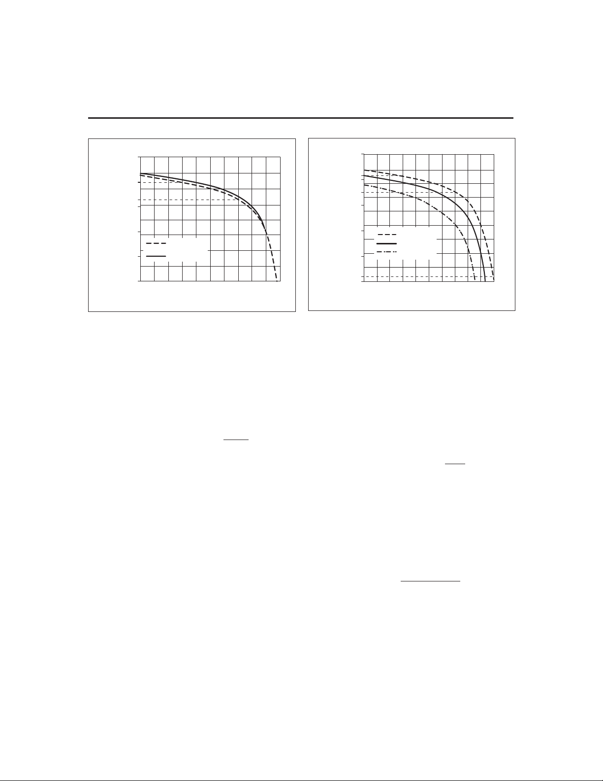
bq2060A
11500
11000
10500
10000
Voltage (mV)
EDV2
EDV1
9500
9000
8500
8000
7500
Battery Low % = 7%, Load = 500mA
45C/500mA
20C/500mA
109876543210
% Capacity
Figure 7. EDV Calculations vs. Capacity
for Various Temperatures
Overvoltage
The 8-bit value, Overvoltage Margin EE 0x48, sets the
limit over ChargingVoltage() that is to be considered as
an overvoltage charge-suspension condition. The voltage in mV above the ChargingVoltage(), VOVM, that
should trigger a charge suspend is encoded in
Overvoltage Margin as follows:
Overvoltage Margin=
VOVM
16
(19)
VOVM is between 0 and 4080mV.
Charging Current
ChargingCurrent() values are either broadcast to a
Level 2 Smart Battery Charger or read from the
bq2060A by a Level 3 Smart Battery Charger. The
bq2060A sets the value of ChargingCurrent(), depending
on the charge requirements and charge conditions of the
pack.
When fast charge is allowed, the bq2060A sets
ChargingCurrent() to the rate programmed in Fast
Charging Current EE 0x1a-0x1b.
When fast charge terminates, the bq2060A sets
ChargingCurrent() to zero and then to the Maintenance
Charging Current EE 0x1c-0x1d when the termination
condition ceases.
When Voltage() is less than EDV0, the bq2060A sets
ChargingCurrent() to Pre-charge Current EE 0x1e-0x1f.
Typically this rate is larger than the maintenance rate
to charge a deeply depleted pack up to the point where it
may be fast charged.
Battery Low % =7%, Temperature = 35 C
11500
11000
EDV2
10500
EDV1
10000
9500
9000
Voltage (mV)
8500
8000
7500
EDV0
7000
109876543210
35C/500mA
35C/1A
35C/2A
% Capacity
Figure 8. EDV Calculations vs. Capacity
for Various Loads
Fast Charging Current, Maintenance Charging Current,
and Pre-Charge Current are stored in mA.
Charge Suspension
During charge, the bq2060A compares the current to the
ChargingCurrent() plus the value IOIM. If the pack is
charged at a current above the ChargingCurrent() plus
IOIM, the bq2060A sets ChargingCurrent() to zero to
stop charging. IOIM is programmed in the EEPROM
value, Overcurrent Margin, encoded as follows:
Overcurrent Margin=
IOIM
16
Overcurrent Margin EE 0x49 may be used to program
IOIM values of 0 to 4080mAin 16mAsteps.
The desired temperature threshold for charge suspen
sion, MAXTEMP, may be programmed between 45°C
and 69°C in 1.6°C steps. Charge-suspension tempera
ture is increased by 16° above the programmed value of
bit5inMiscellaneous Option EE 0x08 is set. MaxT
DeltaT EE 0x45 (most significant nibble) is stored in a
4-bit value as shown:
MaxT=
é
ê
ë
1.6
ù
ú
û
-
69 MAXTEMP
The bq2060A suspends fast charge when fast charge
continues past full by the amount programmed in Maxi
mum Overcharge EE 0x2e-0x2f. Maximum Overcharge
is programmed in 2s complement form of charge in
mAh.
(20)
(21)
-
-
-
35
Page 36

bq2060A
FULLY_CHARGED Bit ClearThreshold
The bq2060A clears the FULLY_CHARGED bit in
BatteryStatus() when RelativeStateOfCharge() reaches
the value, Fully Charged Clear % EE 0x4c. Fully
Charged Clear % is an 8-bit value and is stored as a 2’s
complement of percent.
Fast Charge Termination Percentage
The bq2060A sets RM to a percentage of FCC on charge
termination if the CSYNC bit is set in the Pack Configu
ration register. The percentage of FCC is stored in Fast
Charge Termination % in EE 0x4b. The value is stored
in 2’scomplement of percent.
Cycle Count Threshold
Cycle Count Threshold 0x3c–0x3d sets the number of
mAh that must be removed from the battery to incre
ment CycleCount(). Cycle Count Threshold is a 16-bit
value stored in 2’scomplement of charge in mAh.
∆T/Dt Rate Programming
The ∆T portion of the ∆T/∆t rate is programmed in
DeltaT, the low nibble of MaxT DeltaT EE 0x45 (least
significant nibble). The ∆t portion is programmed in
DeltaT TimeEE 0x4e.
[]
DeltaT
*+
216
/100°
é
ù
∆T/∆t=
[]
DeltaT Time
320- 2Cs
DeltaT D(°C) DeltaT_Time
0 1.6 00 320
1 1.8 01 300
2 2.0 02 280
3 2.2 03 260
4 2.4 04 240
5 2.6 05 220
6 2.8 06 200
7 3.0 07 180
8 3.2 08 160
9 3.4 09 140
a 3.6 0a 120
b 3.8 0b 100
c 4.0 0c 80
d 4.2 0d 60
e 4.4 0e 40
f 4.6 0f 20
ê
ë
*
(22)
ú
û
t (s)
DT/Dt Hold-off Timer Programming
The hold-off timer is programmed in the lower nibble of
Holdoff Time EE 0x4f. The hold-off time is 320s minus
20 times the HoldoffTimevalue.
Hold-off
Time
00 320 08 160
01 300 09 140
02 280 0a 120
03 260 0b 100
04 240 0c 80
05 220 0d 60
-
06 200 0e 40
07 180 0f 20
Hold-off
Time (s)
Hold-off
Time
Hold-off
Time (s)
Current TaperTerminationCharacteristics
Two factors in the EEPROM set the current taper termi
nation for Li-Ion battery packs. The two coded locations
are Current Taper Qual Voltage EE 0x4f and Current
-
Taper Threshold EE 0x4e. Current taper termination oc
curs during charging when the pack voltage is above the
charging voltage minus CELLV (mV) and the charging
current is below the threshold coded in Current Taper
Threshold forat least 80s.
Current Taper Qual Voltage =
Current Taper Threshold =
where i = the desired current termination threshold in
mA, and R
= VFC sense resistor in ohms.
S
CELLV
2
Ri
S*
0.5625
Pack Options
Pack Configuration
Pack Configuration EE 0x3f contains bit-programmable
features.
b7 b6 b5 b4
SEAL
DMODE
CSYNC CEDV VCOR CHEM LCC1 LCC0
DMODE
The DMODE bit determines whether the LED outputs
will indicate AbsoluteStateOfCharge() or
RelativeStateOfCharge()
0 LEDs reflect AbsoluteStateOfCharge()
1 LEDs reflect RelativeStateOfCharge()
b3 b2 b1 b0
-
-
(23)
(24)
36
Page 37

bq2060A
SEAL
The SEAL bit determines the SMBus access state of the
bq2060Aon reset
0 SMBus commands (0x00–0xff) are accessible for
both read and write.
1 SMBus read access is limited to commands
(0x05–0x1c) and (0x20–0x23). SMBus read/write
access is limited to commands (0x00–0x04), (0x2f),
and (0x3c–0x3f).
CSYNC
In usual operation of the bq2060A, the CSYNC bit is set
so that the coulomb counter is adjusted when a fast
charge termination is detected. In some applications, es
pecially those where an externally controlled charger is
used, it may be desirable NOT to adjust the coulomb
counter.In these cases the CSYNC bit should be cleared.
0 The bq2060A does not alter RM at the time of a
valid charge termination.
1 The bq2060A updates RM with a programmed per-
centage of FCC at a valid charge termination.
CEDV
The CEDV bit determines whether the bq2060A implements automatic EDV compensation to calculate the
EDV0, EDV1 and EDV2 thresholds base on rate, temperature, and capacity. If reset, the bq2060A uses the
fixed values programmed in EEPROM for EDV0, EDV1
and EDV2. If set the bq2060A calculates EDV0, EDV1
and EDV2.
0 EDV compensation disabled
1 EDV compensation enabled
VCOR
The VCOR bit enables the midrange voltage correction
algorithm. When set, the bq2060A compares the pack
voltage to RM and may adjust RM according to the val
ues programmed in VOC25, VOC50, and VOC75.
0 Midrange corrections disabled
1 Midrange corrections enabled
CHEM
The CHEM bit configures the bq2060A for nickel packs
(NiCd or NiMH) or Li-Ion packs. When set the bq2060A
employs the configuration parameters in EEPROM des
ignated for Li-Ion. When not set, the bq2060A employs
the configuration parameters designated for nickel.
0 The bq2060A uses nickel configuration parameters.
1 The bq2060A uses Li-Ion configuration parameters.
LCC0 and LCC1
The LCC0 and LCC1 bits configure the cell voltage in
puts (VCELL
No. of Series
Cells LCC1 LCC0
-
).
1–4
Cell Voltage
NA 00 VCELL
201
VCELL
VCELL
VCELL
310
VCELL
VCELL
VCELL
411
VCELL
VCELL
VCELL
Inputs
= Cell Stack
4
= Cell 1
1
= Cell 2
2
= Cell 1
1
= Cell 2
2
= Cell 3
3
= Cell 1
1
= Cell 2
2
= Cell 3
3
= Cell 4
4
For Li-Ion packs with individual measurements, LCC0
and LCC1 define the number of series elements and
their voltage measurement inputs. In each case (2, 3, or
4), the bq2060A uses the highest numbered cell voltage
input to measure the pack voltage measurement as returned with Voltage(). For nickel chemistries or Li-Ion
without single-cell measurements, LCC0 and LCC1
must be set to 00. VCELL
is the pack voltage input for
4
this programming.
Remaining Time andCapacity Alarms
Remaining Time Alarm in EE 0x02–0x03 and Remaining Capacity Alarm in 0x04–0x05set the alarm
thresholds used in the SMBus command codes 0x01 and
0x02, respectively. Remaining Time Alarm is stored in
minutes and Remaining Capacity Alarm in mAh.
Secondary Protection Limits for Li-Ion
The cell undervoltage (VUV) and overvoltage (VOV) limits
are programmed in Cell Undervoltage/Over Voltage EE
0x4a according to the equations:
-
V -4096
Cell Undervoltage/Overvoltage (lower) =
Cell Undervoltage/Overvoltage (upper) =
-
OV
32
V 2048
UV -
64
-
(25)
(26)
37
Page 38

bq2060A
Cell Under/Over
Voltage
(upper nibble)
0 2048 0 4096
1 2112 1 4128
2 2176 2 4160
3 2240 3 4192
4 2304 4 4224
5 2368 5 4256
6 2432 6 4288
7 2496 7 4320
8 2560 8 4352
9 2624 9 4384
a 2688 a 4416
b 2752 b 4448
c 2816 c 4480
d 2880 d 4512
e 2944 e 4544
f 3008 f 4576
Safety Overtemperature EE 0x09 sets Safety
Overtemperature Threshold (SOT) level for the CFC pin.
It can be programmed for a threshold of 69° to 85°C.
This range is increased by 16° if Miscellaneous Options
bit5=1.
SafetyOvertemperature SOT=- *(. )945 10
if Miscellaneous Options bit5=0.
SafetyOvertemperature SOT=-*(. )1105 10
if Miscellaneous Options bit5=1.
V
(mV)
Cell Under/Over
UV
Voltage
(lower nibble)
V
OV
(mV)
Miscellaneous Options
Miscellaneous Options EE 0x08 contains
bit-programmable options. Bits 0–4 should be pro
grammed to zero.
HIT
The HIT bit controls the available temperature range
for maximum temperature.
0
Maximum temperature set in normal 45–85°C
range
1 Maximum temperature set in elevated 61–85°C
range
Cycle Count Initialization
Cycle Count EE 0x0e–0x0f stores the initial value for
the CycleCount() function. It should be programmed to
0x0000.
Control Modes
Control Mode EE0x51 contains additional bit program
mable features.
b7 b6 b5 b4 b3 b2 b1 b0
NDF - HPE CPE LED SC - SM
NDF
The NDF bit disables the digital filter during discharge
if the SMBC and SMBD lines are high.
0 Digital filter enabled all the time
1 Digital filter disabled if SMBC and SMBD are high
HPE
The HPE bit enables/disables PEC transmissions to the
Smart Battery host for master mode alarm messages.
0 No PEC byte on alarm warning to host
1 PEC byte on alarm warning to host
-
b7 b6 b5 b4 b3 b2 b1 b0
NE1 SOT HIT 0 0 0 0 0
NE1
The NE1 bit disables the EDV1 threshold.
0 EDV1 enabled
1 EDV1 disabled
SOT
The SOT bit controls override of the CFC pin for Safety
Overtemperature threshold.
0 CFC control with overvoltage, maximum tempera
ture, and safety overtemperature.
1 CFC control; only with safety overtemperature.
CPE
The CPE bit enables/disables PEC transmissions to the
Smart Battery Charger for master mode alarm mes
sages.
0 No PEC byte on broadcasts to charger
1 PEC byte on broadcasts to charger
LED
The LED bit configures the bq2060A for 4 or 5 LED indi
cation
0 Selects the 5 LED indication mode
1 Selects the 4 LED indication mode
38
-
-
Page 39

bq2060A
SC
The SC bit enables learning cycle optimization for a
Smart Charger or independent charge
0 Learning cycle optimized for independent charger
1 Learning cycle optimized for Smart Charger
SM
The SM bit enables/disables master mode broadcasts by
the bq2060A
0 Broadcasts to host and charger enabled
1 Broadcasts to host and charger disabled
If the SM bit is set, modifications to bits in
BatteryMode() will not re-enable broadcasts.
Measurement Calibration
ADC
To describe how the bq2060A calculates reported battery
and individual cell voltages, the following abbreviations
and designations are used:
VCELL
bq2060A
VCELL1–4 = reported cell voltages
Vnl–4 = voltages at the different series nodes in the
battery
Voltage() = reported battery voltage
V
= voltage across the sense resistor
sr
The reported voltages measurements, Voltage() and
VCELL1–4, may be calibrated by adjusting five 8- or
16-bit registers in EEPROM: ADC Offset in EE0x62,
ADC Voltage Gain in EE 0x66–0x67, Cell 2 Calibration
Factor in EE 0x63, Cell 3 Calibration Factor in EE 0x64,
and Cell 4 Calibration Factor in EE 0x65.
The bq2060A first computes the node voltages Vnl, Vn2,
Vn3, and Vn4. The node voltages are inputs to the volt
age dividers to the VCELL
of the bq2060A. The bq2060A computes node voltages to
calculate the five reported voltages by the bq2060A:
Voltage(), VCELL1, VCELL2, VCELL3, and VCELL4.
An ADC Voltage Gain factor of 20,000 is the nominal
value when using the recommended cell-voltage division
ratios of 16:1 on the VCELL
8:1 on the VCELL
subtracts the voltage across the sense resistor from the
measurements so that the reported voltages reflect the
cell-stack voltages only.
= voltages at the input pins of the
1–4
through VCELL4input pins
1
and VCELL3inputs and
and VCELL1inputs. The bq2060A
2
4
The bq2060Acompute the node voltages as follows:
é
Vn
1
=
ê
ë
Vn2
=
é
Vn3
=
ê
ë
[]
é
ê
ë
é
Vn4
=
ê
ë
[]
é
ê
ë
1
VCELL
é
ê
ë
é
ê
ë
VCELL
ADC Voltage Gai
65536
VCELL
ADC Voltage Gai
65536
32768
*
1250
2
VCELL
*
32768
1250
ADC Voltage Gai
3
*
32768
1250
ù
2
ú
û
4
*
32768
1250
ù
2
ú
û
+
+
ADC Offset
n Cell CalibrationFactor+*
+
ADC Offset
n Cell CalibrationFactor+* *
8
+
ADC Offset
n Cell CalibrationFactor+* *
8
é
ù
ADC Voltage Gai
*ADC Offset
ê
ú
ë
û
82
()
65536
ù
ú
û
()3
ù
*
ú
û
()4
65536
ù
*
ú
û
*
Note: With LCC1-LCC0 = 00, Cell 4 Calibration
Factor =0.
ADC Offset adjusts the ADC reading for voltage and cur
rent measurements. ADC Offset is a signed 8-bit value
that cancels offset present in the circuit with no poten
tial or current flow. ADC Offset is typically set between
-20 and 20.
The bq2060A uses the computed node voltages to calcu
late the reported voltages. It does not compute reported
cell voltages greater than the selected number of nodes.
If no individual cell voltages are to be measured,
LCC1–LCC0 should be set to 00 and the top of the bat
tery stack should be connected to a voltage divider to
-
the VCELL
input.
4
The bq2060Acomputes the reported voltages as follows:
Voltage() = Vn4 (LCC1–LCC0 = 11or 00) - V
Voltage() = Vn3 (LCC1–LCC0 = 10) - V
Voltage() = Vn2 (LCC1–LCC0 = 01) - V
sr
sr
VCELL4 = Vn4 - Vn3
VCELL3 = Vn3 - Vn2
VCELL2 = Vn2 - Vn1
VCELL1 = Vn1 - V
sr
(27)
ù
n
ú
û
(28)
ù
ú
û
(29)
(30)
-
-
-
-
sr
39
Page 40

bq2060A
Current
The bq2060A scales Current() to mA units by the 16-bit
value ADC Sense Resistor Gain in EE 0x68–0x69.
Adjusting ADC Sense Resistor Gain from its nominal
value provides a method to calibrate the current read
ings for variances in the ADC gain, internal voltage ref
erence, and sense resistor value. The bq2060A calculates
Current() by
Current() =
[]
(ADC Reading + )
The nominal value for ADC Sense Resistor Gain is given
by equation (6).
ADC Offset ADC Sense Resistor Gain*
,384
16
VFC
To calibrate the coulomb counting measurement for VFC
gain errors and sense resistor tolerance, the value of
VFC Sense Resistor Gain EE 0x6a-0x6b may be adjusted
from its nominal value.
The nominal value of VFC Sense Resistor Gain is given
by equation (5).
The bq2060A VFC circuit can introduce a signal opposite
in sign from that of the inherent device and circuit offset
to cancel this error. The offset calibration routine is initiated with commands to ManufacturerAccess().
The bq2060A calculates the offset with the calibration
routine and stores the calibration value using the least
21 bits of VFC Offset in EE 0x5e–0x60.
The least 20 bits store the offset calibration value
(OCV). The sign of the offset calibration value is positive
if the 21st bit is 0.
OCV =
0.6V
VFC Offset
u 19 0–
Temperature
The bq2060A uses Temperature Offset in EE 0x61 to cali
brate the Temperature() function for offset. The required
offset adjustment, TOFF (C), sets Temperature Offset ac
cording to the equation
Temperature Offset = TOFF
where
-12.8 ≤ TOFF ≤12.7
10 (33)
*
Constants and String Data
EEPROM Constants
Check/Byte 1 EE 0x00–0x01 and Check Byte 2 EE
0x7e–0x7f must be programmed to 0x3c7f and 0xa55a,
respectively.
-
Specification Information
Specification Information EE 0x14–0x15 stores the de
(31)
fault value for the SpecificationInfo() function. It is
stored in EEPROM in the same format as the data re
turned by the SepcificationInfo().
Manufacture Date
Manufacture Date EE 0x16–0x17 stores the default
value for the ManufactureDate() function. It is stored in
EEPROM in the same format as the data returned by
the ManufactureDate().
Serial Number
Serial Number EE 0x18–0x19 stores the default value
for the SerialNumber() function. It is stored in
EEPROM in the same format as the data returned by
the SerialNumber().
Manufacturer Name Data
Manufacturer Name Length EE 0x20 stores the length
of the desired string that is returned by the
ManufacturerName() function. Locations EE 0x21–0x2a
store the characters for ManufacturerName() in ASCII
code.Device Name Data
Device Name Length EE 0x30 stores the length of the
desired string that is returned by the DeviceName()
function. Locations EE 0x31–0x37 store the characters
for DeviceName() in ASCII code.
Device Chemistry Data
(32)
Device Chemistry Length EE 0x40 stores the length of
the desired string that is returned by the
DeviceChemistry() function. Locations EE 0x41–0x44
store the characters for DeviceChemistry() in ASCII
code.
-
Manufacturers Data Length
Manufacturers Data Length EE 0x50 stores the length
of the desired number of bytes that is returned by the
ManufacturersData() function. It should be set to 7.
-
-
40
Page 41

bq2060A
Absolute Maximum Ratings
Symbol Parameter Minimum Maximum Unit Notes
V
—Supply voltage Relative to V
CC
–All other pins Relative to V
V
IN
T
OPR
Operating
temperature
SS
SS
Note: Permanent device damage may occur if Absolute Maximum Ratings are exceeded. Functional operation
should be limited to the Recommended DC Operating Conditions detailed in this data sheet. Exposure to
conditions beyond the operational limits for extended periods of time may affect device reliability.
-0.3 +6.0 V
-0.3 +6.0 V
-20 +70 °C Commercial
DC Electrical Characteristics (VCC=2.7–3.7V, T
Symbol
V
CC
I
CC
I
SLP
I
LVOUT
I
VOUT
V
OLS
V
IL
V
IH
V
OL
V
ILS
V
IHS
V
AI
I
RB
V
RBI
Z
AI1
Z
AI2
Low-power storage mode current
Output voltage low: LED1–LED5, CFC,
Output voltage low: THON, CVON I
Output voltage low SMBC, SMBD,
Input voltage low SMBC, SMBD,
Input voltage high SMBC, SMBD,
Input voltage range VCELL
RBI data-retention input current V
Input impedance: SR1, SR2 0–1.25V 10
Input impedance: VCELL
Parameter Conditions Minimum Typical Maximum Unit
Supply voltage 2.7 3.3 3.7 V
Operating current
V
OUT
1.5V < V
V
leakage current V
OUT
V
source current
OUT
DFC
OUT
V
OUT
V
OUT=VCC
I
OLS
OLS
Input voltage low DISP -0.3 0.8 V
Input voltage high DISP 2.0 VCC+ 0.3 V
= 1.0mA
I
HDQ16, ESCL, ESDA
OL
HDQ16, ESCL, ESDA
HDQ16, ESCL, ESDA
, TS,
1–4
SRC
> 3.0V,VCC< 2.0V 10 50 nA
RBI
RBI data-retention voltage 1.3 V
, TS, SRC
1–4
0–1.25V 5
= -20–70°C, Unless Otherwise Noted)
OPR
inactive
< 3.7V
CC
inactive
active,
- 0.6V
= 5mA
= 5mA 0.36 V
Note: ZAIspecifications are reference numbers based on process data.
180 235
510
-0.2 0.2
-5.0 mA
0.4 V
0.4 V
-0.3 0.8 V
1.7 6.0 V
- 0.3
V
SS
1.25 V
µA
µA
µA
MΩ
MΩ
41
Page 42

bq2060A
VFC Characteristics (V
= 3.1–3.5V, T
CC
= 0–70°C Unless Otherwise Noted))
OPR
Symbol Parameter Conditions Minimum Typical Maximum Unit
Input voltage range, V
V
SR
V
SROS
V
SRCOS
RM
VCO
RM
TCO
INL
Note: RM
TCO
and V
SR1
VSRinput offset
Calibrated offset –16 +16
Supply voltage gain
coefficient (see Note)
Temperature gain
coefficient (see note)
Integral nonlinearity
error
total deviation is from the nominal gain at 25°C.
REG Characteristics (T
SR2
V
Slope for T
Total Deviation T
Slope for T
Total Deviation T
= -20–70°C)
OPR
VSR=V
SR2=VSR1
disabled
V
T
OPR
SR2–VSR1
, autocorrection
= 3.3V
CC
= –20 to 70°C
OPR
= –20 to 70°C
OPR
=–0to50°C
OPR
=–0to50°C
OPR
= 0–50C
–0.25 +0.25 V
–250 –50 250
µV
µ
0.8 1.2 %/V
–0.09 +0.09 %/°C
–1.6 0.1 %
–0.05 +0.05 %/°C
–0.6 0.1 %
0.21 %
Symbol Parameter Conditions Minimum Typical Maximum Unit
V
I
REG controlled output voltage
RO
REG
REG output current 1.0
JFET: R
(on) < 150Ω
ds
V
(off) < –3.0V @ 10µA
gs
3.1 3.3 3.5 V
V
A
µ
42
Page 43

bq2060A
SMBus AC Specifications (VCC=2.7–3.7V, T
= -20–70°C, Unless Otherwise Noted)
OPR
Symbol Parameter Conditions Min. Typ. Max. Unit
F
SMB
F
MAS
T
BUF
T
HD:STA
T
SU:STA
T
SU:STO
T
HD:DAT
T
SU:DAT
T
TIMEOUT
T
LOW
T
HIGH
T
LOW:SEXT
T
LOW:MEXT
Notes: 1. The bq2060A will time out when any clock low exceeds T
SMBus operating frequency Slave mode, SMBC 50% duty cycle 10 100 kHz
SMBus master clock frequency
Bus free time between start and
stop
Master mode, no clock low slave
extend
51.2 kHz
4.7
Hold time after (repeated) start 4.0
Repeated start setup time 4.7
Stop setup time 4.0
Data hold time
Receive mode 0 ns
Transmit mode 300 ns
Data setup time 250 ns
Error signal/detect See Note 1 25 35 ms
Clock low period 4.7
Clock high period See Note 2 4.0 50
Cumulative clock low slave
extend time
Cumulative clock low master
extend time
2. T
Max. is minimum bus idle time. SMBC = SMBD=1fort>50µs will cause reset of any
HIGH
See Note 3 25 ms
See Note 4 10 ms
.
TIMEOUT
transaction involving bq2060A that is in progress.
3. T
LOW:SEXT
is the cumulative time a slave device is allowed to extend the clock cycles in one message
from initial start to the stop. The bq2060Atypically extends the clock only 20µs as a slave in the read
byte or write byte protocol.
4. T
LOW:MEXT
is the cumulative time a master device is allowed to extend the clock cycles in one message from initial start to the stop. The bq2060A typically extends the clock only 20µs as a master in
the read byte or write byte protocol.
µs
µs
µs
µ
µs
µs
s
HDQ16 AC Specifications (VCC=2.7–3.7V, T
= -20–70 C, Unless Otherwise Noted)
OPR
Symbol Parameter Conditions Min. Typ. Max. Unit
t
CYCH
t
CYCB
t
STRH
t
STRB
t
DSU
t
DSUB
t
t
t
SSU
t
SSUB
t
RSPS
t
DH
DV
t
BR
B
Cycle time, host to bq2060A(write) 190 - -
Cycle time, bq2060Ato host (read) 190 205 250
Start hold time, host to bq2060A
(write)
5--ns
Start hold time, bq2060A to host (read) 32 - -
Data setup time - - 50
Data setup time - - 50
Data hold time 100 - Data valid time 80 - Stop setup time - - 145
Stop setup time - - 145
Response time, bq2060Ato host 190 - 320
Break time 190 - -
Break recovery time 40 - -
43
µs
µs
µs
µs
µ
µs
µs
µs
µs
µs
µs
µs
s
Page 44

bq2060A
SMBus Timing Data
HDQ16 Break Timing
HDQ16 Host to bq2060A
t
STRH
t
DSU
HDQ16 bq2060A to Host
t
STRB
t
DSUB
t
DV
t
SSUB
t
DH
t
SSU
t
B
Write "1"
Write "0"
t
CYCH
Read "1"
Read "0"
t
CYCB
t
BR
TD201803.eps
44
TD201805.eps
Page 45
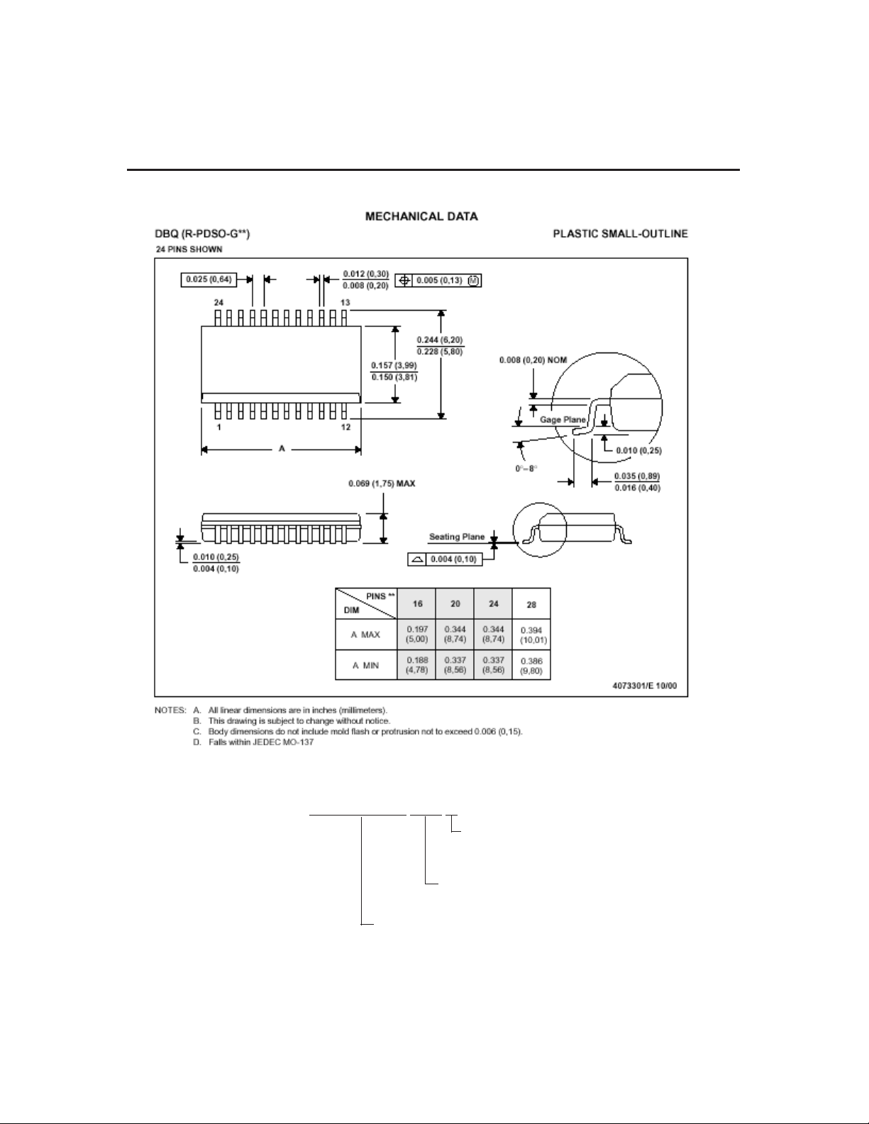
bq2060A
Ordering Information
bq2060A-E619 DBQ
Tapeand Reel
blank = tubes
R = tape and reel
Package Option:
DBQ = 28-pin SSOP
Device:
bq2060ASBS v1.1-Compliant Gas Gauge IC
45
Page 46

IMPORTANT NOTICE
Texas Instruments and its subsidiaries (TI) reserve the right to make changes to their products or to dis
continue any product or service without notice, and advise customers to obtain the latest version of rele
vant information to verify, before placing orders, that information being relied on is current and complete.
All products are sold subject to the terms and conditions of sale supplied at the time of order acknowl
edgement, including those pertainingto warranty,patent infringement,and limitation of liability.
TI warrants performance of its semiconductor products to the specifications applicable at the time of
sale in accordance with TI’s standard warranty. Testing and other quality control techniques are utilized
to the extent TI deems necessary to support this warranty. Specific testing of all parameters of each de
vice is not necessarilyperformed, exceptthose mandatedby governmentrequirements.
CERTAIN APPLICATIONS USING SEMICONDUCTOR PRODUCTS MAY INVOLVE POTENTIAL
RISKS OF DEATH, PERSONAL INJURY, OR SEVERE PROPERTY OR ENVIRONMENTAL DAMAGE
(“CRITICAL APPLICATIONS”). TI SEMICONDUCTOR PRODUCTS ARE NOT DESIGNED, AUTHO
RIZED, OR WARRANTED TO BE SUITABLE FOR USE IN LIFE-SUPPORT DEVICES OR SYSTEMS
OR OTHER CRITICAL APPLICATIONS. INCLUSION OF TI PRODUCTS IN SUCH APPLICATIONS IS
UNDERSTOODTOBE FULLYATTHE CUSTOMER’SRISK.
In order to minimize risks associated with the customer’s applications, adequate design and operating
safeguards must be providedby thecustomer tominimize inherentor procedural hazards.
TI assumes no liability for applications assistance or customer product design. TI does not warrant or
represent that any license, either express or implied, is granted under any patent right, copyright, mask
work right, or other intellectual property right of TI covering or relating to any combination, machine, or
process in which such semiconductor products or services might be or are used. TI’s publication of information regarding any third party’s products or services does not constitute TI’s approval, warranty or
endorsement thereof.
-
-
-
-
-
Copyright © 2002, Texas Instruments Incorporated
46
 Loading...