

bq2040
Gas Gauge IC With SMBus Interface
Features
Provides accurate measurement
➤
of available charge in NiCd,
NiMH, and Li-Ion batteries
Supports SBS v1.0 data set and
➤
two-wire interface
Monitors charge FET in Li-Ion
➤
pack protection circuit
Designed for battery pack inte
➤
gration
Low operating current
-
Complete circuit can fit on less
-
than ¾ square inch of PCB
space
➤ Supports SBS charge control
commands for NiCd, NiMH, and
Li-Ion
➤ Drives a four-segment LED dis-
play for remaining capacity
General Description
The bq2040 Gas Gauge IC With
SMBus Interface is intended for
battery-pack or in-system installa
tion to maintain an accurate record
of available battery charge. The
bq2040 directly supports capacity
monitoring for NiCd, NiMH, and LiIon battery chemistries.
The bq2040 uses the System Man
agement Bus v1.0 (SMBus) protocol
and supports the Smart Battery
Data (SBData) commands. The
bq2040 also supports the SBData
charge control functions. Battery
state-of-charge, remaining capacity,
remaining time, and chemistry are
available over the serial link.
Battery-charge state can be directly
indicated using a four-segment LED
display to graphically depict battery
full-to-empty in 25% increments.
indication
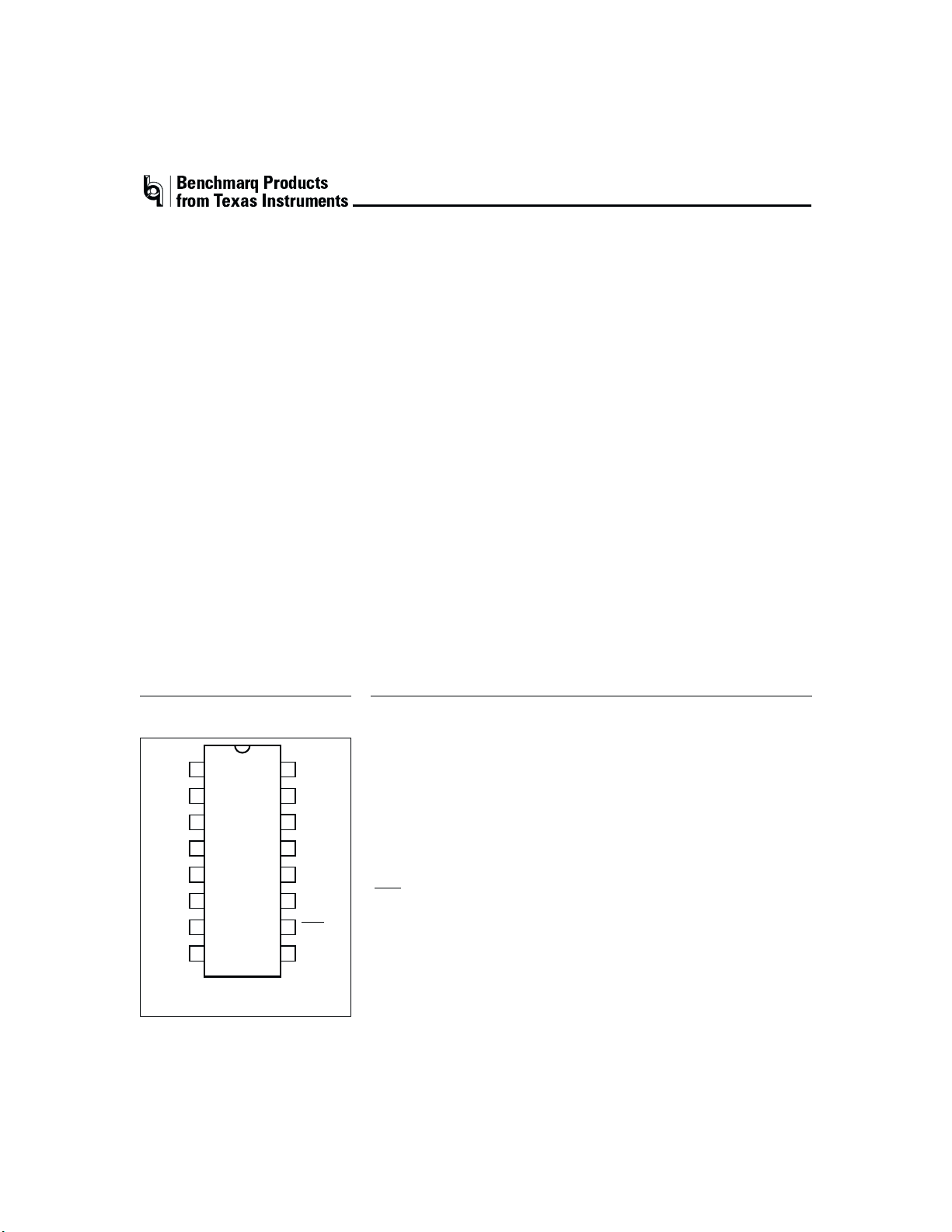
➤ 16-pin narrow SOIC
Pin Connections Pin Names
The bq2040 estimates battery selfdischarge based on an internal
timer and temperature sensor and
user-programmable rate informa
tion stored in external EEPROM.
The bq2040 also automatically re
calibrates or “learns” battery capac
ity in the full course of a discharge
cycle from full to empty.
The bq2040 may operate directly
from three nickel chemistry cells.
With the REF output and an exter
nal transistor, a simple, inexpensive
regulator can be built to provide
V
for other battery cell configu
CC
rations.
An external EEPROM is used to
program initial values into the
bq2040 and is necessary for proper
operation.
-
-
-
-
-
V
ESCL
ESDA
LED
LED
LED
LED
V
SLUS005–JUNE 1999 E
1
CC
2
3
4
1
5
2
6
3
7
4
8
SS
16-Pin Narrow SOIC
V
16
V
OUT
15
REF
14
SMBC
13
SMBD
12
PSTAT
11
SB
10
DISP
9
SR
PN204001.eps
ESCL EEPROM clock
ESDA EEPROM data
LED
V
SR Sense resistor input
DISP Display control input
CC
1-4
SS
3.0–6.5V
LED segment 1-4
System ground
SB Battery sense input
PSTAT Protector status input
SMBD SMBus data input/output
SMBC SMBus clock
REF Voltage reference output
V
EEPROM supply output
OUT
1

bq2040
Pin Descriptions
V
CC
ESCL
ESDA Serial memory data and address
LED
LED
V
SS
SR
Supply voltage input
Serial memory clock
Output used to clock the data transfer be
tween the bq2040 and the external non
volatile configuration memory.
Bidirectional pin used to transfer address
and data to and from the bq2040 and the ex
ternal nonvolitile configuration memory.
LED display segment outputs
–
1
4
Each output may drive an external LED.
Ground
Sense resistor input
The voltage drop (V
) across pins SR and
SR
VSSis monitored and integrated over time
to interpret charge and discharge activity.
The SR input is connected to the sense resistor and the negative terminal of the
battery. VSR<VSSindicates discharge, and
VSR>VSSindicates charge. The effective
voltage drop, V
, as seen by the bq2040
SRO
is VSR+VOS. (See Table 3.)
DISP
Display control input
DISP high disables the LED display. DISP
floating allows the LED display to be active
during charge if the rate is greater than
100mA. DISP low activates the display for
-
-
SB
4 seconds.
Secondary battery input
Monitors the pack voltage through a highimpedance resistor divider network. The
pack voltage is reported in the SBD register
-
function Voltage (0x09) and is monitored for
end-of-discharge voltage and charging volt
age parameters.
PSTAT
Protector status input
Provides overvoltage status from the Li-Ion
protector circuit and can initiate a charge sus
pend request.
SMBD
SMBus data
Open-drain bidirectional pin used to transfer
address and data to and from the bq2040.
SMBC
SMBus clock
Open-drain bidirectional pin used to clock
the data transfer to and from the bq2040.
REF Reference output for regulator
REF provides a reference output for an optional FET-based micro-regulator.
V
OUT
Supply output
Supplies power to the external EEPROM con
figuration memory.
-
-
-
2
bq2040
Functional Description
General Operation
The bq2040 determines battery capacity by monitoring
the amount of charge put into or removed from a re
chargeable battery. The bq2040 measures discharge
and charge currents, estimates self-discharge, and
monitors the battery for low-battery voltage thresholds.
The charge is measured by monitoring the voltage
across a small-value series sense resistor between the
battery's negative terminal and ground. The available
battery charge is determined by monitoring this voltage
over time and correcting the measurement for the envi
ronmental and operating conditions.
V
V
CC
ESCL
SMBC
ESDA
SMBD
LED1
LED2
PS TAT
LED3
LED4
V
SS
bq2040
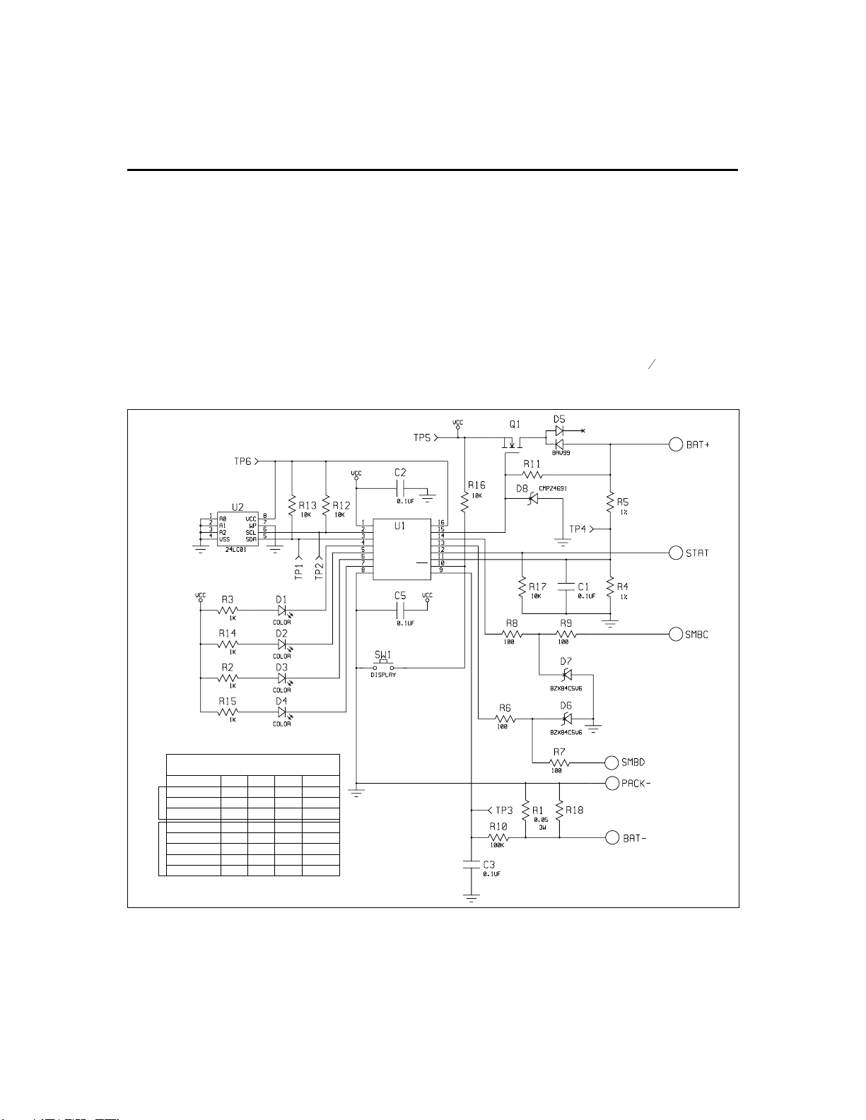
Figure 1 shows a typical battery pack application of the
bq2040 using the LED capacity display, the serial port,
and an external EEPROM for battery pack program
ming information. The bq2040 must be configured and
calibrated for the battery-specific information to ensure
proper operation. Table 1 outlines the configuration in
formation that must be programmed in the EEPROM.
An internal temperature sensor eliminates the need
for an external thermistor—reducing cost and compo
nents. An internal, temperature-compensated timebase eliminates the need for an external resonator,
further reducing cost and components. The entire cir
cuit in Figure 1 can occupy less than
board space.
(Optional)
OUT
REF
SB
DISP
SR
3
square inch of
4
-
-
-
-
No. of Cells
Li-IonNiMH
Chart 1
For bq2040 With No D8
R5 R4 Q1R11
301K BSS138
2
499K
3
4
698K
6
499K
8
698K
9
806K
10
909K
12
909K
Figure 1. Battery Pack Application Diagram—LED Display
604K
806K
604K
499K
806K
499K
604K
909K
100K
100K
100K
100K
100K
100K
100K
86.5K
BSS138
2N7002
BSS138
BSS138
2N7002
2N7002
2N7002
(Optional)
2040LED.eps
3

bq2040
Table 1. Configuration Memory Map
Parameter Name Address Description Length Units
EEPROM length 0x00
EEPROM check1 0x01 EEPROM data integrity check byte, must = 0x5b 8 bits NA
Remaining time alarm 0x02/0x03 Sets RemainingTimeAlarm (0x02) 16 bits minutes
Remaining capacity alarm 0x04/0x05 Sets RemainingCapacityAlarm (0x01) 16 bits mAh
Reserved 0x06/0x07 Reserved for future use 16 bits NA
Initial charging current 0x08/0x09 Sets the initial charging current 16 bits mA
Charging voltage 0x0a/0x0b Sets ChargingVoltage (0x15) 16 bits mV
Battery status 0x0c/0x0d Initializes BatteryStatus (0x16) 16 bits NA
Cycle count 0x0e/0x0f Initializes and stores CycleCount (0x17) 16 bits cycles
Design capacity 0x10/0x11 Sets DesignCapacity (0x18) 16 bits mAh
Design voltage 0x12/0x13 Sets DesignVoltage (0x19) 16 bits mV
Specification information 0x14/0x15 Programs SpecificationInfo (0x1a) 16 bits NA
Manufacture date 0x16/0x17 Programs ManufactureDate (0x1b) 16 bits NA
Serial number 0x18/0x19 Programs SerialNumber (0x1c) 16 bits NA
Fast-charging current 0x1a/0x1b Sets ChargingCurrent (0x14) 16 bits mA
Maintenance-charge current 0x1c/0x1d Sets the trickle current request 16 bits mA
Reserved 0x1e/0x1f Reserved must = 0x0000 16 bits mAh
Manufacturer name 0x20-0x2b Programs ManufacturerName (0x20) 96 bits NA
Current overload 0x2c/0x2d Sets the overload current threshold 16 bits mA
Battery low % 0x2e Sets the battery low amount 8 bits %
Reserved 0x2f Reserved for future use 8 bits NA
Device name 0x30-0x37 Programs DeviceName (0x21) 64 bits NA
Li-Ion taper current 0x38/0x39
Maximum overcharge limit 0x3a/0x3b Sets the maximum amount of overcharge 16 bits NA
Reserved 0x3c Reserved must = 0x00 8 bits NA
Access protect 0x3d Locks commands outside of the SBS data set 8 bits NA
FLAGS1 0x3e Initializes FLAGS1 8 bits NA
FLAGS2 0x3f Initializes FLAGS2 8 bits NA
Device chemistry 0x40-0x45 Programs DeviceChemistry (0x22) 48 bits NA
Current measurement gain 0x46/0x47 Sense resistor calibration value 16 bits NA
Battery voltage offset 0x48 Voltage calibration value 8 bits NA
Temperature offset 0x49 Temperature calibration value 8 bits NA
Maximum temperature and
∆T step
0x4a
Number of EEPROM data locations
must = 0x64
Sets the upper limit of the taper current for charge
termination
Sets the maximum charge temperature and the ∆T
step for ∆T/∆t termination
8 bits NA
16 bits mA
8 bits NA
4

bq2040
Table 1. Configuration Memory Map (Continued)
Parameter Name Address Description Length Units
Charge efficiency 0x4b Sets the high/low charge rate efficiencies 8 bits NA
Full charge percentage 0x4c
Digitial filter 0x4d Sets the minimum charge/discharge threshold 8 bits NA
Current integration gain 0x4e
Self-discharge rate 0x4f Sets the battery’s self-discharge rate 8 bits NA
Manufacturer data 0x50-0x55 Programs ManufacturerData (0x23) 48 bits NA
Voltage gain1 0x56/0x57 Battery divider calibration value 16 bits NA
Reserved 0x58-0x59 Reserved 16 bits NA
EDVF charging current 0x5a/0x5b
End of discharge voltage1 0x5c/0x5d Sets EDV1 16 bits NA
End of discharge voltage final 0x5e/0x5f Sets EDVF 16 bits NA
Full-charge capacity 0x60/0x61 Initializes and stores FullChargeCapacity (0x10) 16 bits mAh
∆t step
Hold-off time 0x63
EEPROM check 2 0x64
Reserved 0x65-0x7f Reserved for future use NA
0x62
Sets the percent at which the battery is consid
ered fully charged
Programs the current integration gain to the
sense resistor value
Sets the charge current request when the battery
voltage is less than EDVF
Sets the ∆t step for ∆T/∆t termination
Sets ∆T/∆t hold-off timer
EEPROM data integrity check byte
must = 0xb5
8 bits NA
8 bits NA
16 bits NA
8 bits NA
8 bits NA
8 bits NA
5

bq2040
Voltage Thresholds
In conjunction with monitoring VSRfor charge/discharge
currents, the bq2040 monitors the battery potential
through the SB pin. The voltage potential is deter
mined through a resistor-divider network per the fol
lowing equation:
R
MBV
5
R
2.25
4
where MBV is the maximum battery voltage, R
1=−
is con
5
nected to the positive battery terminal, and R4is con
nected to the negative battery terminal. R5/R4should be
rounded to the next higher integer. The voltage at the
SB pin (VSB) should never exceed 2.4V.
The battery voltage is monitored for the end-ofdischarge voltages (EDV1 and EDVF) and for alarm
warning conditions. EDV threshold levels are used to de
termine when the battery has reached a programmable
“empty” state. The bq2040 generates an alarm warning
when the battery voltage exceeds the maximum charging voltage by 5% or if the voltage is below EDVF. The
battery voltage gain, the two EDV thresholds, and the
charging voltage are programmable in the EEPROM.
is below either of the two EDV thresholds, the associ-
If V
SB
ated flag is latched and remains latched, independent of
VSB, until the next valid charge.
EDV monitoring may be disabled under certain conditions. If the discharge current is greater than the value
stored in location 0x2c and 0x2d in the EEPROM (EE
0x2c/0x2d), EDV monitoring is disabled and resumes after the current falls below the programmed value.
Reset
The bq2040 is reset when first connected to the battery
pack. On power-up, the bq2040 initializes and reads the
EEPROM configuration memory. The bq2040 can also
be reset with a command over the SMBus. The software
reset sequence is the following: (1) write MaxError
(0x0c) to 0x0000; (2) write the reset register (0x64) to
0x8009. A software reset can only be performed if the
bq2040 is in an unlocked state as defined by the value in
location 0x3d of the EEPROM (EE 0x3d) on power-up.
Temperature
The bq2040 monitors temperature sensing using an in
ternal sensor. The temperature is used to adapt charge
and self-discharge compensations as well as to monitor
for maximum temperature and∆T/∆t during a bq2040
controlled charge. Temperature may also be accessed
over the SMBus with command 0x08.
Layout Considerations
The bq2040 measures the voltage differential between
the SR and VSSpins. VOS(the offset voltage at the SR
pin) is greatly affected by PC board layout. For optimal
results, the PC board layout should follow the strict rule
of a single-point ground return. Sharing high-current
ground with small signal ground causes undesirable
noise on the small signal nodes. Additionally, in refer
ence to Figure 1:
-
The capacitors (C1 and C2) should be placed as close as
n
-
possible to the SB and VCCpins, and their paths to V
should be as short as possible. A high-quality ceramic
capacitor of 0.1µf is recommended for VCC.
The sense resistor capacitor (C3) should be placed as
n
close as possible to the SR pin.
-
The bq2040 should be in thermal contact with the
n
cells for optimum temperature measurement.
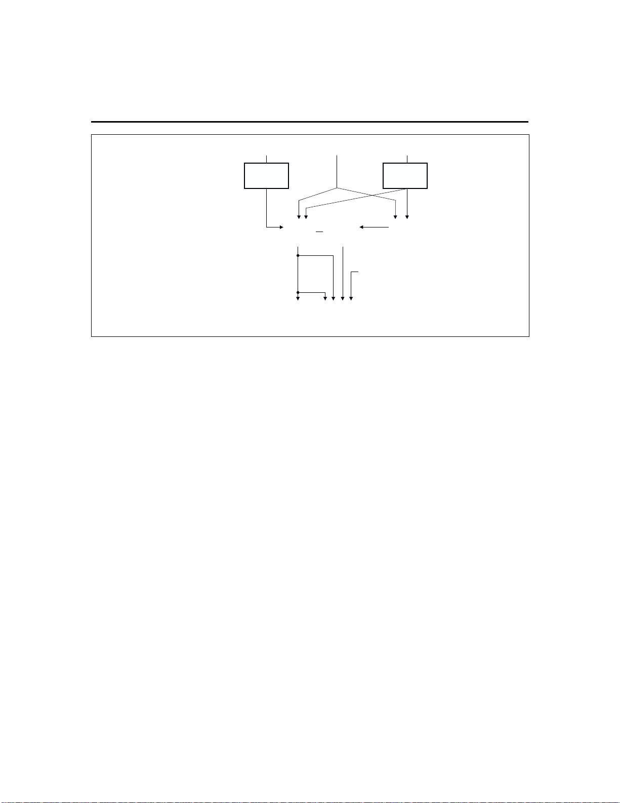
Gas Gauge Operation
The operational overview diagram in Figure 2 illustrates the operation of the bq2040. The bq2040 accumulates a measure of charge and discharge currents, as
well as an estimation of self-discharge. Charge currents
are compensated for temperature and state-of-charge of
the battery. Self-discharge is temperature-compensated.
The main counter, RemainingCapacity (RM), represents
the available battery capacity at any given time. Battery
charging increments the RM register, whereas battery discharging and self-discharge decrement the RM register
and increment the internal Discharge Count Register
(DCR).
The Discharge Count Register is used to update the
FullChargeCapacity (FCC) register only if a complete
battery discharge from full to empty occurs without any
partial battery charges. Therefore, the bq2040 adapts
its capacity determination based on the actual condi
tions of discharge.
The battery's initial full capacity is set to the value stored
in EE 0x60-0x61. Until FCC is updated, RM counts up to,
but not beyond, this threshold during subsequent charges.
The battery’s empty state is also programmed in the
EEPROM. The battery low percentage (EE 0x2e) stores
the percentage of FCC that will be written to RM when
the battery voltage drops below the EDV1 threshold.
1. FullChargeCapacity or learned-battery
capacity:
FCC is the last measured discharge capacity of the
battery. On initialization (application of V
FCC is set to the value stored in the EEPROM. Dur
CC
-
SS
-
or reset),
-
6
bq2040
Inputs
Main Counters
and Capacity
Reference (FCC)
Outputs
Charge
Current
State-of-charge
Temperature
Compensation
Figure 2. Operational Overview
ing subsequent discharges, FCC is updated with the
latest measured capacity in the Discharge Count Register plus the battery low amount, representing a discharge from full to below EDV1. A qualified discharge is necessary for a capacity transfer from the
DCR to the FCC register. Once updated, the bq2040
writes the new FCC to the EEPROM. The FCC also
serves as the 100% reference threshold used by the
relative state-of-charge calculation and display.
2. DesignCapacity (DC):
The DC is the user-specified battery capacity and is
programmed from external EEPROM. The DC also
provides the 100% reference for the absolute dis
play mode.
3. RemainingCapacity (RM):
RM counts up during charge to a maximum value of
FCC and down during discharge and self-discharge to
0. RM is set to the battery low amount after the
EDV1 threshold has been reached. If RM is already
equal to or less than the battery low amount, RM is
not modified. If RM reaches the battery low amount
before the battery voltage falls below EDV1 on dis
charge, RM stops counting down until the EDV1
threshold is reached. RM is set to 0 when the battery
voltage reaches EDVF. To prevent overstatement of
charge during periods of overcharge, RM stops in
crementing when RM = FCC. RM may optionally
be written to a user-defined value when fully
charged if the battery pack is under bq2040 charge
control. On initialization,RM is set to 0.
and
Remaining
+
Chip-Controlled
Available Charge
LED Display
Capacity
(RM)
Discharge
Current
--
<
Serial Interface
Full
Charge
Capacity
(FCC)
Two-Wire
Self-Discharge
Timer
Temperature
Compensation
+
Discharge
Count
Qualified
Register
Transfer
(DCR)
Temperature, Other Data
FG294501.eps
4. Discharge Count Register (DCR):
The DCR counts up during discharge independent
of RM and can continue increasing after RM has
decremented to 0. Prior to RM = 0, both discharge
and self-discharge increment the DCR. After RM
= 0, only discharge increments the DCR. The DCR
resets to 0 when RM = FCC and stops counting at
EDV1 on discharge. The DCR does not roll over but
stops counting when it reaches FFFFh.
FCC is updated on the first charge after a qualified
discharge to EDV1. The updated FCC equals the
battery low percentage times the current FCC plus
-
the DCR value. A qualified discharge to EDV1 oc
curs if all of the following conditions exist:
n
No valid charge initiations (charges greater than
10mAh, where V
the period between RM = FCC and EDV1 de
tected.
n
The self-discharge count is not more than
256mAh.
n
-
The low temperature fault bit in FLAGS2 is not
set when the EDV1 level is reached during dis
charge.
n
-
Battery voltage is not more than 256mV below
the EDV1 threshold when EDV1 is set.
The valid discharge flag (VDQ) in FLAGS1 indi
cates whether the present discharge is valid for an
FCC update. FCC cannot be reduced by more than
256mAh during any single cycle.
+
SRO
>+V
occurred during
SRD
-
-
-
-
7

bq2040
Charge Counting
Charge activity is detected based on a positive voltage
on the SR input. If charge activity is detected, the
bq2040 increments RM at a rate proportional to V
and, if enabled, activates an LED display. Charge ac
tions increment the RM after compensation for charge
state and temperature.
The bq2040 determines charge activity sustained at a
continuous rate equivalent to V
charge equates to sustained charge activity
greater than 10 mAh. Once a valid charge is detected,
charge threshold counting continues until V
low V
scribed in the Digital Magnitude Filter section.
SRD
.V
SRD
is a programmable threshold as de
SRO
>+V
SRD
SRO
SRO
. A valid
falls be
Discharge Counting
All discharge counts where V
register to decrement and the DCR to increment. V
is a programmable threshold as described in the Digital
Magnitude Filter section.
SRO
<-V
cause the RM
SRD
SRD
Self-Discharge Estimation
The bq2040 continuously decrements RM and increments DCR for self-discharge based on time and temperature provided that the discharge flag in BatteryStatus
is set (charge not detected). The bq2040 self-discharge
estimation rate is programmed in EE 0x4f and can be
set from 0 to 25% per day for 20–30°C. This rate approximately doubles for every 10°C increase until the temperature is ≥ 70°C or halves every 10°C decrease until
the temperature is < 10°C.
Charge Control
The bq2040 supports SBS charge control by broadcast
ing the ChargingCurrent and the ChargingVoltage to
the Smart Charger address. The bq2040 broadcasts
charging commands every 10 seconds; the broadcasts
can be disabled by writing bit 14 of BatteryMode to 1.
On reset, the initial charging current broadcast to the
charger is set to the value programmed in EE 0x080x09. The bq2040 updates the value used in the charg
ing current broadcasts based on the battery’s state of
charge, voltage, and temperature.
The bq2040 internal charge control is compatible with
nickel-based and Li-Ion chemistries. The bq2040 uses
current taper detection for Li-Ion primary charge termi
nation and ∆T/∆t for nickel based primary charge termi
nation. The bq2040 also provides a number of safety
terminations based on battery capacity, voltage, and
temperature.
Current Taper
For Li-Ion charge control, the ChargingVoltage must be
set to the desired pack voltage during the constant volt
age charge phase. The bq2040 detects a current taper
termination when it measures the pack voltage to be
within 128mV of the requested charging voltage and
when the AverageCurrent is less than the programmed
threshold in EE 0x38—0x39 and non-zero for at least
100s.
∆T/∆t
-
The ∆T/∆t used by the bq2040 is programmable in both
-
the temperature step (1.6°C–4.6°C) and time step (20
seconds–320seconds). Typical settings for 1°C/min in
clude 2°C over 120 seconds and 3°C over 180 seconds.
Longer times are required for increased slope resolution.
∆
T
is set by the formula:
∆
t
[]
(lower nibble of EE 0x4a) 2 + 16 / 10
[(
In addition to the ∆T/∆t timer, there is a hold-off timer,
which starts when the battery is being charged at more
than 255mA and the temperature is above 25°C. Until
this timer expires, ∆T/∆t is suspended. If the temperature falls below 25°C, or if charging current falls below
255mA, the timer is reset and restarts only if these conditions are once again within range. The hold-off time is
programmed in EE 0x63.
EE 0x62
−320
∆
T
∆
=
t
) 20)]
∗
Charge Termination
Once the bq2040 detects a valid charge termination, the
Fully_Charged, Terminate_Charge_Alarm, and the
Over_Charged_Alarm bits are set in BatteryStatus, and
the requested charge current is set to zero. Once the
terminating conditions cease, the Termi
nate_Charge_Alarm and the Over_Charged_Alarm are
cleared, and the requested charging current is set to the
maintenance rate. The bq2040 requests the mainte
nance rate until RM falls below the amount determined
by the programmable full- charge percentage. Once this
occurs, the Fully_Charged bit is cleared, and the re
quested charge current and voltage are set to the
fast-charge rate.
Bit 4 (CC) in FLAGS2 determines whether RM is modi
-
fied after a ∆T/∆t or current taper termination occurs. If
CC = 1, RM may be set from 0 to 100% of the FullChar
geCapacity as defined in EE 0x4c. If RM is below the
full-charge percentage, RM is set to the full-charge per
centage of FCC. If RM is above the full-charge percent
age, RM is not modified.
-
-
o
C
s∗
-
-
-
-
-
-
-
8

bq2040
Charge Suspension
The bq2040 may temporarily suspend charge if it detects
a charging fault. The charging faults include the follow
ing conditions:
Maximum Overcharge: If charging continues for
n
more than the programmed maximum overcharge
limit as defined in EE 0x3a—0x3b beyond RM=FCC,
the Fully_Charged bit is set, and the requested
charging current is set to the maintenance rate.
Overvoltage: An over-voltage fault exists when the
n
bq2040 measures a voltage more than 5% above the
ChargingVoltage. When the bq2040 detects an
overvoltage condition, the requested charge current is
set to 0 and the Terminate_Charge_Alarm bit is set
in BatteryStatus. The alarm bit is cleared when the
current drops below 256mA and the voltage is less
than 105% of ChargingVoltage.
Overcurrent: An overcurrent fault exists when the
n
bq2040 measures a charge current more than 25%
above the ChargingCurrent. If the ChargingCurrent
is less than 1024mA, an overcurrent fault exists if the
charge current is more than 1mA above the lowest
multiple of 256mA that exceeds the ChargingCurrent.
When the bq2040 detects an overcurrent condition, the
requested charge current is set to 0 and the
Terminate_Charge_Alarm bit is set in Battery Status.
The alarm bit is cleared when the current drops below
256mA.
n
Maximum Temperature: When the battery
temperature equals the programmed maximum
temperature, the requested charge current is set to
zero and the Over_Temp_Alarm and the
Terminate_Charge_Alarm bits are set in Battery
Status. The Over_Temp_Alarm bit is cleared when
the temperature drops to 43°C below the maximum
temperature threshold minus 5°C.
n
PSTAT: When the PSTAT input is ≥1.5V, the
requested charge current is set to 0 and the
Terminate_Charge_Alarm bit is set in BatteryStatus
if the Discharging flag is not set. The alarm bit is
cleared when the PSTAT input is <1.0V or the
Discharging flag is set.
n
Low Temperature: When the battery temperature
is less than 12°C (LTF bit in FLAGS2 set), the
requested charge current is set to the maintenance
rate. Once the temperature is above 15°C, the
requested charge current is set to the fast rate.
n
Undervoltage: When the battery voltage is below
the EDVF threshold, the requested charge current is
set to the EDVF rate stored in EE0x5a/0x5b. Once
the voltage is above EDVF, the requested charge
current is set to the fast or maintenance rate
depending on the state of the LTF bit.
Count Compensations
Charge activity is compensated for temperature and
state-of-charge before updating the RM and/or DCR.
Self-discharge estimation is compensated for tempera
ture before updating RM or DCR.
Charge Compensation
Charge efficiency is compensated for state-of-charge,
temperature, and battery chemistry. The charge effi
ciency is adjusted using the following equations:
1.)
RM RM * Q Q
=−()
EFC ET
where RelativeStateOfCharge < FullChargePercentage,
and
ing from 0.75 to 1.0.
is the programmed fast-charge efficiency vary
Q
EFC
2.)
RM RM Q Q
=−*( )
ETC ET
where RelativeStateOfCharge ≥ FullChargePercentage
and
charge efficiency varying from 0.75 to 1.0.
Q
ET
temperature increases according to the following:
QifT
QCTC
QTC
Q
ET
is the programmed maintenance (trickle)
Q
ETC
is used to adjust the charge efficiency as the battery
=<030
ET
=°≤<°002 30 40.if
ET
=≥°005 40.if
ET
°C
is 0 over the entire temperature range for Li-Ion.
Digital Magnitude Filter
The bq2040 has a programmable digital filter to elimi
nate charge and discharge counting below a set
threshold, V
. Table 2 shows typical digital filter
SRD
settings. The proper digital filter setting can be calcu
lated using the following equation.
DMF =
45
SRD
V
Table 2. Typical Digital Filter Settings
DMF DMF Hex. V
75 4B
100 64 0.45
150 96 0.30
175 AF 0.26
200 C8 0.23
SRD
(mV)
0.60
-
-
-
-
-
9

bq2040
Table 3. bq2040 Current-Sensing Errors
Symbol Parameter Typical Maximum Units Notes
V
OS
INL
INR
Offset referred to V
Integrated non-linearity
error
Integrated nonrepeatability error
SR
75
±
1
±
0.5
±
150
±
4
±
1
±
V DISP
µ
%
%
= VCC.
Add 0.1% per °C above or below 25°C
and 1% per volt above or below 4.25V.
Measurement repeatability given
similar operating conditions.
Error Summary
Capacity Inaccurate
The FCC is susceptible to error on initialization or if no
updates occur. On initialization, the FCC value includes
the error between the design capacity and the actual ca
pacity. This error is present until a qualified discharge
occurs and FCC is updated (see the DCR description).
The other cause of FCC error is battery wear-out. As the
battery ages, the measured capacity must be adjusted to
account for changes in actual battery capacity. Periodic
qualified discharges from full to empty will minimize errors in FCC.
Current-Sensing Error
Table 3 illustrates the current-sensing error as a function of VSR. A digital filter eliminates charge and discharge counts to the RM register when -V
+V
.
SRD
Display
The bq2040 can directly display capacity information using low-power LEDs. The bq2040 displays the battery
charge state in either absolute or relative mode. In rela
tive mode, the battery charge is represented as a per
centage of the FCC. Each LED segment represents 25%
of the FCC.
In absolute mode, each segment represents a fixed
amount of charge, 25% of the DesignCapacity. As the
battery wears out over time, it is possible for the FCC to
be below the design capacity. In this case, all of the
LEDs may not turn on in absolute mode, representing
the reduction in the actual battery capacity.
When DISP is tied to VCC, the LED
tive. When DISP is left floating, the display becomes ac
tive whenever the bq2040 detects a charge rate of
100mA or more. When pulled low, the segment outputs
become active immediately for a period of approximately
4 seconds. The DISP pin must be returned to float or
VCCto reactivate the display.
LED1blinks at a 4Hz rate indicating a low battery con
dition whenever the display is active, EDVF is not set,
SRD<VSRO
outputs are inac
1-4
and Remaining_Capacity_Alarm is set. V
(EDVF = 1) disables the display output.
below EDVF
SB
Microregulator
The bq2040 can operate directly from three nickel chem
-
istry cells. To facilitate the power supply requirements
of the bq2040, an REF output is provided to regulate an
external low-threshold n-FET. A micropower source for
the bq2040 can be built inexpensively using a 2N7002 or
BSS138 FET and an external resistor. (See Figure 1.)
The value of R11 depends on the battery pack’s nominal
voltage.
Communicating With the bq2040
The bq2040 includes a simple two-pin (SMBC and
SMBD) bi-directional serial data interface. A host proc-
<
essor uses the interface to access various bq2040 registers; see Table 4. This method allows battery characteristics to be monitored easily. The open-drain SMBD and
SMBC pins on the bq2040 are pulled up by the host system, or may be connected to VSS, if the serial interface is
not used.
-
The interface uses a command-based protocol, where the
-
host processor sends the battery address and an eightbit command byte to the bq2040. The command directs
the bq2040 to either store the next data received to a
register specified by the command byte or output the
data specified by the command byte.
bq2040 Data Protocols
The host system, acting in the role of a Bus master, uses
the read word and write word protocols to communicate
integer data with the bq2040. (See Figure 3).
-
Host-to-bq2040 Message Protocol
The Bus Host communicates with the bq2040 using one
of three protocols:
n
Read word
-
n
Write word
-
10

bq2040
Battery Address
S
0001011
Battery Address
S
0001011
Battery Address
S
0001011
Byte Count =N Data byte 1
0 A Command Code A Data byte low A Data byte high AP
Write Word
0 A Command Code A Battery Address A1
AA
Read Word
A Command Code A Battery Address A1
0
AA
1818
Block Read
1
S
1818
PData byte low Data byte high
1
S
Figure 3. Host Communication Protocols
Read block
n
The particular protocol used is a function of the command. The protocols used are shown in Figure 3.
Host-to-bq2040 Messages
(see Table 4)
ManufacturerAccess() (0x00)
This read/write word is an open location.
Input/Output: word.
RemainingCapacityAlarm() (0x01)
This function sets or returns the low-capacity alarm
value. When RM falls below the RemainingCapac
ityAlarm value initialized from the external EE
PROM, the Remaining_Capacity_Alarm bit is set in
BatteryStatus. The system may alter this alarm dur
ing operation.
Input/Output: unsigned integer. This sets/returns
the value where the Remaining_Capacity_Alarm
bit is set in Battery Status.
Units: mAh
Range: 0 to 65,535mAh
RemainingTimeAlarm() (0x02)
This function sets or returns the low remaining time
alarm value. When the AverageTimeToEmpty falls be
low this value, the Remaining_Time_Alarm bit in Bat
teryStatus is set. The default value for this register is
programmed in EE 0x02-0x03.. The system may alter
this alarm during operation.
11818181171
117181171
System Host
117181171
1
AA
1818
PData byte 2 Data byte N
bq2040
A – ACKNOWLEDGE
A – NOT ACKNOWLEDGE
S – START
P – STOP
FG204001.eps
Input/Output: unsigned integer. This sets/returns
the value where the Remaining_Time_Alarm bit is
set in Battery Status.
Units: minutes
Range: 0 to 65,535 minutes
BatteryMode() (0x03)
This read/write word selects the various battery operational modes. The bq2040 supports the battery capacity
information specified in mAh. This function also determines whether the bq2040 charging values are broadcasted to the Smart Battery Charger address.
Writing bit 14 to 1 disables voltage and current Master
-
Mode broadcasts to the Smart Battery Charger. Bit 14 is
-
automatically reset to 0 if SMBC and SMBD = 0 for
greater than 2 seconds (i.e.pack removal).
Writing bit 13 to 1 disables all Master Mode broadcasts
including alarm messages to the Smart Battery Charger
and Host. The bit remains set until overwritten. Pro
gramming bit 3 of FLAGS2 in the EEPROM (EE0x3f)
initializes this bit to a 1.
Bit 7 is the condition request flag. It is set when the
bq2040 is initialized from the EEPROM and reset when a
learning cycle has been completed. It is also set toa1if
CycleCount increases by 32 without a new learning cycle.
AtRate() (0x04)
This read/write word is the first half of a two-function
set used to set the AtRate value used in calculations
made by the AtRateTimeToFull and AtRateTime
ToEmpty.
-
-
11

bq2040
Table 4. bq2040 Register Functions
Function Code Access Units Defaults
ManufacturerAccess 0x00 read/write - -
RemaningCapacityAlarm 0x01 read/write mAh E
RemainingTimeAlarm 0x02 read/write minutes E
BatteryMode 0x03 read/write bit flag -
AtRate 0x04 read/write mA -
AtRateTimeToFull 0x05 read minutes -
AtRateTimeToEmpty 0x06 read minutes -
AtRateOK 0x07 read Boolean -
Temperature 0x08 read 0.1°K 2930
Voltage 0x09 read mV E
Current 0x0a read mA 0
AverageCurrent 0x0b read mA 0
MaxError 0x0c read percent 100
RelativeStateOfCharge 0x0d read percent -
AbsoluteStateOfCharge 0x0e read percent -
RemainingCapacity 0x0f read mAh E
FullChargeCapacity 0x10 read mAh E
RunTimeToEmpty 0x11 read minutes -
AverageTimeToEmpty 0x12 read minutes -
AverageTimeToFull 0x13 read minutes -
ChargingCurrent 0x14 read mA E
ChargingVoltage 0x15 read mV E
Battery Status 0x16 read bit flags E
CycleCount 0x17 read cycle E
DesignCapacity 0x18 read mAh E
DesignVoltage 0x19 read mV E
SpecificationInfo 0x1a read - E
ManufactureDate 0x1b read - E
SerialNumber 0x1c read integer E
Reserved 0x1d - 0x1f - - -
ManufacturerName 0x20 read string E
DeviceName 0x21 read string E
1
2
2
2
2
2
2
2
2
2
2
2
2
2
2
2
2
Note: 1. Defaults after reset or power-up.
12

bq2040
Table 4. bq2040 Register Functions (Continued)
Function Code Access Units Defaults
DeviceChemistry 0x22 read string E
ManufacturerData 0x23 read string E
FLAG1 and FLAG2 0x2f read bit flags E
End of Discharge Voltage 1 (EDV1) 0x3e read - E
End of Discharge Voltage Final
(EDVF)
Note: 1. Defaults after reset or power-up.
0x3f read - E
1
2
2
2
2
2
13

bq2040
When the AtRate value is positive, the
n
AtRateTimeToFull function returns the predicted
time to full-charge at the AtRate value of charge.
When the AtRate value is negative, the
n
AtRateTimeToEmpty function returns the predicted
operating time at the AtRate value of discharge.
Input/Output: signed integer. AtRate is positive
for charge and negative for discharge.
Units: mA
Range: -32,768mA to 32,767mA
AtRateTimeToFull() (0x05)
This read-only word returns the predicted remaining
time to fully charge the battery at the AtRate value
(mA) and is valid only if read immediately after an
AtRate command.
Output: unsigned integer. Returns the predicted
time to full charge.
Units: minutes
Range: 0 to 65,534min
Granularity: 2 min or better
Invalid Data Indication: 65,535 indicates that the
AtRate value is negative.
AtRateTimeToEmpty() (0x06)
This read-only word returns the predicted remaining operating time if the battery is discharged at the AtRate
value and is valid only if read immediately after an
AtRate command.
Output: unsigned integer. Returns the predicted
time to empty.
Units: minutes
Range: 0 to 65,534min
Granularity: 2min or better
Invalid Data Indication: 65,535 indicates that the
AtRate value is not negative.
AtRateOK() (0x07)
This read-only word returns a Boolean value that indi
cates whether or not the EDVF flag has been set.
Boolean: Indicates if the battery can supply addi
tional energy.
Units: Boolean
Range: TRUE ≠0, FALSE = 0
-
Temperature()(0x08)
This read-only word returns the cell-pack's internal
temperature.
Output: unsigned integer. Returns the cell tem
perature in tenths of degrees Kelvin increments.
Units: 0.1°K
Range: 0 to +500.0°K
Granularity: 0.5°K or better
Accuracy:±3°K after calibration
Voltage() (0x09)
This read-only word returns the cell-pack voltage (mV).
Output: unsigned integer. Returns the battery ter
minal voltage in mV.
Units: mV
Range: 0 to 65,535mV
Granularity: 0.2% of DesignVoltage
Accuracy:±1% of DesignVoltage after calibration
Current() (0x0a)
This read-only word returns the current through the
battery's terminals (mA).
Output: signed integer. Returns the charge/discharge rate in mA, where positive is for charge
and negative is for discharge
Units: mA
Range: 0 to 32,767mA for charge or 0 to
–32,768mA for discharge
Granularity: 0.2% of the DesignCapacity or better
Accuracy:±1% of the DesignCapacity after calibration
AverageCurrent()(0x0b)
This read-only word returns a rolling average of the cur
rent through the battery's terminals. The AverageCur
rent function returns meaningful values after the bat
tery's first minute of operation.
-
Output: signed integer. Returns the charge/dis
charge rate in mA, where positive is for charge
and negative is for discharge
Units: mA
Range: 0 to 32,767mA for charge or 0 to
–32,768mA for discharge
Granularity: 0.2% of the DesignCapacity or better
-
-
-
-
-
-
14

bq2040
Accuracy:±1% of the DesignCapacity after cali
bration
-
MaxError() (0x0c)
Returns the expected margin of error (%) in the state of
charge calculation.
Output: unsigned integer. Returns the percent un
certainty for selected information.
Units: %
Range: 0 to 100%
-
RelativeStateOfCharge() (0x0d)
This read-only word returns the predicted remaining
battery capacity expressed as a percentage of FullChar
geCapacity (%). RelativeStateOfCharge is only
valid for battery capacities more than 1504mAh
and less than 10,400mAh.
Output: unsigned integer. Returns the percent of remaining capacity.
Units: %
Range: 0 to 100%
Granularity: 1%
Accuracy: ±MaxError after circuit and capacity
calibration
AbsoluteStateOfCharge() (0x0e)
This read-only word returns the predicted remaining
battery capacity expressed as a percentage of DesignCapacity (%). Note that AbsoluteStateOfCharge can return
values greater than 100%. Absolute StateOfCharge
is only valid for battery capacities more than
1504mAh and less than 10,400mAh.
Output: unsigned integer. Returns the percent of
remaining capacity.
Units: %
Range: 0 to 65,535%
Granularity: 1%
Accuracy: ±MaxError after circuit and capacity
calibration
RemainingCapacity() (0x0f)
This read-only word returns the predicted remaining
battery capacity. The RemainingCapacity value is ex
pressed in mAh.
Output: unsigned integer. Returns the estimated re
maining capacity in mAh.
Units: mAh
Range: 0 to 65,535mAh
Granularity: 0.2% of DesignCapacity or better
Accuracy: ±MaxError ∗ FCC after circuit and ca
pacity calibration
FullChargeCapacity() (0x10)
-
This read-only word returns the predicted pack capacity
when it is fully charged. FullChargeCapacity defaults
to the value programmed in the external EEPROM until
a new pack capacity is learned. The new FCC is stored
to EEPROM within 400ms of a valid charge after a
qualified discharge.
Output: unsigned integer. Returns the estimated full
charge capacity in mAh.
Units: mAh
Range: 0 to 65,535mAh
Granularity: 0.2% of DesignCapacity or better
Accuracy: ±MaxError ∗ FCC after circuit and ca-
pacity calibration
RunTimeToEmpty() (0x11)
This read-only word returns the predicted remaining
battery life at the present rate of discharge (minutes).
The RunTimeToEmpty value is calculated based on
Current.
Output: unsigned integer. Returns the minutes of
operation left.
Units: minutes
Range: 0 to 65,534min
Granularity: 2min or better
Invalid data indication: 65,535 indicates battery is
not being discharged.
-
-
-
AverageTimeToEmpty() (0x12)
This read-only word returns the predicted remaining
battery life at the present average discharge rate (min
utes). The AverageTimeToEmpty is calculated based on
AverageCurrent.
15
-

bq2040
Output: unsigned integer. Returns the minutes of
operation left.
Units: minutes
Range: 0 to 65,534min
Granularity: 2min or better
Invalid data indication: 65,535 indicates battery
is not being discharged.
AverageTimeToFull() (0x13)
This read-only word returns the predicted time until the
Smart Battery reaches full charge at the present aver
age charge rate (minutes).
Output: unsigned integer. Returns the remaining
time in minutes to full.
Units: minutes
Range: 0 to 65,534min
Granularity: 2min or better
Invalid data indication: 65,535 indicates battery
is not being charged.
ChargingCurrent() (0x14)
If enabled, the bq2040 sends the desired charging rate in
mA to the Smart Battery Charger.
Output: unsigned integer. Transmits/returns the
maximum charger output current in mA.
Units: mA
Range: 0 to 65,534mA
Granularity: 0.2% of the design capacity or better
Invalid data indication: 65,535 indicates that the
Smart Charger should operate as a voltage source
outside its maximum regulated current range.
ChargingVoltage() (0x15)
If enabled, the bq2040 sends the desired voltage in mV
to the Smart Battery Charger.
Output: unsigned integer. Transmits/returns the
charger voltage output in mV.
Units: mV
Range: 0 to 65,534mV
Granularity: 0.2% of the DesignVoltage or better
Invalid data indication: 65,535 indicates that the
Smart Battery Charger should operate as a cur
rent source outside its maximum regulated voltage
range.
-
BatteryStatus() (0x16)
This read-only word returns the battery status word.
Output: unsigned integer. Returns the status reg
ister with alarm conditions bitmapped as shown in
Table 5.
Some of the BatteryStatus flags (Remaining_Capac
ity_Alarm and Remaining_Time_Alarm) are calculated
based on current. See Table 8 and 9 for definitions.
Table 5. Status Register
-
Alarm Bits
0x8000 Over_Charged_Alarm
0x4000 Terminate_Charge_Alarm
0x2000 Reserved
0x1000 Over_Temp_Alarm
0x0800 Terminate_Discharge_Alarm
0x0400 Reserved
0x0200 Remaining_Capacity_Alarm
0x0100 Remaining_Time_Alarm
Status Bits
0x0080 Initialized
0x0040 Discharging
0x0020 Fully_Charged
0x0010 Fully_Discharged
Error Code
0x0000-
0x000f
Reserved for error codes
CycleCount() (0x17)
This read-only word returns the number of charge/dis
charge cycles the battery has experienced. A charge/dis
charge cycle starts from a base value equivalent to the
battery's state-of-charge on completion of a charge cycle.
The bq2040 increments the cycle counter during the cur
rent charge cycle if the battery has been discharged 15%
below the state-of-charge at the end of the last charge cy
cle. This prevents false reporting of small charge/discharge
cycles. The cycle count is stored in EEPROM within
400ms of an update.
Output: unsigned integer. Returns the count of
charge/discharge cycles the battery has
experienced.
Units: cycles
-
-
-
-
-
-
16

bq2040
Table 6. Bit Descriptions for FLAGS1 and FLAGS2
(MSB) 7 6543210 (LSB)
FLAGS2 DMODE PSTAT CHM CC - OV LTF OC
FLAGS1
Note: - = Reserved
∆T/∆t
I
MIN
VQ - VDQ OVLD EDV1 EDVF
Range: 0 to 65,535 cycles; 65,535 indicates battery
has experienced 65,535 or more cycles.
Granularity: 1 cycle
DesignCapacity() (0x18)
This read-only word returns the theoretical capacity of a
new pack. The DesignCapacity value is expressed in
mAh at the nominal discharge rate.
Output: unsigned integer. Returns the battery capacity in mAh.
Units: mAh
Range: 0 to 65,535mAh
DesignVoltage() (0x19)
This read-only word returns the theoretical voltage of
a new pack in mV.
Output: unsigned integer. Returns the battery's
normal terminal voltage in mV.
Units: mV
Range: 0 to 65,535mV
SpecificationInfo() (0x1a)
This read-only word returns the specification re
vision the bq2040 supports.
-
ManufactureDate() (0x1b)
This read-only word returns the date the cell was manu
factured in a packed integer word. The date is packed
as follows: (year - 1980) ∗ 512 + month ∗ 32+day.
Field
Month 5–8
Year 9–15
Bits
Used Format Allowable Value
Day 0–4
5-bit binary
value
4-bit binary
value
7-bit binary
value
1–31 (corresponds to
date)
1–12 (corresponds to
month number)
0–127 (corresponds to
year biased by 1980)
SerialNumber() (0x1c)
This read-only word returns a serial number. This
number, when combined with the ManufacturerName,
the DeviceName, and the ManufactureDate, uniquely
identifies the battery.
Output: unsigned integer
ManufacturerName() (0x20)
This read-only string returns a character string where the
first byte is the number of characters available. The maximum number of characters is 11. The character string contains the battery manufacturer's name. For example,
“Benchmarq” identifies the battery pack manufacturer as
Benchmarq.
Output: string or ASCII character string
DeviceName() (0x21)
This read-only string returns a character string where the
first byte is the number of characters available. The maximum number of characters is 7. The 7-byte character string
contains the battery's name. For example, a DeviceName of
“bq2040” indicates that the battery is a model bq2040.
Output: string or ASCII character string
DeviceChemistry() (0x22)
This read-only string returns a character string where
the first byte is the number of characters available. The
maximum number of characters is 5. The 5-byte charac
ter string contains the battery's chemistry. For example,
if the DeviceChemistry function returns “NiMH,” the
battery pack contains nickel-metal hydride cells.
Output: string or ASCII character string
ManufacturerData() (0x23)
This read-only string allows access to an up to 5-byte
manufacturer data string.
Output: block data—data whose meaning is as
signed by the Smart Battery's manufacturer.
-
-
17

bq2040
End of Discharge Voltage1 (0x3e)
This read-only word returns the first end-of-discharge
voltage programmed for the pack.
Output: two’s complemented unsigned integer.
Returns battery end-of-discharge voltage pro
grammed in EEPROM in mV.
-
End of Discharge VoltageF (0x3f)
This read-only word returns the final end-of-discharge
voltage programmed for the pack.
Output: two’s complemented unsigned integer.
Returns battery final end-of-discharge voltage pro
grammed in EEPROM in mV.
-
FLAGS1&2()(0x2f)
This read-only register returns an unsigned integer rep
resenting the internal status registers of the bq2040.
The MSB represents FLAGS2, and the LSB represents
FLAGS1. See Table 6 for the bit description for FLAGS1
and FLAGS2.
-
FLAGS2
The Display Mode flag (DMODE), bit 7 determines
whether the bq2040 displays Relative or Absolute capacity.
The DMODE value is:
FLAGS2 Bits
7 6543210
DMODE -------
Where DMODE is:
0 Selects Absolute display
1 Selects Relative display
Bit 6 reflects the high/low state of PSTAT. PSTAT ≥1.5V
generates a charge suspend condition.
The PSTAT value is:
FLAGS2 Bits
7 6 543210
-PSTAT------
Where PSTAT is:
0 PSTAT input < 1.0V
1 PSTAT input ≥ 1.5V
The Chemistry flag (CHM), bit 5, selects Li-Ion or nickel
compensation factors.
The CHM value is:
FLAGS2 Bits
76 5 43210
--CHM-----
Where CHM is:
0 Selects Nickel
1 Selects Li-Ion
Bit 4, the Charge Control flag (CC), determines whether
a bq2040-based charge termination will set RM to a
user-defined programmable full charge capacity.
The CC value is:
FLAGS2 Bits
76 5 43210
-- - CC----
Where CC is:
0 RM is not modified on valid bq2040
charge termination
1 RM is set to a programmable percentage of
the FCC when a valid bq2040 charge termination occurs
Bit 3 is reserved.
Bit 2, the Overvoltage flag (OV), is set when the bq2040
detects a pack voltage 5% greater than the programmed
charging voltage. This bit is cleared when the pack voltage falls 5% below the programmed charging voltage.
The OV value is:
FLAGS2 Bits
76 5 43210
- - - - -OV- -
Where OV is:
0 Voltage < 1.05∗ChargingVoltage
1 Voltage≥1.05∗ChargingVoltage
Bit 1, the Low Temperature Fault flag (LTF), is set when
Temperature is < 12°C and cleared when Temperature
is ≥ 15°C.
The LTF value is:
FLAGS2 Bits
76 5 43210
-- - ---LTF-
18

bq2040
Where LTF is:
0 Temperature > 15°C
1 Temperature < 12°C
Bit 0, the Overcurrent flag (OC), is set when Current is
25% greater than the programmed charging current. If
the charging current is programmed less than 1024mA,
overcurrent is set if Current is 256mA greater than the
programmed charging current. This flag is cleared when
Current falls below 256mA.
The OC value is:
FLAGS2 Bits
765432 1 0
------ - OC
Where OC is:
0 Current is less than 1.25 ∗ ChargingCur
rent or less than 256mA if charging current
is programmed less than 1024mA
1 Current exceeds 1.25 ∗ ChargingCurrent or
256mA if the charging current is programmed less than 1024mA. This bit is
cleared if Current < 256mA.
FLAGS1
Bits 7 indicates that a ∆T/∆t termination condition
exists.
The ∆T/∆t value is:
FLAGS1 Bits
7 6 5 43210
∆T/∆t
Where ∆T/∆t is:
Bit 6 indicates that a current taper termination condi
tion exists.
7 6 5 43210
- - -----
0 The ∆T/∆t rate drops below the pro
-
grammed rate.
1 The ∆T/∆t rate exceeds the programmed
rate.
FLAGS1 Bits
-I
MIN
- -----
The I
Where I
MIN
value is:
is:
MIN
0 A valid current taper termination condition
is not present.
1 Valid current taper termination condition
detected.
The Valid Charge flag (VQ), bit 5, is set when V
|V
| and 10mAh of charge has accumulated. This bit
SRD
is cleared during a discharge and when V
SRO
|V
≤
FLAGS1 Bits
76 5 43210
--VQ -----
The VQ value is:
Where VQ is:
|V
0V
SRO
1V
SRO
|
SRD
≤
|V
≥
| and 10mAh of charge has
SRD
accumulated
Bit 4 is reserved.
The Valid Discharge flag (VDQ), bit 3, is set when a
valid discharge is occurring (discharge cycle valid for
learning new full charge capacity) and cleared if a partial charge is detected, EDV1 is asserted when T < 0°C,
or self-discharge accounts for more than 256mAh of the
discharge.
FLAGS1 Bits
7654 3 210
- - - - VDQ - - -
The VDQ value is:
Where VDQ is:
0 Self-discharge is greater than 256mAh,
EDV1 = 1 when T < 0°C or VQ = 1
1 On first discharge after RM=FCC
The Overload flag (OVLD), bit 2, is set when the dis
charge current is greater than the programmed rate and
cleared when the discharge current falls below the pro
grammed rate.
FLAGS1 Bits
76543 2 10
- - - - - OVLD - -
SRD
SRO
|.
≥
-
-
19

bq2040
The OVLD value is:
Where OVLD is:
0 Current < programmed rate
1 Current > programmed rate
The First End-of-Discharge Voltage flag (EDV1), bit 1, is
set when Voltage < EDV1 and OVLD = 0 and cleared
when VQ = 1 and Voltage > EDV1.
FLAGS1 Bits
765432 1 0
- - - - - - EDV1 -
The EDV1 value is:
Where EDV1 is:
0 VQ = 1 and Voltage > EDV1
1 Voltage < EDV1 and OVLD = 0
The Final End-of-Discharge Voltage flag (EDVF), bit 0, is
set when Voltage < EDVF and OVLD = 0 and cleared
when VQ = 1 and Voltage > EDVF.
FLAGS1 Bits
7654321 0
- - - - - - - EDVF
The EDVF value is:
Where EDVF is:
0 VQ = 1 and Voltage > EDVF
1 Voltage < EDVF and OVLD = 0
SBD Seal
The bq2040 address space can be “locked” to enforce the
SBS specified access to each command code. To lock the
address space, the bq2040 must be initialized with EE
0x3d set to b0h. Once this is done, only commands
0x00-0x04 may be written. Attempting to write to any
other address will cause a “no acknowledge” of the data.
Reading will only be permitted from the command codes
listed in the SBD specification plus the five locations
designated as optional manufacturing functions 1–5
(0x2f, 0x3c–0x3f).
Programming the bq2040
The bq2040 requires the proper programming of an ex
ternal EEPROM for proper device operation. Each mod
ule can be calibrated for the greatest accuracy, or gen
eral “default” values can be used. An EV2200-40 pro
gramming kit (interface board, software, and cable) for
an IBM-compatible PC is available from Benchmarq.
The bq2040 uses a 24LC01 or equivalent serial EEPROM (capable of read operation to 2.0V) for storing the
various initial values, calibration data, and string information. Table 1 outlines the parameters and addresses
for this information. Tables 10 and 11 detail the various
register contents and show an example program value
for an 2400mAh 4-series Li-Ion battery pack, using a
50mΩsense resistor.
-
-
-
-
Error Codes and Status Bits
Error codes and status bits are listed in Table 8 and Ta
ble 9, respectively.
-
20

bq2040
Table 8. Error Codes (BatteryStatus() (0x16))
Error Code Access Description
OK 0x0000 read/write bq2040 processed the function code without detecting any errors.
Busy 0x0001 read/write bq2040 is unable to process the function code at this time.
ReservedCommand 0x0002 read/write
UnsupportedCommand 0x0003 read/write bq2040 does not support the requested function code.
AccessDenied 0x0004 write
Overflow/Underflow 0x0005 read/write bq2040 detected a data overflow or underflow.
BadSize 0x0006 write
UnknownError 0x0007 read/write bq2040 detected an unidentifiable error.
Note: Reading the bq2040 after an error clears the error code.
bq2040 cannot read or write the data at this time—try again
later.
bq2040 detected an attempt to write to a read-only function
code.
bq2040 detected an attempt to write to a function code with an
incorrect size data block.
21

bq2040
Bit Name Set When: Reset When:
OVER_CHARGED_ALARM
TERMINATE_CHARGE_ALARM
OVER_TEMP_ALARM
TERMINATE_DISCHARGE_ALARM
REMAINING_CAPACITY_ALARM
REMAINING_TIME_ALARM
Bit Name Set When: Reset When:
INITIALIZED
DISCHARGING
FULLY_CHARGED
FULLY_DISCHARGED
Table 9. BatteryStatus Bits
Alarm Bits
The bq2040 detects a ∆T/∆t or cur
rent taper termination. (Note:
∆T/∆t and current taper are valid
charge terminations.)
The bq2040 detects an over-current,
over-voltage, over-temperature,
∆T/∆t, or current taper condition
during charge.
The bq2040 detects that its internal
temperature is greater than the pro
grammed value.
The bq2040 determines that it has
supplied all the charge that it can
without being damaged (Voltage <
EDVF).
The bq2040 detects that the RemainingCapacity is less than that set by
the RemainingCapacityAlarm function.
The bq2040 detects that the estimated remaining time at the present
discharge rate is less than that set
by the RemainingTimeAlarm function.
Status Bits
The bq2040 loads from the EEPROM
(bit 7 set in EE0x0c).
The bq2040 determines that it is not
being charged.
The bq2040 determines a valid
charge termination or a maximum
overcharge state.
bq2040 determines that it has
supplied all the charge that it can
without being damaged.
-
-
A discharge occurs or when the
∆T/∆t or current taper termination
condition ceases during charge.
A discharge occurs or when all condi
tions causing the event cease.
Internal temperature falls to 43°C or
the maximum temperature threshold
minus 5°C.
Voltage > EDVF signifies that the
battery has reached a state of charge
sufficient for it to once again safely
supply power.
Either the value set by the RemainingCapacityAlarm function is lower
than the Remaining Capacity or the
RemainingCapacity is increased by
charging.
Either the value set by the RemainingTimeAlarm function is lower than
the AverageTimeToEmpty or a valid
charge is detected.
A bad EEPROM load is detected.
Battery detects that it is being
charged.
RM discharges below the full charge
percentage.
RelativeStateOfCharge is greater
than or equal to 20%
-
22

Table 10. Example Register Contents
bq2040
EEPROM
Address
Low
Description
EEPROM
length
EEPROM check 1 0x01 5b 91 Must be equal to 0x5b.
Remaining time
alarm
Remaining
capacity alarm
Reserved 0x06 0x07 00 00 0 Not currently used by the bq2040.
Initial charging
current
Charging voltage 0x0a 0x0b d8 40 16600mV
Battery status 0x0c 0x0d 80 00 128 Initializes BatteryStatus.
Cycle count 0x0e 0x0f 00 00 0
Design capacity 0x10 0x11 60 09 2400mAh Normal battery pack capacity.
Design voltage 0x12 0x13 40 38 14400mV Nominal battery pack voltage.
Specification
information
Manufacture
date
Serial number 0x18 0x19 12 27 10002 Contains the optional pack serial number.
Fast-charging
current
Maintenance
charge current
Reserved 0x1e 0x1f 00 00 0 Must be programmed to 0x00.
Current
overload
Battery low % 0x2e 08 3%
High
Byte
Byte
0x00 64 100 Must be equal to 0x64.
0x02 0x03 0a 00 10 minutes Sets the low time alarm level.
0x04 0x05 f0 00 240mAh Sets the low capacity alarm level.
0x08 0x09 60 09
0x14 0x15 10 00 1.0 Default value for this register in a 1.0 part.
0x16 0x17 a1 20
0x1a 0x1b 60 09 2400mA
0x1c 0x1d 00 00 0mA
0x2c 0x2d 70 17 6000mA
EEPROM
Hex Contents
Low
High
Byte
Byte
Example
Values Notes
2400mA
May 1, 1996
= 8353
Sets the initial charge request.
Used to set the fast-charge voltage for the Smart
Charger.
Contains the charge cycle count and can be set to zero
for a new battery.
Packed per the ManufactureDate description.
Used to set the fast-charge current for the Smart
Charger.
Contains the desired maintenance current after fastcharge termination by the bq2040.
Sets the discharge current at which EDV threshold
monitoring is disabled.
Sets the battery capacity that RemainingCapacity is
reduced to at EDV1. The value equals 2.56 ∗ (%RM at
EDV1)
23

bq2040
Table 10. Example Register Contents (Continued)
EEPROM
EEPROM
Address
Low
High
Byte
Description
Byte
Reserved 0x2f 00 0 Not currently used by the bq2040.
Li-Ion taper
current
0x38 0x39 10 ff 240mA
Maximum
overcharge
0x3a 0x3b 9c ff 100mAh
limit
Reserved 0x3c 00 0 Must be programmed to 0.
Access protect 0x3d b0 SBD access only
FLAGS1 0x3e 00 0 Initializes FLAGS1
FLAGS2 0x3f b0
Current
measurement
1
gain
Battery voltage
1
offset
Temperature
1
offset
0x46 0x47 00 0f 3840
0x48 fe -2mV
0x49 8a
Maximum
temperature
0x4a 5f
and ∆T step
Charge
efficiency
Full-charge
percentage
0x4b ff
0x4c 9c
Note: 1. Can be adjusted to calibrate the battery pack.
Hex
Contents
Low
Byte
High
Byte
Relative display
Li-Ion chemistry
bq2040 charge
temperature =
∆T step = 4.6°C
Maintenance
compensation =
Fast compensa
Example
Values Notes
Sets the upper taper limit for Li-Ion charge termina
tion. Stored in 2’s complement.
Sets the maximum amount of overcharge before a
maximum overcharge charge suspend occurs.
Stored in 2’s complement.
If the bq2040 is reset and bit 3 of this location is 0, the
bq2040 locks access to any command outside of the SBS
data set. Program to 0xb8 for full R/W access, 0xb0 for
SBD access only.
Initializes FLAGS2.
control
The current gain measurement and current integration gain are related and defined for the bq2040 current measurement. This word equals 192/sense resistor value in ohms.
Used to adjust the battery voltage offset according to
the following:
Voltage = (VSB(mV) + V
The default value (zero adjustment) for the offset is
13.8°C
Maximum
61.0°C
12.8°C or 0x80.
TOFF
(TEMP
NEW
ACTUAL
= TOFF
- TEMP
CURRENT
Maximum charge temperature is 69- (mt ∗ 1.6)°C (mt
= upper nibble). The ∆T step is (dT ∗ 2 + 16)/10°C
(dT = lower nibble).
Sets the fast-charge (high) and maintenance charge
(low) efficiencies. The upper nibbles sets the low effi
100%
tion = 100%
ciency and the lower nibble adjusts the high effi
ciency according to the equation:
-
Nibble = (efficiency% ∗ 256 - 196)/4
This packed field is the two’s complement of the de
sired value in RM when the bq2040 determines a
100%
full-charge termination. If RM is below this value,
RM is set to this value. If RM is above this value,
then RM is not adjusted.
) ∗ Voltage gain
OFF
+
REPORTED
-
)∗ 10
-
-
-
24

Table 10. Example Register Contents (Continued)
EEPROM
EEPROM
Address
Low
Description
Digital filter 0x4d 96 0.30mV
Current integra
tion gain
Self-discharge rate 0x4f 2d 0.25%
Voltage gain
Reserved 0x58 0x59 00 00 0 Should be programmed to 0.
EDVF charging
current
End of discharge
voltage 1
End-of-discharge
voltage final
Full charge
capacity
∆t step
Hold-off time 0x63 00 320s hold-off
EEPROM check 2 0x64 b5 181 Must be equal to 0xb5.
Reserved 0x65 0x7f NA Not currently used by the bq2040.
Note: 1. Can be adjusted to calibrate the battery pack.
-
1
1
High
Byte
Byte
0x4e 40 0 3.2/0.05
0x56 0x57 17 07 7.09
0x5a 0x5b 64 00 100mA Contains the desired charge current below EDVF.
0x5c 0x5d 20 d1 12000mV
0x5e 0x5f 40 d4 11200mV
0x60 0x61 d0 07 2000mA This value sets the initial estimated pack capacity.
0x62 0f 20s
Hex
Contents
Low
Byte
High
Byte
Example
Values Notes
Used to set the digital magnitude filter as described in
Table 2.
Represents the following: 3.2/sense resistor in ohms.
It is used by the bq2040 to scale the measured voltage
values on the SR pin in mA and mAh. This register
also compensates for variations in the reported sense
resistor value.
This packed field is the two’s complement of (52.73/x)
where x is the desired self-discharge rate per day (%)
at room temperature.
Voltage gain is packed as two units. For example, (R4
+ R5)/R4 = 7.09 would be stored as: whole number
stored in 0x57 as 7 and the decimal component stored
in 0x56 as 256 x 0.09 = 23(= 17h).
The value programmed is the two’s complement of the
threshold voltage in mV.
The value programmed is the two’s complement of the
threshold voltage in mV.
The ∆t step for ∆T/∆t termination equals
320 - (byte value ∗ 20).
The hold-off time is 320 - (byte value ∗ 20).
bq2040
25

bq2040
Table 11. Example Register Contents (String Data)
String Description Address0xX00xX10xX20xX30xX40xX50xX60xX70xX80xX90xXa0xXb
Manufacturer name
Device name
Device chemistry
Manufacturer data
0x200x2b
0x300x37
0x400x45
0x500x55
42B45E4eN43C48H4dM41A52R51
09
42B51Q32230034430
06
6cL69I4fO4e
04
42B51Q32230032
05
N
0
-
2
--
Q
-
26

bq2040
Absolute Maximum Ratings
Symbol Parameter Minimum Maximum Unit Notes
V
CC
All other pins Relative to V
REF Relative to V
V
SR
T
OPR
Note: Permanent device damage may occur if Absolute Maximum Ratings are exceeded. Functional opera
Relative to V
SS
SS
SS
-0.3 +7.0 V
-0.3 +7.0 V
-0.3 +8.5 V Current limited by R11 (see Figure 1)
Minimum 100Ωseries resistor should
Relative to V
SS
-0.3 +7.0 V
be used to protect SR in case of a
shorted battery.
Operating tempera
ture
0 +70 °C Commercial
tion should be limited to the Recommended DC Operating Conditions detailed in this data sheet. Expo
sure to conditions beyond the operational limits for extended periods of time may affect device reliability.
-
-
DC Voltage Thresholds (T
A=TOPR
; V = 3.0 to 5.5V)
Symbol Parameter Minimum Typical Maximum Unit Notes
E
VSB
Battery voltage error relative to SB -50mV - 50mV V See note
Note: The accuracy of the voltage measurement may be improved by adjusting the battery voltage offset and
gain, stored in external EEPROM. For best operation, VCCshould be 1.5V greater than VSB.
27

bq2040
Recommended DC Operating Conditions (T
= T
OPR
)
A
Symbol Parameter Minimum Typical Maximum Unit Notes
V
CC
V
REF
R
REF
I
CC
V
SB
R
SBmax
I
DISP
I
LVO UT
V
SR
R
SR
V
IH
V
IL
V
OL
I
OL
V
OLSL
V
OLSH
V
OHVL
V
OHVH
I
VOUT
I
OLS
Supply voltage 3.0 4.25 6.5 V
Reference at 25°C 5.7 6.0 6.3 V I
Reference at -40°C to +85°C 4.5 - 7.5 V I
Reference input impedance 2.0 5.0 - MΩV
- 90 135
Normal operation
- 120 180
- 170 250
Battery input 0 - V
CC
SB input impedance 10 - - MΩ0 < VSB< V
DISP input leakage - - 5
V
output leakage -0.2 - 0.2
OUT
Sense resistor input -0.3 - 2.0 V
SR input impedance 10 - - MΩ-200mV < VSR< V
Logic input high
0.5 ∗ V
CC
-
V
CC
1.4 - 5.5 V SMBC, SMBD
Logic input low
0-
0.3 ∗ V
CC
-0.5 0.6 V SMBC, SMBD
Data, clock output low - - 0.4 V IOL=350µA, SMBC, SMBD
Sink current 100 - 350
LEDXoutput low, low V
LEDXoutput low, high V
V
output, low V
OUT
V
output, high V
OUT
V
source current -33 - - mA At V
OUT
CC
CC
CC
CC
- 0.1 - V
- 0.4 - V
VCC- 0.3 - - V VCC= 3V, I
VCC- 0.6 - - V VCC= 6.5V, I
LEDXsink current 11.0 - mA At V
VCCexcursion from < 2.0V to
3.0V initializes the unit.
= 5µA
REF
= 5µA
REF
= 3V
REF
AV
µ
AV
µ
AV
µ
CC
CC
CC
= 3.0V
= 4.25V
= 5.5V
V
CC
AV
µ
A EEPROM off
µ
DISP
= V
SS
VSR<VSS= discharge;
VSR> VSS= charge
V ESCL, ESDA
V ESCL, ESDA
AV
µ
0.4V, SMBC, SMBD
≤
OL
VCC= 3V, I
LED
–LED
1
OLS
4
VCC= 6.5V, I
–LED
LED
1
4
VOUT
VOUT
= VCC- 0.6V
OHVH
= 0.4V
OLSH
OLS
Note: All voltages relative to VSS.
CC
1.75mA
≤
11.0mA
≤
= -5.25mA
= -33.0mA
≥
28

AC Specifications
Symbol Parameter Min Max Units Notes
F
SMB
T
BUF
T
HD:STA
T
SU:STA
T
SU:STO
T
HD:DAT
T
SU:DAT
T
LOW
T
HIGH
T
F
T
R
T
LOW:SEXT
T
TIMEOUT
SMBus operating frequency 10 100 KHz
Bus free time between stop and
start condition
Hold time after (repeated) start
condition
4.7
4.0
Repeated start condition setup time 4.7
Stop condition setup time 4.0
µ
µ
µs
µ
Data hold time 300 ns
Data setup time 250 ns
Clock low period 4.7
Clock high period 4.0
µ
µ
Clock/data fall time 300 ns
Clock/data rise time 1000 ns
Cumulative clock low extend time
(slave)
25 ms
25 35 ms
s
s
s
s
s
bq2040
Bus Timing Data
t
t
SU:STO
SU:STA
SMBC
SMBD
t
BUF
t
HD:STA
t
LOW
t
R
t
SU:DAT
t
F
t
HD:DAT
t
HIGH
TD294501.eps
29

bq2040
16-Pin SOIC Narrow (SN)
16-Pin SN(SOIC Narrow
Dimension Minimum Maximum
A 0.060 0.070
D
e
B
E
H
A1 0.004 0.010
B 0.013 0.020
C 0.007 0.010
D 0.385 0.400
E 0.150 0.160
e 0.045 0.055
H 0.225 0.245
L 0.015 0.035
All dimensions are in inches.
)
A
C
A1
.004
L
30

Data Sheet Revision History
ChangeNo. Page No. Description of Change
3 3 Updated recommended application schematic.
3 9 Changed overcurrent fault conditon for ChargingCurrent < 1024mA.
3 10 4Hz operation of LED clarification.
3 11 Added descriptions for bits 7 and 13 of BatteryMode.
3 14 AtRateTimeToEmpty and AtRateTimeToFull invalid data indication correction.
3 15, 16
3 23 Changed typical Battery low % value for Li-Ion with EDV1 = 3.0V/cell.
3 24 Li-Ion taper current is stored in 2’s complement.
324
3 25 Voltage gain is (R4 + R5)/R4.
3 25 Changed typical EDV1 and EDVF values for Li-Ion.
4 6 Added V
4 8 The self discharge rate approx imately doubles or halves
4 11 Changed cycle count increase from 30 to 32 for condition request.
4 14 Changed AtRateOK() indication from EDV1 to EDVF
4 25 Changed self-discharge programming from 52.75/x to 52.73/x.
4 25 Changed recommended EDVF charging current from 0mA to 100mA
Notes: Changes 1 and 2 refer to the 1998 Data Book
Change 3 = June1998 D changes from Jan. 1998 C.
Change 4 = June 1999 E changes from June 1998 D.
RunTimeToEmpty, AverageTimeToEmpty and AverageTimeToFull invalid data
indication corrections.
Changed typical ∆T step and Full-charge percentage for Li-Ion.
should not exceed 2.4V
SB
bq2040
Ordering Information
bq2040
Temperature Range:
blank = Commercial (0 to 70°C)
Package Option:
SN = 16-pin narrow SOIC
Device:
bq2040 Gas Gauge IC With SMBus Interface
31

IMPORTANT NOTICE
T exas Instruments and its subsidiaries (TI) reserve the right to make changes to their products or to discontinue
any product or service without notice, and advise customers to obtain the latest version of relevant information
to verify, before placing orders, that information being relied on is current and complete. All products are sold
subject to the terms and conditions of sale supplied at the time of order acknowledgement, including those
pertaining to warranty, patent infringement, and limitation of liability.
TI warrants performance of its semiconductor products to the specifications applicable at the time of sale in
accordance with TI’s standard warranty. Testing and other quality control techniques are utilized to the extent
TI deems necessary to support this warranty . Specific testing of all parameters of each device is not necessarily
performed, except those mandated by government requirements.
CERTAIN APPLICATIONS USING SEMICONDUCTOR PRODUCTS MAY INVOLVE POTENTIAL RISKS OF
DEATH, PERSONAL INJURY, OR SEVERE PROPERTY OR ENVIRONMENTAL DAMAGE (“CRITICAL
APPLICATIONS”). TI SEMICONDUCTOR PRODUCTS ARE NOT DESIGNED, AUTHORIZED, OR
WARRANTED TO BE SUITABLE FOR USE IN LIFE-SUPPORT DEVICES OR SYSTEMS OR OTHER
CRITICAL APPLICA TIONS. INCLUSION OF TI PRODUCTS IN SUCH APPLICATIONS IS UNDERST OOD TO
BE FULLY AT THE CUSTOMER’S RISK.
In order to minimize risks associated with the customer’s applications, adequate design and operating
safeguards must be provided by the customer to minimize inherent or procedural hazards.
TI assumes no liability for applications assistance or customer product design. TI does not warrant or represent
that any license, either express or implied, is granted under any patent right, copyright, mask work right, or other
intellectual property right of TI covering or relating to any combination, machine, or process in which such
semiconductor products or services might be or are used. TI’s publication of information regarding any third
party’s products or services does not constitute TI’s approval, warranty or endorsement thereof.
Copyright 2000, Texas Instruments Incorporated
 Loading...