

Page 1
User's Guide
SLAU598A–December 2014–Revised July 2015
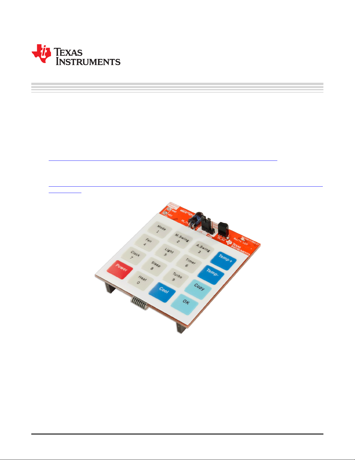
BOOST-IR Infrared (IR) BoosterPack™ Plug-in Module
The BOOST-IR BoosterPack™ Plug-in Module can be plugged into a LaunchPad™ Development Kit for
simple integration of infrared (IR) transceiver functionality. LaunchPad developers can use this
BoosterPack to start developing remote control applications using the on-board keypad, IR LED
transmitter, and IR receiver + demodulator.
Infrared modulation can be simplified by using on-chip IR Modulation Logic, which can be found on select
MSP430 ultra-low-power microcontrollers within the MSP430FRxx MCU series.
Explore IR communication using the MSP430FR4xx and MSP430FR2xx microcontrollers
TI Designs are also available to help accelerate development using IR transceiver capabilities. These
designs contain documentation, design files, and test data to minimize design overhead.
Download a full reference design leveraging the MSP-EXP430FR4133 LaunchPad and BOOST-IR
BoosterPack
Figure 1. BOOST-IR BoosterPack
BoosterPack, LaunchPad, MSP430, Code Composer Studio, E2E are trademarks of Texas Instruments.
All other trademarks are the property of their respective owners.
SLAU598A–December 2014–Revised July 2015 BOOST-IR Infrared (IR) BoosterPack™ Plug-in Module
Submit Documentation Feedback
Copyright © 2014–2015, Texas Instruments Incorporated
1
Page 2

www.ti.com
Contents
1 Getting Started............................................................................................................... 3
2 Hardware...................................................................................................................... 4
3 TI Design and Software Examples....................................................................................... 10
4 Additional Resources ...................................................................................................... 22
5 FAQs......................................................................................................................... 23
6 Schematics.................................................................................................................. 24
List of Figures
1 BOOST-IR BoosterPack .................................................................................................... 1
2 BOOST-IR Overview ........................................................................................................ 4
3 BoosterPack Pinout.......................................................................................................... 5
4 Membrane Keypad Connections........................................................................................... 6
5 IR Transmit Circuit........................................................................................................... 7
6 IR Receive Circuit............................................................................................................ 8
7 Pulse Position Encoding (ASK)........................................................................................... 11
8 IR Modulation Logic Blocks in MSP430FR4133 ....................................................................... 12
9 ASK IR Generation on MSP430FR4133 ................................................................................ 13
10 IR Demodulation............................................................................................................ 13
11 Pulse Distance Encoding.................................................................................................. 14
12 Pulse Distance Protocol, Data Frame Format.......................................................................... 14
13 MSP430FR4133 Pinout ................................................................................................... 16
14 Directing the Project>Import Function to the Demo Project .......................................................... 17
15 When CCS Has Found the Project ...................................................................................... 18
16 BOOST-IR Software Examples in TI Resource Explorer ............................................................. 22
17 Schematics.................................................................................................................. 24
List of Tables
1 IR Receiver Replacement Options ........................................................................................ 8
2 Hardware Change Log...................................................................................................... 9
3 Software Examples ........................................................................................................ 17
4 IDE Minimum Requirements for MSP430FR4133 ..................................................................... 17
5 Source Files and Folders.................................................................................................. 19
6 Source Files and Folders.................................................................................................. 20
7 Current Consumption...................................................................................................... 21
8 Range Testing .............................................................................................................. 21
2
BOOST-IR Infrared (IR) BoosterPack™ Plug-in Module SLAU598A–December 2014–Revised July 2015
Copyright © 2014–2015, Texas Instruments Incorporated
Submit Documentation Feedback
Page 3

www.ti.com
1 Getting Started
1.1 Introduction
The BOOST-IR BoosterPack™ Plug-in Module can be plugged into a LaunchPad™ Development Kit for
simple integration of infrared (IR) transceiver functionality. LaunchPad developers can use this
BoosterPack to start developing remote control applications using the on-board keypad, IR LED
transmitter, and IR receiver + demodulator.
Infrared modulation can be simplified by using on-chip IR Modulation Logic, which can be found on select
MSP430 ultra-low-power microcontrollers within the MSP430FRxx MCU series.
Explore IR communication using the MSP430FR4xx and MSP430FR2xx microcontrollers
TI Designs are also available to help accelerate development using IR transceiver capabilities. These
designs contain documentation, design files, and test data to minimize design overhead.
Download a full reference design leveraging the MSP-EXP430FR4133 LaunchPad and BOOST-IR
BoosterPack
1.2 Key Features
• IR LED transmitter
• IR receiver and demodulator
• 4x4 membrane keypad
• 20-pin BoosterPack standard for use with any LaunchPad
• Compatibility with different IR signal-generation methods
Getting Started
1.3 What’s Included
1.3.1 Kit Contents
• 1 x BOOST-IR BoosterPack Plug-in module
• 1 x Quick Start Guide
1.3.2 Software Examples
• MSP-EXP430FR4133 LaunchPad and BOOST-IR demos (see Section 3)
– IR Emitter and Receiver
– IR Learning Mode
1.4 Next Steps: Looking Into the Provided Code
After the EVM features have been explored, the fun can begin. It’s time to open an integrated
development environment (IDE) and start looking at the code examples. Section 3 describes the example
projects available to make it easy to understand the provided software.
SLAU598A–December 2014–Revised July 2015 BOOST-IR Infrared (IR) BoosterPack™ Plug-in Module
Submit Documentation Feedback
Copyright © 2014–2015, Texas Instruments Incorporated
3
Page 4
Hardware
2 Hardware
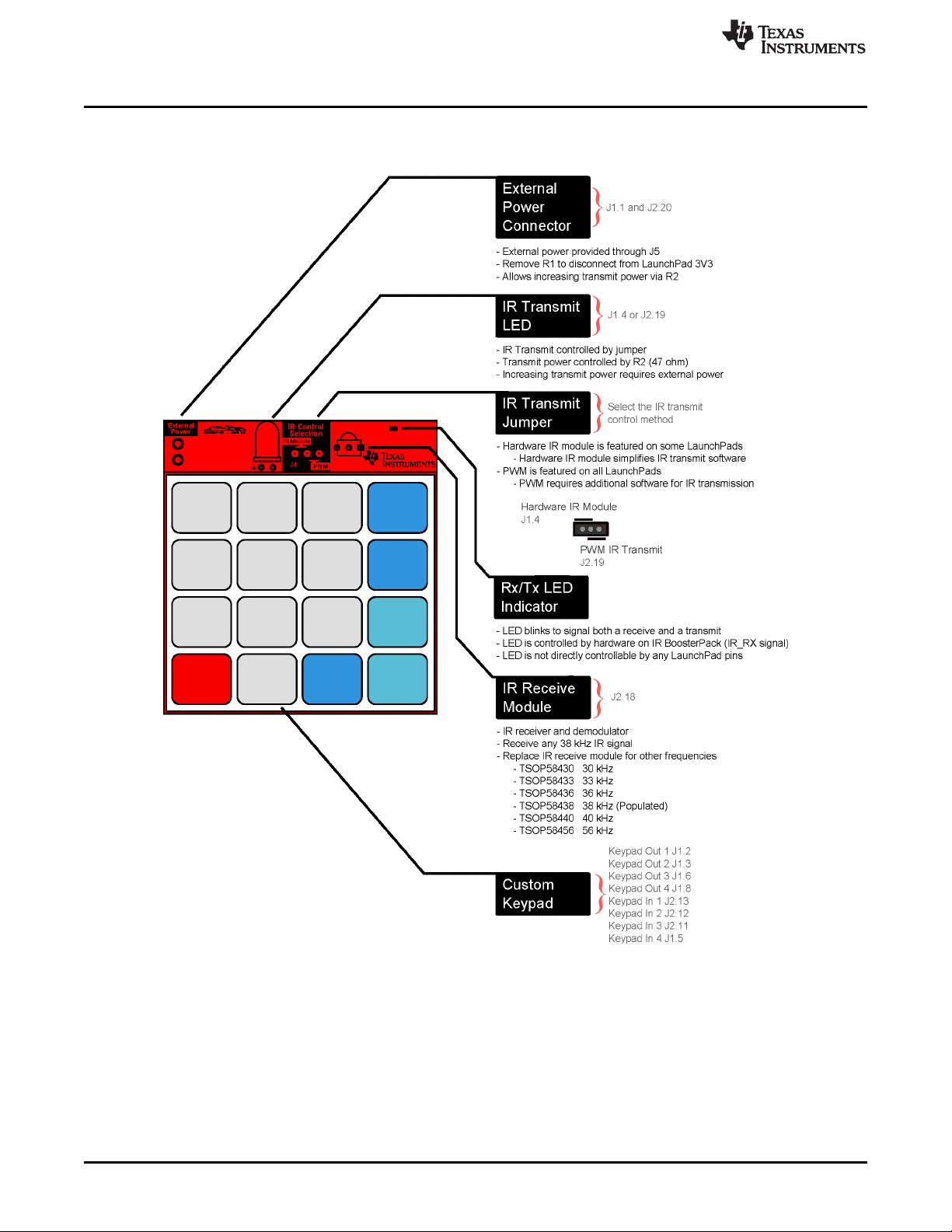
Figure 2 shows an overview of the BOOST-IR module.
www.ti.com
Figure 2. BOOST-IR Overview
4
BOOST-IR Infrared (IR) BoosterPack™ Plug-in Module SLAU598A–December 2014–Revised July 2015
Copyright © 2014–2015, Texas Instruments Incorporated
Submit Documentation Feedback
Page 5
www.ti.com
2.1 Hardware Features
2.1.1 BoosterPack Pinout
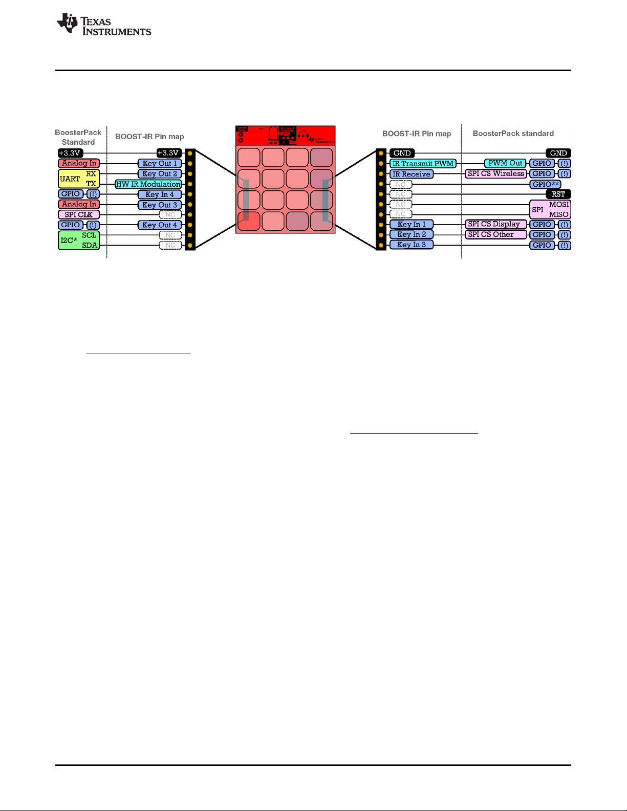
The IR BoosterPack adheres to the 20-pin LaunchPad and BoosterPack pinout standard (see Figure 3).
This standard was created to aid compatibility between LaunchPad and BoosterPack tools across the TI
ecosystem.
The 20-pin standard is compatible with the 40-pin standard that is used by other LaunchPad kits like the
MSP-EXP430F5529LP. This allows for 20-pin BoosterPacks to be used with 40-pin LaunchPads.
The BOOST-IR intentionally does not use the I2C and SPI pins to allow other BoosterPacks that use these
pins to be stacked together with the IR BoosterPack. This BoosterPack does not have both male and
female headers to support stacking on top. This is because the keypad is too large, and in most
applications this keypad would be on the top. To stack other BoosterPacks along with BOOST-IR, use
them lower in the "stack" with BOOST-IR on top.
More information about compatibility can also be found at http://www.ti.com/launchpad.
Hardware
Figure 3. BoosterPack Pinout
SLAU598A–December 2014–Revised July 2015 BOOST-IR Infrared (IR) BoosterPack™ Plug-in Module
Submit Documentation Feedback
Copyright © 2014–2015, Texas Instruments Incorporated
5
Page 6
Hardware
2.1.2 Membrane Keypad
www.ti.com
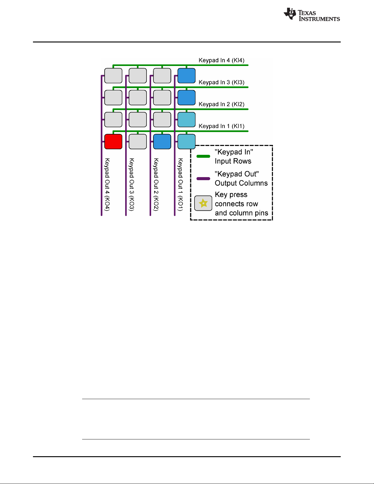
Figure 4. Membrane Keypad Connections
The membrane keypad is a 4x4 matrix keypad, controlled by 4 Keypad Out pins (columns), and 4 Keypad
In pins (rows). Without any buttons pressed, the columns and rows are not connected to each other.
When a button is pressed, it connects its corresponding column pin with its corresponding row pin.
To detect any key presses, the connection of the row pin to the column pin must be detected. This is
accomplished by configuring the Keypad Out pins as outputs, and Keypad In pins as inputs. The Keypad
Out pins are toggled high one at a time, while the Keypad In pins are read for any changes. This allows
the exact key to be determined in the 4x4 matrix.
As an example, refer to the Figure 4 keypad layout. If the bottom left button is pressed, the Keypad Out 4
pin is now connected to the Keypad In 1 pin. The host MCU starts reading the keypad matrix by toggling
Keypad Out 1 high (while keeping all other Keypad Out pins low), and reads all Keypad In pins low. This
is because Keypad Out 1 is still not connected to any Keypad In pins by a button press. The host MCU
then toggles Keypad Out 2 high, and reads all Keypad In pins still low. Eventually, the MCU toggles
Keypad Out 4 high, and reads that Keypad In 1 has now transitioned to high. Recall that the bottom left
button connects Keypad Out 4 with Keypad In 1, forcing the input row to read high. The MCU maps out
this connection and knows that the bottom left button was pushed, because that is the intersection point of
Keypad Out 4 and Keypad In 1. The MCU can now perform the action that corresponds to the key press.
It may seem like a key press can be missed with this procedure, but it is happening many times per
second, allowing for any key press to be detected. It is possible for keys to go undetected due to key
"ghosting" in a matrix keypad, but that is outside the scope of this brief overview. This only occurs when
multiple buttons are pressed at the same time, and there are ghost key detection algorithms to prevent
any misinterpretations.
NOTE: The Keypad Out 2 (J1.3) pin is connected to the UART receive pin on the BoosterPack
standard. On most 20-pin LaunchPads (MSP-EXP430G2, MSP-EXP430FR5969, MSPEXP430FR4133), the Keypad Out 2 pin is also connected to the LaunchPad backchannel
UART pin. For proper operation of the Keypad, disconnect the UART RX jumper on the
LaunchPad isolation block.
6
BOOST-IR Infrared (IR) BoosterPack™ Plug-in Module SLAU598A–December 2014–Revised July 2015
Copyright © 2014–2015, Texas Instruments Incorporated
Submit Documentation Feedback
Page 7
www.ti.com
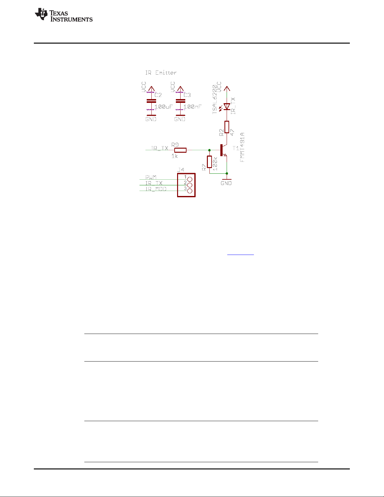
2.1.3 IR Transmit
Figure 5 shows the schematic of the IR transmit circuit.
Hardware
Figure 5. IR Transmit Circuit
2.1.3.1 IR Transmit Overview
To transmit an IR signal, an infrared (IR) LED is toggled to blink the LED. Using IR protocols, messages
can be read such as commands from remote controls. More information on IR protocol can be found in
Infrared Remote Control Implementation With MSP430FR4xx (SLAA644) and also in Section 3.1.1.
Because the IR LED requires high currents to transmit longer distances, this LED is not controlled directly
with a general purpose IO pin from the MCU. Instead a switching circuit that allows current to flow directly
from the main power source is used. See Section 2.2 for more information on power and Section 6 for the
schematics.
2.1.3.2 Setting IR Transmit Power
To set the current of the IR LED, resistor R2 (47 Ω) is used. This resistor can be adjusted to change the
IR LED transmit power. Decreasing R2 increases the power through the IR LED, which increases the
range of the remote.
NOTE: Increasing the IR transmit power may draw more current than supported from the
LaunchPad. Check the specific LaunchPad user’s guide to make sure that enough power
can be provided, or use external power (see Section 2.2.2).
2.1.3.3 IR Transmit Selection
IR transmit can be controlled by two different pins, selectable by jumper J4 (see Figure 2).
Setting the J4 jumper to the left side selects the hardware IR module (J1.4), which is only featured on
some LaunchPads, such as the MSP-EXP430FR4133. The hardware IR module simplifies the software
needed for IR transmission, because the hardware handles the protocol.
NOTE: When using the hardware IR module (J1.4), this pin is connected to the UART transmit pin
on the BoosterPack standard. On some LaunchPads, such as the MSP-EXP430FR4133, the
hardware IR module pin is also connected to the LaunchPad backchannel UART pin. For
proper operation of the hardware IR module, it is recommended to disconnect the UART TX
jumper on the LaunchPad isolation block.
SLAU598A–December 2014–Revised July 2015 BOOST-IR Infrared (IR) BoosterPack™ Plug-in Module
Submit Documentation Feedback
Copyright © 2014–2015, Texas Instruments Incorporated
7
Page 8

Hardware
Setting jumper J4 to the right selects PWM control (J2.19), which can be used on any LaunchPad. The
PWM method requires additional software to control the PWM pin according to the IR protocol.
2.1.4 IR Receive
Figure 6 shows the schematic of the IR receive circuit.
The IR receive module receives and demodulates the incoming signal. The default IR receiver supports IR
transmission at 38 kHz. This is the most commonly used IR frequency for use in remote controls. If
another frequency is needed, the IR receive module can be replaced with a drop-in replacement that
supports another frequency (see Table 1). More information on IR protocol can be found in Infrared
Remote Control Implementation With MSP430FR4xx (SLAA644) and also in Section 3.1.1.2.
www.ti.com
Figure 6. IR Receive Circuit
The IR receive module is very sensitive and receives almost all of the IR transmissions from its own IR
LED. This is mostly unavoidable without physically altering the BoosterPack. Make sure that your firmware
compensates for receiving its own transmissions by ignoring them or verifying that the proper output was
sent.
2.2 Power
The board was designed to be powered either by the attached LaunchPad or by an external source
through the external power connector.
2.2.1 LaunchPad Power
This is the default power configuration for the BOOST-IR. In this configuration, power is provided through
the 3V3 (J1.1) pin on the BoosterPack headers. The 3V3 pin powers everything on the IR BoosterPack,
including IR transmit and receive.
Table 1. IR Receiver Replacement Options
Part Number Receive Frequency
TSOP58430 30 kHz
TSOP58433 33 kHz
TSOP58436 36 kHz
TSOP58438 38 kHz (Populated)
TSOP58440 40 kHz
TSOP58456 56 kHz
8
BOOST-IR Infrared (IR) BoosterPack™ Plug-in Module SLAU598A–December 2014–Revised July 2015
Copyright © 2014–2015, Texas Instruments Incorporated
Submit Documentation Feedback
Page 9

www.ti.com
2.2.2 External Power
There are a few reasons why you may want to provide external power, including higher IR transmit power,
changing to a different voltage, or using a battery to go "wireless." To provide external power, use the
following procedure.
1. Disconnect BOOST-IR power from the LaunchPad power source
(a) Option 1: Remove the 3V3 jumper on the LaunchPad isolation block
In this case, the MCU is also powered by the external source; make sure that the voltage is within
the MCU device voltage operation specification.
(b) Option 2: Remove R1 on the BOOST-IR to completely disconnect LaunchPad and BoosterPack
power
(i) In this case, the LaunchPad must provide power to its own MCU.
(ii) If the LaunchPad and BoosterPack have different operating voltages, IR communication may
not function properly.
2. Connect the external power supply.
After these steps are complete, you should be able to operate the IR BoosterPack with an external
voltage.
2.3 Design Files
2.3.1 Hardware
Schematics can be found in Section 6. All design files including schematics, layout, bill of materials
(BOM), Gerber files, and documentation are available in a zip folder (SLAR104).
Hardware
2.3.2 Software
All design files including TI-TXT object-code firmware images, software example projects, and
documentation are available in the LaunchPad specific software folders. To see which LaunchPads
feature BOOST-IR examples, refer to the "What’s Included" section on the BOOST-IR tool folder.
2.3.3 Quick Start Guide
The BOOST-IR Quick Start Guide is SLAU614.
2.4 Hardware Change Log
PCB Revision Description
Rev 1.0 Initial Release
Table 2. Hardware Change Log
SLAU598A–December 2014–Revised July 2015 BOOST-IR Infrared (IR) BoosterPack™ Plug-in Module
Submit Documentation Feedback
Copyright © 2014–2015, Texas Instruments Incorporated
9
Page 10
TI Design and Software Examples
3 TI Design and Software Examples
3.1 TI Design: BOOST-IR + MSP-EXP430FR4133 IR Remote Control
TI Designs Design Features
TI Designs provide the foundation that you need
including methodology, testing, and design files
to quickly evaluate and customize the system. TI
Designs help you accelerate your time to market.
System Description
The BOOST-IR BoosterPack is an easy-to-use
plug-in module for adding Infrared (IR)
communications to your Launchpad design. It
contains everything that you need to start
developing IR communication with your
Launchpad, including a keypad, IR LED
transmitter, and IR receiver + demodulator.
Design Resources
TIDM-BOOST-IRREMOTE
Design Folder
MSP-EXP430FR4133 Product Folder
BOOST-IR Product Folder
MSP430FR4133 Product Folder
• Implements ASK IR modulation
• 38-kHz onboard demodulator
• 4x4 membrane keypad
• Jumper to configure IR generation method support for most LaunchPad kits
• IR Emitter and Receiver examples
• IR Learning Mode example
Featured Applications
• TV Remote Control
• Air Conditioner Remote Control
Design Photo
www.ti.com
Block Diagram
Find an answer:
MSP430 E2E Support Forum
10
BOOST-IR Infrared (IR) BoosterPack™ Plug-in Module SLAU598A–December 2014–Revised July 2015
Copyright © 2014–2015, Texas Instruments Incorporated
Submit Documentation Feedback
Page 11

(carrier modulated pulse)
logic 1
logic 1 logic 0
logic 1
carrier
logic 1
(space)
logic 0
www.ti.com
3.1.1 System Design Theory
The following sections discuss the IR modulation and demodulation schemes used in this design. For
additional information about IR remote control theory and implementing IR protocols on FR4xx devices,
see the application note Infrared Remote Control Implementation with MSP430FR4xx (SLAA644).
3.1.1.1 ASK Modulation
The MSP-EXP430FR4133 + BOOST-IR Remote Control sends and receives ASK modulated IR signals
with a 38-kHz carrier frequency. 38 kHz is one of the most common IR carrier frequencies for remote
control applications and is used by many TV and air conditioner manufacturers.
In ASK modulation, two signals (the higher-frequency carrier, and the envelope) are combined to form the
modulated signal. The envelope contains the data to be sent, under one of many different standard
encoding schemes (for example, pulse position, pulse distance, pulse width, or Manchester encoding).
The carrier is simply a high frequency signal. When the two signals are combined, the carrier frequency is
output whenever the envelope is high, and the signal is held low when the envelope is low. Figure 7
shows an example of an IR modulated signal using Pulse Position encoding.
TI Design and Software Examples
Figure 7. Pulse Position Encoding (ASK)
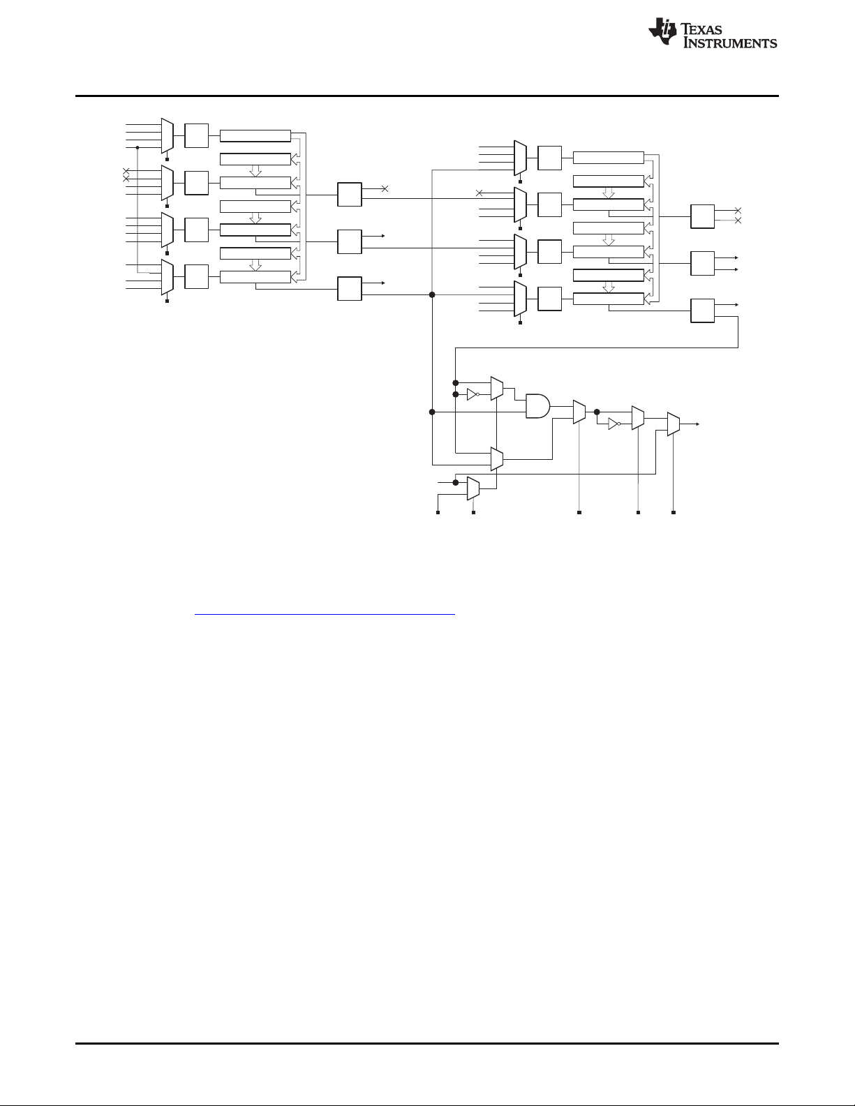
3.1.1.2 IR Modulation Logic on MSP430FR4133
The MSP430FR4133 device includes some logic to help enable IR modulation, inside of the SYS module.
This logic block allows the outputs signals from some timer modules in the device (producing the carrier
frequency) to be combined with an envelope generated by another timer module, the output of the
USCI_A0 module, or with a software controlled IRDATA line. In addition, the Timers can optionally be
cascaded. TA1 can select to use TA0 as the clock source so that TA1 is essentially counting ticks of the
TA0 PWM output signal. This arrangement allows for flexible and configurable generation of all different
kinds of ASK and FSK modulation schemes. Figure 8 shows an overview of the modules involved in
internal IR signal generation on the FR4133.
SLAU598A–December 2014–Revised July 2015 BOOST-IR Infrared (IR) BoosterPack™ Plug-in Module
Submit Documentation Feedback
Copyright © 2014–2015, Texas Instruments Incorporated
11
Page 12
00
01
10
11
Divider
TA0CLK
ACLK
SMCLK
Input
Logic
Input
Logic
00
01
10
11
DVSS
DVCC
00
01
10
11
P1.1
from RTC
DVSS
DVCC
Output
Logic
Output
Logic
P1.1
TA0CCTL1.CCIS
TA0CTL.TASSEL
TA0CCTL2.CCIS
P1.2
00
01
10
11
Divider
TA1CLK
ACLK
SMCLK
Input
Logic
Input
Logic
00
01
10
11
P1.4
DVSS
DVCC
00
01
10
11
P1.5
DVSS
DVCC
Output
Logic
Output
Logic
P1.5
TA1CCTL1.CCIS
TA1CTL.TASSEL
TA1CCTL2.CCIS
P1.4
from CapTouchIO
(INCLK)
to ADC Trigger
Timer0_A3
Timer1_A3
Comparator 1
CCR2
Comparator 2
CCR1
Comparator 0
Counter
CCR0
Comparator 1
CCR2
Comparator 2
CCR1
Comparator 0
Counter
CCR0
0
1
0
1
From UCA1TXD/UCA1SIMO
SYSCFG1.IRDATA
SYSCFG1.IRDSSEL SYSCFG1.IRPSEL
P2.6/UCA1TXD/UCA1SIMO
SYSCFG1.IRMSEL
1
0
0
1
1
0
SYSCFG1.IREN
0
1
IR Modulation (SYS)
from CapTouchIO
(TA0.1B)
(TA0.2B)
(TA1.2B)
(TA1.1B)
(TA1.2B)
(TA0.1A)
(TA0.1B)
(TA0.2A)
(TA0.2B)
(TA0.1A)
(TA0.2A)
(TA1.2A)
(TA1.1A)
(TA1.1B)
(TA1.1A)
(TA1.2A)
Output
Logic
(TA0.0B)
(TA0.0A)
Input
Logic
00
01
10
11
DVSS
DVCC
TA0CCTL0.CCIS
(TA0.0A)
(TA0.0B)
Input
Logic
00
01
10
11
DVSS
DVCC
TA1CCTL0.CCIS
(TA1.0B)
(TA1.0A)
Output
Logic
(TA1.0B)
(TA1.0A)
P1.2
INCLK
TI Design and Software Examples
www.ti.com
Figure 8. IR Modulation Logic Blocks in MSP430FR4133
Figure 9 shows the ASK IR Modulation signal generation used in the example software for this TI Design,
found in the MSP-EXP430FR4133 Software Examples. TA0CCR2 output is used as the carrier frequency,
and is ANDed with TA1CCR2 which is generating the envelope, before the final resulting signal is brought
out on the output pin.
Therefore to generate the signal, TA0CCR0 and TA0CCR2 are set once at the beginning of the code to
generate a 38-kHz PWM for the carrier signal. For each bit to be sent, the TA1CCR0 and TA1CCR2
values are updated to generate a PWM with the correct envelope timing for sending a 0 or 1 using Pulse
Distance Encoding.
12
BOOST-IR Infrared (IR) BoosterPack™ Plug-in Module SLAU598A–December 2014–Revised July 2015
Copyright © 2014–2015, Texas Instruments Incorporated
Submit Documentation Feedback
Page 13

5HFHLYHU¶V
MCU
Demodulation
TA0
CCR2
TA1
CCR2
Carrier
Envelope
Modulated
0
1
0
1
From UCA0TXD/UCA0SIMO
SYSCFG1.IRDATA
SYSCFG1.IRDSSEL SYSCFG1.IRPSEL
P1.0/UCA0TXD/UCA0SIMO
SYSCFG1.IRMSEL
1
0
0
1
1
0
SYSCFG1.IREN
0
1
IR Modulation (SYS)
www.ti.com
TI Design and Software Examples
Figure 9. ASK IR Generation on MSP430FR4133
3.1.1.3 ASK Demodulation
The receiver uses a photodiode to convert the IR light to current. A transimpedance amplifier is frequently
used to convert the current into voltage, which passes through a gain amplifier and filter before
demodulation, which removes the carrier signal. Then the demodulated signal, which is essentially just the
envelope signal now that the carrier has been removed, can be connected directly the MCU for decoding
(see Figure 10).
Figure 10. IR Demodulation
The BOOST-IR BoosterPack features a Vishay TSOP59348 IR Receiver device. This device performs all
of the steps above, stripping off the carrier signal, and then provides the envelope directly to the FR4133
TA0.2 input. The Timer A0 module is then used in capture mode to record the edges of the signal. The
pulse length is calculated from these capture values to determine if a 0 or 1 was received using pulse
distance encoding.
3.1.1.4 Pulse Distance Encoding and Protocol
The software IR emitter and receiver examples included with this TI Design use a Pulse Distance protocol
for communication between two LaunchPads + BoosterPacks. This protocol is similar to that used on
many commercially available remote control devices. In Pulse Distance Encoding, each bit is a carrier
modulated pulse and a space – the carrier modulated pulse width is constant, while the width of the space
varies to indicate a logic 0 or logic 1.
SLAU598A–December 2014–Revised July 2015 BOOST-IR Infrared (IR) BoosterPack™ Plug-in Module
Submit Documentation Feedback
Copyright © 2014–2015, Texas Instruments Incorporated
13
Page 14

9 ms
Leading Code
00 1
0
1
0
1
0
LSB MSB
ADDRESS
4.5 ms
11 01 01 0
1
LSB MSB
ADDRESS
01 1 0 11 1
0
LSB MSB
COMMAND
1
0 0
1
00
0
1
LSB MSB
COMMAND
Tail
logic 0 logic 1
(carrier modulated pulse)
(space with width A)
(carrier modulated pulse)
(space with width B)
carrier
TI Design and Software Examples
The provided IR Emitter and Receiver code uses a standard timing for remote controls using pulse
distance protocol. Logic 1 is defined as a 560-µs carrier modulated period followed by a 1690-µs space
period. Logic 0 is defined as a 560-µs carrier modulated period followed by a 560-µs space period. The
data frame starts with a Leading Code of 9-ms modulated period followed by a 4.5-ms space period.
After the Leading Code, the data payload begins. The payload consists of 4 bytes:
1. 1 address byte
2. The same address byte inverted
3. 1 command byte
4. The same command byte inverted
The address byte is used to identify the device so that receivers can ignore signals from other IR remotes
that are intended for other devices. The example code has arbitrarily chosen 0x55 for the address byte.
The command byte is the actual data that you want to send – in this example it is a byte that corresponds
to the number of the key that was pressed. The protocol follows the address byte with an inverted version
of itself, and the command byte with an inverted version of itself. This is to help catch any errors in the
communication to increase robustness, and is a standard feature of the pulse distance protocol used by
many remote controls.
After the payload is transmitted, the Data Frame ends with a tail pulse to indicate the end of the packet.
This tail is a 560 us carrier modulated pulse.
Figure 12 shows the full Data Frame Format.
www.ti.com
Figure 11. Pulse Distance Encoding
3.1.1.5 IR Learning Mode
14
Figure 12. Pulse Distance Protocol, Data Frame Format
For some applications like universal TV remotes, it is useful to have a device that can learn different IR
codes. To do this, the device needs to be able to receive an IR signal from another device, record it, and
then later be able to reproduce it on command. The MSP430FR4133 is an FRAM device, allowing for a
large amount of nonvolatile storage that can be quickly and easily accessed with no extra steps needed
(like is needed for writing Flash) . FRAM can be written just like RAM at speeds up to 8 MHz – perfect for
logging data. The FRAM also has near-infinite write cycles, so the IR codes can be reprogrammed
frequently without risk of wearing out the memory. Because of this, the device is a great candidate for
implementing IR applications that require "learning" IR codes. The example software for this TI Design
includes a Learning Mode example.
BOOST-IR Infrared (IR) BoosterPack™ Plug-in Module SLAU598A–December 2014–Revised July 2015
Copyright © 2014–2015, Texas Instruments Incorporated
Submit Documentation Feedback
Page 15

www.ti.com
The learning mode example code provided uses a Timer A capture input to receive an IR signal stripped
of its 38-kHz carrier, and records the edge timing of the signal. This timing information is stored in FRAM
for later use. Later, when the code should reproduce the same signal for TX, it simply reads the timing
information from FRAM and uses this to set the envelope Timer values for the transmission until the
transmission is complete.
In this type of application, the device does not need to decode or understand any protocol – it simply
needs to be able to reproduce the signal on command. This code therefore supports all different ASK
encoding and protocols, allowing it to be able to copy and repeat IR commands from a wide variety of
sources like consumer television remotes.
The only limits are:
• 38-kHz carrier
This is due to the frequency of the Vishay demodulator present on the BoosterPack. This part can be
replaced and the code modified if other carrier frequencies are needed.
• Quantity of FRAM available on the device compared to the length and number of codes to store
The code timing information is stored in FRAM, so the amount of available FRAM in your code
determines how many different codes, and the length of the codes, that can be learned.
3.1.2 Hardware
The MSP430FR4133 device has built-in IR modulation capabilities. The internal IR modulation is
configurable and flexible. It supports both ASK and FSK modulation, which allows implementation of a
variety of IR protocols. For more information on the IR modulation capabilities of the FR4133 device, see
the MSP430FR4xx and MSP430FR2xx Family User's Guide (SLAU445). For more information on how to
implement different remote control IR protocols using the FR4133 IR features, see the application report
Infrared Remote Control Implementation With MSP430FR4xx (SLAA644).
TI Design and Software Examples
3.1.2.1 MSP-EXP430FR4133 LaunchPad
The MSP430FR4133 device is the first device in TI’s FRAM technology platform to combine an LCD driver
and infrared modulation functions with FRAM. FRAM is a cutting edge memory technology, combining the
best features of flash and RAM into one nonvolatile memory. More information on FRAM can be found at
www.ti.com/fram.
Device features include:
• 1.8-V to 3.6-V operation
• Up to 16-MHz system clock and 8-MHz FRAM access
• 15.5KB of FRAM and 2KB of SRAM
• Ultra-low-power operation
• Low-power liquid crystal display (LCD) with LPM3.5 support
• Two timer blocks and two serial interfaces (SPI, UART, or I2C)
• RTC counter (real-time counter module) with LPM3.5 support
• Analog: 10-channel 10-bit ADC with window comparator
• Capacitive Touch I/Os on all GPIO pins (60) to enable touch applications
• Digital: CRC16
For more information on the hardware and capabilities of the MSP-EXP430FR4133 LaunchPad, see the
MSP430FR4133 LaunchPad Development Kit (MSP-EXP430FR4133) User's Guide (SLAU595).
SLAU598A–December 2014–Revised July 2015 BOOST-IR Infrared (IR) BoosterPack™ Plug-in Module
Submit Documentation Feedback
Copyright © 2014–2015, Texas Instruments Incorporated
15
Page 16

P4.7/R13
P4.6/R23
P4.5/R33
P4.4/LCDCAP1
P4.3/LCDCAP0
P4.2/XOUT
P4.1/XIN
DVSS
DVCC
TEST/SBWTCK
P4.0/TA1.1
P8.3/TA1.2
P8.2/TA1CLK
P8.1/ACLK/A9
P8.0/SMCLK/A8
P1.7/TA0.1/TDO/A7
P1.6/TA0.2/TDI/TCLK/A6
P1.5/TA0CLK/TMS/A5
P1.4/MCLK/TCK/A4/VREF+
P1.3/UCA0STE/A3
P1.2/UCA0CLK/A2
P1.0/ /A0/Veref–UCA0TXD/UCA0SIMO
P5.7/L39
P5.6/L38
P5.5/L37
P5.4/L36
P5.3/UCB0SOMI/UCB0SCL/L35
P5.2/UCB0SIMO/UCB0SDA/L34
P5.1/UCB0CLK/L33
P5.0/UCB0STE/L32
P2.7/L31
P2.6/L30
P2.5/L29
P2.4/L28
P2.3/L27
P2.2/L26
P2.1/L25
P2.0/L24
P6.7/L23
P6.6/L22
P6.5/L21
P6.4/L20
P6.3/L19
P6.2/L18
P6.1/L17
P6.0/L16
P3.7/L15
P3.6/L14
P3.5/L13
P3.4/L12
P3.3/L11
P3.2/L10
P3.1/L9
P3.0/L8
P7.7/L7
P7.6/L6
P7.5/L5
P7.4/L4
P7.3/L3
P7.2/L2
P7.1/L1
P7.0/L0
1
2
3
4
5
6
7
8
9
10
11
12
13
14
15
16
171819202122232425262728293031
32
33
34
35
36
37
38
39
40
41
42
43
44
45
46
47
48
49
50
51
52
53
54
55
56
57
58
59
60
61
62
63
64
TI Design and Software Examples
www.ti.com
Figure 13. MSP430FR4133 Pinout
16
BOOST-IR Infrared (IR) BoosterPack™ Plug-in Module SLAU598A–December 2014–Revised July 2015
Copyright © 2014–2015, Texas Instruments Incorporated
Submit Documentation Feedback
Page 17

www.ti.com
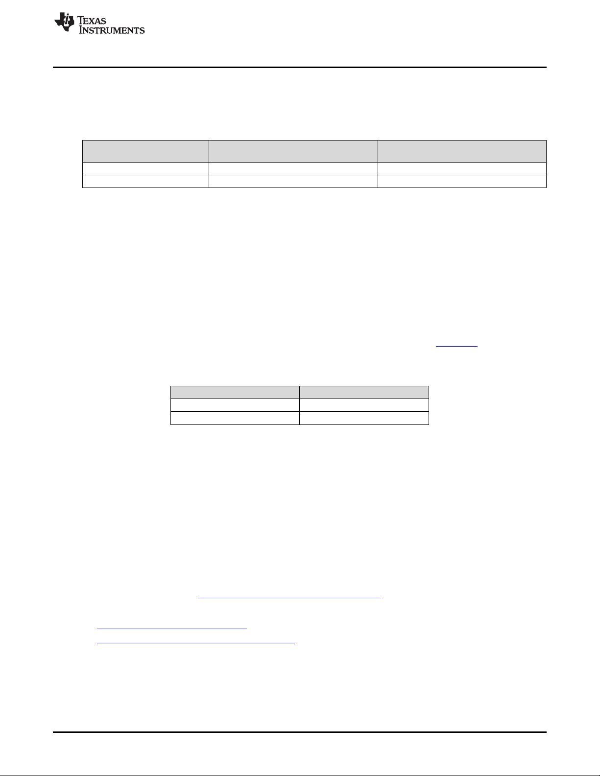
3.1.3 Software Examples
There are two BOOST-IR software examples included with the MSP-EXP430FR4133 LaunchPad (see
Table 3), which can be found in the MSP-EXP430FR4133 Software Examples.
Table 3. Software Examples
Demo Name LaunchPad Required Description More Details
IR Emitter and and BOOST-IR BoosterPack modules to communicate. One
Receiver LaunchPad is programmed with the Emitter code, and the
IR Learning Mode MSP-EXP430FR4133 the BOOST-IR BoosterPack to copy and repeat IR sequences Section 3.1.6
MSP-EXP430FR4133 Section 3.1.5
This example uses two MSP-EXP430FR4133 LaunchPad kits
other is programmed with the Receiver code.
This example uses one MSP-EXP430FR4133 LaunchPad with
from some other IR emitter (for example, a TV remote control)
3.1.4 Development Environment Requirements
To use any of the software examples with the LaunchPad, you must have an integrated development
environment (IDE) that supports the MSP430FR4133 device.
Table 4. IDE Minimum Requirements for MSP430FR4133
Code Composer Studio™ IDE IAR Embedded Workbench™ IDE
CCS v 6.1 or later IAR EW430 v7.0 or later
TI Design and Software Examples
For more details on where to download the latest IDE, see Section 4.2.
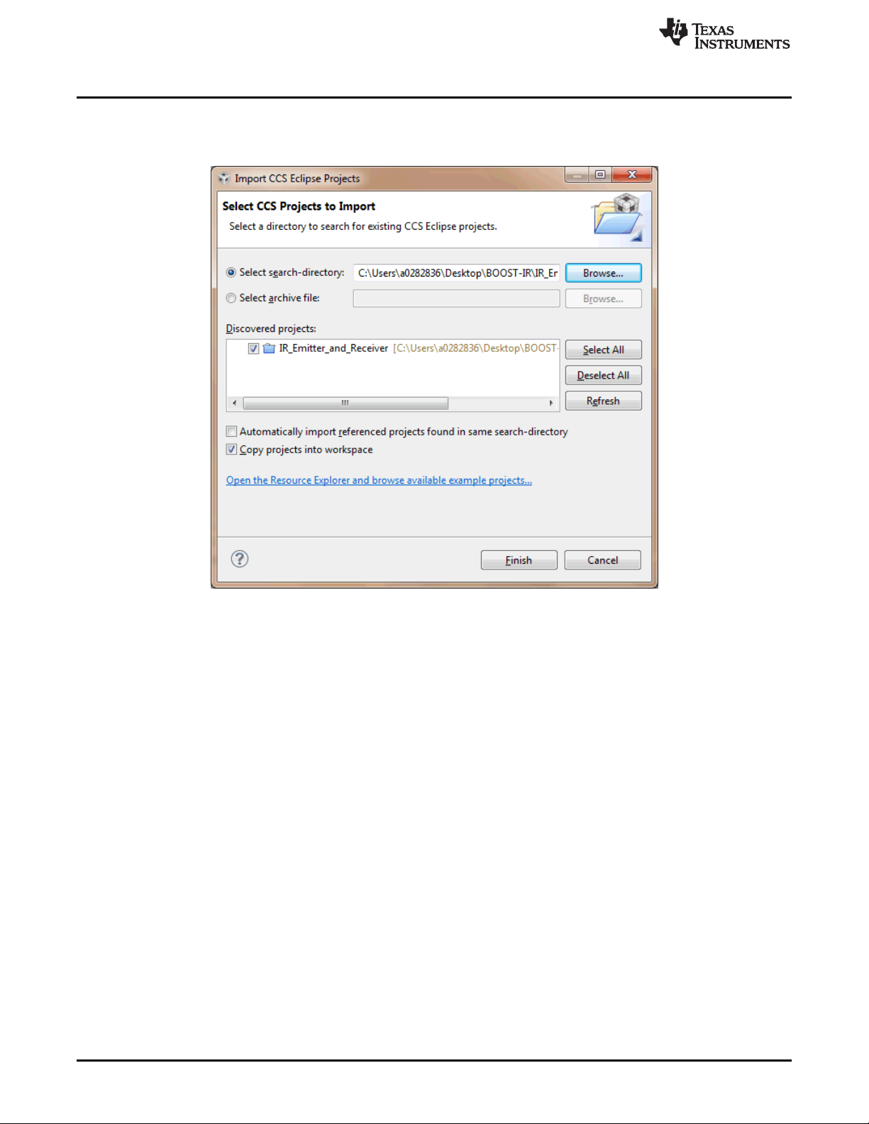
3.1.4.1 CCS
CCS 6.1 or higher is required. When CCS has been launched and a workspace directory chosen, use
Project > Import Existing CCS Eclipse Project (see Figure 14). Browse to the desired demo project
directory that contains main.c. This is IR_Emitter_and_Receiver or IR_Learning_Mode.
Figure 14. Directing the Project>Import Function to the Demo Project
Selecting the \CCS folder also works. The CCS-specific files are located there.
SLAU598A–December 2014–Revised July 2015 BOOST-IR Infrared (IR) BoosterPack™ Plug-in Module
Submit Documentation Feedback
Copyright © 2014–2015, Texas Instruments Incorporated
17
Page 18
TI Design and Software Examples
When you click OK, CCS should recognize the project and allow you to import it. The indication that CCS
has found the project is that its name is shown in the Import CCS Eclipse Projects window with a check
mark to the left of it, as shown in Figure 15.
www.ti.com
Sometimes CCS finds the project but does not show a checkmark; this might mean that your workspace
already has a project by that name. You can resolve this by renaming or deleting that project. (Even if you
do not see it in the CCS workspace, be sure to check the workspace’s directory on the file system.)
Make sure to check Copy projects into workspace, then click Finish to complete the import process. For
the IR Emitter and Receiver project, note that the project contains two separate pieces of code – one for
programming the device for transmit and one for programming the device to receive. This is handled
within one project by using build configurations. To change between Emitter and Receiver, right-click on
the CCS project and go to Build Configurations > Set Active and then select either IR Emitter or IR
Receiver.
3.1.4.2 IAR
IAR 6.10.2 or higher is required. To open the demo in IAR, click File>Open>Workspace…, and browse to
the *.eww workspace file inside the \IAR folder of the desired demo. All workspace information is
contained within this file.
The \IAR folder also has an *.ewp project file. This file can be opened into an existing workspace by
clicking Project>Add-Existing-Project….
Although the software examples have all of the code required to run them, IAR users may download and
install MSP430Ware, which contains MSP430™ libraries and the TI Resource Explorer. These are already
included in a CCS installation (unless the user selected otherwise).
Figure 15. When CCS Has Found the Project
18
BOOST-IR Infrared (IR) BoosterPack™ Plug-in Module SLAU598A–December 2014–Revised July 2015
Copyright © 2014–2015, Texas Instruments Incorporated
Submit Documentation Feedback
Page 19

www.ti.com
3.1.5 IR Emitter and Receiver Software Example
This code shows how to send and receive IR signals using the BOOST-IR BoosterPack. The example
requires two sets of MSP-EXP430FR4133 LaunchPad kits and BOOST-IR BoosterPack modules to
communicate with each other.
3.1.5.1 Source File Structure
This project is organized in multiple files. This makes it easier to navigate and reuse parts of it for other
projects. Table 5 describes each file in the project.
Table 5. Source Files and Folders
Name Description
FR4133_IR_BP_RX.c IR receiver main function, IR setup and processing, and other functions
FR4133_IR_BP_TX.c IR emitter main function, IR setup and processing, and other functions
HAL_FR4133LP_Board.c Board initialization functions, keypad scanning functions
HAL_FR4133LP_LCD.c LCD initialization functions, LCD display functions
3.1.5.2 IR Emitter Example
The IR Emitter code sends messages to the other board. Whenever a button is pressed on the
BoosterPack, a command corresponding to the key pressed is sent to the other board. You can tell that
the IR emitter code is loaded into the BoosterPack because the LCD radio symbol and TX are displayed.
An LED is lit when the transmission is happening. The button that is pressed is also displayed on the LCD.
This example makes use of the IR features of the MSP430FR4133 device for generating an ASK
modulated signal. TA1CCR2 generates the envelope for the data to be sent, and TA0CCR2 generates the
carrier frequency. The timers are connected internally and using the SYSCFG settings are combined to
generate the IR signal output on a pin, which goes to the IR emitter LED on the BoosterPack. For more
details on the IR generation using the IR modulation features of the MSP430FR4133, and information on
how data is encoded in the examples, see Section 3.1.1.
TI Design and Software Examples
3.1.5.3 IR Receiver Example
The IR Receiver code receives messages from the emitter board. Whenever a signal is received from the
other board (i.e. when a button on the keypad is pressed on the other BoosterPack), and the Receiver
BoosterPack receives the signal, the name of the button pressed is displayed on the LaunchPad LCD. For
example, if the button POWER is pressed on the emitter BoosterPack, and the signal is received by the
receiver BoosterPack, "POWER" is displayed on the receiver LaunchPad LCD and the LED on P4.0
blinks.
This example uses the IR receiver and demodulator on the BoosterPack to strip the carrier off of the
received signal. This means that the signal into the MSP430 is just the envelope signal. The timer capture
registers are used to measure the high and low pulses to decode the data. For more details on the IR
demodulation and decode using the BoosterPack hardware and the timers of the MSP430FR4133, and for
information on how data is encoded in the examples, see Section 3.1.1.
SLAU598A–December 2014–Revised July 2015 BOOST-IR Infrared (IR) BoosterPack™ Plug-in Module
Submit Documentation Feedback
Copyright © 2014–2015, Texas Instruments Incorporated
19
Page 20

TI Design and Software Examples
3.1.6 IR Learning Mode Software Example
The Learning Mode example can receive IR sequences from a remote control or other device and store
them in memory associated with different buttons on the BoosterPack keypad. Then the sequences can
be transmitted from the BoosterPack by pushing the keypad buttons, and used to control IR devices.
3.1.6.1 Source File Structure
This project is organized in multiple files. This makes it easier to navigate and reuse parts of it for other
projects. Table 6 describes each file in the project.
Table 6. Source Files and Folders
Name Description
FR4133_IR_BP_Learn.c IR Learning mode main function, IR setup and processing, and other functions
HAL_FR4133LP_Learn_Board.c Board initialization functions, keypad scanning functions
HAL_FR4133LP_LCD.c LCD initialization functions, LCD display functions
3.1.6.2 IR Learning Mode Example
When the COPY button is pressed, the firmware enters learning mode. Push the button on the keypad
that you want to train, and then transmit the signal to be learned from a device like a TV remote. Continue
this until all desired buttons are assigned, and then press OK to return to normal transmit mode. Now,
when a button is pressed, the stored signal is transmitted.
While receiving signals in learning mode, the MSP430FR4133 device uses the timer capture function to
record the time between signal edges for the high and low pulses. The sequence of pulse lengths is
stored in FRAM for later use to generate the same signal when the button is pressed. For more details
about how the learning mode software works, see Section 3.1.1.5.
Note that the IR receiver and demodulator on the BoosterPack is tuned for 38-kHz carrier frequency. This
is one of the most common carrier frequencies used by many remote control manufacturers for a number
of devices. If communication needs to be with a device that uses a different carrier (for example, 40 kHz),
this component can be replaced with a different receiver and demodulator device.
www.ti.com
3.1.7 Testing
3.1.7.1 Test Environment
For current measurements
Test instrument: Fluke 87, set to µA measurement
Voltage supply at 3.3 V applied to MSP-EXP430FR4133 3V3 and GND pins on J6 of LaunchPad. All
jumpers on LaunchPad J101 removed to exclude the eZ-FET from the measurement. JP1 for LED is also
removed to remove the indicator LED (not transmission LED) from the measurement as well.
For range measurements
Measured with two MSP-EXP430FR4133 + BOOST-IR, one programmed as Emitter, and one
programmed as Receiver. Environment was a normal home/office environment with normal ambient
overhead white fluorescent lighting and with no obstructions between the LaunchPads. Distance was
increased until the Receiver LaunchPad no longer received correct codes from Transmitter LaunchPad.
Range was tested with two different resistor values to show the impact of the resistor size on IR signal
strength. Changing this resistor is described in Section 2.1.3.2.
20
BOOST-IR Infrared (IR) BoosterPack™ Plug-in Module SLAU598A–December 2014–Revised July 2015
Copyright © 2014–2015, Texas Instruments Incorporated
Submit Documentation Feedback
Page 21
www.ti.com
3.1.7.2 Test Data
Table 7 shows current measurements both with and without the BOOST-IR module connected to the
board. This is to show the contribution of just the MSP430 versus the consumption of the whole system.
TI Design and Software Examples
Table 7. Current Consumption
Software
IR Emitter 830 µA 4.0 µA
IR Receiver 1059 µA 238 µA
Idle Current With BOOST-IR Idle Current
(No Buttons Pressed) (MSP-EXP430FR4133 Only)
Current consumption when the BOOST-IR module is present is much higher due to the consumption of
the IR demodulator TSOP58238 module. The TSOP58238 module on its own consumes approximately
800 µA, so it makes up the bulk of the current consumption of the system. For product designs where IR
RX function is not needed, only TX, this device could be eliminated and a lower current consumption in
idle mode more like the MSP-EXP430FR4133 current for IR Emitter shown above could be achieved.
Note that while sending a transmission by pressing a button, the current peaks – this peak current
depends on the R value that you have selected for R2 (which also affects range as detailed below).
The current consumption for IR Receiver mode of just the MSP-EXP430FR4133 was measured at
approximately 238 µA. This is higher than the IR Emitter code, because while the IR Emitter code can
remain in LPM3 until a button is pressed, the IR Receiver must have the timer capture set up with the
timer module sourced from the high-frequency SMCLK to have a high enough timer resolution to decode
the signals. To keep SMCLK enabled while idle, IR Emitter code can only enter LPM0, because this is the
lowest power mode in which SMCLK is on. See the MSP430FR4133 data sheet (SLAS865) for more
details about low-power modes (LPMs) and current consumption.
Table 8. Range Testing
Resistor Used for R2 (Ω) Range (meters)
47 8 m
4.7 20 m
By default, the BOOST-IR module comes with a 47-Ω resistor for R2. R2 controls the TX current for the IR
LED. This has a direct effect on the brightness of the IR LED and therefore the range of transmission that
is possible. When testing with the TX and RX code examples, the maximum range for transmitting from
one BOOST-IR to the other was 8 meters with the default 47-Ω R2 – at longer distances, transmission and
reception became unreliable. When the value of R2 was changed to 4.7 Ω, the LED is driven with more
current and able to transmit much farther. In our test, we achieved a 20-meter transmission distance with
this resistor. Using a smaller R2 allows for longer transmission distances at the expense of increased
current consumption. For transmission power this high, external power must be provided, because the
MSP-EXP430FR4133 and other LaunchPads are unable to provide this much power directly. In a
production design, experimentation should be used to help determine the best resistor value to achieve
the desired transmission range while still fitting within the design’s power budget.
3.1.8 Design Files
For software files, see the MSP-EXP430FR4133 Software Examples
For hardware files, see:
• BOOST-IR Hardware Design Files and Section 2 and Section 6.
• MSP-EXP430FR4133 Hardware Design Files
SLAU598A–December 2014–Revised July 2015 BOOST-IR Infrared (IR) BoosterPack™ Plug-in Module
Submit Documentation Feedback
Copyright © 2014–2015, Texas Instruments Incorporated
21
Page 22

Additional Resources
4 Additional Resources
4.1 TI LaunchPad Portal
More information about LaunchPad kits, supported BoosterPack modules, and available resources can be
found at:
• TI’s LaunchPad portal: information about all LaunchPad kits from TI for all MCUs
4.2 Download CCS, IAR, or Energia
Although the files can be viewed with any text editor, more can be done with the projects if they’re opened
with a development environment like Code Composer Studio™ (CCS), IAR, or Energia.
4.3 MSP430Ware and TI Resource Explorer
MSP430Ware is a complete collection of libraries and tools. It includes a driver library (driverlib), graphics
library (grlib), and many other software tools. MSP430Ware is optionally included in a CCS installation or
can be downloaded separately. IAR users must download it separately.
MSP430Ware includes the TI Resource Explorer, for easily browsing tools. For example, Figure 16 shows
all the software examples in the tree. Inside TI Resource Explorer, these examples and many more can be
found and easily imported into CCS with one click.
www.ti.com
22
Figure 16. BOOST-IR Software Examples in TI Resource Explorer
BOOST-IR Infrared (IR) BoosterPack™ Plug-in Module SLAU598A–December 2014–Revised July 2015
Copyright © 2014–2015, Texas Instruments Incorporated
Submit Documentation Feedback
Page 23

www.ti.com
4.4 The Community
4.4.1 TI E2E™ Community
Search the forums at http://e2e.ti.com. If you cannot find your answer, post your question to the
community.
4.4.2 Community at Large
Many online communities are dedicated to the LaunchPad and BoosterPack ecosystem – for example,
http://www.43oh.com. You can find additional tools, resources, and support from these communities.
5 FAQs
Q: Why does one column on my keypad not work?
A: On some LaunchPads, one of the column pins is connected to the UART RX pin through the
backchannel UART. Disconnect the UART RX jumper on the LaunchPad isolation block.
Q: Why do I receive everything that I transmit?
A: The receiver module is sensitive, and receives almost every transmission sent by the IR LED. Make
sure that your firmware ignores the messages that you send.
Additional Resources
SLAU598A–December 2014–Revised July 2015 BOOST-IR Infrared (IR) BoosterPack™ Plug-in Module
Submit Documentation Feedback
Copyright © 2014–2015, Texas Instruments Incorporated
23
Page 24

11
12
13
14
15
16
17
18
19
20
10
9
8
7
6
5
4
3
2
1
1
2
3
4
5
6
7
8
1
2
3
1
2
GND
OUT
VS
Schematics
6 Schematics
Hardware design files can be downloaded from www.ti.com/lit/zip/slar104.
www.ti.com
24
Figure 17. Schematics
BOOST-IR Infrared (IR) BoosterPack™ Plug-in Module SLAU598A–December 2014–Revised July 2015
Copyright © 2014–2015, Texas Instruments Incorporated
Submit Documentation Feedback
Page 25

www.ti.com
Revision History
Revision History
Changes from December 5, 2014 to July 20, 2015 .......................................................................................................... Page
• Throughout document, changed the link destinations for the MSP-EXP430FR4133 Software Examples and MSP-
EXP430FR4133 Hardware Design Files............................................................................................... 1
NOTE: Page numbers for previous revisions may differ from page numbers in the current version.
SLAU598A–December 2014–Revised July 2015 Revision History
Submit Documentation Feedback
Copyright © 2014–2015, Texas Instruments Incorporated
25
Page 26

IMPORTANT NOTICE
Texas Instruments Incorporated and its subsidiaries (TI) reserve the right to make corrections, enhancements, improvements and other
changes to its semiconductor products and services per JESD46, latest issue, and to discontinue any product or service per JESD48, latest
issue. Buyers should obtain the latest relevant information before placing orders and should verify that such information is current and
complete. All semiconductor products (also referred to herein as “components”) are sold subject to TI’s terms and conditions of sale
supplied at the time of order acknowledgment.
TI warrants performance of its components to the specifications applicable at the time of sale, in accordance with the warranty in TI’s terms
and conditions of sale of semiconductor products. Testing and other quality control techniques are used to the extent TI deems necessary
to support this warranty. Except where mandated by applicable law, testing of all parameters of each component is not necessarily
performed.
TI assumes no liability for applications assistance or the design of Buyers’ products. Buyers are responsible for their products and
applications using TI components. To minimize the risks associated with Buyers’ products and applications, Buyers should provide
adequate design and operating safeguards.
TI does not warrant or represent that any license, either express or implied, is granted under any patent right, copyright, mask work right, or
other intellectual property right relating to any combination, machine, or process in which TI components or services are used. Information
published by TI regarding third-party products or services does not constitute a license to use such products or services or a warranty or
endorsement thereof. Use of such information may require a license from a third party under the patents or other intellectual property of the
third party, or a license from TI under the patents or other intellectual property of TI.
Reproduction of significant portions of TI information in TI data books or data sheets is permissible only if reproduction is without alteration
and is accompanied by all associated warranties, conditions, limitations, and notices. TI is not responsible or liable for such altered
documentation. Information of third parties may be subject to additional restrictions.
Resale of TI components or services with statements different from or beyond the parameters stated by TI for that component or service
voids all express and any implied warranties for the associated TI component or service and is an unfair and deceptive business practice.
TI is not responsible or liable for any such statements.
Buyer acknowledges and agrees that it is solely responsible for compliance with all legal, regulatory and safety-related requirements
concerning its products, and any use of TI components in its applications, notwithstanding any applications-related information or support
that may be provided by TI. Buyer represents and agrees that it has all the necessary expertise to create and implement safeguards which
anticipate dangerous consequences of failures, monitor failures and their consequences, lessen the likelihood of failures that might cause
harm and take appropriate remedial actions. Buyer will fully indemnify TI and its representatives against any damages arising out of the use
of any TI components in safety-critical applications.
In some cases, TI components may be promoted specifically to facilitate safety-related applications. With such components, TI’s goal is to
help enable customers to design and create their own end-product solutions that meet applicable functional safety standards and
requirements. Nonetheless, such components are subject to these terms.
No TI components are authorized for use in FDA Class III (or similar life-critical medical equipment) unless authorized officers of the parties
have executed a special agreement specifically governing such use.
Only those TI components which TI has specifically designated as military grade or “enhanced plastic” are designed and intended for use in
military/aerospace applications or environments. Buyer acknowledges and agrees that any military or aerospace use of TI components
which have not been so designated is solely at the Buyer's risk, and that Buyer is solely responsible for compliance with all legal and
regulatory requirements in connection with such use.
TI has specifically designated certain components as meeting ISO/TS16949 requirements, mainly for automotive use. In any case of use of
non-designated products, TI will not be responsible for any failure to meet ISO/TS16949.
Products Applications
Audio www.ti.com/audio Automotive and Transportation www.ti.com/automotive
Amplifiers amplifier.ti.com Communications and Telecom www.ti.com/communications
Data Converters dataconverter.ti.com Computers and Peripherals www.ti.com/computers
DLP® Products www.dlp.com Consumer Electronics www.ti.com/consumer-apps
DSP dsp.ti.com Energy and Lighting www.ti.com/energy
Clocks and Timers www.ti.com/clocks Industrial www.ti.com/industrial
Interface interface.ti.com Medical www.ti.com/medical
Logic logic.ti.com Security www.ti.com/security
Power Mgmt power.ti.com Space, Avionics and Defense www.ti.com/space-avionics-defense
Microcontrollers microcontroller.ti.com Video and Imaging www.ti.com/video
RFID www.ti-rfid.com
OMAP Applications Processors www.ti.com/omap TI E2E Community e2e.ti.com
Wireless Connectivity www.ti.com/wirelessconnectivity
Mailing Address: Texas Instruments, Post Office Box 655303, Dallas, Texas 75265
Copyright © 2015, Texas Instruments Incorporated
Page 27

Mouser Electronics
Authorized Distributor
Click to View Pricing, Inventory, Delivery & Lifecycle Information:
Texas Instruments:
BOOST-IR
 Loading...