

Page 1
I NDUSTRIAL SENSORS &CONTROLS
20413, 20600, 20650 SERIES
Snap-Action
Automatic and Manual reset
Fixed Temperature Thermostats
Key Features
• Klixon snap-action bimetal disc assures positive
make/break action.
• Available with surface, thru-wall,well or cavity-type mountings
• Temperature setting factory calibrated to your
specifications
• High capacity – up to 30 amps at 120, 240, and 277 VAC
resistive.
• Extra high capacity – up to 40 amps at 120 and 240 VAC
resistive
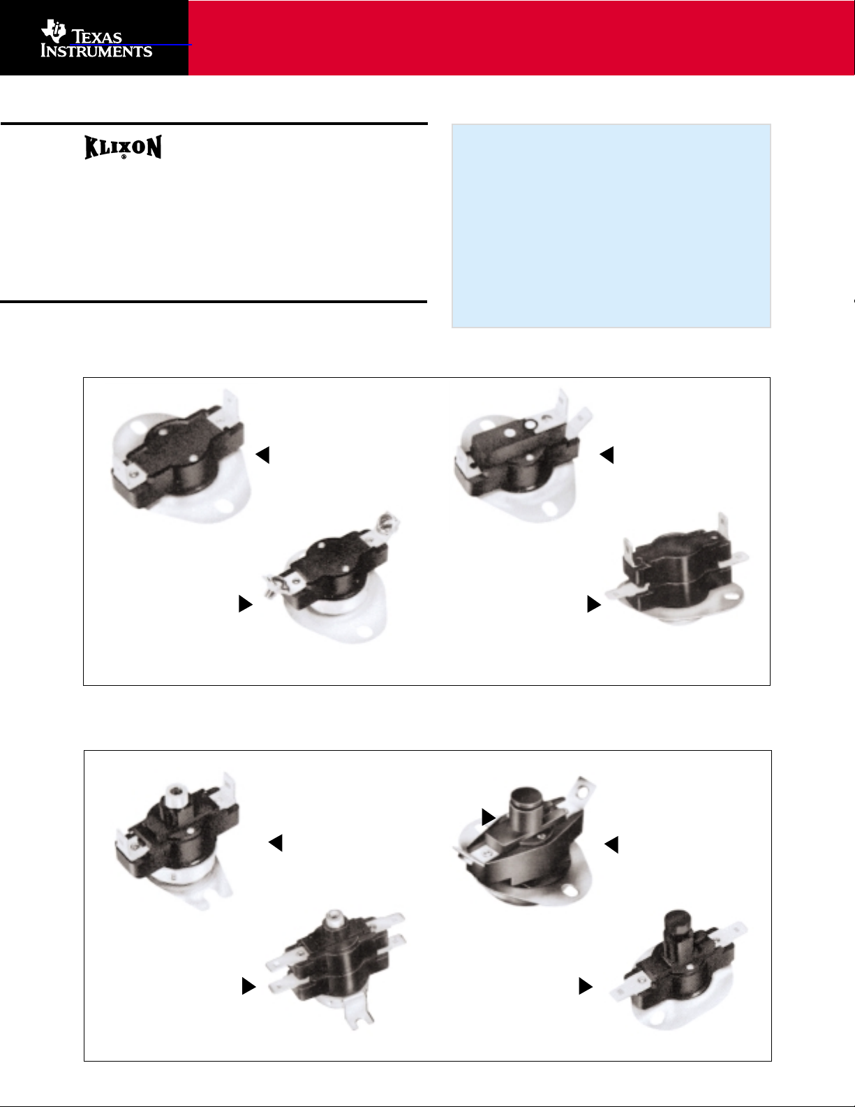
Automatic reset Standard Constructions
Manual Reset Standard Constructions
Single-Pole, Double-Throw
20600D
Small Oval Top Flange
Double-Pole, Single-Throw
20650
Small Oval Top Flange
Single-Pole, Single-Throw
20601 / 04 / 06 F or L
Small Oval Top Flange
Single-Pole, Single-Throw
20603 / 05 F or L
Small Oval Top Flange
Manual Override
20611 / 12 / 16L
Special Oval Bottom Flange
Manual Override
20650
Integral Surface Flange
Trip Free
20413
Small Oval Top Flange
Trip Free
20615 / 19L
Small Oval Top Flange
查询20413供应商
Page 2

Description
Klixon® thermostats have been in
production for over 50 years. The
20413, 20600, and 20650 series
thermostats are especially designed
ed for applications where space,
capacity and ease of assembly are
important production factors. They
are fixed-setting, snap-acting, automatic or manual reset temperature
controls that are ideal for such
applications as: air conditioners,
heating and ventilating equipment,
vending machines, dryers, unit
heaters, tabletop appliances, etc.
All automatic series are available as
limit switches (open on temperature rise) or fdan switches (close
on temperature rise). Switch action
is SPST, SPDT, or DPST with automatice reset types. Manual reset is
available as a limit switch in SPST
construction only.
The switch mechanism is actuated
by the Klixon snap-action, bimetal
disc which may be enclosed or
exposed. Enclosed disc devices are
particularly recommended for applications in which dust and lint are
prevalent in the environment.
Exposed disc types are used in
applications where a faster thermal
response to radiant heat is needed.
Contact parts are enclosed for both
disc types for protection against
contamination.
Mountings and Terminals
A variety of terminals and mounting
flanges are available to meet installation requirements of most
applications.
Flanges can be used for surface or
thru-wall mountings; or, thermostats
can be supplied without flanges for
well or cavity-type mountings.
Flange rotations are specified by
looking down on the terminals and
rotating the flange 30o, 45o, or
90oCW or CCW.
Flanges Available
• Small oval bottom flange
• Integral surface flange
• No flange cup
• 3/4” deep cup
• Special oval bottom flange
Electrical connections to the ther-
mostat must be tight; otherwise,
resistance in a loose connection may
cause sufficient temperature rise to
affect the performance of the thermostat or damage the terminals or
the lead wire insulation.
Terminals Available
Quick connects are available in siver
flash or plain brass.
• 1/4”Quick connects 0o, 30o, 45o,
90oterminals are male spade type
.250” x .032” thick.
• Strap terminals for electric heating
• Brass screw terminals 0o, 45
o
When screw terminals are specified,
washer head screws are supplied
unassembled. Assembled washer
head screws are available at extra
cost. Standard screw terminals have
8-32 NC-2 threads.
Temperaturre Settings,
Tolerances and Nominal
Differentials
Standard Tolerances
The ranges of temperature settings,
tolerances, and nominal differentials shown below are available.
Differential is the difference
between opening and closing temperature in oF. For example, a
thermostat which opens at 180oF
and closes at 140oF has a 40
o
differential. (Lowest unit prices are
achieved by selecting differentials
in the 30oF to 59oF range). For
temperature settings and differentials other than those shown,
please consult Marketing.
Manual Reset
Construction
There are two basic manual reset
constructions:
1) Manual Override – contracts can
be closed at any time after
device has actuated by depressing reset button.
2) Trip-Free – contacts will remain
open after device has actuated
until bimetal disc resets, even if
reset button is depressed.
Agency Recognition
Klixon 206 Series Thermostats are
recognized by UL and CSA. Please
consult Marketing for international
approvals.
UL Electrical Group
File No. E9977
U.S. Guide No. XAPX2
Canada Guide NO. XAPX8
HC&R Group
File NO. MP986
U.S. Guide No. MBPR2
Canada Guide No. MBRR8
For further information write or call:
Texas Instruments Incorporated
Commercial Sensors & Controls
Thermal Controls Marketing
34 Forest Street, MS 23-10
Attleboro, MA 02703-0964
Phone: (508) 236-3192
(508) 236-1894
Fax; (508) 236-2349
or visit our website @: www.tisensors.com
Highest
Temperature
Setting
o
F
Nominal
Differential
o
F
Standard
Tolerances
Open Close
o
F
10 to 14*
15 to 29
30 to 59
60 to 150
10 to 29*
30 to 39
40 to 59
60 to 150
20 to 29
30 to 39
40 to 59
60 to 150
30 to 39
40 to 59
60 to 150
30 to 39
40 to 59
60 to 150
-10 to 80
81 to 200
201 to 250
251 to 300
301 to 350
**
±5
±6
±6
±7
±5
±5
±5
±6
±5
±5
±6
±7
±6
±7
±8
±7
±8
±9
±5
±6
±7
±8
±5
±6
±7
±8
±6
±7
±8
±9
±8
±10
±11
±10
±12
±13
• Available in SPST construction only.
SPDT thermostats must have 15ominimum differentials.
**20413 series – up to 300
o
20600 series – up to 350
o
20650 / 54 series – up to 300o; minimum
differential 30o.
Ambient Temperature
-40oF to +350oF
-40oC to +177oC
Page 3

Underwriters’ Laboratories Electrical Current Ratings
Standard Configurations
Important Notice: Texas Instruments (TI) reserves
the right to make any changes to or to discontinue
any product or service identified in the publication
without notice. TI advises its customers to obtain
the latest version of the relevant information to
verify, before placing orders, that the information
being relied upon is current.
Texas Instruments assumes no responsibility for
infringement of patents or rights of others based
on Texas Instruments applications assistance or
product specifications since TI does not possess
full access concerning the use or application of
customer products. Texas Instruments also
assumes no responsibility for customers’ product
designs.
6,000
6,000
100,000
30,000
30,000
100,000
30,000
100,000
100,000
100,000
100,000
100,000
6,000
6,000
6,000
6,000
6,000
100,000
30,000
30,000
6,000
6,000
6,000
Number
Cycles
Contacts
Device
Amps
Res
FLA
LRA
Pilot
Duty
120 V
240 V
1-3
1-3
1-2
1-3
1-2
1-3
1-3
1-3
1-3
1-3
1-3
1-3
1-3
1-3
1-3
1-3
1-3
1-3, 4-5
1-3
4-5
1-3
4-5
5-2
277 V
480 V
800 mV
DC
Amps
Res
FLA
LRA
Pilot
Duty
Amps
Res
FLA
LRA
Pilot
Duty
Amps
Res
FLA
LRA
Pilot
Duty
20413 MR
20613
20600D
20601F, L
(appliance)
20601 (HVAC)
20602F or L
20603/5
20604F, L
20606F, L
20611L MR
20612 MTR
20616 MR
20615L MRTF
20619L MRTF
20650F, L
20650F, L, H
20650H
48
48
10
25
10
25
25
16.6
40
25
25
16.6
25
25
25
25
16
16
5.8
16
5.8
10
16
16.6
35
10
10
10
10
10
10
16
96
96
34.8
84
34.8
60
84
88
110
60
60
60
60
60
60
84
480
480
125
672
270
480
672
480
125
880
480
125
480
125
480
480
480
480
672
48
48
5
25
5
25
25
8.3
40
25
25
8.3
25
25
25
25
25
23
5
8
8
2.9
12
4.2
5
12
8.3
35
5
5
5
5
5
5
12
7
7
5.8
48
48
17.4
60
17.4
30
60
49.8
110
30
30
30
30
30
30
60
42
42
39.8
690
690
125
960
270
480
960
690
1760
380
480
480
480
480
480
960
670
670
556
22
5
22
7.2
35
22
7.2
25
22
23
23
8
8
7.2
30
8
8
23
23
42
42
43.2
95
42
42
100
88
775
125
775
1630
1760
775
690
690
775
1855
1633
48
48
13
20
13
13
5
9
5
5
30
30
10
30
690
690
960
320
400
X
X
20413L
20600D
20601L, F
20602L, F
20603L, F
20604L, F
20605L, F
20606L, F
20611L
20612L
20615L
20616L
20619L
20650L, F
MR-TF
SPDT
SPST
SPST
SPST
SPST
SPST
SPST
MR
MR
MR-TF
MR
MR-TF
DPST
High
High
High
mVdc
Extra High
High
Extra High
Pilot Duty
High
mVdc
High
Pilot Duty
High
High
Ag
Ag
Ag
Au
AgCdO
Ag
AgCdO
Ag Ribbed
Ag
Au
Ag
Ag Ribbed
Ag
Ag
3/8”
1/8”
1/8”
1/8”
1/8”
1/4”
1/4”
1/8”
1/8”
1/8”
1/8”
1/8”
1/4”
1/8”
1/2”
1/4”
1/4”
1/4”
1/4”
3/8”
3/8”
1/4”
1/4”
1/4”
1/4”
1/4”
3/8”
1/4”
Model
Switch
Type
Capacity
Contacts
Clearance
Thru
Air
Over
Surface
Page 4

20413 Series Standard Constructions
20650 Series Standard Constructions
Small Oval Top Flange @ 90
o
Exposed Disc
45oScrew terminals
Small Oval Bottom Flange @ 90
o
Enclosed Disc
45oScrew Terminals
Small Oval Top Flange @ 45o CCW
Enclosed Disc
45o Screw Terminals
.063
(1.60)
1.563
(39.70)
.063
(1.60)
90
o
.172
(4.37)
#10-24 NC-2 THD
(2 PLACES)
2.235 MAX
(56.77)
1.500
(38.10)
EXPOSED DISC
.350
(8.89)
1.18 MAX
(29.97)
1.575 MAX
(39.97)
2.00
(50.80)
.063
(1.60)
1.563
(39.70)
.063
(1.60)
90
o
.172
(4.37)
#10-24 NC-2 THD
(2 PLACES)
2.235 MAX
(56.77)
1.500
(38.10)
ENCLOSED DISC
1.215 MAX
(30.86)
1.545 MAX
(39.24)
2.00
(50.80)
ENCLOSED DISC
1.215 MAX
(30.86)
2.235 MAX
(56.77)
.381
(9.68)
#10-24 NC-2 THD
(2 PLACES)
1.563
(39.70)
.063
(1.60)
1.500
(38.10)
.063
(1.60)
90
o
2.00
(50.80)
1.545 MAX
(39.24)
DPST Automatic Reset
SPST Plus SPDT Automatic Reset
DPST Manual Reset
11/64” (4.3656) (2-PL.)
1/16” (1.588)
90o±5
o
PARTNO.
2”
(50.8)
1 9/16”
(39.687)
1/16” (1.588)
STD. .250 (6.35) x .032
(0.787) THICK SPADE
TYPE QUICK CONNECT
TERMINAL (MATES WITH
ANY STD. A.M.P. OR
ARK-LES FEMALE TERM.)
(4-PL)
2.416 ±.046
(61.37) ±(1.168)
1.555 MAX (39.497)
.350 (8.89) ±.015 (0.381)
.920 ±.010 DIA
(23.368) ±(0.254)
.723 MAX (18.364)
ENCLOSED DISC
1 1/2” (38.10)
90o±3
o
1/16” (1.588)
PARTNO.
1/16” (1.588)
2”
(50.8)
1 9/16”
(39.687)
1/4” (6.35) Q.C. TERMS
(5 PLS)
11/64” (4.366)
(2 PLS)
2.416 ±.046
(61.37) ±(1.168)
.723 MAX (18.364)
EXPOSED DISC
1 1/2” (38.10)
1.980 MAX
(50.292)
90o±5
o
1 9/16”
(39.687)
11/64” (4.366)
(2 PLS)
.723 MAX (18.364)
ENCLOSED DISC
2.416 ±.046
(61.37) ±(1.168)
1.750 MAX
(44.45)
.933 ±.010
(23.698) ±(0.254)
.093 ±.005
(2.363) ±(0.127)
.093 ±.005
(2.363) ±(0.127)
.415 ±.005
(10.54) ±(0.127)
1/4” (6.35) Q.C. TERM
(4 PLS)
Page 5

20600 Series Preferred Physical Construction
Other Physical Constructions
1.797 (45.64) MAX
20601 / 04 / 08 F or L Small Oval Top Flange at 90
o
1/4” Quick Connect Terminals
Exposed Disc
Enclosed Disc
.062 (1.57)
.172
(4.37)
90o±5
o
PARTNO.
DATECODE
2.000
(50.80)
.172
(4.37)
.062 (1.57)
1.563
(39.70)
1.105
(28.07) MAX
1.797 (45.64) MAX
.
937 (23.80) DIA MAX
1.500 (38.10)
.381 (19.68)
.
937 (23.80) DIA MAX
1.500 (38.10)
1.074
(27.28) MAX
.350 (8.89)
20601 / 04
No Flange Cup
Thru-Wall Mounting
Forked Terminals
20600D
Single-Pole, Double-Throw
Small Oval Top Flange
at 90oRotation
Quick-Connect Terminals
20601 / 04 / 06 / 08
Small Oval Bottom Flange
at 90oRotation
Quick-Connect Terminals
20601 / 04
Small Oval Flange
3/4” Depth Cup
Quick-Connect Terminals
20611 / 20616 / L
Manual Reset, Manual Override
Integral Flange, Surface Mounting
Quick-Connect Terminals
20615L / 206619L
Special Oval Bottom Flange
Manual reset, Trip Free, Surface Mounting
45oScrew Terminals
STANDARD .250 WIDE x .032 THICK
SPADE TYPE Q.C. TERMINAL AT 45
o
L MAX = 3.25 (82.55)
L MIN = 1.0 (25.40)
±.005 (.13)
.187 (.475)
.38 (9.65)
TYP
A MAX = 2.8 (71.12)
A MIN = .6 (15.24)
1.030 MAX
(26.16)
.350 (8.89)
H MAX = 2.8 (71.12)
A MIN = .6 (15.24)
EXPOSED DISC
.937 DIA MAX
(23.80)
±.005 (.13)
1.000 DIA (25.4)
STANDARD .250
WIDE x .032 THICK
SPADE TYPE QUICK
CONNECT TERMINAL
MATES WITH ANY
STANDARD AMP OR
ARK-LES FEMALE
TERMINAL
(3 TERMINALS)
STANDARD .250 WIDE x .032 THICK SPADE TYPE
QUICK-CONNECT TERMINAL (MATES WITH ANY
STANDARD AMP OR ARK-LES FEMALE TERMINAL).
.172
(4.37)
.062 (1.57)
1.563
(39.70)
2.00
(50.80)
.312
(7.92)
.062 (1.57)
.500 (12.7) R
(2 PLACES)
.172 (4.37)
2.336 (59.33)
.615 (15.62)
.013
(.33)
1.484
(37.69)
.381 (9.68)
1.563
(39.70)
1.080
(27.43)
.707
(17.96)
.062 (1.57)
1.563
(39.70)
2.00
(50.80)
.312
(7.92)
.062 (1.57)
.172
(4.37)
.500 (12.7) R
(2 PLACES)
1.563
(39.70)
.
796 (20.22)
.020
(.51)
1.797 (45.64)
.707 (17.69)
1.105
(28.07)
1.500 (38.1)
.937 DIA MAX (23.80)
1.500 (38.1)
.937 DIA MAX (23.80)
STANDARD .250 WIDE
x .032 THICK SPADE TYPE
QUICK-CONNECT
TERMINAL MATES WITH
ANY STANDARD AMP
OR ARK-LES FEMALE
TERMINAL (2 PLACES)
STANDARD .250 WIDE x .032 THICK SPADE TYPE
QUICK-CONNECT TERMINAL (MATES WITH ANY
STANDARD AMP OR ARK-LES FEMALE TERMINAL).
1.797
(45.64)
PART NO.
DATE CODE
.172
(4.37)
TEMP
CODE
1.567
MAX
(39.80)
1.885 MAX
(47.88)
1.662 MAX
(42.21)
.755 MAX
(19.69)
.937 MAX (23.80)
.792 MAX
(20.120
1.508 MAX (38.30)
.937 DIA MAX (23.80)
.172 (4.37)
90o±5
o
.031 (.79) R
±.005 (.13)
(4 PLACES)
.415 (10.54) ±.005 (.13)
.172
(4.37)
.415 (10.54) ±.005 (.13)
1.563
(39.70)
.093 (2.36) ±.005 (.13)
.093 (2.36) ±.005 (.13)
1.250
(31.75)
.381 (9.68) ±.015 (.38)
2.336 (59.33)
±.046 (1.67)
.062 (1.57)
TRAVEL OF PUSHBUTTON
TO RESET
.937 MAX
(23.80)
2.235 MAX
(56.77)
1.175 MAX
(29.85)
.170 (4.32)
(2 PLACES
.090 (2.29) R
(4 PLACES)
1.570
(39.88)
.785
(19.34)
1.380
(35.05)
1.75
(44.45)
.490
(12.47)
.980
(24.87)
Page 6

MCGS011A
Printed in U.S.A.
Reprinted 4/2002
To facilitate processing your request, please fax this page to our Product Specialists.
From ________________________________________________________
Company_____________________________________________________
Address______________________________________________________
Phone _____________________
Fax _______________________
To: Marketing Dept.
Texas Instruments
Attleboro, MA 02703
Phone:
(508) 236-3192
(508) 236-1894
(508) 236-2349
Fax:
The following information will help us determine the correct thermostat design for your application. You
may refer to the charts on pages 2 and 3 for assistance.
Request: Pricing _____________________________ Application Assistance _________________________
Description of Application ______________________________________________________________________
Estimated Annual Usage _______________________________________________________________________
Automatic Reset_______ MR________ MR-TF________ SPST________ SPDT________ DPST________
Open Temperature ____________________________ Maximum Tolerance ___________________________
Close Temperature ___________________________ Maximum Tolersnce ___________________________
Temperature Exposures: Maximum __________________________ Minimum _________________________
Location With Respect to Heat Source ___________________________________________________________
Temperature Transfer Medium (air, metal surface, etc.)_____________________________________________
Type of Heat Source: Convection _____________ Conduction ____________ Radiation ____________
Electrical Requirements: __________________ Amps @ _________________ Volts; AC or DC ___________
Resistive ___________________ Inductive ___________________* Capacitive ___________________*
Tungsten Filament __________________ Milliamp _________________ Pilot Duty _________________
*If inductive or capacitive, indicate power factor __________________________________________________
(If available, please send copy of electrical / plumbing diagram).
Switch Termination (type and angle)_____________________________________________________________
Flange (type and angle of rotation) ______________________________________________________________
Enclosed or Exposed Disc ______________________________________________________________________
Environment (dust, lint, chemical fumes, etc.) ____________________________________________________
_____________________________________________________________________________________________
Agency Approvals _____________________________________________________________________________
 Loading...