

Page 1

Series 2000 LF Antenna Design Guide
Application Note
11-06-21-068, March 2003
Radio Frequency Identification Systems
Page 2

Page 3

Lit Number: 11-06-21-068
Contents
Contents................................................................................................................................ i
Edition 1 – March 2003 ........................................................................................................ i
About this Manual................................................................................................................ii
Abstract................................................................................................................................ 1
1 Why Custom Antennas may be Required.................................................................... 2
2 Standard Antennas........................................................................................................ 3
2.1 27 µH Inductance Antennas...................................................................................... 3
2.2 47 µH Inductance Antenna........................................................................................ 4
2.3 116 µH Inductance Antenna...................................................................................... 5
3 Fine Tuning Antennas................................................................................................... 5
3.1 Tuning to Resonance @ 134.2 kHz........................................................................... 5
3.1.1 The RFM-104B Module ......................................................................................................6
3.1.2 RFM-003B and RFM-007B Modules ..................................................................................7
3.1.3 The RFM-008B Tuning Board.............................................................................................7
3.1.4 The STU-MRD1 MicroReader. ...........................................................................................8
4 Antenna Design ............................................................................................................. 8
4.1 Determining Self Inductance ..................................................................................... 9
4.1.1 By Calculation .....................................................................................................................9
4.1.2 By Measurement...............................................................................................................10
4.2 Antenna Q............................................................................................................... 11
4.2.1 Determing the Antenna’s Q Value ....................................................................................12
4.2.1.1 By Measurement........................................................................................................................ 12
4.2.1.2 By Calculation ............................................................................................................................ 12
4.3 Controlling the Antenna’s Q .................................................................................... 13
4.3.1 Wire Selection...................................................................................................................13
4.3.1.1 Skin Effect.................................................................................................................................. 13
4.3.1.2 Litze Wire ................................................................................................................................... 14
4.3.1.3 Other Wires Used in Antenna Construction ............................................................................... 15
4.4 Antenna Size........................................................................................................... 16
4.4.1 Antenna Size vs. Inductance ............................................................................................17
4.4.2 Adapting a non 27µH Antenna .........................................................................................18
4.4.2.1 Using External Capacitance....................................................................................................... 18
4.5 Antenna Tails.......................................................................................................... 21
4.5.1 Tail Construction ...............................................................................................................21
4.6 Ferrite Cored Antennas........................................................................................... 22
5 Other Antennas ........................................................................................................... 22
5.1 Field Lines .............................................................................................................. 22
5.2 Opposing Antennas (In-Phase) ............................................................................... 23
5.3 Opposing Antennas (out-of-phase) ......................................................................... 24
5.4 Noise Canceling Antennas..................................................................................... 26
Appendix A – MicroReader Antenna Designs.................................................................. 27
Appendix B. Contacts........................................................................................................ 32
Figure 1.
Figures
Standard Antennas............................................................................................. 3
Page 4

Lit Number: 11-06-21-068
Figure 2. MicroReader Antenna (47 µH)............................................................................ 4
Figure 3. Mini-RFM Antenna (116 µH) ............................................................................... 5
Figure 4. The RFM-104B RF Module.................................................................................. 6
Figure 5. Inductance Fine-Tuning ..................................................................................... 6
Figure 6. RFM-003B and RFM-007B Modules ................................................................... 7
Figure 7. Capacitance Fine-Tuning................................................................................... 7
Figure 8. RFM-008B RF Module and ACC-008A Tuning Board ....................................... 8
Figure 9. The MicroReader ................................................................................................ 8
Figure 10. “ADU.EXE” Screen.......................................................................................... 10
Figure 11. LCR Meter ........................................................................................................ 10
Figure 12. High Q Vs. Low Q ............................................................................................ 11
Figure 13. LF System Spectrum....................................................................................... 11
Figure 14. Spectrum Analyzer Screen ............................................................................. 12
Figure 15. Litze Wire (3 sizes) .......................................................................................... 14
Figure 16. ‘Jumbo’ Oxygen Free Hi-Fi Wire..................................................................... 15
Figure 17. Road Loop Wire............................................................................................... 15
Figure 18. Transformer Wire ............................................................................................ 16
Figure 19. Reading Range Reduction due to Noise........................................................ 16
Figure 20. Windings Vs. Inductance ................................................................................ 17
Figure 21. Single Loop Vs. 27 µH Inductance ................................................................. 17
Figure 22. Out of Tune Conditions................................................................................... 18
Figure 23. Polypropylene Capacitor De-rating................................................................ 20
Figure 24. Polypropylene capacitors (0.01 µF & 0.47 µF)............................................... 20
Figure 25. Antenna Tail Construction.............................................................................. 21
Figure 26. Ferrite Cored Antenna..................................................................................... 22
Figure 27. Field Lines ....................................................................................................... 23
Figure 28. Antenna Field patterns.................................................................................... 23
Figure 29. Opposing Antennas (In-phase)....................................................................... 24
Figure 30. Two 54 µH Antennas Connected in Parallel (In-Phase) ................................ 24
Figure 31. Opposing Antennas (out-of-phase)............................................................... 25
Figure 32. Two 54 µH Antennas connected in Parallel (out-of-phase) .......................... 25
Figure 33. Noise Canceling Antenna ............................................................................... 26
Figure 34. MicroReader Antenna 1 .................................................................................. 28
Figure 35. MicroReader Antenna 2 .................................................................................. 28
Figure 36. MicroReader Antenna 3 .................................................................................. 29
Figure 37. MicroReader Antenna 4 .................................................................................. 30
Tables
Table 1.
RF Module Antenna Characteristics.................................................................. 9
Table 2. External Capacitance Values ............................................................................. 19
Table 3. MicroReader Antenna Designs.......................................................................... 27
Page 5

Lit Number: 11-06-21-068
Edition 1 – March 2003
This is the first edition of this LF Antenna Design Guide
It contains details on how to develop custom antennas for use with the following
products:
RFM-003B, RFM-104B, RFM-007B, RFM-008B RF Modules and the MicroReader
(Note: The S2510 reader incorporates the RFM-007B)
This document has been created to help support Texas Instruments’
Customers in designing in and /or using TI*RFID products for their
chosen application. Texas Instruments does not warrant that its
products will be suitable for the application and it is the responsibility of
the Customer to ensure that these products meet their needs, including
conformance to any relevant regulatory requirements.
Texas Instruments (TI) reserves the right to make changes to its
products or services or to discontinue any product or service at any time
without notice. TI provides customer assistance in various technical
areas, but does not have full access to data concerning the use and
applications of customers’ products.
Therefore, TI assumes no liability and is not responsible for Customer
applications or product or software design or performance relating to
systems or applications incorporating TI products. In addition, TI
assumes no liability and is not responsible for infringement of patents
and / or any other intellectual or industrial property rights of third parties,
which may result from assistance provided by TI.
TI products are not designed, intended, authorized or warranted to be
suitable for life support applications or any other life critical applications
which could involve potential risk of death, personal injury or severe
property or environmental damage.
TIRIS and TI*RFID logos, the words TI*RFID™ and Tag-it™ are trademarks or
registered trademarks of Texas Instruments Incorporated (TI).
Copyright (C) 2001 Texas Instruments Incorporated (TI)
This document may be downloaded onto a computer, stored and duplicated as
necessary to support the use of the related TI products. Any other type of duplication,
circulation or storage on data carriers in any manner not authorized by TI represents a
violation of the applicable copyright laws and shall be prosecuted.
Page (i)
Page 6
Lit Number: 11-06-21-068
PREFACE
Read This First
About this Manual
This LF Antenna Design Guide Application Note (11-06-21-068} is written for the
sole use by TI*RFID Customers who are engineers experienced with TI*RFID and
Radio Frequency Identification Devices (RFID).
Regulatory and safety notes that need to be followed are given Section XX.
Conventions
Certain conventions are used in order to display important information in this manual,
these conventions are:
WARNING:
A warning is used where care must be taken or a certain
procedure must be followed, in order to prevent injury or
harm to your health.
CAUTION:
This indicates information on conditions, which must be met,
or a procedure, which must be followed, which if not heeded
could cause permanent damage to the system.
Note:
Indicates conditions, which must be met, or procedures, which
must be followed, to ensure proper functioning of any hardware or
software.
Information:
Indicates conditions, which must be met, or procedures, which
must be followed, to ensure proper functioning of any hardware or
software.
If You Need Assistance
For more information, please contact the sales office or distributor nearest you. This
contact information can be found on our web site at: http://www.ti-rfid.com
Page (ii)
.
Page 7

J.A.Goulbourne
This document describes how to design and develop custom antennas suitable
for attaching to Texas Instruments’ Low Frequency (LF) Radio Frequency (RF)
modules and readers. It looks at the matching circuits of the standard RFMs
and details the antenna requirements for each one.
The issues of reader inductance and Q are examined, together with wire
selection, tail construction and the use of external capacitance in bringing an
antenna to resonance.
Lit Number 11-03-21-004
LF Antenna Design Guide
Abstract
Page (1)
Page 8
1 Why Custom Antennas may be Required
There are many reasons why custom built antennas may be required:
• special sized antennas are needed
• the antennas have to be built into structures/ equipment e.g. doors
• very large antenna are required e.g. road loops
• small antennas are needed (for localized reading).
• the antenna is for the microreader
A further reason may be to get increased read distance but the reader antenna
is just one factor amongst many that dictates reading distance. In order of
importance these factors are:
• The size and shape of the transponder’s antenna.
Lit Number: 11-06-21-068
• The size and shape of the reader’s antenna
• The electrical noise in the environment
• The transmitter power (limited by legislation)
• Metal in the environment
Warning:
Increasing the antenna size doesn’t automatically lead to an
increase in a tag’s reading performance – it may reduce.
The tag’s signal must always be 6 dB stronger than any
electrical noise to ensure a successful read.
As an reader’s antenna size increases, more ambient noise
is picked up and a tag may have to move closer to the
antenna to make sure its signal is still the strongest.
Result – shorter reading distance
Texas Instrument’ antennas are optimized and, size for size, a custom antenna design
is unlikely to give a greater read range.
Page (2)
Page 9
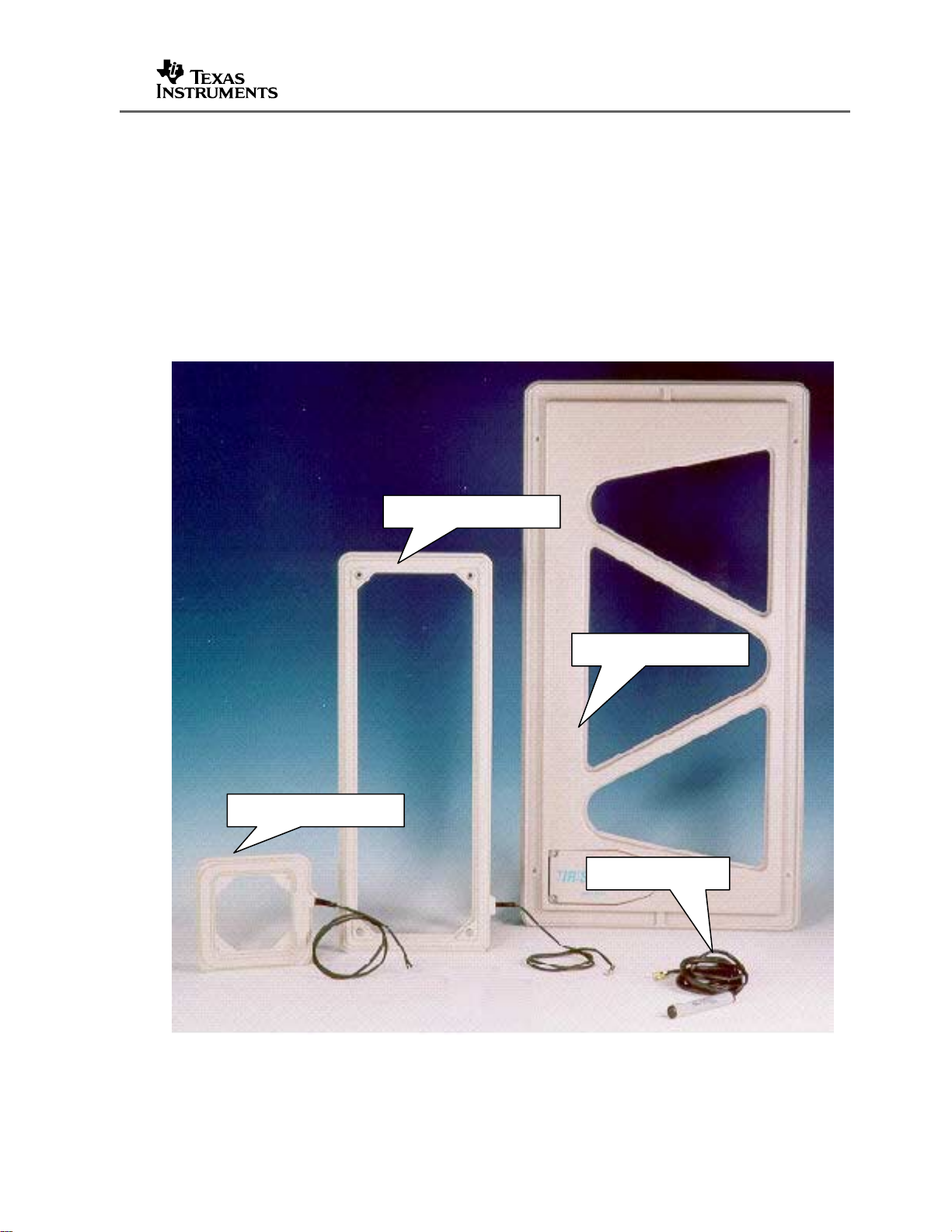
2 Standard Antennas
Because different RF Modules require antennas with different inductances, Texas
Instruments have three categories of antennas available:
2.1 27 µH Inductance Antennas
These antennas are used with the RFM-104B, RFM-007B and RFM-008B RF
modules.
RI-ANT-G02E
Lit Number: 11-06-21-068
RI-ANT-G04E
RI-ANT-G02E
RI-ANT-S02C
Figure 1. Standard Antennas
Page (3)
Page 10

The RI-ANT-G01E, RI-ANT-G02E antennas have 1m tails and are nominally 27 µH
and when connected to the appropriate RF Module can be tuned to resonate at 134.2
kHz. The RI-ANT-G04C antenna is provided with no tail and is nominally 26 µH. If
2.5 mm
2
(14 SWG) wire is used, a 4m (12’) tail can be added and still be capable of
being tuned to resonance.
Information:
The antenna tail is an integral part of the RF Module’s matching
circuit. Changing the length of the tail changes the performance.
This topic is dealt with in a later section
2.2 47 µH Inductance Antenna
The MicroReader requires an antenna with a self inductance of 47 µH. The following
antenna is available:
Lit Number: 11-06-21-068
Figure 2. MicroReader Antenna (47 µH)
RE-LNA-DLXK-NO
Page (4)
Page 11
2.3 116 µH Inductance Antenna
The RFM-003B module requires an antenna with a self inductance of 116 µH and the
following antenna is available:
RI-ANT-P02A
Lit Number: 11-06-21-068
Figure 3. Mini-RFM Antenna (116 µH)
Historically, the Mini-RF Module was intended for hand-held readers and so the
antenna is supplied with a 100 mm (5”) tails.
3 Fine Tuning Antennas.
The antenna and feed cable are all part of an LC antenna matching circuit on Series
2000 readers. Changing any part has an impact on the total system, e.g. lengthening
the feeder cable. Each module requires antennas of a certain Inductance to ensure
the matching circuit is correct and, because of manufacturing tolerances, each
antenna must be fine tuned in its final positions before a system is commissioned,.
Each module has provision for this tuning.
3.1 Tuning to Resonance @ 134.2 kHz
Texas Instrument’s LF RFID system operates at 134.2 kHz and any antenna must be
fine-tuned to resonate at that frequency for optimum performance.
1
ƒ
(134.2 kHz)
=
2
π LC
Page (5)
[1]
Page 12
Equation [1] is the formula that determines at what frequency the antenna circuit
(L)
(L)
resonates and you can see how either the Capacitance (C) or the Inductance (L) can
be varied to arrive at the required frequency (ƒ). Some RF modules tune to resonance
by varying the capacitance, whilst the RFM-104B and the Remote Antenna Tuning
Boards both vary the inductance.
3.1.1 The RFM-104B Module
The RFM-104B (standard) RF module is shown in Figure 4
Lit Number: 11-06-21-068
Figure 4. The RFM-104B RF Module
RFM-104B modules use a variable inductor to fine tune antennas. A representation of
the circuit is shown in Figure 5.
Capacitance (C)
Antenna
Inductance
Variable
Inductor
Variable
Inductance
Figure 5. Inductance Fine-Tuning
Page (6)
Page 13

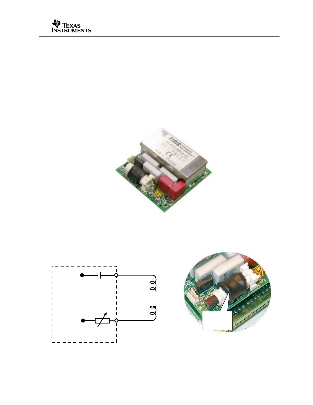
3.1.2 RFM-003B and RFM-007B Modules
The RFM-003B (Mini-RFM) and the RFM-007B (Power RFM) are shown in Figure 6
Figure 6. RFM-003B and RFM-007B Modules
Lit Number: 11-06-21-068
The RFM-003B and RFM-007B modules both use capacitance tuning (using jumpers)
for the fine tuning. This circuit is represented in Figure 7.
Capacitance (C)
Antenna
Inductance (L)
Capacitance
Jumpers
Figure 7. Capacitance Fine-Tuning
3.1.3 The RFM-008B Tuning Board
The RFM-008B (Remote Antenna) Module’s resonant components have been taken
off the RF Module and attached to a separate tuning board. In this way it is possible
to have cable runs of up to 120 m (400’) between the RF Module and the tuning board.
Page (7)
Page 14

Lit Number: 11-06-21-068
Figure 8. RFM-008B RF Module and ACC-008A Tuning Board
The board has a wide range of capacitance, which can be selected using on-board
jumpers. This arrangement allows for antennas with inductances from 12 to 80 µH to
be connected and fine tuned by a variable inductor.
3.1.4 The STU-MRD1 MicroReader.
This reader is shown in Figure 9.
Figure 9. The MicroReader
Unlike the other RF modules already described which need high Q antennas for
optimum performance; the MicroReader is designed for low Q antennas. Antenna Q
is described in more detail in later sections but in general, low Q antennas are more
tolerant of miss-tuning and the presence of metal. If MicroReader antennas have an
inductance close to 47 µH, then fine tuning is rarely necessary.
4 Antenna Design
Making antennas for S2000 Series readers is straight-forward. Only two
characteristics need to be controlled - Inductance and antenna Q
Page (8)
Page 15

Lit Number: 11-06-21-068
For an antenna to function correctly with a particular RF Module, the parameters must
match those in Table 1
RF Module
RI-RFM-104B 27 26 ~ 28 100
RI-RFM-007B 27 25.5 ~ 28.5 100
RI-ACC-008B 27 12 ~ 80 60 ~ 120
RI-STU-MRD1 47 46 ~ 48 20
RI-RFM-003B 116 115 ~ 117 200
RI-STU-S251B 27 26 ~ 27.9 100
Table 1. RF Module Antenna Characteristics
Inductance
4.1 Determining Self Inductance
The unit of measurement for inductance is the Henry (H). The values for Series 2000
antennas are in the micro-Henry (µH) range
(µH)
Inductance
Range (µH)
Q
4.1.1 By Calculation
For S2000 Series readers, antenna inductance can be calculated using the software
utility “ADU.exe” (Antenna Design Utility). This program is available from your local
Texas Instruments RFID representative and is shown in Figure 10.
Note:
Because of the different characteristics of various wire types,
some experience with this program is required. By modelling and
then constructing different sized loops, you can determine what
offsets are required for the wire you are using, to get the exact
inductance
Page (9)
Page 16

Figure 10. “ADU.EXE” Screen
Lit Number: 11-06-21-068
.
The length and width of an antenna and the wire size can be specified and by
adjusting the number of windings (or the size) you can decide what size antenna will
give you the correct inductance.
4.1.2 By Measurement
Relatively low cost LCR (Inductance, Capacitance and Resistance) meters are
available that will measure the inductance of a loop accurately enough for our
purposes.
Figure 11. LCR Meter
Page (10)
Page 17

These meters normally measure the inductance at 1 kHz (not 134.2 kHz) but providing
y
that the meter has a resolution of 0.1 µH, they can be used
4.2 Antenna Q
The Q value of an antenna is a measure of the efficiency. For the same input power,
high Q antennas have a much greater RF output than lower Q antennas.
Lit Number: 11-06-21-068
High " Q"
Low "Q"
ƒ
0
Frequenc
Figure 12. High Q Vs. Low Q
A high Q antenna also serves as a filter ignoring signals outside its bandwidth but high
Q antennas are more effected by the presence of metal than low Q ones.
REF .0 DBM MARKER 134 400.0 H
10 DB/DIV RANGE .0 DBM -20.1 DBM
60 dB
CENTRE 134 400.0 H SPAN 200 000.0
RBW 1 KHZ VBW 3 KHZ ST .4 SEC
B = 12 kHz
Figure 13. LF System Spectrum
Page (11)
Page 18

Which is why the MicroReader, which was designed for applications such as vehicle
immobilizer systems (where the antenna is around the lock barrel) and hotel door
locks, requires low Q antennas.
4.2.1 Determing the Antenna’s Q Value
4.2.1.1 By Measurement
Q values are normally measured using a signal generator and a spectrum analyzer. A
signal is fed into the antenna circuit and the peak amplitude of the resulting output is
detected by a spectrum analyzer.[ƒ
frequency of the input signal is then raised until a 3 dB drop in the amplitude of the
spectrum analyzer signal is detected [ƒ
reduced until the signal is at the -3 dB point on the low side [ƒ
[2] the Q can be determined
] (this should be around 134.2 kHz). The
0
Lit Number: 11-06-21-068
]. The frequency of the input signal is then
2
]. Then using formula
1
Figure 14. Spectrum Analyzer Screen
4.2.1.2 By Calculation
This is method depends on the accurate measure of the series resistance of the
antenna but even when read by an LCR meter will give an adequate approximate
value.
Q =
ƒ
ƒ
0
ƒ1 - ƒ
-3dB
1
ƒ
0
2
ƒ
[2]
2
Q =
2
ƒL
π
[3]
R
Page (12)
Page 19

Example 1. RI-ANT-G01E antenna,
Where:
ƒ = 134200 Hz (134.2 kHz)
L = 0.000027 H (27 µH)
R = 0.2 Ohms
Lit Number: 11-06-21-068
Q = (2 * 3.142 * 134200 * 0.000027)/ 0.2 = 114
Example 2. MicroReader antenna,
Where:
ƒ = 134200 Hz (134.2 kHz)
L = 0.000047 H (47 µH)
R = 2.4 Ohms
Q = (2 * 3.142 * 134200 * 0.000027)/ 2.4 = 16.5
4.3 Controlling the Antenna’s Q
We have seen from Equation [3] that the resistance (R) controls the Q. When R is
low, an antenna has a high Q and when R is high, the Q is low.
By selecting the correct wire type we can vary the Q.
4.3.1 Wire Selection.
At RF frequencies, the behavior of an AC current through a wire is different from the
flow through a DC circuit. What might be considered a low resistance wire in a DC
circuit can become high impedance when in an AC circuit because of the ‘Skin Effect’.
4.3.1.1 Skin Effect
At RF frequencies e.g. 134 kHz, when a signal passes through a wire, eddy currents at
the centre of the wire inhibit flow and the current tends to flow close to the
circumference (skin) of the wire. This is the ‘Skin Effect’ and the higher the frequency,
the thinner the depth of the skin through which the current flows.
So, at 134.2 kHz, we get a skin depth of:
Depth = 2 / (sq root (134200/1000)) = 0.173 mm (0.007”)
Skin depth(mm) =
Page (13)
2
ƒ
1000
[4]
Page 20

4.3.1.2 Litze Wire
Because a low resistance is required for high Q antennas, Texas Instruments use
Litze Wire in their antennas. Litze wire uses multiple (e.g. 120) individually insulated
(lacquered) wire stands, covered in silk to make up the wire. As each strand is twice
the skin depth, total current flow occurs in each strand and for a particular wire size,
eddy currents are eliminated. Result – low impedance wire and, because there is only
a thin silk outer layer, multiple windings are kept as close together as possible.
Lit Number: 11-06-21-068
Figure 15. Litze Wire (3 sizes)
Litze wire has its disadvantages though:
• It is expensive
• It is more brittle and liable to break if vibration is present.
• It is more difficult to work
One re-occurring issue is when a standard antenna connector breaks off. The
temptation is to strip off the silk and crimp a new connector onto the copper wire.
Unfortunately, you are crimping onto the insulating lacquer, and the antenna will no
longer work effectively. When using Litze wire, the insulating lacquer has to be burnt
off in a solder pot.
Tip 1:
If just the wire is put into the solder pot, solder flows up the wire by
capillary action and the wire swells at the end and is too large for the
connector. Always lightly crimp the terminating connectors onto the wire
before putting into the pot.
Tip 2:
Commercially available solder pots are rated at 320 ºC (608 ºF) but
struggle to reach that temperature. Some have space for an additional
heating element. Buy a spare set and add the extra element.
Page (14)
Page 21

4.3.1.3 Other Wires Used in Antenna Construction
Smaller antennas e.g. RI-ANT-G02C tend to have very strong RF fields but the field
falls away rapidly, whereas larger antennas have a less intense field close to the
antenna and the field strength falls off less rapidly. Litze wire will bring increased
performance to small loops and ferrite cored antennas but has limited advantages as
antennas get larger. Texas Instrument’s large gate antenna (RI-ANT-G04C) does not
use Litze wire but ‘oxygen free’ low resistance ‘Jumbo’ Hi-Fi speaker cable.
Lit Number: 11-06-21-068
Figure 16. ‘Jumbo’ Oxygen Free Hi-Fi Wire
This multi-stranded wire is a good substitute for Litze wire for larger sized antennas. It
is available in a variety of forms e.g. figure-of-eight, or 4 core (as shown)
For road loops, a tough wire is required, and ‘Coil End Lead’ wire is used. This wire
can withstand a wide temperature range and the thick rubber insulation protects
Figure 17. Road Loop Wire
against damage when in a road surface. Its core is multi-stranded and tinned.
Page (15)
Page 22

Lit Number: 11-06-21-068
For low Q antennas e.g. for the MicroReader, we use lacquered transformer wire.
Figure 18. Transformer Wire
The increased resistance of this wire enables us to create low Q antennas.
4.4 Antenna Size
It has already been mentioned that, in electrically noisy situations, large antennas can
have less reading range than smaller ones
1.2
1.0
0.8
0.6
0.4
0.2
READOUT DISTANCE (METRES)
G04E
G01E
G02E
32 mm TRANSPONDER
0.05 0.1 0.15 0.2
Hnoise in mA/m
Figure 19. Reading Range Reduction due to Noise
From Figure 19, we can see how in low noise conditions, the largest antenna (RI-ANTG04E) has the greater range but as the noise increases, has the shortest reading
distance.
Page (16)
Page 23

Not shown in Figure 19 is the stick antenna (RI-ANT-S01C). This
antenna does not have a long range but because of its small area,
it picks up much less ambient noise and is often used below roller
conveyor systems.
4.4.1 Antenna Size vs. Inductance
There is no such thing as ‘half a turn’ when constructing multi-winding antennas, so
although you may require a particular sized antenna, you could have to compromise
on shape. The dimensions of Texas Instrument’s own standard antennas are dictated
by the number of windings required to achieve an inductance of 27 µH.
G04E
G04E
G04E
G04E
3 TURNS
3 TURNS
Lit Number: 11-06-21-068
G01E
G01E
G01E
G01E
4 TURNS
4 TURNS
G02E
G02E
G02E
G02E
7 TURNS
7 TURNS
Figure 20. Windings Vs. Inductance
If we consider single turn loops, the approximate sizes to achieve 27 µH Inductance
are:
1 TURN
2
3
4
0.64 m
4 m
1.25 m
Figure 21. Single Loop Vs. 27 µH Inductance
Page (17)
Page 24

4.4.2 Adapting a non 27µH Antenna
If you have to produce a loop to a particular size and the inductance is not 27 µH,
there are 3 ways to allow you to adapt that loop to a reader.
1. Changing the shape of the loop. If the loop is made squarer, the inductance
gets less. Making the loop narrower increases the inductance.
2. Use the Remote Antenna RF module. The Tuning Board for this RF Module
allows antennas from 12 to 80 µH to be connected. If the antenna is high Q
though (not a lower Q road loop), not all inductances can be accommodated as
the higher voltages may exceed the rated values of the matching capacitors.
See the Remote Antenna RFM manual – (11-06-21-047).
3. Use external capacitance to change the RF Modules matching circuit.
4.4.2.1 Using External Capacitance
In our internal matching circuit, the on-board capacitance is calculated to exactly
balance the inductance of the antenna and to create a circuit that resonates at 134.2
kHz. If the inductance value is not the expected value though, we can modify the
capacitance by adding external capacitors, either in series or parallel, to effectively
increase or decrease that capacitance and maintain balance. We sometimes have to
do this for our standard antennas when they have to be mounted close to metal (if the
inductance has decreased below 25.5 µH) or when a long tail has been added (the
inductance now exceeds 28.5 µH)
Lit Number: 11-06-21-068
RS422
RS485
DAT
6
Antenna
12
12345612345
nput/ Output
Synchronisation
ON
2345
1
RF Power Output Adj.
EMI/ Sync. Level Adj.
L
Antenna
O.K.
Tuning
L
ON
345
12
Figure 22. Out of Tune Conditions
If either the tuning core comes completely out or the top tuning LED on the S251B
reader is lit then the inductance is too high and capacitance has to be added in series
(to reduce total capacitance). If though, you cannot increase the inductance enough
by turning the core inwards, or the bottom tuning LED on the S251B is lit, the
inductance is too low and external capacitance must be added in parallel. Table 2
shows the capacitor values required for a particular inductance.
Page (18)
Page 25

Lit Number: 11-06-21-068
Inductance Too High Inductance Too Low
Inductance (µH) Capacitance (µF) Inductance (µH) Capacitance (µF)
54.0 0.051 25.5 0.003
51.0 0.064 25.0 0.004
48.0 0.067 24.5 0.005
45.0 0.076 24.0 0.007
43.0 0.089 23.5 0.008
41.0 0.100 23.0 0.009
40.0 0.110 22.5 0.010
39.0 0.120 22.0 0.012
38.0 0.130 21.5 0.013
S
E
R
I
37.0 0.140 21.0 0.015
E
36.0 0.160 20.5 0.017
S
35.0 0.180 20.0 0.018
P
A
R
A
L
L
E
34.0 0.200 19.5 0.020
33.5 0.220 19.0 0.022
33.0 0.230 18.5 0.024
32.5 0.260 18.0 0.026
32.0 0.280 17.5 0.028
31.5 0.310 17.0 0.031
31.0 0.350 16.5 0.033
L
30.5 0.400 16.0 0.036
30.0 0.470 15.5 0.038
29.5 0.560 15.0 0.042
29.0 0.700 14.5 0.045
Table 2. External Capacitance Values
Page (19)
Page 26

Lit Number: 11-06-21-068
Note:
The values in this table are calculated and because of component
tolerances, may not be exactly right for a particular reader.
The values in Table 2 assume that high voltage (1000 ~ 2000 VDC) polypropylene
capacitors are used. When high Q antennas are in use be careful not to exceed the
manufacturer’s ratings for these capacitors, because as frequency increases the AC
voltage capability of these capacitors reduces.
2000 VDC/ 500 VAC
2000 VDC/ 500 VAC
V.eff (~)
V.eff (~)
V.eff (~)
700
700
700
500
500
500
300
300
300
200
200
200
100
100
100
60
60
60
40
40
40
20
20
20
2000 VDC/ 500 VAC
1500 pF
1500 pF
4700 pF
4700 pF
0.022 µF
0.022 µF
1000 10,000 100,000 1,000,000
1000 10,000 100,000 1,000,000
1000 10,000 100,000 1,000,000
134.2 kHz134.2 kHz
Hz
Hz
Hz
Figure 23. Polypropylene Capacitor De-rating
When designing an antenna that has to be a set size and by varying the number of
turns, the antenna can have an inductance too low or too high, always opt for ‘too low’.
From Table 2, if the inductance is just too high e.g. 30 µH, a 0.47µF capacitor in series
is required. If the inductance is just too low e.g. 22.5 µH, a 0.010 µF capacitor in
parallel can be used. The smaller capacitor is 10 times less expensive and much
easier to fit in parallel across the antenna terminals
Figure 24. Polypropylene capacitors (0.01 µF & 0.47 µF)
Page (20)
Page 27

4.5 Antenna Tails
The antenna tail serves only to allow the antenna loop to be separated from the RF
module and the longer the tail, the greater the losses that are introduced. For every
metre length of the tail, approximately 0.5 µH inductance is added. If we assume that
the standard antenna has an inductance of 27 µH and the upper limit that is allowed
with the on-board capacitance/ variable inductance is 28.5 µH, then we can add
around 3 m of extra wire and still tune to resonance.
Unfortunately, adding the extra tail also adds extra resistance and we have seen how
as the R increases, the Q drops. To minimize the added resistance, the recommended
wire for this tail is twin 2.5 mm
Lit Number: 11-06-21-068
2
‘Jumbo’ speaker cable.
Caution
An unshielded antenna tail can pick up noise – the longer the tail, the
more potential for noise. Do not run the tail with other cables, especially
power cables.
4.5.1 Tail Construction
Of the other points about the tail we need to pay attention to when designing our own
antennas, the most important is to keep the two conductors tight together.
Figure 25. Antenna Tail Construction
Page (21)
Page 28

Texas Instrument’s antennas use heat shrink (method A) to hold the two Litze wires
together but plastic braid (method B) is a less expensive substitute. Method C relies
on the figure-of-eight construction of the ‘Jumbo’ Hi-Fi wire but the method will always
have a join in the wires between the loop and tail and cannot be recommended for
moist or wet conditions. For road loops method D is preferred and the twist is
achieved by using a portable electric drill. The disadvantage of this method is that it
increases the resistance and inductance because of the extra wire.
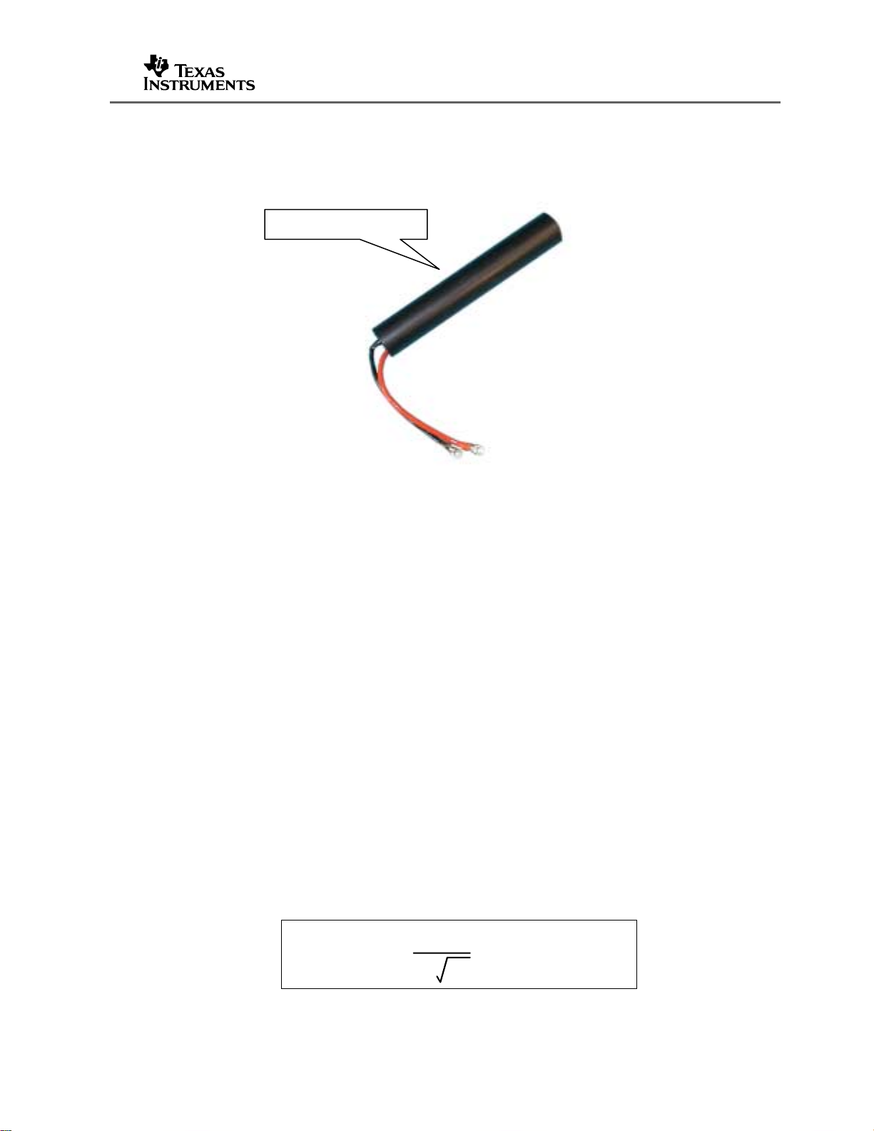
4.6 Ferrite Cored Antennas
Ferrite cored antennas, like Texas Instrument’s stick antennas (RI-ANT-S01C and RIANT-S02C) provide a strong localized RF field and perform well in noisy
environments. They are easy to construct but do need the correct grade of ferrite for
the core – Texas Instruments recommend Philips 3F3 grade. Figure 26 shows the
design of a small, 60 mm (2.4”) long antenna.
Lit Number: 11-06-21-068
Figure 26. Ferrite Cored Antenna
5 Other Antennas
5.1 Field Lines
Texas Instruments LF system uses the magnetic (H) field to transfer energy to the
transponder. When a current moves through an antenna it generates field lines similar
as those shown in Figure 27.
Page (22)
Page 29

Lit Number: 11-06-21-068
Figure 27. Field Lines
The result is that in different parts of the field, the tag couples better and receives the
charge-up energy, while in other parts of the field no energy transfer takes place.
Stick Antenna Gate Antenna
Figure 28. Antenna Field patterns
The result is the field patterns shown in Figure 28.
5.2 Opposing Antennas (In-Phase)
When two individual antennas are connected to the same RF module, they act as one
antenna but can greatly increase the reading range. If they are connected in-phase
the field patterns are the same as from a single antenna but a tag can be detected
across a greater width – double the normal range from a single antenna.
Page (23)
Page 30

Lit Number: 11-06-21-068
Figure 29. Opposing Antennas (In-phase)
If standard antennas are used, they are connected in parallel and appear as a single
13.5 µH antenna. This means they have to be used with the Remote Antenna RFM.
A better approach is to make two antennas that are 54 µH (double inductance). When
these antennas are connected in parallel, they appear as 27 µH inductance and can
be used with standard RF module.
Figure 30. Two 54 µH Antennas Connected in Parallel (In-Phase)
Note:
Do not make your double inductance antennas too large. As both
loops are connected to the same reader, they pick up twice the
electrical noise. Also if more than one tag is in the field at once
i.e. at each antenna, you may not get a response.
5.3 Opposing Antennas (out-of-phase)
When two double inductance antennas are connected to the same RF Module but outof-phase (swap over one pair of connectors, or turn one antenna 180º), the RF field is
changed.
Page (24)
Page 31

Lit Number: 11-06-21-068
Figure 31. Opposing Antennas (out-of-phase)
This arrangement is very useful for access control gates, where the badge is always
worn at right angles to the antenna. Changing the field means it will read across the
width without a hole. This technique is used for livestock applications, where the
electronic ear tag is normally in the same orientation as the badge.
Figure 32. Two 54 µH Antennas connected in Parallel (out-of-phase)
Page (25)
Page 32

5.4 Noise Canceling Antennas
When antennas have to operate in an environment with homogeneous noise (not
coming from any one direction), noise canceling antennas may help to restore some
performance. These antennas have multiple loops that are equal and opposite and
any (homogeneous) signal arriving at all loops is cancelled, whereas the tag signal will
arrive at one loop and be received.
Lit Number: 11-06-21-068
A
+
AREA (A + B) = C
Figure 33. Noise Canceling Antenna
These antennas (and the more simple figure-of-eight antenna) are only used where
noise is a problem, as under normal conditions, their read performance is less.
C
-
B
+
Page (26)
Page 33

Lit Number: 11-06-21-068
Appendix A – MicroReader Antenna Designs
Because of the Micro-reader’s modest power output and the requirements for
antennas to perform next to metal, certain constraints have been imposed by design
on antenna construction.
• The antenna Q factor must be less than 20
• The inductance must be between 46 ~ 48 µH
• The maximum recommended size is 200 mm x 200 mm
The Q factor of an antenna is a measure of its effectiveness, unfortunately, the higher
the Q the more easily the antenna is de-tuned by proximity to metal. The micro-reader
is designed for antennas with a Q factor less than 20. If the Q factor exceeds 20:-
• The output capacitors may receive over-voltage and long term damage could
result.
• The antenna may still be resonating when the response from the tag is
• The antenna may be de-tuned by metal when in situ.
Increasing the resistance has the effect of reducing the Q factor and is why in the
following designs high resistance wire is used, or extra resistance added.
The table below lists the parameters of four antennae that meet the design rules and
whose constructions are described in detail in later sections.
Antenna Size
1 10Ø n/a 17 47 40 Off-the-shelf Inductor
2 40Ø 28 14 47 110 Automotive lock barrel size
3 75Ø 15 18 47 160 General purpose antenna
4 200 x 200 8 20 47 270 Largest size recommended.
received. Without built-in damping, the data may not be received correctly.
(mm)
Turns Q L
(µH)
Range
(mm)
32 mm Tag
Notes
Table 3. MicroReader Antenna Designs
Page (27)
Page 34

Lit Number: 11-06-21-068
Antenna 1
This antenna is built from a standard inductor and the resistance reduced by a series
resistor
47 µH INDUCTOR, 1.2 A
(RS No. 228-450)
1Ω RESISTOR, 1W
(RS No. 214-0734)
Figure 34. MicroReader Antenna 1
Antenna 2
This antenna is constructed on a 40 mm diameter plastic tube former.
27 TURNS
(0.2 mm Enamelled wire)
40 mm
Figure 35. MicroReader Antenna 2
Page (28)
Page 35

Lit Number: 11-06-21-068
Antenna 3
Antenna three is 75 mm in diameter and formed around a slice of plastic water pipe.
15 TURNS
(0.2 mm Enamelled wire)
75 mm
Figure 36. MicroReader Antenna 3
Page (29)
Page 36

Lit Number: 11-06-21-068
Antenna 4
This antenna is constructed around a 6 mm thick MDF former.
Tip:
For such antennas, double sided Scotch tape will retain the thin wire in
position during winding.
8 TURNS
(0.312 mm Enamelled wire)
200 mm
Figure 37. MicroReader Antenna 4
Page (30)
Page 37

Lit Number: 11-06-21-068
Page (31)
Page 38

Lit Number: 11-06-21-068
Appendix B. Contacts
Litze wire
Rudolph Pack +49 2261 53185
Gummersbach
Germany
http://www.pack-feindraehte.de/packE.html
The Deeter Group +44 1494 450020
High Wycombe
UK
http://www.deeter.co.uk/litz.htm
New England Electric Wire Corp +1 603 838 6625
Boston, USA
http://www.newenglandelectricwire.com/litzwire.shtml
Yu Seung Electronics Co Ltd +82 41863 8100
Korea
http://www.yuseung.com/frame.html
Ferrite
Ferroxcube (was Philips)
http://www.ferroxcube.com
Delton-Hawnt (UK distributor for Fair-rite & Ferroxcube) +44 121 7645669
UK
http://www.deltron-hawnt.com/magnetics/portfolio.shtml
Page (32)
 Loading...