

Page 1

The Embedded I/O Compan
y
TXMC885
Four Channel 10/100/1000 Mbit/s Ethernet Adapter
Version 1.0
User Manual
Issue 1.0.0
October 2011
TEWS TECHNOLOGIES GmbH
Am Bahnhof 7 25469 Halstenbek, Germany
Phone: +49 (0) 4101 4058 0 Fax: +49 (0) 4101 4058 19
e-mail: [email protected]
www.tews.com
Page 2

TXMC885 User Manual Issue 1.0.0 Page 2 of 12
TXMC885-10R
Four channel 10/100/1000 Mbit/s Ethernet
interface RJ45 front panel I/O, extended
temperature range
(RoHS compliant)
This document contains information, which is
proprietary to TEWS TECHNOLOGIES GmbH. Any
reproduction without written permission is forbidden.
TEWS TECHNOLOGIES GmbH has made any
effort to ensure that this manual is accurate and
complete. However TEWS TECHNOLOGIES GmbH
reserves the right to change the product described
in this document at any time without notice.
TEWS TECHNOLOGIES GmbH is not liable for any
damage arising out of the application or use of the
device described herein.
Style Conventions
Hexadecimal characters are specified with prefix 0x,
i.e. 0x029E (that means hexadecimal value 029E).
For signals on hardware products, an ‚Active Low’ is
represented by the signal name with # following, i.e.
IP_RESET#.
Access terms are described as:
W Write Only
R Read Only
R/W Read/Write
R/C Read/Clear
R/S Read/Set
©2011 by TEWS TECHNOLOGIES GmbH
All trademarks mentioned are property of their respective owners.
Page 3

TXMC885 User Manual Issue 1.0.0 Page 3 of 12
Issue Description Date
1.0.0 Initial issue October 2011
Page 4

TXMC885 User Manual Issue 1.0.0 Page 4 of 12
Table of Contents
1 PRODUCT DESCRIPTION ...........................................................................................6
2 TECHNICAL SPECIFICATION .....................................................................................7
3 PCI DEVICE TOPOLOGY ON TXMC885......................................................................8
4 GIGABIT ETHERNET CONTROLLER..........................................................................9
4.1 Intel 82574IT PCI Header................................................................................................................9
4.2 Configuration EEPROM................................................................................................................10
5 LEDS...........................................................................................................................11
6 PIN ASSIGNMENT – I/O CONNECTORS...................................................................12
Page 5

TXMC885 User Manual Issue 1.0.0 Page 5 of 12
List of Figures
FIGURE 1-1 : BLOCK DIAGRAM......................................................................................................................6
FIGURE 3-1 : PCI DEVICE TOPOLOGY..........................................................................................................8
FIGURE 5-1 : LEDS AND MARKINGS (BOTTOM VIEW)..............................................................................11
FIGURE 6-1 : FRONT PANEL VIEW..............................................................................................................12
List of Tables
TABLE 2-1 : TECHNICAL SPECIFICATION.....................................................................................................7
TABLE 4-1 : INTEL 82574IT PCI HEADER ......................................................................................................9
TABLE 4-2 : INTEL 82574IT CONFIGURATION EEPROM SETTINGS........................................................10
TABLE 5-1 : LED STATUS..............................................................................................................................11
TABLE 6-1 : FRONT I/O PIN ASSIGNMENT..................................................................................................12
Page 6
TXMC885 User Manual Issue 1.0.0 Page 6 of 12
1 Product Description
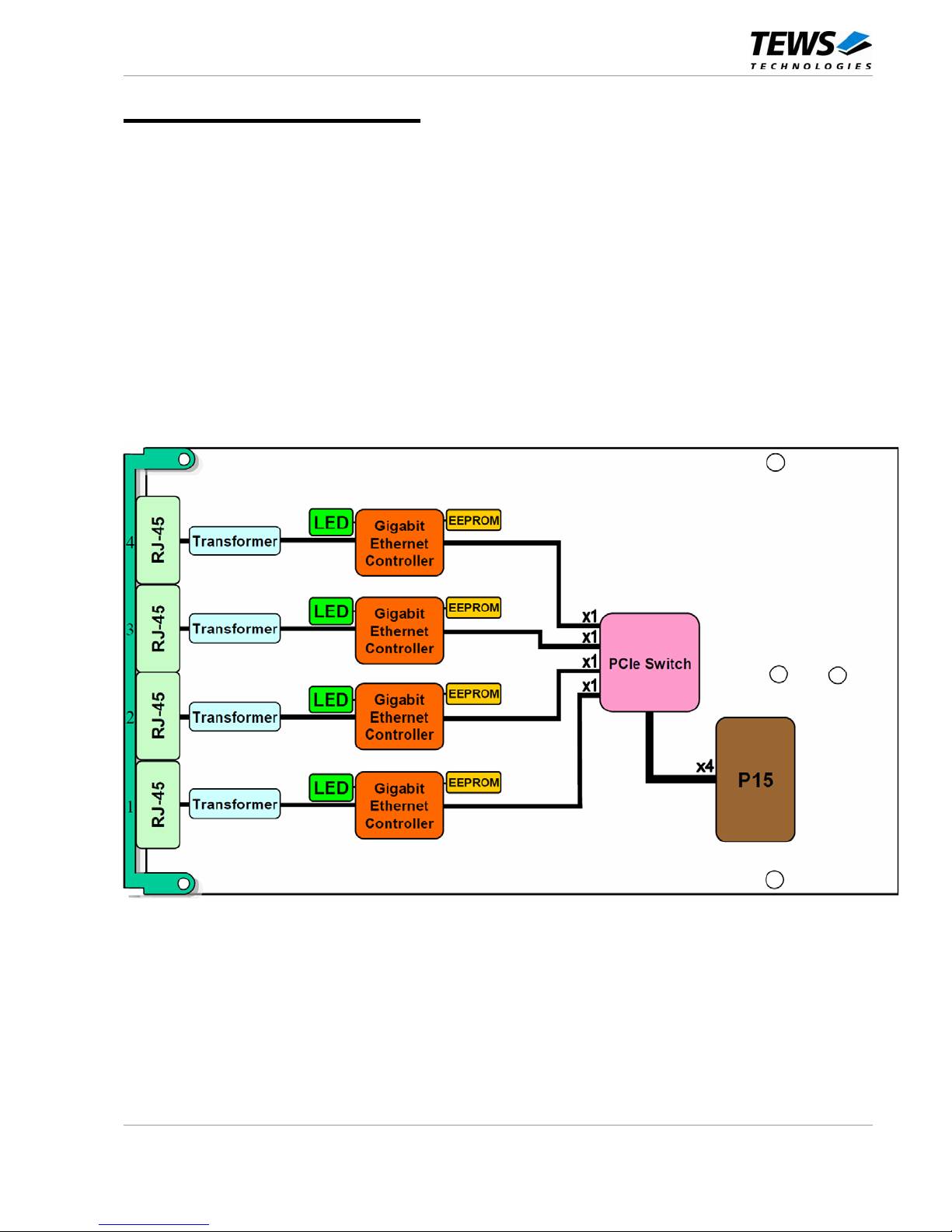
The TXMC885 is a Switched Mezzanine Card (XMC) compatible module providing a four channel Ethernet
10BASE-T / 100BASE-TX / 1000BASE-T interface.
A PCI Express Switch provides access to the Intel 82574IT Gigabit Ethernet controllers. Each Ethernet
interface supports 10, 100 and 1000 Mbit/s transmission rates for full duplex operation, 10 and 100 Mbit/s
transmissions for half duplex operation, and is equipped with a 32 Kbit serial EEPROM.
The four Ethernet interfaces of the TXMC885 are capable of performing an auto negotiation algorithm which
allows both link-partners to find out the best link-parameters by themselves. The TXMC885 is widely user
configurable via configuration and status register access over the PCI Express interface.
The TXMC885-10R provides four 10/100/1000 Mbit/s Ethernet connections via front panel RJ45 connectors.
All ports are galvanically isolated from the Ethernet controllers and LEDs on the board indicate the different
network activities.
The module meets the requirements to operate in extended temperature range from -40° to +85°C.
Figure 1-1 : Block Diagram
Page 7

TXMC885 User Manual Issue 1.0.0 Page 7 of 12
2 Technical Specification
XMC Interface
Mechanical Interface
Switched Mezzanine Card (XMC) Interface confirming to ANSI/VITA
42.0-2008 (Auxiliary Standard)
Standard single-width (149mm x 74mm)
Electrical Interface
PCI Express (Base Specification 1.1) compliant interface conforming
to ANSI/VITA 42.3-2006 (XMC PCI Express Protocol Layer
Standard)
On Board Devices
PCIe Switch
89HPES8T5A (IDT)
Gigabit Ethernet Controller
For each interface: 82574IT (Intel)
IPMI resource FRU Data EEPROM
M24C02 (STMicroelectronics)
Ethernet Interface
Number of Interfaces
4
Link
10Base-T / 100Base-TX / 1000Base-T
FIFO
For each interface: Configurable receive and transmit data FIFO,
programmable in 1 KB increments
Interrupts
PCIe Switch is able to generate
• INTx (x= A, B, C, or D) legacy interrupts
• Message Signaled Interrupts (MSIs)
I/O Connector
RJ45 jacks (Tyco 406732-2 or compatible)
Physical Data
Ambient Air Cooling
Constant airflow of 2 m/s required
Power Requirements
300mA typical @ VPWR = +12V DC (no link)
app. additional 3mA per 100Mbit/s link
app. additional 100mA per 1Gbit/s link
750mA typical @ VPWR = +5V DC (no link)
app. additional 7mA per 100Mbit/s link
app. additional 250mA per 1Gbit/s link
Temperature Range
Operating
Storage
-40°C to +85°C
-40°C to +85°C
MTBF
483000 h
MTBF values shown are based on calculation according to MIL-HDBK-217F and
MIL-HDBK-217F Notice 2; Environment: GB 20°C.
The MTBF calculation is based on component FIT rates provided by the component
suppliers. If FIT rates are not available, MIL-HDBK-217F and MIL-HDBK-217F Notice
2 formulas are used for FIT rate calculation.
Humidity
5 – 95 % non-condensing
Weight
79 g
Table 2-1 : Technical Specification
Page 8
TXMC885 User Manual Issue 1.0.0 Page 8 of 12
3 PCI Device Topology on TXMC885
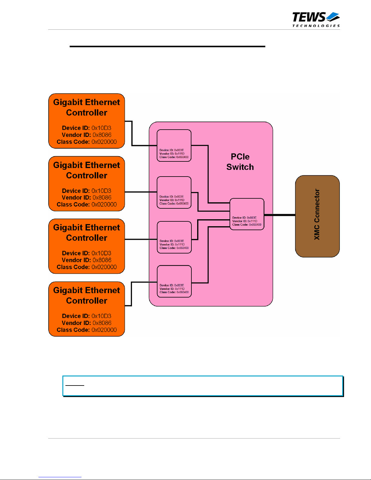
The TXMC885 uses four Gigabit Ethernet Controllers (Intel 82574IT) each communicating via a PCIe
Rev. 1.1 compliant x1 Interface. To be able to access the Ethernet controllers they are connected to the x1
Downstream Ports of a PCIe Switch (IDT 89HPES8T5A). The x4 Upstream Port of the Switch is connected
to the XMC Connector communicating with the host system.
Figure 3-1 : PCI Device Topology
NOTE:
Operating systems typically assign the lowest available Ethernet device number to
PORT4, thus initializing the four ports in descending order.
Page 9

TXMC885 User Manual Issue 1.0.0 Page 9 of 12
4 Gigabit Ethernet Controller
4.1 Intel 82574IT PCI Header
Write ‘0’ to all unused (Reserved) bits PCI CFG
Register
Address
31 24 23 16 15 8 7 0
Initial Values
(Hex Values)
0x00 Device ID Vendor ID 10D3 8086
0x04 Status Register Command Register 0010 0000
0x08 Class Code Revision ID 020000 00
0x0C BIST Header Type Latency Timer
Cache Line
Size
00 00 00 10
0x10 Base Address 0
(Memory BAR)
FFFE0000
(128 KByte)
0x14 Base Address 1
(Flash BAR)
00000000
0x18 Base Address 2
(IO BAR)
FFFFFFE1
(32 Byte)
0x1C Base Address 3
(MSI-X BAR)
FFFFC000
(16 KByte)
0x20 Base Address 4 00000000
0x24 Base Address 5 00000000
0x28 CardBus CIS Pointer 00000000
0x2C Subsystem ID Subsystem Vendor ID 0000 8086
0x30 Expansion ROM Base Address 00000000
0x34 Reserved Cap_Ptr 000000 C8
0x38 Reserved 00000000
0x3C Max_Latency Min_Grant Interrupt Pin Interrupt Line 00 00 01 00
Table 4-1 : Intel 82574IT PCI Header
Page 10
TXMC885 User Manual Issue 1.0.0 Page 10 of 12
4.2 Configuration EEPROM
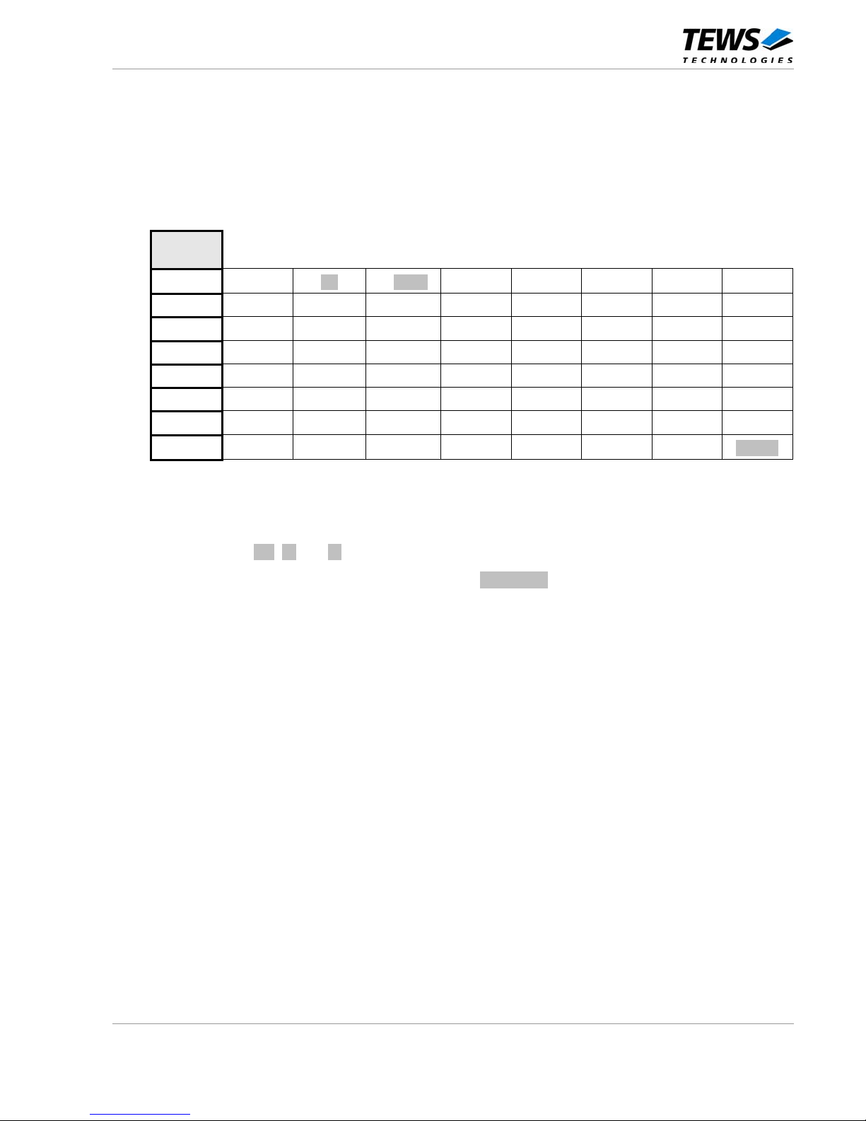
After power-on or PCI reset, each Intel 82574IT Ethernet Controller loads its initial configuration register data
from the corresponding on board configuration EEPROM.
See the Intel 82574 GbE Controller Family Datasheet for more information.
Word
Address
0x00
0x0100
0xww06 0xzzyy
0x0624 0xF444 0x0000 0x0000 0x0000
0x08
0x0000 0x0000 0x0E6B 0x0000 0x8086 0x10D3 0x0000 0x0558
0x10
0x0000 0xFF01 0x7E04 0x0000 0x0000 0x00A8 0x0000 0x0704
0x18
0x6CC9 0x3150 0x070E 0x4503 0x2DA4 0x0000 0x4300 0xA4A4
0x20
0xFF00 0x8080 0x0F04 0x7FFF 0x6801 0x0000 0x0000 0x0000
0x28
0x0000 0x0000 0x0000 0x0000 0x0000 0x0000 0x0000 0x0000
0x30
0x0000 0x0000 0x0000 0x0000 0x0000 0x0000 0x0000 0x0000
0x38
0x0000 0x0000 0x0000 0x0000 0x0000 0x0000 0x0000
check
Table 4-2 : Intel 82574IT Configuration EEPROM Settings
The EEPROM Word Addresses 0x00 to 0x02 contain the factory programmed individual Ethernet (MAC)
Address. The value of ww, zz and yy is unique for each Intel 82574IT Ethernet controller.
The EEPROM Word Address 0x3F contains the EEPROM checksum.
Page 11
TXMC885 User Manual Issue 1.0.0 Page 11 of 12
5 LEDs
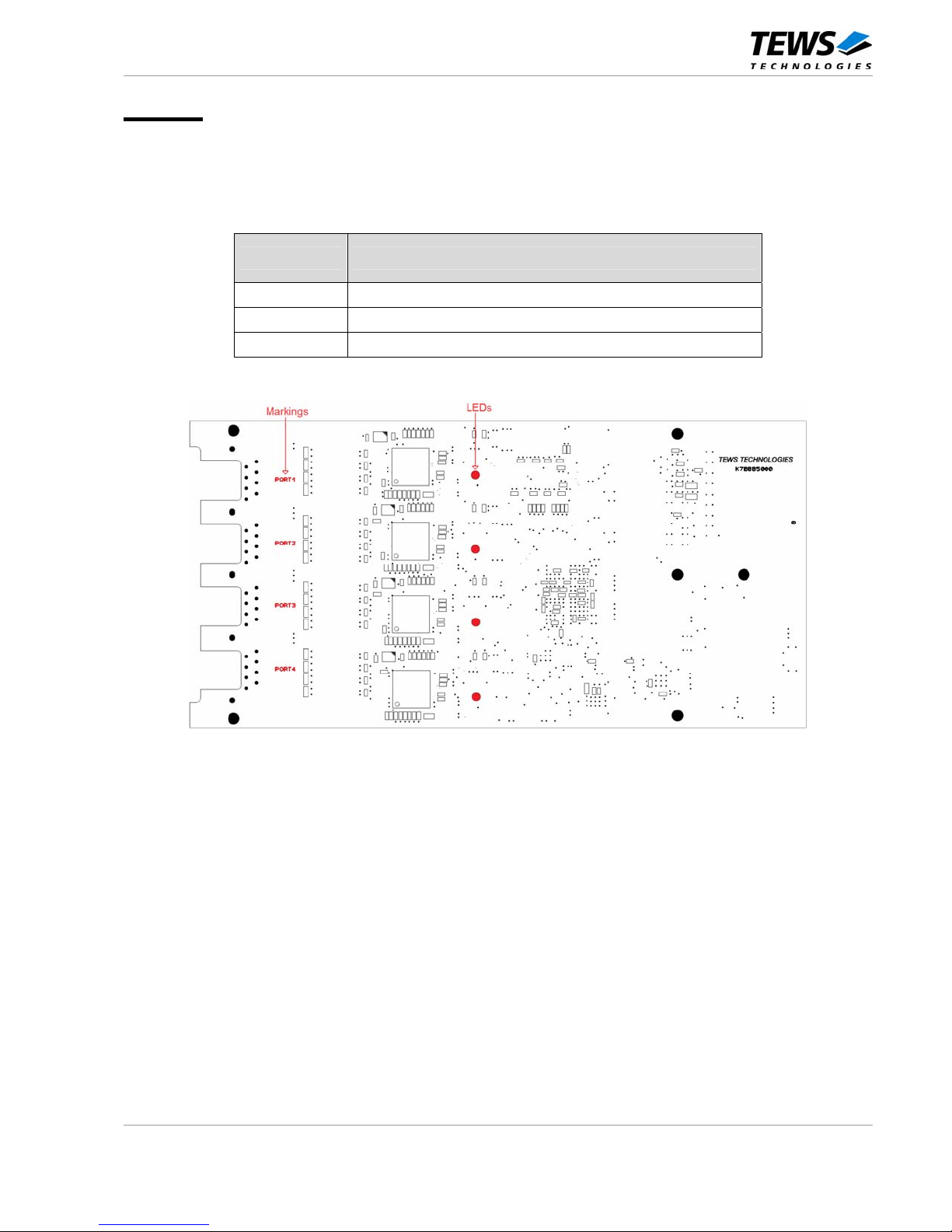
The TXMC885 provides four Status LEDs for quick visual inspection and debugging. Due to the fact that
XMCs are mounted headfirst on the carrier card, the LED indicators are visible on the back side of the
TXMC885. A marking is placed close to each LED, to indicate the Ethernet Port the LED corresponds to.
Each Ethernet Port has one LED indicator. See figures below for more details:
LED Status Description
OFF
No cable is connected or no link is established
ON
A link is established at the corresponding Ethernet Port
BLINKING
Indicates activity: The Ethernet Port transmits or receives data
Table 5-1 : LED Status
Figure 5-1 : LEDs and markings (bottom view)
Page 12
TXMC885 User Manual Issue 1.0.0 Page 12 of 12
6 Pin Assignment – I/O Connectors
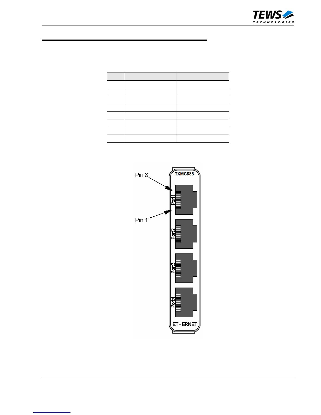
On the TXMC885, the Ethernet signals are accessible by four RJ45 jacks. The connectors are located in the
XMC front panel.
For pin assignment and front panel labeling, see the figures below.
Pin Signal (1000) Signal (100, 10)
1 TX0/RX0+ TX+
2 TX0/RX0- TX3 TX1/RX1+ RX+
4 TX2/RX2+ not used
5 TX2/RX2- not used
6 TX1/RX1- RX7 TX3/RX3+ not used
8 TX3/RX3- not used
Table 6-1 : Front I/O pin assignment
Figure 6-1 : Front panel view
 Loading...