

Page 1

The Embedded I/O Company
TPMC883
10/100/1000 Mbit/s Ethernet Adapter
Version 1.0
RoHS comliant Version:
Version 2.0
User Manual
Issue 1.2
March 2008
D76883800
TEWS TECHNOLOGIES GmbH TEWS TECHNOLOGIES LLC
Am Bahnhof 7
25469 Halstenbek, Germany
www.tews.com
Phone: +49-(0)4101-4058-0
Fax: +49-(0)4101-4058-19
e-mail: [email protected]
9190 Double Diamond Parkway,
Suite 127, Reno, NV 89521, USA
www.tews.com
Phone: +1 (775) 850 5830
Fax: +1 (775) 201 0347
e-mail: [email protected]
Page 2

TPMC883 User Manual Issue 1.2 Page 2 of 10
TPMC883-10
10/100/1000 Mbit/s Ethernet Adapter
Front panel connector
based on Intel 82545EM Ethernet Controller
TPMC883-10R
10/100/1000 Mbit/s Ethernet Adapter
Front panel connector
based on Intel 82545GM Ethernet Controller
This document contains information, which is
proprietary to TEWS TECHNOLOGIES GmbH. Any
reproduction without written permission is forbidden.
TEWS TECHNOLOGIES GmbH has made any
effort to ensure that this manual is accurate and
complete. However TEWS TECHNOLOGIES GmbH
reserves the right to change the product described
in this document at any time without notice.
TEWS TECHNOLOGIES GmbH is not liable for any
damage arising out of the application or use of the
device described herein.
Style Conventions
Hexadecimal characters are specified with prefix 0x,
i.e. 0x029E (that means hexadecimal value 029E).
For signals on hardware products, an ‚Active Low’ is
represented by the signal name with # following, i.e.
IP_RESET#.
Access terms are described as:
W Write Only
R Read Only
R/W Read/Write
R/C Read/Clear
R/S Read/Set
©2005-2008 by TEWS TECHNOLOGIES GmbH
Page 3

TPMC883 User Manual Issue 1.2 Page 3 of 10
Issue Description Date
1.0 First Issue June 2005
1.1 New address TEWS LLC September 2006
1.2 RoHS compliant version TPMC883-10R added March 2008
Page 4

TPMC883 User Manual Issue 1.2 Page 4 of 10
Table of Contents
1 PRODUCT DESCRIPTION.........................................................................................6
2 TECHNICAL SPECIFICATION...................................................................................7
3 82545 GIGABIT ETHERNET CONTROLLER............................................................8
3.1 82545 PCI Header............................................................................................................................8
3.2 Configuration EEPROM..................................................................................................................9
4 PIN ASSIGNMENT – I/O CONNECTOR ..................................................................10
4.1 Front Panel I/O Connector ...........................................................................................................10
4.2 Front Panel LED Indicators..........................................................................................................10
Page 5

TPMC883 User Manual Issue 1.2 Page 5 of 10
Table of Figures
FIGURE 1-1 : BLOCK DIAGRAM......................................................................................................................6
FIGURE 2-1 : TECHNICAL SPECIFICATION...................................................................................................7
FIGURE 3-1 : 82545 PCI HEADER...................................................................................................................8
FIGURE 3-2 : 82545 CONFIGURATION EEPROM SETTINGS.......................................................................9
FIGURE 4-1 : FRONT I/O PIN ASSIGNMENT................................................................................................10
FIGURE 4-2 : LED STATUS DEFINITIONS....................................................................................................10
Page 6
TPMC883 User Manual Issue 1.2 Page 6 of 10
1 Product Description
The TPMC883 is a PCI Mezzanine Card (PMC) compatible module providing a single channel Gigabit
Ethernet 10 / 100 / 1000BASE-TX interface.
For highest data rates, the TPMC883 has a 64 bit, 133/100/66 MHz PCI bus interface and is capable
of full speed bus-master DMA operations utilizing maximum PCI bandwidth.
An Intel™ 82545EM Ethernet Controller (82545GM for RoHS compliant product) is used, which
supports 10, 100 and 1000 Mbit/s transmission rates for half and full duplex operation. The TPMC883
is capable of performing an auto negotiation algorithm which allows both link-partners to find out the
best link-parameters by themselves. The TPMC883 is widely user configurable via configuration and
status register access over the PCI bus. Front panel mounted LEDs indicate various network activities.
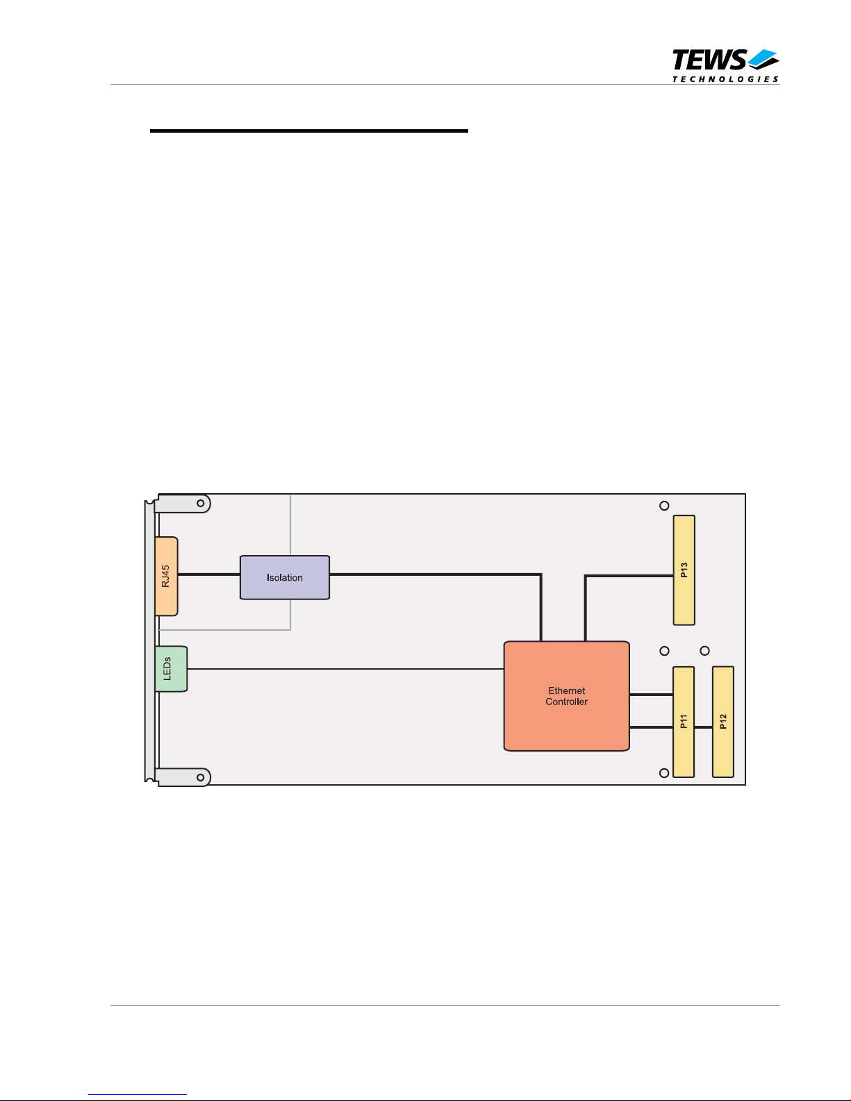
The TPMC883-10 provides a 10/100/1000 Mbit/s network connection via a front panel RJ45
connector. The port is galvanically isolated from the Ethernet Controller.
The operating temperature range is 0°C to +70°C.
Figure 1-1 : Block Diagram
Page 7

TPMC883 User Manual Issue 1.2 Page 7 of 10
2 Technical Specification
PMC Interface
Mechanical Interface
PCI Mezzanine Card (PMC) Interface
Single Size
Electrical Interface
PCI 2.2 (64 bit / 66 MHZ) and PCI-X 1.0a (64 bit / 133 MHz)
compliant interface
3.3V and 5V PCI Signaling Voltage
On Board Devices
Ethernet Controller with
Integrated PCI and Physical
Interface
Intel 82545EM
Intel 82545GM (RoHS compliant version)
Ethernet Interface
Number of Channels
1
FIFO
64 Kbyte Transmit and Receive FIFOs
Interrupts
Using PCI INTA
I/O Connector
Front panel Modular Jack
Physical Data
Power Requirements
1000 mA typical @ +3.3V DC
Temperature Range
Operating
Storage
0 °C to 70 °C
-40°C to +70°C
MTBF
418000 h
Humidity
5 – 95 % non-condensing
Weight
65 g
Figure 2-1 : Technical Specification
Page 8

TPMC883 User Manual Issue 1.2 Page 8 of 10
3 82545 Gigabit Ethernet Controller
3.1 82545 PCI Header
PCI Configuration Register
Offset
31 - 24 23 - 16 15 - 08 07 - 00
Setting
0x00 Device ID Vendor ID 0xYYYY_8086
0x04 Status Command 0x0230_0007
0x08 Class Code Revision ID 0x0200_00xx
0x0C BIST Header Latency Cache Line 0x0000_xx00
0x10
PCI Base Address 0
(Memory Mapped Configuration Register)
0xFFFE_0000
(128 Kbyte)
0x14
PCI Base Address 2
(Memory Mapped FLASH Space)
0xFFFF_0000
(64 Kbyte)
0x18
PCI Base Address 1
(I/O Mapped Configuration Register)
0xFFFF_FFF9
(8 Byte)
0x1C Reserved 0x0000_0000
0x20 Reserved 0x0000_0000
0x24 Reserved 0x0000_0000
0x28 Reserved 0x0000_0000
0x2C Subsystem ID Subsystem Vendor ID 0x0373_1498
0x30 Expansion ROM PCI Base Address 0x0000_0000
0x34 Reserved Cap. Pointer 0x0000_00DC
0x38 Reserved 0x0000_0000
0x3C Max_Lat Min_Gnt Interrupt Pin Interrupt Line 0x00FF_0100
0xDC Power Management Cap. Next Cap. Cap. ID 0x7E22_0001
0xE0 Reserved Data Power Management CSR 0x4B00_4000
Figure 3-1 : 82545 PCI Header
Device-ID:
YYYY (Device-ID) is different for TPMC883-10 and TPMC883-10R:
100F for TPMC883-10
1026 for TPMC883-10R
Page 9

TPMC883 User Manual Issue 1.2 Page 9 of 10
3.2 Configuration EEPROM
After power-on or PCI reset the 82545 loads the initial configuration register data from the on board
configuration EEPROM.
See the 82545 Manual for more information.
EEPROM
Address
Offset
0x00 0x02 0x04 0x06 0x08 0x0A 0x0C 0x0E
0x00 0xYYYY 0xYYYY 0xYYYY 0x0420 0xFFFF 0xFFFF 0xFFFF 0xFFFF
0x10 0x0000 0x0000 0x4406 0x0373 0x1498 0x0373 0x1498 0x30E8
0x20 0x0000 0x0373 0x0000 0x0000 0x38C8 0xFFFF 0xFFFF 0xFFFF
0x30 0xFFFF 0xFFFF 0xFFFF 0xFFFF 0xFFFF 0xFFFF 0xFFFF 0xFFFF
0x40 0x0000 0x7863 0x0000 0x0000 0x28C8 0xFFFF 0xFFFF 0xFFFF
0x50 0xFFFF 0xFFFF 0xFFFF 0xFFFF 0xFFFF 0xFFFF 0xFFFF 0x0602
0x60 0x90EC 0x0000 0x0000 0x0001 0x90EC 0x0000 0x0000 0x0000
0x70 0x0000 0x0000 0x0000 0x0000 0x0000 0x0000 0x0000 0xZZZZ
Figure 3-2 : 82545 Configuration EEPROM Settings
YYYY = Individual Ethernet Address
ZZZZ = EEPROM Checksum
Page 10

TPMC883 User Manual Issue 1.2 Page 10 of 10
4 Pin Assignment – I/O Connector
4.1 Front Panel I/O Connector
Pin Signal
1 TX0/RX0+
2 TX0/RX03 TX1/RX1+
4 TX2/RX2+
5 TX2/RX26 TX1/RX17 TX3/RX3+
8 TX3/RX3-
Figure 4-1 : Front I/O Pin Assignment
4.2 Front Panel LED Indicators
The Ethernet Channel provides 4 LED indicators: 100, 1000, LINK and ACT. See table below for
detail:
Name Description
100 Indicates 100BaseT Speed when LED is on
1000 Indicates 1000BaseT Speed when LED is on
LINK Indicates Link established when Led is on
ACT Indicates Activity when LED is on
Figure 4-2 : LED Status Definitions
When both Speed LEDs are off, then a 10BaseT Speed connection is established.
 Loading...