

Page 1

.
Thermoelectric Cooling Assembly (TCA)
Instruction Manual
Drawing 4921-1 Rev. D, 07 July 2010
TE
1590 Keane Drive Phone: (231) 929-3966
Traverse City, MI 49696 USA Fax: (231) 929-4163
http://www.tetech.com e-mail: [email protected]
All Materials Copyright © 2007 - 2009 TE Technology, Inc.
TECHNOLOGY, INC
Page 2

.
TE Technology, Inc. does not make any warranty, expressed or implied, that the
use or operation of the equipment will be functional or effective if the equipment
is not installed and used in accordance with this manual.
TE Technology, Inc. shall not be liable, and Purchaser shall defend, hold
harmless, and indemnify TE Technology, Inc. from and against, any losses,
costs, expenses (including reasonable attorneys’ fees), injuries, liabilities or
damages of any kind or nature whatsoever, arising out of or from the omission or
failure to use protective devices or comply with this manual. This provision is in
addition to any other indemnification provisions which are a part of the Purchase
Order or contract with Purchaser.
TE
http://www.tetech.com email: [email protected]
TECHNOLOGY, INC
2/22
Page 3

.
This Thermoelectric Cooling Assembly (TCA) Instruction Manual must
be read and followed carefully before installation and operation.
! Follow all recommendations and suggestions, heed all warnings contained in
this manual and use the product as intended. Failure to do so could result in
hazards and loss or damage to the TCA and/or secondary equipment.
! Only qualified technicians should install and configure the TCA.
! Use of the TCA is restricted to operators capable of understanding one of the
languages presented in this manual, as stated by agreement between TE
Technology, Inc. and the Purchaser.
! The TCA is intended to be operated in a light industrial environment only.
! Do not use in an explosive or potentially explosive environment.
! Do not use the TCA if damaged.
! Do not disassemble TCA. No user serviceable parts inside.
! Do not operate the TCA outside the specified operating temperature range.
Condensation could form on cooled sections of the TCA and on secondary
equipment. This condensate and any subsequent drainage onto other secondary
equipment could pose hazards and/or damage to the TCA and/or secondary
equipment. If such hazards are present, devices should be added to prevent or
remove the condensate such as dehumidifiers, dry gas purge systems,
desiccants, etcetera. Alternatively, cooled sections of the TCA and secondary
equipment should be restricted from being cooled below the dew-point
temperature.
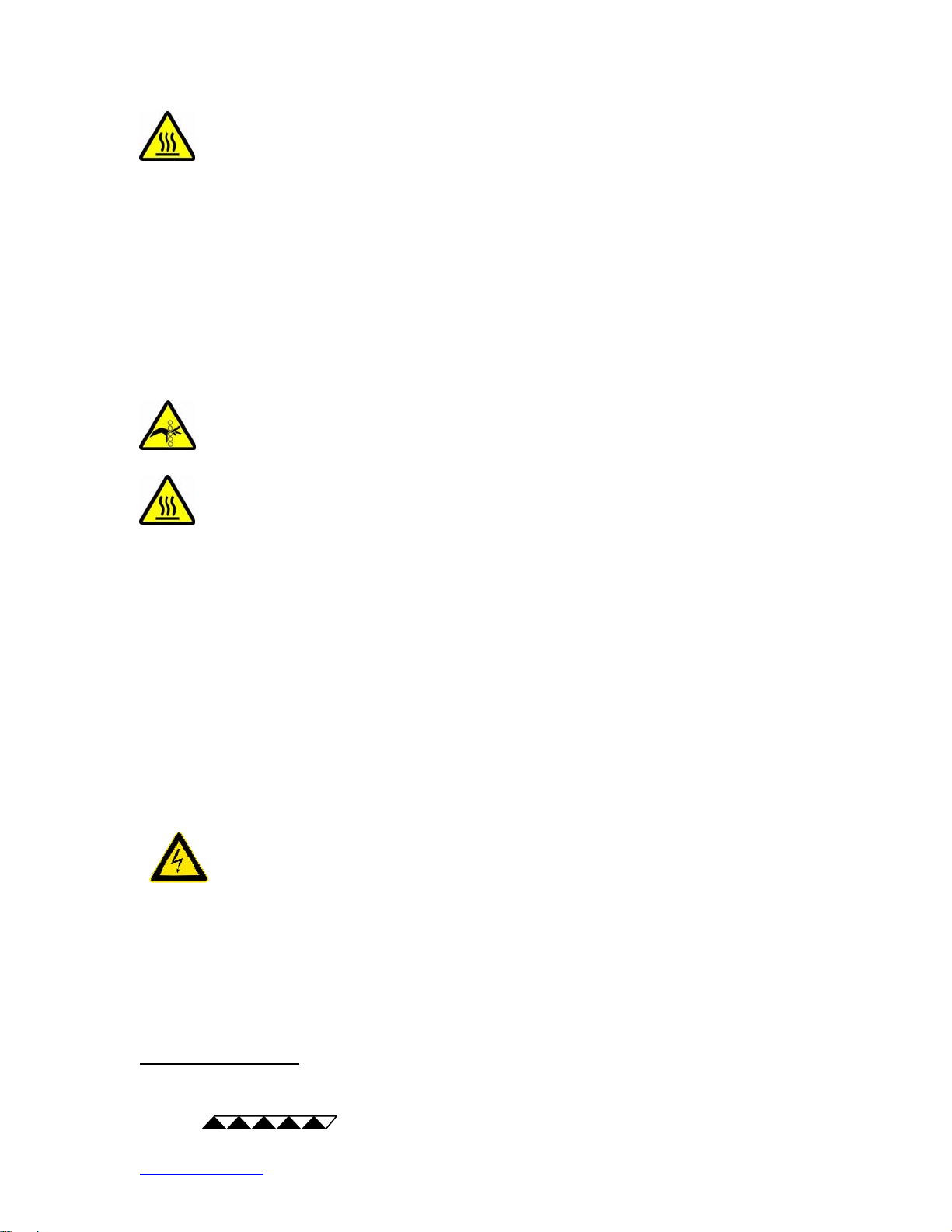
Portions of the TCA could exceed 60 °C during normal operating
conditions resulting in a hazard. Use caution! Protect against contact with hot
surfaces.
TE
http://www.tetech.com email: [email protected]
TECHNOLOGY, INC
3/22
Page 4

.
! When using a temperature controller, improper configuration of the
temperature controller, improper installation of a temperature sensor, or the use
of an incorrect temperature sensor can result in hazards or damage to the TCA
or secondary equipment.
! Hazards, excessive hot or cold temperatures, and damage to the TCA or
secondary equipment can occur from fault conditions or human errors such as:
1. Incorrect wiring of the TCA.
2. Failure or misuse of the TCA.
3. Failure or misuse of the control device used with the TCA.
4. Reduction in the flow of cooling air or liquid.
Special Liquid Heat Exchanger Warnings:
If the TCA has one or more liquid heat exchangers, mount the TCA in a
position so that an unexpected liquid leak will be diverted away from electrical
circuitry and sensitive equipment into a containment area where damage to the
equipment and/or hazards will not result.
Do not allow the liquid in the liquid heat exchanger to freeze or overheat, whether
in operation or in storage. Before use, purge all air from the liquid heat
exchanger for proper operation and to prevent overheating.
! The liquid heat exchangers are designed for use with filtered, distilled water.
Other fluids may be acceptable for use if and only if TE Technology has provided
express written notice that they are compatible with the liquid exchanger. Do not
use fluids which have not been approved by TE Technology. Otherwise, damage
and/or hazards could result.
! Do not exceed the specified operating maximum liquid pressure as noted on
the TCA specification sheet or 205 kPa if it is not otherwise specified.
Additional Operation Warnings:
! Proper operation of the TCA is dependant on sufficient air flow through the
fans, heat sink fins, and/or the liquid heat exchanger if so equipped.
! Do not obstruct air flow or liquid flow to the TCA or use in areas where the
heat sink is not well ventilated. The fan and cooling fins should be kept clear of
dirt and dust. Clean by directing compressed air over the fins.
TE
http://www.tetech.com email: [email protected]
TECHNOLOGY, INC
4/22
Page 5
.
Do not operate the TCA if the heat-sink fan is not operational. This could
cause damage and create hazards from the heat sink being greater than 60 °C.
Do not operate the TCA if the heat-sink fan is operational but exhibits bearing
noise or is otherwise not operating as normally expected.
! Frost/ice should not be allowed to form on the heat sink, fan(s), or cold sink (if
so equipped) as this could obstruct air flow and decrease performance and/or
cause damage to the TCA and secondary equipment. If frost/ice contacts the
cold-sink or heat-sink fan, de-energize the TCA until the frost/ice has been
removed.
Do not operate TCA without finger guards. This could result in a hazard.
Portions of the TCA (the heat sink, for example) will become warmer
than the ambient temperature. They can become hotter than 60 °C even if
control temperatures of greater than 60 °C are not desired. The operating
temperature of the TCA depends on many factors: ambient temperature, input
power, and heat pumping. If the TCA is to be used in conditions where a portion
of the TCA could possibly exceed 60 °C (for example, if the TCA is operated in
ambient temperatures greater than 35 °C) test the surface temperatures of the
TCA under the worst-case operating conditions of maximum ambient
temperature, highest heat pumping, and maximum input power. If any portion of
the TCA exceeds 60 °C place adequate guards around the TCA to prevent
contact with hot surfaces.
See “Electrical Connections” section for proper connection from controller/power
supply.
Do not:
1. Install the TCA,
2. Attach anything to the TCA, or
3. Operate the TCA or attached equipment,
that would create a voltage potential of 50 V or more on the TCA.
Protective Devices:
TE
http://www.tetech.com email: [email protected]
TECHNOLOGY, INC
5/22
Page 6

.
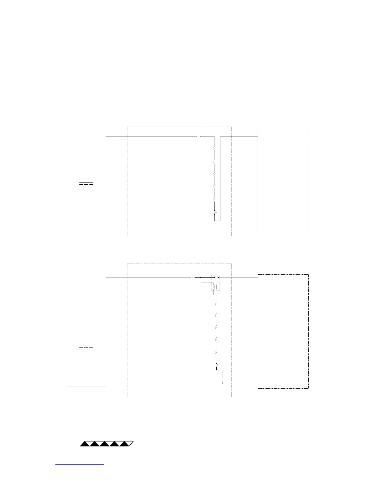
! Use protective devices to prevent hazardous conditions and/or damage to the
TCA and secondary equipment (refer to connection diagram). Protective devices
should be placed at all points on the TCA and secondary equipment where a
hazardous condition can be detected. NOTE: Unless noted in the product
specifications, protective devices are not included.
Protective devices should de-energize the TCA and, as necessary, related
secondary equipment. It is recommended that such devices require the user to
remove and correct the root cause of a fault before allowing the TCA and related
equipment to be re-energized.
! Protective devices must operate independently of the primary temperature
control circuitry.
! Some temperature controllers can detect under-temperature and over-
temperature conditions and can be configured to deenergize the TCA when such
a condition is detected. If a temperature controller is used to provide undertemperature and/or over-temperature detection, it is recommended to monitor the
heat sink and, as necessary, the cold side (cold sink, cold plate, liquid heat
exchanger) for under-temperature and over-temperature conditions. However,
hazards and/or risk of loss or damage to the TCA and/or secondary equipment
could still occur if the temperature controller and/or sensors were to malfunction.
Therefore, independent, redundant protective devices are recommended in
addition to the safeguards provided by the temperature controller. For the
purposes of this manual temperature controllers are not considered protective
devices.
! TE Technology, Inc. shall not be liable, and Purchaser shall defend, hold
harmless, and indemnify TE Technology, Inc. from and against, any losses,
costs, expenses (including reasonable attorneys’ fees), injuries, liabilities or
damages of any kind or nature whatsoever, arising out of or from the omission or
failure to use protective devices.
! Protective devices should include, but are not limited to:
• Fuses to prevent against electrical overloads,
• Over/under temperature thermostats to prevent against hazardous and/or
damaging temperatures,
• Liquid flow meters to prevent against damage due to loss of coolant flow
See “Protective Device Options” below for suggested options.
TE
http://www.tetech.com email: [email protected]
TECHNOLOGY, INC
6/22
Page 7
.
Protective Device Options
(+) (+)
HOT-SIDE, OVER-TEMPERATURE THERMOSTAT
FUSE
DC
POWER
SUPPLY
DC
POWER
SUPPLY
HOT-SIDE, UNDER-TEMPERATURE T HERMOSTAT
COLD-SIDE, OVER-TEMPERATURE THERMOSTAT
COLD-SIDE, UNDER-TEMPERATURE THERMOSTAT
OTHER PROTECTIVE DEVICE (AS REQUIRED)
LIQUID FLOW SENSOR (AS REQUIRED)
(-) (-)
or
FUSE
RELAY
HOT-SIDE, OVER-TEMPERATURE THERMOSTAT
HOT-SIDE, UNDER-TEMPERATURE THERMOSTAT
COLD-SIDE, OVER-TEMPERATURE THERMOSTAT
COLD-SIDE, UNDER-TEMPERATURE THERMOSTAT
OTHER PROTECTIVE DEVICE (AS REQUIRED)
(+)(+)
TCA
(AND OPTIONAL
TEMPERATURE
CONTROLLER)
TCA
(AND OPTIONAL
TEMPERATURE
CONTROLLER)
LIQUID FLOW SENSOR (AS REQUIRED)
TE
http://www.tetech.com email: [email protected]
TECHNOLOGY, INC
7/22
(-)(-)
Page 8
.
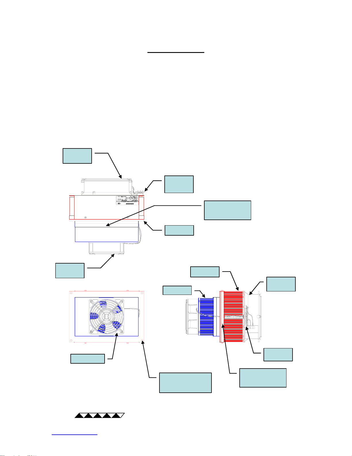
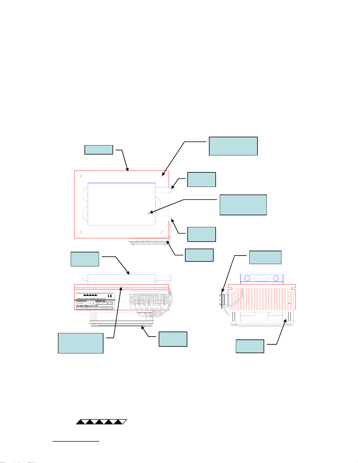
Terminology
TCA – Thermoelectric Cooling Assembly
AC – Air Cooler
CP – Cold Plate
LC – Liquid Cooler
Note: drawings are for illustrative purposes only; consult TCA Specifications for complete details.
AC-xxx TCA Terminology
finger
guard
terminal
block
cover
finger
guard
cold sink fan
TETECHNOLOGY , INC.
gasket
heat sink
cold sink
supplied hole
for mounting
temperature sensor
heat sink
fan
terminal
block
TE
http://www.tetech.com email: [email protected]
TECHNOLOGY, INC
8/22
TCA mounting hole
(threaded or through
hole), typical
supplied hole
for mounting
temperature sensor
Page 9
.
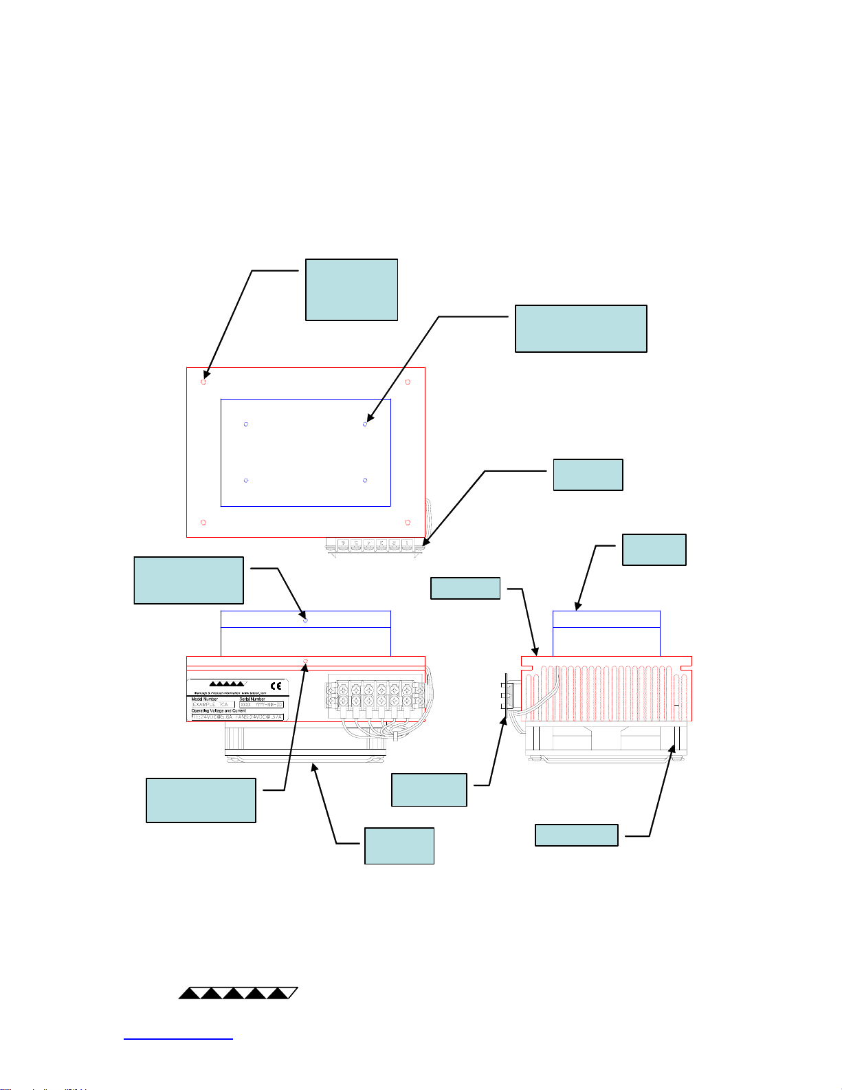
CP-xxx TCA Terminology
TCA mounting
hole (threaded
or through
hole), typical
threaded hole for
mounting part to plate
(location and type vary)
terminal
block
supplied hole
for mounting
temperature sensor
TETECHNOLOGY, INC.
supplied hole
for mounting
temperature sensor
terminal
block cover
finger
guard
cold
plate
heat sink
heat sink fan
TE
http://www.tetech.com email: [email protected]
TECHNOLOGY, INC
9/22
Page 10
.
LC-xxx TCA Terminology
TCA mounting hole
heat sink
inlet/outlet
(threaded or through
hole), typical
tube
supplied hole
for mounting
temperature sensor
liquid heat
exchanger
TETECHNOLOGY, INC.
supplied hole
for mounting
temperature sensor
finger
guard
inlet/outlet
tube
terminal
block
terminal
block cover
heat sink
fan
TE
http://www.tetech.com email: [email protected]
TECHNOLOGY, INC
10/22
Page 11

.
Installation
Mechanical Mounting:
! Improper mounting or installation of the TCA could result in the unit falling,
creating a hazard. Be certain that the structure supporting the TCA is of
sufficient strength for its weight and that all fasteners are properly installed.
! The cold side of the TCA may form condensation. Mount the TCA in a location
that is not affected by condensation, or use caution so that condensate does not
contact areas where damage to the TCA or secondary equipment may result.
Condensate should not be allowed to contact the TCA fan or wires or electrical
connections.
! For AC-xxx units, there is a gasket on the face of the heat sink for the purpose
of sealing against the enclosure wall. The gasket must be compressed to a level
that will ensure proper sealing. Proper compression is dependant upon the
enclosure wall stiffness, the number and location of the mounting holes, the size
of the cooler, etcetera. Generally, the gasket can be completely compressed. A
suitable sealant (one that is weather resistant and provides good adhesion
between the sealing surfaces, possibly, but not necessarily, RTV silicone rubber
sealant, for example) should be applied to ensure proper sealing.
! To maintain a NEMA or IP rating or otherwise to prevent leaks of dust or
liquids, use sealing washers on all screws and seal all openings, gasket
surfaces, and mounting hardware with a suitable sealant.
Note: if the AC-xxx unit has been removed for service, the gasket should be
inspected for its ability to maintain the seal integrity prior to re-installation. If the
gasket is damaged or has lost resiliency, the gasket should be replaced.
! If an AC-xxx or other TCA has a NEMA or IP rating, the sole purpose of the
rating is to state that when installed on an enclosure the TCA can maintain the
seal integrity of the enclosure up to the stated NEMA or IP rating. However, the
TCA must be installed and tested by a qualified technician to verify the seal
integrity as there are a number of design variables which are outside the control
of TE Technology.
TE
http://www.tetech.com email: [email protected]
TECHNOLOGY, INC
11/22
Page 12
.
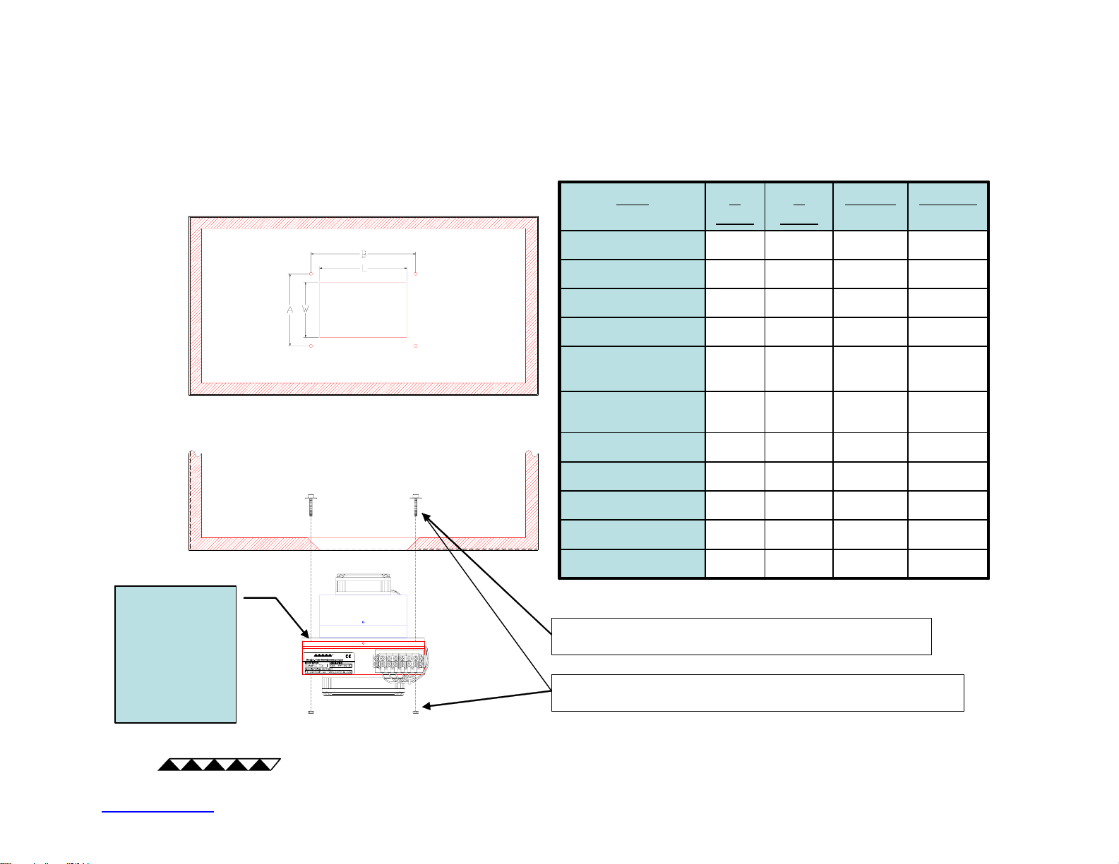
TCA Mounting Hole Dimensions
NOTE: Only AC-xxx
units have gasket for
sealing the opening.
Use sealing washers
and appropriate
sealant on gasket
surface and
mounting hardware
to achieve rated
sealing.
TETECHNOLOGY, INC .
TCA
TCA
AC-027, CP-036
AC-027, CP-036
AC-046, CP-065
AC-046, CP-065
CP-061, AC-053
CP-061, AC-053
CP-121
CP-121
AC-073,
AC-073,
CP-110, CP-127
CP-110, CP-127
CP-200, CP-200HT,
CP-200, CP-200HT,
CP-200TT, CP-200HTTT
CP-200TT, CP-200HTTT
AC-162,CP-218
AC-162,CP-218
AC-140, AC-194
AC-140, AC-194
LC-035
LC-035
LC-061
LC-061
LC-200
LC-200
* This length dimension is required to prevent interference with tubing. The heat
sink face will not completely seal against the outside surface of the opening.
SCREW AND WASHER ONLY FOR: AC-027, AC-046, AC-053, CP-036,
CP-061, CP-065, CP-121, LC-035, LC-061
BOLT, NUT, AND WASHER FOR: AC-073, AC-162, AC-140, AC-194, CP-110,
CP-127, CP-200, CP-218, LC-200
A
A
(mm)
(mm)
(mm)
(mm)
W (mm)L (mm)B
W (mm)L (mm)B
85107127104.6
85107127104.6
85132152.4104.6
85132152.4104.6
82132139.788.9
82132139.788.9
157157127172.2
157157127172.2
97157190.5114.3
97157190.5114.3
157221241.3161
157221241.3161
145221241.3161
145221241.3161
145230246.4161
145230246.4161
85167*127104.6
85167*127104.6
85192*152.4104.6
85192*152.4104.6
157281*241.3161
157281*241.3161
TE
http://www.tetech.com email: [email protected]
TECHNOLOGY, INC
12/22
Page 13
.
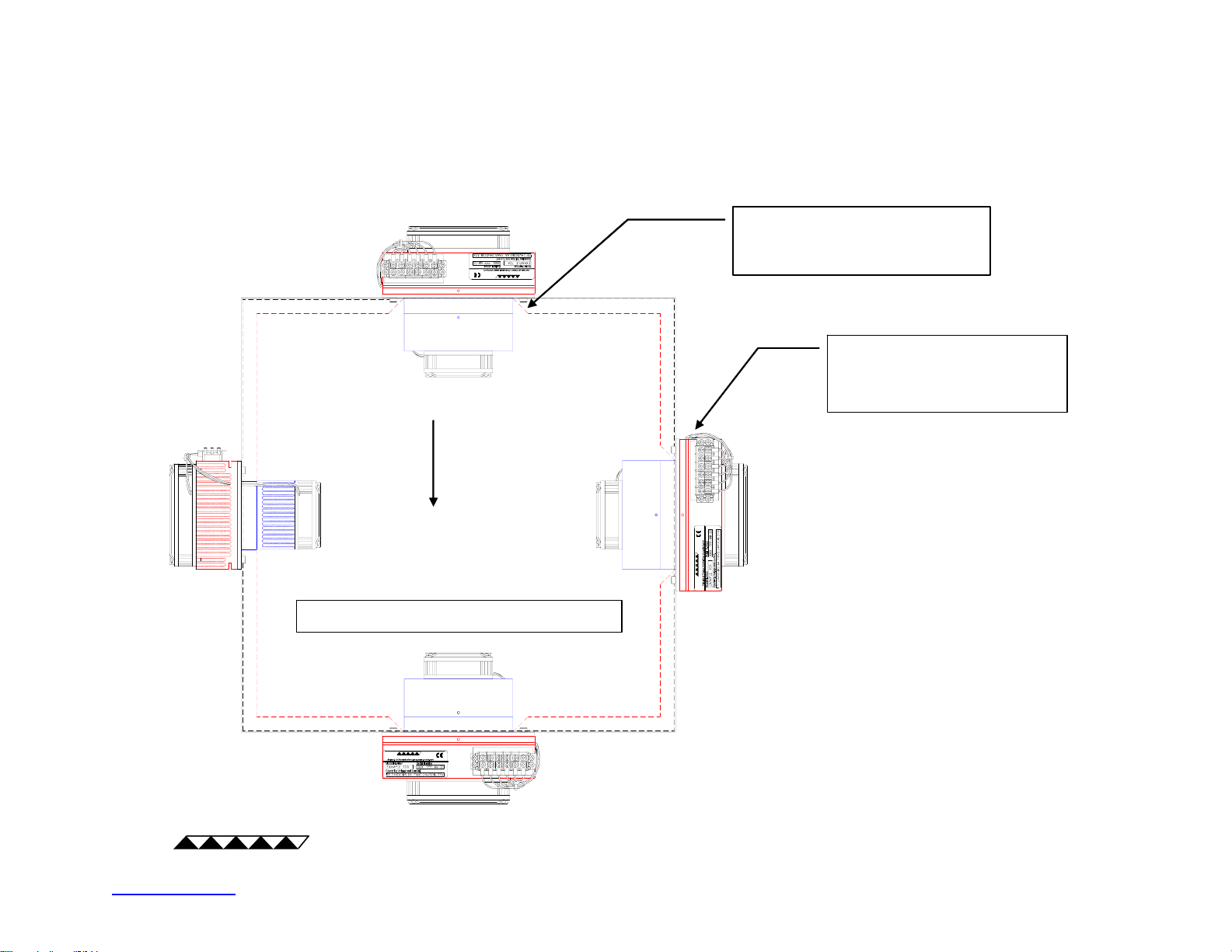
TCA Orientation
TETECHNOLOGY, I NC.
DIRECTION
OF GRAVITY
TCA can function in any orientation
Bevel opening as necessary to
allow unrestricted air flow from
cold sink
Recommended orientation
when condensat ion on TCA
cold surfaces is possible
Note:
1) When mounting LC-xxx TCA, orient and
position TCA to protect other sensitive
TETECHNOL OGY, INC.
equipment (if applicable) from unexpected
leaks.
2) If TCA cold surfaces are below the dewpoint temperature, condensate should be
prevented from contac t sensitive
equipment and points of electric al contact.
TE
http://www.tetech.com email: [email protected]
TECHNOLOGY, INC
13/22
TETECHNOLOGY, INC.
Page 14
.
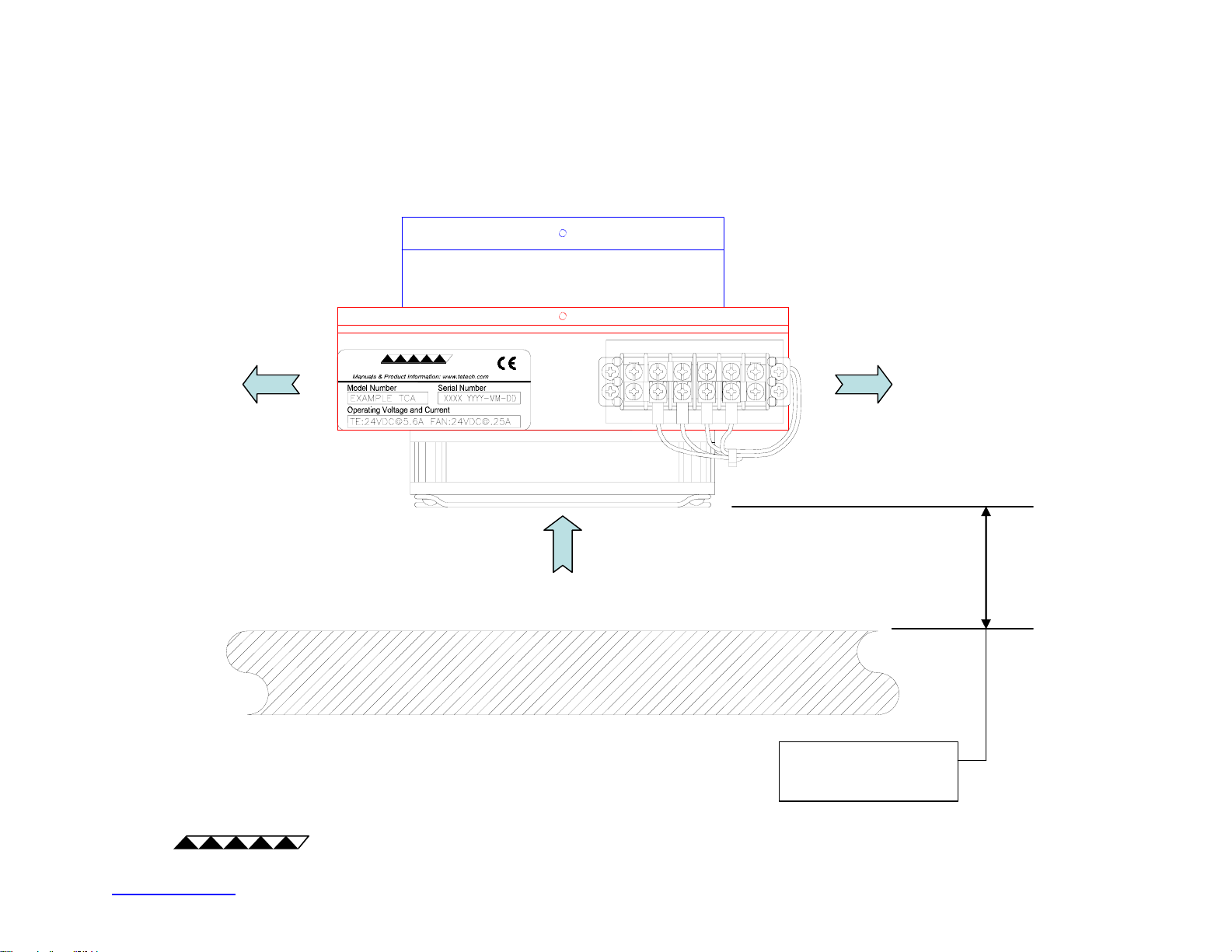
Minimum Distance between Fan and Obstruction
TETECHNOLOGY, INC.
AIR FLOW
TE
http://www.tetech.com email: [email protected]
TECHNOLOGY, INC
14/22
>45 mm
for best pe rformance
Page 15
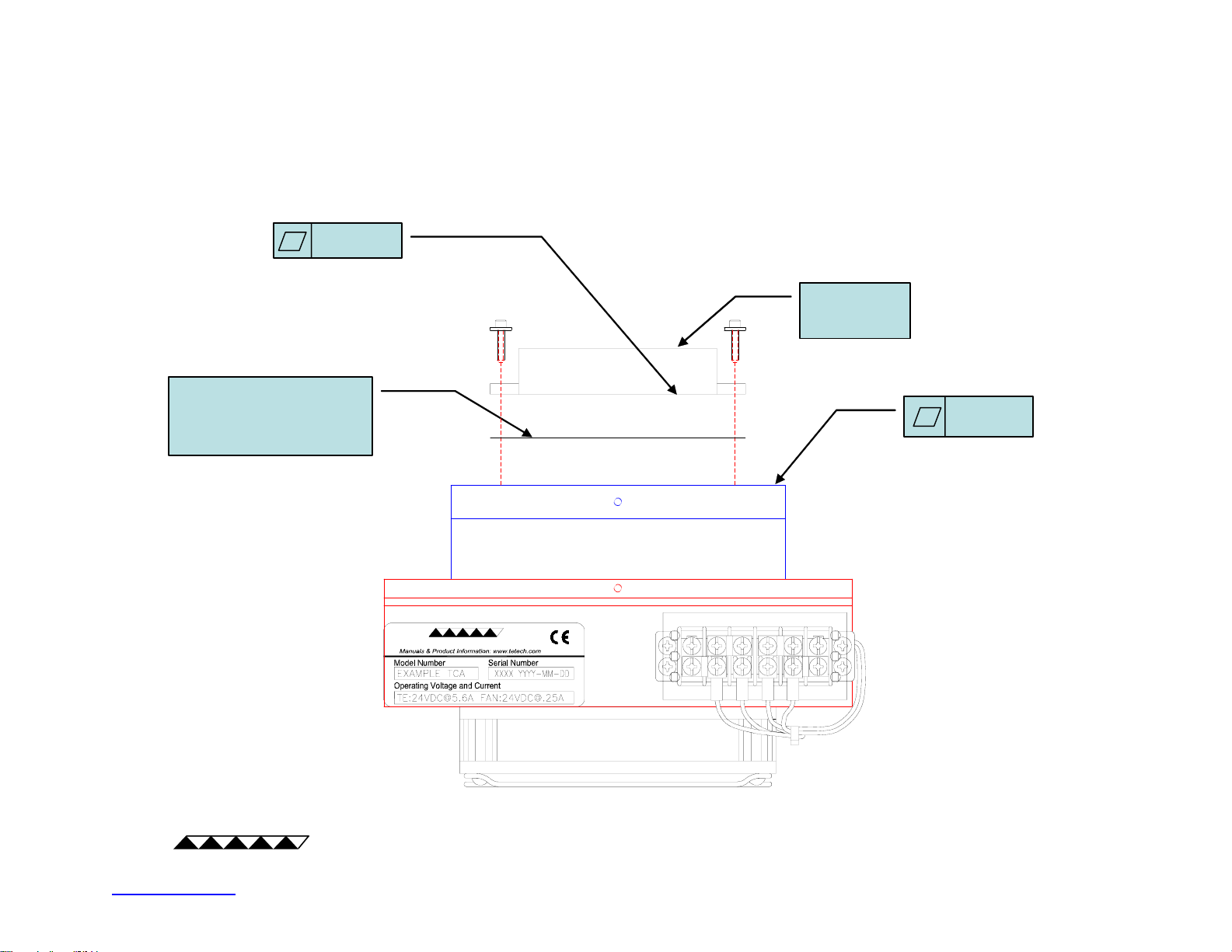
.
0.05 mm
recommended
Thermal Interace
Material (pad or
grease)
Attaching Part to CP-xxx TCA
Part to be
cooled
0.05 mm
TE
http://www.tetech.com email: [email protected]
TECHNOLOGY, INC
15/22
TETECHNOLOGY, INC.
Page 16
.
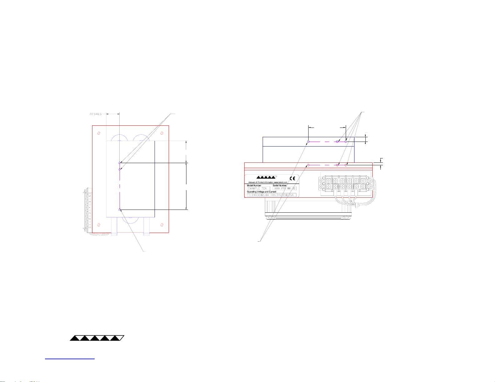
Allowable Locations for Adding Holes for Mounting
Protective Devices
Typical LC-xxx TCA
SUPPLIED HOLE FOR MOUNTING TEMPERATURE
SENSOR OR OTHER PROTECTIVE DEVICE
USER ADDED HOLES
Ø4 mm MAXIMUM, 9.7 MM DEEP MAXIMUM
DO NOT BREAK THROUGH
25 mm, MINIMUM
AS REQUIRED
SUPPLIED HOLE FOR MOUNTING TEMPERATURE
SENSOR OR OTHER PROTECTIVE DEVICE
(LOCATION MAY VARY)
Typical CP-xxx or AC-xxx TCA
TETECHNOLOGY, INC.
AS REQUIRED
USER ADDED HOLES
Ø4 mm MAXIMUM,
9.7 MM DEEP MAXIMUM
AS REQUIRED
AS REQUIRED
Notes:
TE
http://www.tetech.com email: [email protected]
TECHNOLOGY, INC
1. All dimensions in millimeters.
2. Clamp directly to base of heat sink when adding holes to heat sink; clamp directly to cold side (base of cold sink, cold
plate, or liquid heat exchanger) when adding holes to cold side. Do not apply compressive force from the heat sink to
the cold side.
3. Locations for protective devices other than those shown here may be acceptable. Contact TE Technology. for
assistance with locating a protective device elsewhere on the TCA.
16/22
Page 17

.
Configuration
Electrical Connections:
! Only use wires, electrical cables, and connectors that have proper electrical
insulation for the operating voltages and sufficient capacity for the electrical
current required.
! Be certain that all electrical components are in good condition. Do not pinch or
damage any wires when installing or operating the TCA. Operate only with the
terminal block cover in place to prevent accidental contact with equipment
carrying hazardous voltages.
! The electrical input to the TCA must be fused appropriately to prevent injury in
the event of an electrical malfunction.
! Use wire leads which are short in length to reduce the risk of electromagnetic
interference. Use electrical shielding and ferrite beads as necessary.
! The application of incorrect voltage to the TCA can result in a hazard or
damage to the TCA and/or secondary equipment.
! The electrical connections and wires of the TCA and secondary equipment
should be restricted from being cooled below the dew point.
! Do not exceed the specified electrical ratings of the TCA.
Temperature Controller and Power Supply Connections:
! For all electrical connection types shown below, the fans should be operated
at their nominally rated voltage. Consult TE Technology, Inc. for operating fans
above or below nominally rated voltage.
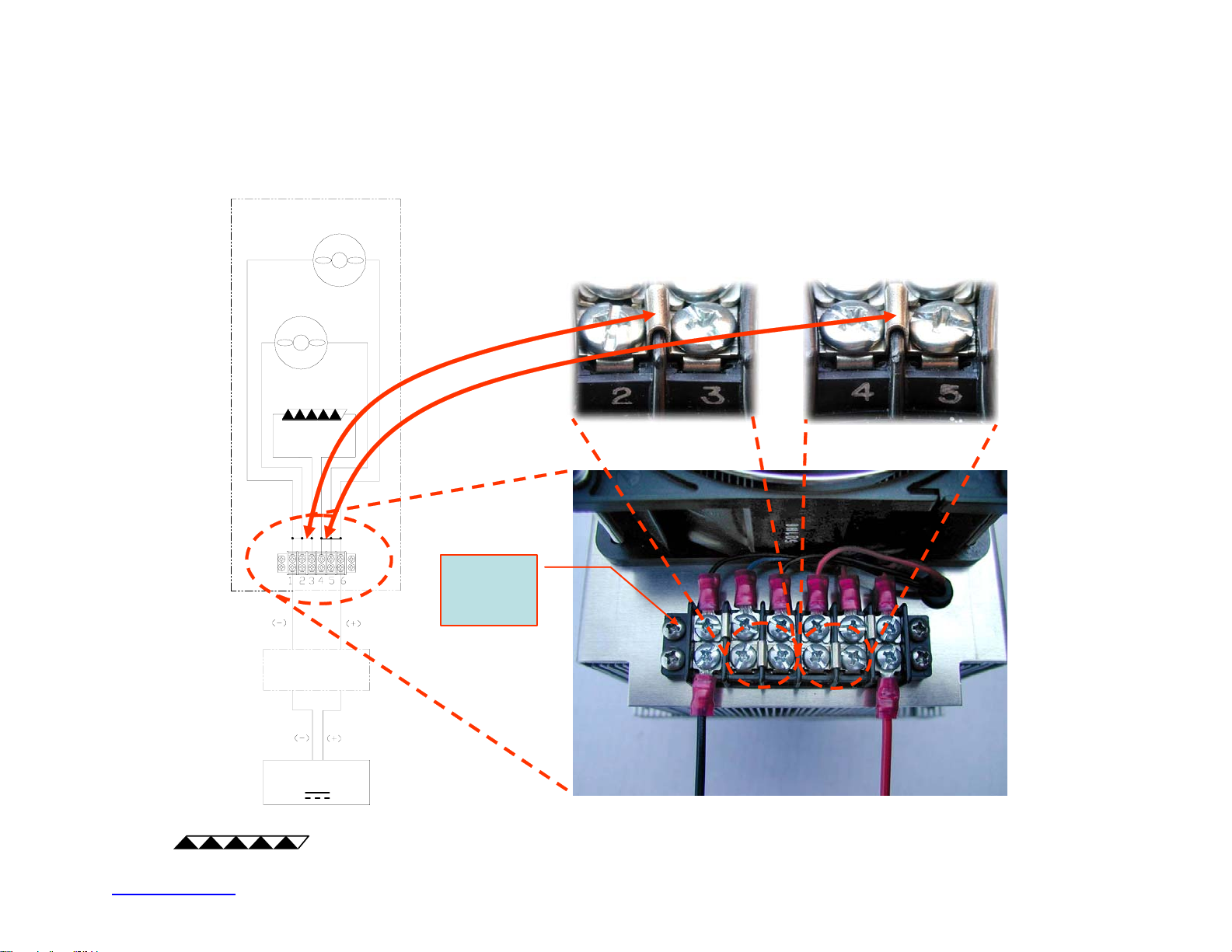
• “Single Power Supply, Constant Voltage Connection” may be used for
cooling applications only.
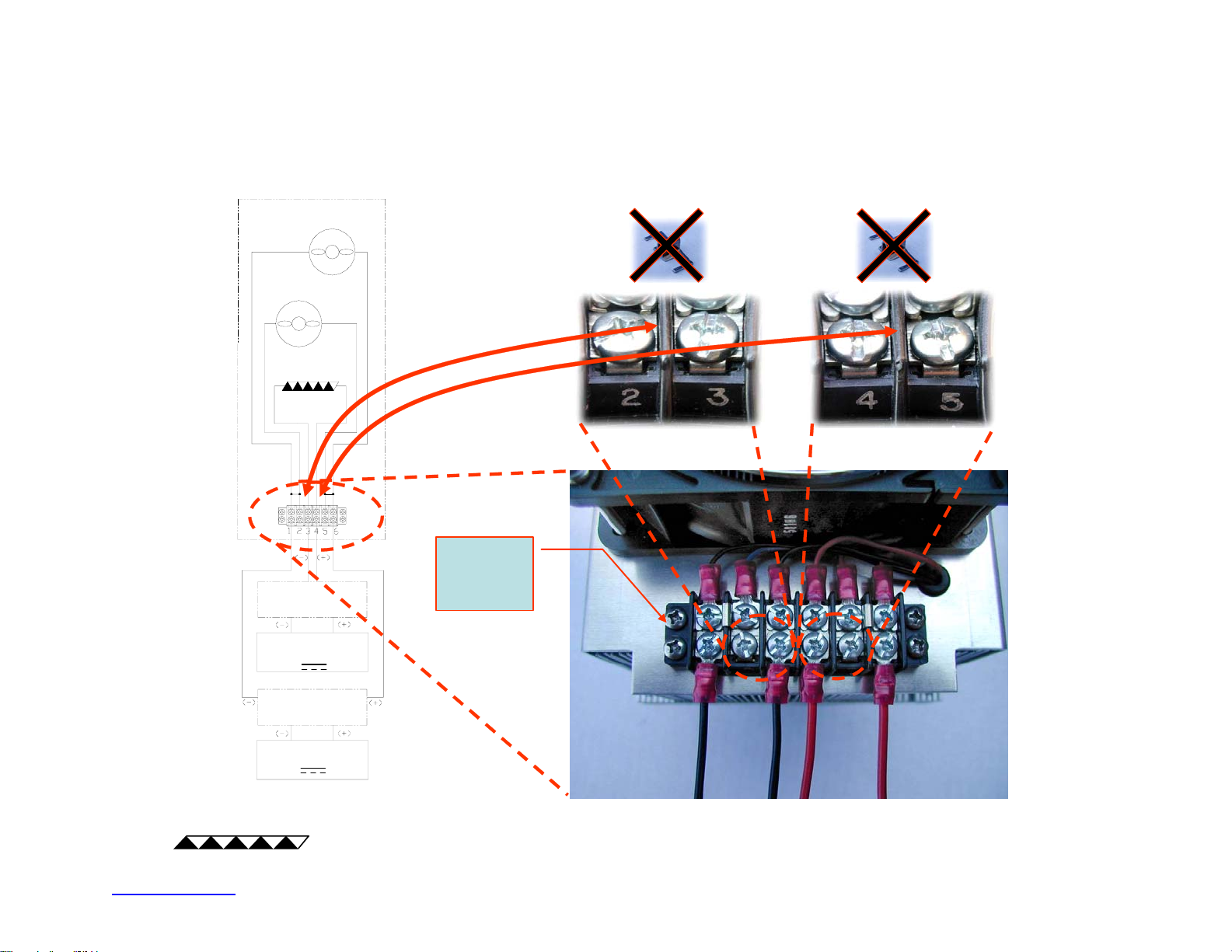
• “Two Power Supplies, Variable Heating/Cooling Connection” may be
used with two separate power supplies: one constant voltage power
supply for the fans and one variable or constant voltage power supply
for the thermoelectric (Peltier) modules. It may be used for heating or
cooling.
• “Temperature Controller Connection” may be used with one power
supply and one temperature controller (unless otherwise specified by
the controller manual). Power supply powers the fans directly and
supplies power to the controller, which then modulates power to the
TCA thermoelectric (Peltier) modules to maintain a set temperature. It
may be used for heating or cooling.
TE
http://www.tetech.com email: [email protected]
TECHNOLOGY, INC
17/22
Page 18
.
TCA
COLD-SIDE FAN
(AC-XXX UNITS ONLY)
HOT-SIDE FAN
(ALL UNITS)
THERMOELECTRIC
(PELTIER)
Single Power Supply, Constant Voltage Connection
Review electrical jumper connections. Install electrical jumpers as required.
Terminal Block
Cover removed
for clarity. Re-
install before
operation.
PROTECTION
DEVICES
DC
POWER SUPPLY
TE
http://www.tetech.com email: [email protected]
TECHNOLOGY, INC
18/22
Page 19
.
Two Power Supplies, Variable Heating/Cooling Connection
TCA
COLD-SIDE FAN
(AC-XXX UNITS ONLY)
HOT-SIDE FAN
(ALL UNITS)
THERMOELECTRIC
(PELTIER)
PROTECTION
DEVICES
Review electrical jumper c onn ections. Remove elec trical jumpers as required.
Terminal Block
Cover removed
for clarity. Re-
install before
operation.
DC CONSTANT OR
VARIABLE POWER
SUPPLY
PROTECTION
DEVICES
DC POWER SUPPLY
TE
http://www.tetech.com email: [email protected]
TECHNOLOGY, INC
19/22
Page 20
.
Temperature Controller Connection
TCA
COLD-SIDE FAN
(AC-XXX UNITS ONLY)
HOT-SIDE FAN
(ALL UNITS)
THERMOELECTRIC
(PELTIER)
TEMPERATURE
CONTROLLER
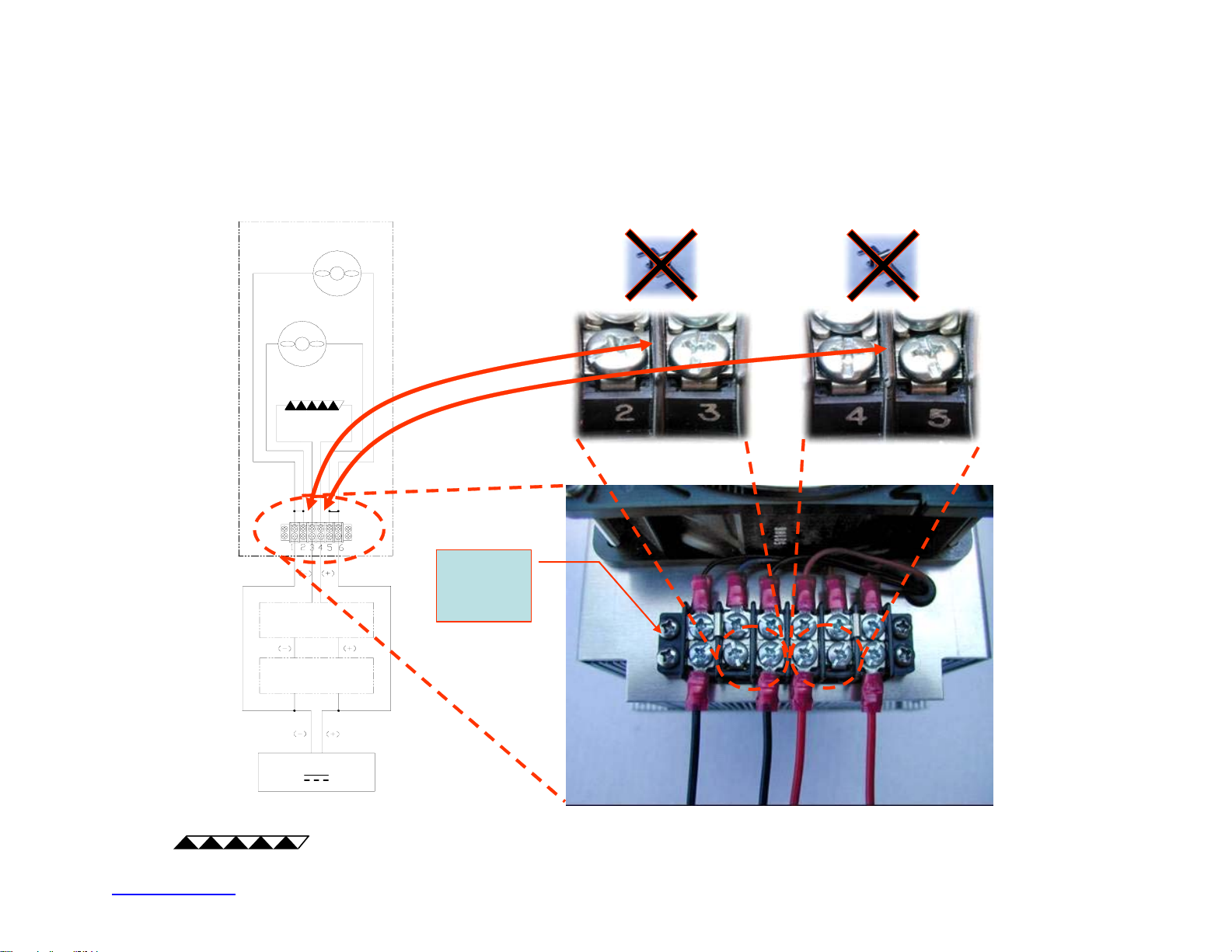
Review electrical jumper connections. Remove electrical jumpers as required.
Terminal Block
Cover removed
for clarity. Re-
install before
operation.
PROTECTION
DEVICES
DC POWER SUPPLY
TE
http://www.tetech.com email: [email protected]
TECHNOLOGY, INC
20/22
Page 21

.
The preceding temperature controller and power supply connections are
generally applicable to our standard products. Custom products, of course, might
not necessarily follow the same conventions or connection type. However, the
same principles generally apply. That is, if you are using a temperature controller
with the TCA, the temperature controller should be modulating power to the
thermoelectric modules only. The temperature controller should NOT be used to
modulate power directly to the fans.
TE
http://www.tetech.com email: [email protected]
TECHNOLOGY, INC
21/22
Page 22

.
Operation
Review the TCA product specification sheet and verify that the input voltage to
the TCA is appropriate. Verify that the power supply used with the TCA can
provide sufficient current. Use direct current only; do not use alternating current
unless otherwise specified by the TCA.
Be sure to follow the instruction manuals for the power supply and any
temperature controller used with the TCA.
Check for proper electrical connections. If you notice discoloration or abnormally
high operating temperatures on the wires and/or connectors, de-energize the
TCA and rectify the fault before re-energizing the TCA.
If using a temperature controller that provides pulse-width modulated output to
the thermoelectric (Peltier) modules, the pulse-width modulation frequency
should be between 300 Hz and 3,000 Hz.
Use analog output to power the TCA fans; do not use pulse-width modulated
output unless otherwise specified by the TCA specification sheet.
The actual TCA performance may vary by +/-10% from that shown in the TCA
specification sheet. Furthermore, specifications are based on the assumption of
unrestricted airflow to the fans and from the heat sink and cold sink (as
applicable to the TCA). It is further assumed that the TCA operates in standard
air and barometric pressure (101 kPa). Consult TE Technology, Inc. if the TCA is
to operate with some known airflow restriction and/or the TCA is to operate in a
non-standard gas and/or pressure.
While in operation, look for any non-operating fans or unexpected changes in fan
speed. If non-operating fans or unexpected fan speed changes are found, deenergize the TCA and inspect for improper electrical connections, failed or failing
fans, or unexpected air restrictions. Do not re-energize the TCA until the fault has
been rectified.
If you are using a custom TCA where fan(s) are not provided as part of the
assembly, be sure that the method you have chosen for dissipating waste heat is
adequate and operating correctly.
Review the frequently asked questions (FAQ & Technical information) and other
related documents posted at http://www.tetech.com.
Consult TE Technology if additional clarifications are needed.
TE
http://www.tetech.com email: [email protected]
TECHNOLOGY, INC
22/22
 Loading...