


 Loading...
Instruction Manual
for
Model TC-720
and
Model TC-720 OEM
Thermoelectric Cooler
Temperature Controller
August 11, 2014
Drawing #5252 Rev. A
TE ®
TECHNOLOGY, INC.
1590 Keane Drive |
Phone: (231) 929-3966 |
Traverse City, MI 49696 USA |
Fax: (231) 929-4163 |
www .tetech .com |
e-mail: cool@tetech.com |
All Materials Copyright © 2013, 2014, TE Technology, Inc.

General Safety Warnings
 This manual must be read and followed carefully before installation and operation. All warnings in this Instruction Manual apply to both the TC-720 and TC-720 OEM versions of the controller. Where “TC-720” is referenced, it is used generically and interchangeably for both the TC-720 and the TC-720 OEM versions of the controller, except where otherwise specifically noted.
THE LATEST REVISION OF THIS MANUAL IS AVAILABLE AT www.tetech.com. Verify that you are using the latest revision available.
Do not use in an explosive or potentially explosive environment.
The TC-720 is designed specifically for its intended purpose of providing temperature control of TE Technology’s thermoelectric devices only. The temperature controller is intended for light industrial, laboratory, or similar use; it is not intended for household or medical use.
Do not use the TC-720 to control capacitive or inductive loads as this could damage and/or overheat the controller. Examples of capacitive or inductive loads include but are not limited to motors and solenoids.
Do not use if the controller has been damaged.
Only qualified technicians should install this controller.
Do not allow the electrical connections or components on the printed circuit board, including those on the reverse side of the JP3, JP5, JP6 and JP7 connectors, to touch any electrically conductive surfaces.
Do not operate in an environment where the controller could come in contact with condensation, water, metal shavings, dirt or other contaminants, or electrically conductive materials.
Use ESD (Electro Static Discharge) protection when installing or handling the controller.
Do not touch any of the electrical connections or components of the TC-720 while the controller is energized. Doing so can disrupt the function of the controller.
The printed circuit board underneath JP7 and exposed components on the printed circuit board could exceed 70 °C under normal operation. Use caution! Protect against accidental contact with hot surfaces.
Improper tuning of this temperature controller can lead to overheating of the load (e.g. cooling assembly, heater, etc.) and other related equipment.
Use protection devices to prevent hazardous conditions and/or damage to equipment.
Each power input that is used must be fused separately. Alternately, a power supply with integral over current protection can be used if it is appropriately sized for protecting the controller/TE device.
Thermoelectric devices are capable of developing potentially hazardous temperatures and/or other potentially hazardous conditions. Read and follow the instructions in TE Technology’s Thermoelectric Cooling Assembly (TCA) Instruction manual before using this controller. If using a thermoelectric device from another manufacturer, read and follow all instructions pertaining to that manufacturer’s device before operating the controller. The (TCA) Instruction manual is available for download from TE Technology's website at www.tetech.com.
2
For more information regarding protection devices read TE Technology’s Thermoelectric Cooling Assembly (TCA) Instruction manual which is available for download from TE Technology's website at www.tetech.com. The terms and provisions relating to protection devices as provided in the TCA Instruction manual are hereby incorporated by reference. A copy of the TCA Instruction manual can also be sent via regular mail upon request.
TE Technology, Inc. does not make any warranty, expressed or implied, that the use or operation of the equipment will be functional or effective if the equipment is not installed and used in accordance with this manual.
TE Technology, Inc. shall not be liable, and Purchaser shall defend, hold harmless, and indemnify TE Technology, Inc. from and against, any losses, costs, expenses (including reasonable attorneys’ fees), injuries, liabilities or damages of any kind or nature whatsoever, arising out of the use or inability to use this TE Technology, Inc. product, from the omission or failure to use protection devices, or from failure to comply with this manual. This provision is in addition to any other indemnification provisions which are a part of the Purchase Order or contract with Purchaser.
All specifications are subject to change without notice.
3
|
Table of Contents |
|
License Agreement ......................................................................................................................... |
5 |
|
FEATURES........................................................................................................................................ |
8 |
|
1.0 |
SETUP ................................................................................................................................. |
14 |
2.0 |
DISPLAY AND MENU OPTIONS........................................................................................... |
28 |
3.0 |
Controller Tuning ............................................................................................................... |
39 |
4.0 |
Controller Software and USB Communication .................................................................. |
41 |
Controller Schematic..................................................................................................................... |
62 |
|
Troubleshooting Controller .......................................................................................................... |
63 |
|
TC-720 Electrical Connections ...................................................................................................... |
66 |
|
TC-720 Mechanical Package Drawing........................................................................................... |
67 |
|
TC-720 OEM Mechanical Package Drawing .................................................................................. |
68 |
|
APPENDIX A-Thermistors Available for TC-720 ............................................................................ |
69 |
|
Appendix B - USB Communications .............................................................................................. |
74 |
|
Appendix C – Programming Custom Sensor Curves ..................................................................... |
92 |
|
Appendix D – Programming Ramp/Soak Routines ....................................................................... |
96 |
|
Appendix E – Additional Notes on Fan Control ............................................................................ |
98 |
|
4
TE TECHNOLOGY, INC. (TE TECH)
License Agreement
CAREFULLY READ THE FOLLOWING TERMS AND CONDITIONS BEFORE OPENING THIS PACKAGE OR SIGNIFYING YOUR ACCEPTANCE BY CLICKING THE APPROPRIATE DIALOG BOX. OPENING THIS PACKAGE, CLICKING THE APPROPRIATE DIALOG BOX OR USING ANY PART OF THE SOFTWARE SIGNIFIES YOUR ACCEPTANCE OF (1) THESE TERMS AND CONDITIONS FOR THE LICENSED SOFTWARE, AND (2) THE TERMS OF ACCEPTANCE OF TE TECH FOR ANY PRODUCTS PURCHASED FROM TE TECH. IF YOU DO NOT AGREE WITH THEM, PROMPTLY RETURN THE PACKAGE UNOPENED AND UNUSED ALONG WITH ANY OTHER ITEM THAT WAS INCLUDED IN THE SAME PRODUCT NUMBER FOR FULL CREDIT.
You, as the Customer, agree as follows:
1.DEFINITIONS
“Application Software” shall mean those portions of the Licensed Software created by TE TECH.
“Designated Hardware” shall mean the one (1) hardware device, purchased from TE TECH, upon which Customer shall run the Licensed Software.
“Licensed Software” shall mean the Application Software plus any other software supplied by TE TECH pursuant to this Agreement.
“Third Party Software” shall mean software owned or licensed by a third party, including but not limited to operating systems that is embedded within the Licensed Software or otherwise included with any product provided to Customer from TE TECH.
2.LICENSE
2.1Except as provided in section 2.2 below, you are granted only a personal, non-transferable, nonexclusive license to use the Licensed Software only on the Designated Hardware. You may copy the Licensed Software into machine readable form for backup purposes or to support your use of the Licensed Software on the Designated Hardware. No other copies shall be made unless authorized in writing by TE TECH. You may not (i) reverse engineer, decompile, or disassemble the Licensed Software (except to the extent such foregoing restriction is expressly prohibited by applicable law); (ii) sub-license, lease, or rent the Licensed Software; (iii) distribute in part, modify, or create derivatives of the Licensed Software; (iv) amend, modify, or supplement Licensed Software with any additional code except for the purpose of further configuring the Licensed Software for use with Designated Hardware; or (v) directly or indirectly, export, re-export, download, or ship the Licensed Software in violation of the laws and regulations of the U.S. The Licensed Software, comprising proprietary trade secret information of TE TECH and/or its Licensor’s, shall be held in confidence by Customer and protected from disclosure to third parties. No title to the intellectual property is transferred, You must reproduce and include all applicable copyright notices on any copy. Licensed Software shall not be copied, reproduced, or used for any other purpose outside of operation of the TE TECH hardware, and shall not be used on any other piece of hardware other than the TE TECH hardware with, or for, which it was provided. Notwithstanding the foregoing, in the event that you download the Licensed Software from the internet without purchasing Designated Hardware, the Licensed Software may only be used for evaluation purposes and must be deleted (including all copies) within fifteen (15) days of downloading. You may not use the Licensed Software with any other equipment other than the Designated Hardware without prior written approval from TE TECH. If no operating system software is included in the software provided under this Agreement, you must make provision for any required operating system software licenses. At its option, TE TECH may, upon request, provide the source code for the Licensed Software. The limited warranty provided in section 3 below shall be null and void immediately upon TE TECH providing the source code, or any portion thereof, to you.
2.2If you are an authorized TE TECH distributor or an Original Equipment Manufacturer who incorporates the Licensed Software into your equipment for sale to an end user, or you use the Licensed Software to create redistributables, you may transfer the Licensed Software to an end user provided that the end user agrees to be bound by the provisions of this Agreement. You shall use your best efforts to enforce your agreement with customers made in accordance with this Section 2.2 and shall promptly report any violation or suspected violation to TE TECH. In the event that your customer violates any portion of this agreement, you agree to defend, hold harmless and indemnify TE TECH from any and all such claims. TE TECH may, at its option, bring suit against your customer to enforce the terms of this agreement, TE TECH’s costs and expenses incurred as a result of such action (including reasonable attorneys’ fees) shall be your responsibility.
2.3The Licensed Software may include Third Party Software licensed to TE TECH. Customer hereby acknowledges and agrees that any Third Party Software provided by TE TECH to Customer hereunder (a) shall not be modified and shall be used and/or used and redistributed or resold (to the extent permitted under Section 2.2) only embedded within the TE TECH hardware product as provided by TE TECH, (b) shall always contain and only be redistributed (to the extent permitted under Section 2.2) with all proprietary markings present as provided to Customer hereunder and under the same terms and conditions as set forth in this Agreement. All rights and benefits afforded to TE TECH under this Agreement shall apply equally to the owner of the Third Party Software (the “Third Party”) and its licensors with respect to the Third Party Software. The Third Party and its licensors are intended third party beneficiaries of this Agreement, and the provisions of this Agreement relating to the Licensed Software, as the same incorporate the Third Party Software, are made expressly for the benefit of, and are enforceable by, the Third Party and its licensors. The Third Party and its licensors retain ownership of all copies of the Third Party Software. Unless a pass-through warranty covering the Third Party Software is extended directly to you by the Third
Party, all Third Party Software is provided “AS IS” without warranty of any kind, and each Third Party and its licensors disclaim all warranties, either express or implied, including but not limited to the implied warranties of merchantability, title, non-infringement or fitness for a particular purpose with regard to the Third Party Software. The Third Party shall not have any liability for special, indirect, punitive, incidental or consequential damages.
5
2.4EXCEPT AS PROVIDED IN SECTION 2.2 ABOVE, IF YOU TRANSFER POSSESSION OF ANY COPY OF THE LICENSED SOFTWARE TO ANOTHER PARTY WITHOUT WRITTEN CONSENT OF TE TECH, YOUR LICENSE IS AUTOMATICALLY TERMINATED. Any attempt otherwise to sublicense, assign or transfer any of the right, duties or obligations hereunder is void.
2.5If the Licensed Software or associated documentation is provided to any U.S. Government entity, unit, or agency, the restrictions set forth at section 52.227-19(c) (“Commercial computer software - restricted rights”) of the Federal Acquisition Regulations (FARs) shall apply. If the Licensed Software or associated documentation is provided to the U.S. Government, Department of Defense (DOD), or any entity, unit, or agency thereof, the restrictions set forth at section 252.227-7015 (“Technical Data -Commercial Items”) of the DOD FAR Supplement (DFARS) shall also apply.
2.6For rights granted in this Agreement, Customer shall pay to TE TECH the then-current product price (license fee) for each copy of the Licensed Software provided by TE TECH to Customer.
2.7Customer shall pay all import duties and registration fees and all sales, use and excise taxes (and any other assessments in the nature of taxes however designated) on the Licensed Software or its license to use the Licensed Software, or resulting from this Agreement, exclusive of taxes based on TE TECH’s net income.
2.8Customer acknowledges that the Licensed Software, including, without limitation, TE TECH logos, trademarks and all information contained therein, is proprietary to TE TECH, is valuable, gives a competitive advantage to TE TECH, and could not, without significant expense and difficulty, be obtained or duplicated by others who have not been able to acquire the same through means expressly authorized in this agreement. You agree that, unless you first obtain the prior written consent of TE TECH ,or unless required by law, you shall not communicate or disclose, directly or indirectly, to any person or firm, or use at any time, any of the TE TECH’s proprietary information, except as provided in this Agreement. The provisions of the section, among certain others, shall survive the termination of this Agreement for whatever reason. The Licensed Software shall be and remain the exclusive property of TE TECH.
3.WARRANTY
3.1Only if Customer has purchased Designated Hardware (the purchase price of which automatically includes the license fee), TE TECH warrants that the Application Software will be in substantial conformance with the specifications in the manual pertaining thereto as of the date of shipment by TE TECH. If, within ninety (90) days of date of shipment, it is shown that the Application Software does not meet this warranty, TE TECH will, at its option, either correct the defect or error in the Application Software, free of charge, or make available to Customer satisfactory substitute software, or, as a last resort, return to Customer all payments made as license fees and terminate the license with respect to the Application Software affected. TE TECH does not warrant that operation of the Application Software will be uninterrupted or error free or that it will meet Customer’s needs. All other portions of the Licensed Software are provided “as is” without warranty of any kind.
3.2TE TECH warrants that the media on which the Application Software is delivered will be free from defects in material or workmanship under normal use and service for a period of ninety (90) days from the date of delivery. If any defects are discovered in the media is discovered and reported by Customer within ninety (90) days after delivery TE TECH shall, at no cost to Customer, upon return of same to TE TECH, replace the media and deliver (electronically) to Customer a new and complete copy of the Licensed Software.
3.3Any modification to the Licensed Software by the Customer without the express written consent of TE TECH shall void the warranty.
3.4THE FOREGOING WARRANTIES ARE EXCLUSIVE AND ARE IN LIEU OF ALL OTHER WARRANTIES WITH RESPECT TO THE LICENSED SOFTWARE WHETHER WRITTEN, ORAL, IMPLIED OR STATUTORY. NO IMPLIED OR STATUTORY WARRANTY OF MERCHANTABILITY OR FITNESS FOR A PARTICULAR
PURPOSE SHALL APPLY. NO WARRANTY ARISING FROM COURSE OF PERFORMANCE, COURSE OF DEALING, OR USAGE OF TRADE SHALL APPLY. NOTWITHSTANDING ANYTHING TO THE CONTRARY HEREIN, UNLESS CUSTOMER HAS PAID TE TECH A SEPARATE LICENSE FEE THEREFOR, TE TECH MAKES NO WARRANTIES AS TO THE LICENSED SOFTWARE, WHICH IS PROVIDED “AS IS” WITHOUT WARRANTY OF ANY KIND, WHETHER EXPRESS OR IMPLIED.
4.LIMITATION OF LIABILITY
4.1IN NO EVENT, WHETHER AS A RESULT OF BREACH OF CONTRACT, BREACH OF WARRANTY, TORT (INCLUDING NEGLIGENCE) OR OTHERWISE, SHALL TE TECH OR ITS SUPPLIERS BE LIABLE FOR ANY SPECIAL, CONSEQUENTIAL, INCIDENTAL OR PENAL DAMAGES INCLUDING, BUT NOT LIMITED TO, LOSS OF PROFIT OR REVENUES, LOSS OF USE OF THE LICENSED SOFTWARE OR ANY PART THEREOF, OR ANY ASSOCIATED EQUIPMENT, DAMAGE TO ASSOCIATED EQUIPMENT, COST OF CAPITAL, COST OF SUBSTITUTE PRODUCTS, FACILITIES, SERVICES OR REPLACEMENT POWER, DOWN TIME COSTS, OR CLAIMS OF CUSTOMER’S CUSTOMERS AND TRANSFEREES FOR SUCH DAMAGES EVEN IF TE TECH HAS BEEN ADVISED OF THE POSSIBILITY OF SUCH DAMAGES.
4.2EXCEPT AS PROVIDED IN SECTION 5, INDEMNITY, IN NO EVENT, WHETHER AS A RESULT OF BREACH OF CONTRACT OR WARRANTY, TORT (INCLUDING NEGLIGENCE) OR OTHERWISE, SHALL TE TECH’S LIABILITY TO CUSTOMER FOR ANY LOSS OR DAMAGE ARISING OUT OF, OR RESULTING FROM THIS AGREEMENT, OR FROM ITS PERFORMANCE OR BREACH, OR FROM THE LICENSED SOFTWARE OR ANY PART THEREOF, OR FROM ANY SERVICE FURNISHED HEREUNDER, EXCEED THE QUOTED CHARGES FOR THE LICENSED SOFTWARE. ANY SUCH LIABILITY SHALL TERMINATE UPON THE TERMINATION OF THE WARRANTY PERIOD AS SET FORTH IN SECTION 3.
4.3If TE TECH furnishes Customer with advice or other assistance which concerns Licensed Software or any portion thereof supplied hereunder or any system or equipment on which any such software may be installed and which is not required pursuant to this Agreement the furnishing of such advice or assistance will not subject TE TECH to any liability, whether in contract, warranty, tort (including negligence) or otherwise.
6
4.4 The products (hardware and software) to be licensed or sold hereunder are not intended for use in any application specifically prohibited in writing by TE TECH, including, without limitation, in any nuclear, chemical or weapons production facility or activity, or other activity where failure of the products could lead directly to death, personal injury or severe physical or environmental damage. If so used, TE TECH disclaims all liability for any damages arising as a result of the hazardous nature of the business in question, including but not limited to nuclear, chemical or environmental damage, injury or contamination, and Customer shall indemnify, hold harmless and defend TE TECH, its officers, directors, employees and agents against all such liability, whether based on contract, warranty, tort (including negligence), or any other legal theory, regardless of whether TE TECH had knowledge of the possibility of such damages.
5.INDEMNITY
5.1Should the Application Software be held by a court to constitute patent or copyright infringement and its use is enjoined, TE TECH shall, at its expense and option, either procure for Customer the right to continued use, or replace same with a non-infringing product or part, or modify the Application Software so that it becomes non-infringing, or remove the software and refund the license charge pertaining thereto (less reasonable depredation for any period of use) and any transportation costs separately paid by Customer. The foregoing states the entire liability of TE TECH for patent and copyright infringement by the Licensed Software or any part thereof.
5.2The indemnity under the preceding paragraph shall not apply to any use of Application Software in conjunction with any other product in a combination not furnished by TE TECH as a part of this transaction. As to any such use in such combination, or any improper or unauthorized use, installation, or operation of the Application Software, TE TECH assumes no liability whatsoever for patent and copyright infringement and Customer will hold TE TECH harmless against any infringement claims arising there from (including, but not limited to, reasonable attorney’s fees).
6.TERM AND TERMINATION
6.1You may terminate the license granted hereunder at any time by destroying the Licensed Software together with all copies thereof and notifying TE TECH in writing that all use of the Licensed Software has ceased and that same has been destroyed.
6.2TE TECH, upon thirty (30) days’ notice, may terminate this Agreement or any license hereunder if Customer fails to perform any obligation or undertaking to be performed by it under this Agreement or if Customer attempts to assign this Agreement without the prior written consent of TE TECH. Within twenty (20) days after any such termination of this Agreement, Customer shall certify in writing to TE TECH that all use of the Licensed Software has ceased, and that same has been returned or destroyed, in accordance with TE TECH’s instructions.
6.3Sections 4, 6 and 7 of this Agreement shall survive any expiration or termination and remain in effect. Termination of this Agreement or any license hereunder shall not relieve Customer of its obligation to pay any and all outstanding charges hereunder nor entitle Customer to any refund of such charges previously paid.
7.IMPORT/EXPORT
7.1If you intend to import or export (or re-export), directly or indirectly, whether electronically or otherwise, the software products or technical data relating thereto supplied hereunder or any portion thereof, it is your responsibility to assure compliance with U.S. and other applicable governmental import and/or export control laws and, if appropriate, to secure any required licenses or approvals in your own name. You are also responsible for the accuracy and completeness of any information or certification you provide for purposes of import or export control compliance.
8.GENERAL
8.1This Agreement shall be governed by the laws of the State of Michigan, without regard to its conflict of law provisions. You agree that any civil action or claims which relate to this Agreement or the Licensed Software must be brought and maintained in a court of competent jurisdiction located in Grand Traverse County, Michigan, or, alternatively, the U.S. District court for the Western District of Michigan. You hereby waive venue in any other forum. The provisions of the United Nations Convention on the International Sale of Goods shall not apply to this Agreement
8.2Should you have any questions concerning this Agreement, contact TE TECH by writing to: TE TECHNOLOGY, INC., 1590 KEANE DRIVE, TRAVERSE CITY, MI 49696.
8.3YOU ACKNOWLEDGE THAT YOU HAVE READ THIS AGREEMENT, UNDERSTAND IT AND AGREE TO BE BOUND BY ITS TERMS AND CONDITIONS. YOU FURTHER AGREE THAT IT IS THE COMPLETE AND EXCLUSIVE STATEMENT OF THE AGREEMENT BETWEEN US AND SUPERSEDES ANY PROPOSAL OR PRIOR AGREEMENT, ORAL OR WRITTEN, AND ANY OTHER COMMUNICATIONS BETWEEN US RELATING TO THE SUBJECT MATTER OF THIS AGREEMENT. FURTHER, NO CHANGE OR AMENDMENT TO THIS AGREEMENT SHALL BE EFFECTIVE UNLESS AGREED TO BY WRITTEN INSTRUMENT SIGNED BY A DULY AUTHORIZED REPRESENTATIVE OF TE TECH.
7

FEATURES
TC-720 Temperature Controller
The TC-720 is a bipolar temperature controller capable of automatically reversing power to Peltier thermoelectric (TE) devices to provide heating or cooling as required to maintain a specific set point temperature. It incorporates a keypad and a liquid-crystal display housed in a die-cast aluminum box. The display allows the user to monitor the sensor temperatures, output level, alarm conditions, and menu settings. The integrated keypad accesses an easy-to-use menu system, allowing the user to adjust all of the basic controller parameters such as the set temperature, tuning parameters, and alarm parameters.
The controller can also be connected to a computer via a USB port for advanced programming, data graphing, and data logging. All of the controller parameters, including the advanced parameters which are not adjustable through the keypad, can be adjusted with the included software and saved to EEPROM. The command set for the controller is also provided which allows the creation of custom software applications using National Instruments LabVIEW, for example.
8
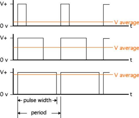
PULSE-WIDTH MODULATED POWER OUTPUT WITH SOFT START
The TC-720 regulates the output power to the TE device using a method called pulse-width modulation (PWM). With PWM, power to the TE device is switched quickly on and off at a constant frequency. This creates a square wave pulse of power with a constant time period. The on time, or pulse width, can be varied to create an average output voltage (Vaverage) that is required by the TE device to maintain the set temperature.
The important advantage to PWM control is that it does not cause the extreme temperature excursions that are experienced with a thermostatic control system. This helps to extend the life and reliability of the TE device. At the same time, PWM control does not generate a large amount of waste heat as compared with most linear control systems, so large heat sinks are not required with the PWM temperature controller. The controller features a soft-start function that slowly increases the output when enabled to prevent current surges or spikes at start up.
By choosing the appropriate power supply(s), the controller can control loads from 0 to ≤36 V DC at up to 20 A via pulsewidth modulation with the onboard power transistors arranged in an H-bridge. This enables bipolar control for automatically adjusting the output voltage for heating or cooling.
LINEAR CONTROL OUTPUT
A potential disadvantage to PWM control is the generation of electromagnetic noise, particularly in high current applications. In such cases, the TC-720 can be configured as part of a linear control system to provide (1) a proportional analog output signal, and (2) a means of reversing the polarity of a drive voltage generated by an external power supply. The analog signal cannot be used for powering TE devices directly, but it can be used with a programmable, linear-output power supply. In this mode the analog output from the TC-720 controls the load-level output voltage of the linear power supply. That linear output voltage can be fed back into the TC-720 where its electronic circuitry (H-bridge) is used to control the polarity of the voltage which is then supplied to the TE device. This provides true bipolar, linear control.
9
One such power supply that accepts an analog input is the Cotek AE series programmable switching power supplies (http://www.cotek.com.tw/). These power supplies accept a 0 to 5 volt input signal which causes the output voltage of the power supply to vary from 0 V to its full-scale voltage. The controller’s analog output signal can also be modified to limit its output signal which, in turn, will limit the output voltage from the power supply.
RAMP / SOAK PROGRAMMING (BETA FEATURE)
The controller has a built in ramp and soak capability that provides eight different steps programmable as ramp or hold (soak) functions. Each step can be repeated or groups of steps can be repeated multiple times. This is useful in creating a multi-step procedure with various temperatures and times for complicated processes or tests.
PROGRAMMABLE, ENERGY SAVING, CONTROL MODE FOR COOLING AND HEATING ENCLOSURES
This control mode provides an energy efficient method for controlling the temperature in an enclosure only when truly needed yet provides greater capability and thermoelectric cooler life than what an ON/OFF or dead band control mode could provide. This mode allows the user to select a three different temperature ranges: (1) a temperature range where no cooling or heating is needed and no output power is sent to the TE Device, (2) a temperature range whereby the controller will proportionally increase cooling power as the temperature increases, and (3) a temperature range whereby the controller will proportionally increase heating power as the temperature decreases.
TWO ALARM OUTPUTS
Two individual alarm outputs, each capable of sinking up to 2 A of current, are provided. These alarms can be triggered based on sensor temperatures.
MULTI-SPEED FAN CONTROL OR OTHER LOAD CONTROL
The Alarm 1 output can be configured to provide PWM speed control of a fan (fan must be specifically designed for speed control) with several customizable settings. Speed control is programmable as a function of the main controller’s output power, and the control points are programmable via software. For example, the fan can be run at high speed only when increased cooling capacity is needed, and at a low speed or off when the cooler is operating at a low capacity. The polarity of the output signal can be reversed, so both two wire and three wire PWM controllable fans can be used. The PWM output frequency can be adjusted to make it adaptable to a wide range of fans.
The fan speed control includes a setting to give the fan 100% power for a user-programmable number of seconds when the output is first turned on. This operates the fan at full power to make sure the fan is spinning before reducing power. This is most useful when low output levels are chosen.
USER PROGRAMMABLE SENSORS
In addition to the pre-programmed thermistor curves, a user programmable sensor is available. Through the computer program a custom sensor curve (look-up table) can be created, saved in a separate file on the computer, and uploaded to the controller. An infinite number of sensors can be created for use in the controller as sensor 1 or sensor 2.
CONTROL RANGE
The TC-720 is supplied with one MP-3193 thermistor which provides a control range from -20 °C to +100 °C. Several other thermistor types are preprogrammed into controller to provide different control ranges such as -40 °C to +70 °C, for example (when using optional thermistors). In addition, a User Programmable Sensor table can also be programmed into the controller allowing it to read temperatures as low as -327.67 °C and/or up to +327.68 °C, subject to sensor type.
OVER CURRENT ALARM
The controller can be set to turn off the output if it exceeds a set current level. The controller will attempt restarting a user-defined finite or an infinite number of times. This is useful for conditions that cause a temporarily high current level, and instead of remaining off when the condition clears the unit will resume normal operation. (NOTE: This is not an analog current limit, the circuit simply senses current levels and turns the output off if an over current condition is detected).
10
STATUS INDICATORS
The controller has three light emitting diodes (LED’s) to indicate an alarm, active computer communications, and controller operation. An alarm is indicated by the orange LED, active computer communication by the blue LED, and controller operating by the green LED.
•The alarm LED is orange and flashes on and off when there is an active alarm.
•The communication LED is blue and lights when the controller is sending or receiving data from a computer.
•The green LED (under the cover of the TC-720 and uncovered in the OEM version) blinks to indicate the controller is on and operating.
The TC-720 is available in an OEM version, model TC-720 OEM. This is a basic version of the controller for Original Equipment Manufacturers (OEM’s). It is intended to be used in locations where the controller can be protected by a secondary enclosure and where the display, keypad, and box cover are not needed. The TC-720 OEM controller is the basic control circuit from the TC-720 mounted on an aluminum plate. One MP-3193 thermistor, software, and instruction manual on CD are included with each controller.
TC-720 OEM
The TC-720 OEM uses the same main circuit board found in the TC-720. The connector numbers and wiring are the same for both versions of the controller. The Schematics, Hookup Diagrams, and Wiring Connections presented in this manual are the same for both controllers; however, only the TC-720 version of the controller is depicted for clarity.
11
MAIN FEATURES
•Single or dual power supply configurations allow a wide range of output voltages:
Single power supply configuration:
≥12 V DC, ≤36.0 V DC input, powering both controller and TE device. Dual power supply configuration:
≥12 V DC, ≤36.0 V DC at 150 mA minimum for controller circuitry ≥0 V DC, ≤36.0 V DC for TE device.
•Pulse-width modulated output: square wave, approximately 337 Hz, with soft start.
•Maximum output current: up to 20 A to thermoelectric device and up to 2.0 A per alarm circuit, 20 A maximum combined output current (Note: controller does not have internal fuse protection).
•Analog signal-level output: provides true linear power control capability when used with a programmable linear power supply.
•Bipolar (heat and cool) PID control.
•Best-case control stability ±0.01 °C (when controlling a cold plate).
•Proportional (P) bandwidth adjustment: 0.5 °C to 100.0 °C.
•Integral gain (I) adjustment: 0.00 to 10.00 repeats per minute.
•Derivative gain (D) adjustment: 0.00 to 10.00 cycles per minute.
•Built in Ramp / Soak with user programmable steps in PID mode, with separate PID parameters allowed for each program step.
•Energy-saving Proportional + Deadband control mode allows the user to program a dead band where no cooling or heating is required, then gradually applies cooling or heating power only as necessary.
•User programmable temperature sensor curve—allows for the use of a variety of thermistors or IC type sensors (LM335, for example).
•Separately selectable temperature sensor types.
•Temperature control ranges:
1.-20 °C to +100 °C using the MP-3193 thermistor supplied with the controller.
2.Additional control ranges for optional thermistors are:
a.-40 °C to +70 °C using a 5k-1 TS-141 curve.
b.-20 °C to +85 °C using the 10k-1 TS-91 curve.
c.-15 °C to +80 °C using the 10k-2 TP-53 curve.
d.0 °C to +150 °C using the 50k-1 TS-104 curve.
e.+25 °C to +199 °C using the 230k-1 TS-165 curve.
• (When using one of these control ranges, the thermistor you choose must have the same response that matches the corresponding resistance-versus-temperature curve shown in the appendix of the manual. A thermistor following the 10k-2 TP-53 curve, for example, is not a standard product offered by TE Technology and must be purchased separately from a third party. Other thermistors are available from www.tetech.com.)
3.Used defined sensor table can be used to provide a custom control range for use with different sensor types.
•Optional secondary sensor input for sensing an alarm condition.
•Two available alarm outputs, capable of sinking up to 2 A each, for triggering alarms based on the primary (control) sensor and/or secondary sensor.
•Enable/disable interlock: can be used with thermostats to shut off output power.
•Fan speed control: Alarm 1 output can be configured as a programmable PWM fan control for two-wire or threewire fans that are specifically designed for speed control.
•Operating temperature range (non-condensing, vertical orientation):
Minimum: 0 °C
Maximum: 45 °C
•Back-lit Liquid Crystal Display (LCD).
•USB (Universal Serial Bus) Interface.
12
•LED indicators for active USB communication, alarm conditions, and controller OK are included on both the TC-720 and TC-720 OEM.
•ESD protection on USB port and inputs, when using provided external earth ground connection.
•Computer programmable via USB communication. (A USB cable is required to interface with the controller, the cabled is included with the TC-720, but is not included with the TC-720 OEM.)
•Software GUI compatible with Windows is included. The command set is also included to allow the user to write custom software for the controller.
13

OPERATING INSTRUCTIONS
1.0SETUP
1.1Attach the temperature sensor at an appropriate temperature-control location. Locating the sensor at the cold side of the TE device provides better control stability than locating it at the object, liquid, or air that is to be cooled/heated. However, in doing so, there will be a temperature difference between the sensor and the object, liquid, or air that is to be cooled/heated. The temperature set point can be adjusted to compensate for this temperature difference if necessary.
If you are using a secondary temperature sensor, attach it to the appropriate location as well. The secondary sensor, for example, can be used to monitor the hot side of the TE device.
NOTE: When possible, it is recommended that at least 50 mm of the sensor’s wire be thermally connected to the surface as shown in the example below. This can be accomplished by taping the sensor wires with aluminum tape, for example. If this is not done, the sensor wires will be at a different temperature than the cold side and they will add or remove heat in the region of the sensor, making the temperature reading potentially significantly less accurate and the thermal response time slower.
In addition, the sensor itself needs to have a good thermal connection to the temperature control location. Thermal grease, such as the TP-1 from TE Technology, or other suitable thermal interface material should be applied to the interface of the sensor and temperature-control location.
14
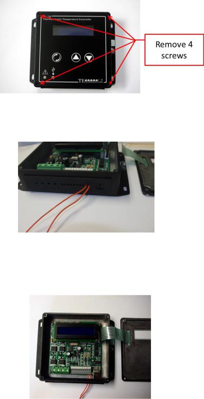
1.2To connect the sensor leads to the controller (as well as other wire connections), you will first need to open up the controller. Remove the four screws from the top of the lid. Lift the lid from the controller, and set it face down next the box.
Push the primary sensor wires through the two right-most holes in the rubber face plate located at the front side of the box. The secondary sensor wires would go through the next two holes as applicable. You may need to use a sharp tool to expand the holes before pushing the wire leads through the holes.
•Connect the primary sensor wire leads to JP2-1 (+) and JP2-2 (-).
•Connect the secondary sensor wire leads (if applicable) to JP2-4 (+) and JP2-3 (-).
•If you are using the MP-3193 or other thermistor, the polarity will not matter. See the controller hookup drawings below for further reference.
15

If you are using a thermistor for temperature sensing, the wire leads of the thermistor can be lengthened if necessary without affecting accuracy by any significant amount. However, the use of twisted pair and/or shielded wire may be required to reduce electromagnetic interference.
The TC-720 is pre-programmed to use the 15 kΩ thermistor curve as the default. The MP-3193 that comes standard with the controller is of this type. Other thermistor styles directly compatible with the controller besides the MP-3193 are available as options. See “Thermistor Styles for TC-720” in the appendix for reference or online at www.tetech.com. The controller also has numerous other thermistor curves pre-programmed, and can be programmed with a user-defined sensor curve. See the temperature vs. resistance data in the appendix for reference.
If you want to use a thermistor that has a different resistance-temperature curve from the pre-programmed thermistor curves, or if you intend to use a different type of sensor altogether, the controller should be programmed accordingly. See “Programming Custom Sensor Curves” in the appendix for instructions.
1.3The TC-720 can be used with either one or two separate DC power supplies for bipolar control of one TE device. If the maximum TE device operating voltage is less than 12 V, then two power supplies must be used with the controller. If the TE device can use a voltage ≥12 V but ≤36 V, then the controller can be used with just one power supply although using two power supplies is permitted as well.
The controller can also be set up to provide linear control output when used with a power supply whose output can be controlled with a 0 to 10 V signal (the maximum output voltage can be reduced as necessary). The power supply can then provide a power output proportional to the signal sent by the controller. This setup may reduce the overall control stability. The voltage signal from the controller is actually obtained by filtering the PWM output, and this introduces a slight delay in the control response. Also, there will be a delay in the response of the power supply since it too must process the correct power output based on the sensed voltage input from the controller.
When using one power supply for powering the controller and the TE device together, the power supply input voltage is passed directly through the controller to the TE device during the “ON” pulse. The power supply must provide a voltage that is ≥12 V but ≤36 V and provide sufficient current for the TE device and controller. The controller could be damaged if it is operated outside this voltage range. The TE device must also be capable of operating with the voltage provided by the power supply. Do NOT provide an input voltage that exceeds 36.0 V.
When using two power supplies, the input power supply for the controller itself must be ≥12 V but ≤36 V and be capable of providing at least 150 mA of current. The power supply input voltage for the TE device can be >0 V but ≤36 V and be capable of providing sufficient current.
The total maximum allowable current through the controller is 20 A (combined load and alarm current). The maximum allowable current draw for the TE device must therefore be less than 20 A depending on if and how much current is used by devices connected to the alarm outputs and the controller itself. The 20 A limit applies regardless of whether you are using one power supply or using independent power supplies for the controller and TE devices.
The controller does not have an internal fuse to limit current. Therefore, an external fuse, appropriately sized for protecting the controller/TE device, should be connected between the power supply and the controller to prevent damage to the controller/TE device and to prevent injury to the user should an overcurrent condition occur. Alternately, a power supply with integral over current protection can be used if it is appropriately sized for protecting the controller/TE device.
16

When making a cooling system from a single TE module, the maximum operating voltage for that system is usually no more than 75% of the rated Vmax of the TE module. The 75% rule is based on the TE module being thermally connected to a “good” heat sink; system modeling should be done to verify this rule is applicable though. If multiple TE modules are used in series or series-parallel combination, the Vmax of the system will be approximately 75% of the rated Vmax of each TE module multiplied by the number of modules in series. Applying a voltage greater than the system maximum will not necessarily damage the controller (unless voltage and/or current limits are exceeded), but the TE device could be damaged by overheating as a result.
Power supply and TE Device wire leads should be kept to a length of one meter or less and of sufficient wire size to reduce electrical losses in the wire and the likelihood of generating unwanted electromagnetic interference. However, see also warnings about wire length under section 1.4.
Use protection devices to prevent hazardous conditions and/or damage to the TE device and other related equipment. Protection devices must operate independently of the temperature controller circuitry. Protection devices should be placed at all points on the load and related equipment where a hazardous condition can be detected. These protection devices should de-energize the TC-720, the TE device, and, as necessary, other related secondary equipment. It is further recommended that such devices require the user to remove and correct the root cause of a fault before allowing the TC-720, the TE device, and related equipment to be re-energized. Protection devices should include, but are not limited to:
•Fuses to defend against electrical overloads
•Over-temperature and/or under-temperature thermostats to prevent against hazardous and/or damaging temperatures,
•Liquid flow meters to prevent against damage due to loss of coolant flow
The TC-720 controller (in conjunction with the standard and optional sensors) can detect undertemperature and over-temperature conditions, and it can be configured to de-energize the load when such a condition is detected. However, hazards and/or risk of loss or damage to the cooling assembly and/or secondary equipment could still occur if the temperature controller and/or sensors were to malfunction. Therefore, independent, redundant protection devices are recommended in addition to the safeguards provided by the temperature controller. For the purposes of this manual the temperature controller and sensors are not considered protection devices.
Protect the USB circuitry from unwanted Electrostatic Discharge (ESD) by either (a) plugging the USB port with the supplied USB dummy plug when not in use (TC-720), or (b) otherwise providing shielding via an enclosure or other external design feature (TC-720 OEM).
Use the supplied rubber face plate gasket to prevent wires from abrading and shorting against metal case (TC-720 only) and to protect the user from inadvertently contacting the circuit board.
17

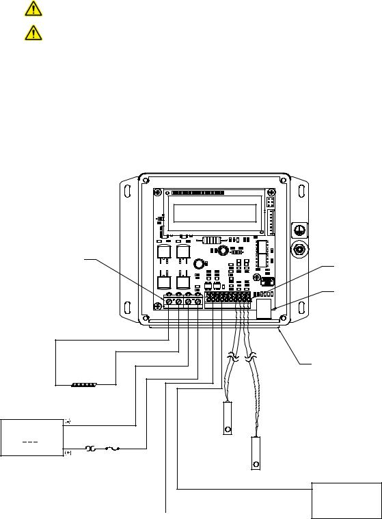
1.3.1ONE POWER SUPPLY OPERATION:
Make sure the power supply is NOT energized while making electrical connections to the controller.
The output voltage of the TE Power Supply should not exceed the maximum desired input voltage of the thermoelectric device, or the rated input voltage of the cooling assembly.
Connect the DC voltage power supply (output voltage: ≥12 V but ≤36 V) to the controller as follows:
a)Connect wire between Positive (+) terminal of the power supply and JP7-4.
b)Connect wire between Negative (-) terminal of the power supply and JP7-3.
c)See Section 1.4 for further information on connecting the TE device.
JP7 |
|
|
|
|
|
|
|
|
|
|
|
|
PIN 1 |
|
|
|
|
|
|
|
|
|
|
|
|
|
JP7 |
1 |
2 |
3 |
4 |
JP2 10 9 8 7 |
6 |
5 |
4 |
3 |
2 |
1 |
to JP7-1 |
|
|
|
|
|
|
|
|
|
|
|
|
|
to JP7-2 |
|
|
|
|
|
|
|
|
|
|
|
TE DEVICE |
|
|
|
|
|
|
|
|
|
|
|
|
(+) |
(-) |
|
|
|
|
|
|
|
|
|
|
|
|
|
|
|
|
|
OPTIONAL |
|
|
|
|
|
|
|
|
|
|
|
SECONDARY |
|
|
|
|
|
|
|
|
|
|
|
|
|
SENSOR |
|
|
|
|
|
|
DC |
to JP7-3 |
|
|
|
JP2-4 (+) and |
|
|
|
|
|
|
|
|
|
|
|
JP2-3 (-) |
|
|
|
|
|
|
||
|
|
|
|
|
|
|
|
|
|
|
||
POWER SUPPLY |
|
|
|
|
|
|
|
|
|
|
|
CONTROL |
|
|
|
|
|
|
|
|
|
|
|
|
|
≥12 V,≤36 V, 20 A maximum |
to JP7-4 |
|
|
|
|
|
|
|
|
|
|
SENSOR |
|
|
|
|
|
|
|
|
|
|
JP2-1 (+) and |
||
|
OPTIONAL FUSE |
|
|
|
|
|
|
|
|
|
|
JP2-2 (-) |
|
THERMOSTAT AND OTHER |
|
|
|
|
|
|
|
|
|
|
|
|
PROTECTIVE DEVICES |
|
|
|
|
|
|
|
|
|
|
|
|
(CUSTOMER SUPPLIED) |
|
|
|
|
|
|
|
|
|
|
|
NOTE: LID IS REMOVED TO SHOW WIRE CONNECTIONS
JP2
PIN 1
USB COMMUNICATION PORT
WIRES MUST PASS THROUGH RUBBER FACE-PLATE HOLES
Connections, One Power Supply Operation
18
1.3.2TWO POWER SUPPLIES OPERATION:
Make sure the power supplies are NOT energized while making electrical connections to the controller.
The output voltage of the TE Device Power Supply should not exceed the maximum desired input voltage of the thermoelectric device, or the rated input voltage of the cooling assembly.
a)Connect the DC voltage power supply (for powering the controller electronics) to the controller (≥12 V and ≤36 V, 150 mA minimum):
i)Connect wire between Positive (+) terminal of the power supply and JP2-9.
ii)Connect wire between Negative (-) terminal of the power supply and JP2-7.
b)Connect the DC voltage power supply (for powering the TE device) to the controller (>0 V but ≤36 V):
i)Connect wire between Positive (+) terminal of the power supply and JP7-4.
ii)Connect wire between Negative (-) terminal of the power supply and JP7-3.
c)See Section 1.4 for further information on connecting the TE device.
|
|
|
|
|
|
|
|
|
|
|
|
|
|
|
|
NOTE: LID IS REMOVED TO SHOW |
|
|
|
|
|
|
|
|
|
|
|
|
|
|
|
|
WIRE CONNECTIONS |
|
JP7 |
|
|
|
|
|
|
|
|
|
|
|
|
|
|
JP2 |
|
PIN 1 |
|
|
|
|
|
|
|
|
|
|
|
|
|
|
|
|
|
|
|
|
|
|
|
|
|
|
|
|
|
|
PIN 1 |
|
|
|
|
|
|
|
|
|
|
|
|
|
|
|
|
|
|
|
|
|
|
|
|
|
|
|
|
|
|
|
|
|
|
USB COMMUNICATION PORT |
|
|
JP7 |
1 |
2 |
3 |
4 |
JP2 10 9 8 |
7 |
6 |
5 |
4 |
3 |
2 |
1 |
|
|
|
to JP7-1 |
|
|
|
|
|
|
|
|
|
|
|
|
|
|
|
|
|
to JP7-2 |
|
|
|
|
|
|
|
|
|
|
|
|
|
|
|
|
|
|
|
|
|
|
|
|
|
|
|
|
|
|
WIRES MUST PASS THROUGH |
|
TE DEVICE |
|
|
|
|
|
|
|
|
|
|
|
|
|
GASKET HOLES |
|
|
|
|
|
|
|
|
|
|
|
|
|
|
|
|
||
|
(+) |
(-) |
|
|
|
|
|
|
|
|
|
|
|
|
|
|
|
|
|
|
|
|
|
OPTIONAL |
|
|
|
|
|
|
|
|
|
|
|
|
|
|
|
SECONDARY |
|
|
|
|
|
|
|
|
|
|
|
|
|
|
|
|
|
SENSOR |
|
|
|
|
|
|
|
|
|
TE DEVICE |
to JP7-3 |
|
|
|
JP2-4 (+) and |
|
|
|
|
|
|
|
|
|||
|
|
|
|
|
JP2-3 (-) |
|
|
|
|
|
|
|
|
|
||
POWER SUPPLY |
|
|
|
|
|
|
|
|
|
|
|
|
CONTROL |
|
|
|
|
|
to JP7-4 |
|
|
|
|
|
|
|
|
|
|
|
|
|
|
>0 V, |
36 V, 20 A maximum |
|
|
|
|
|
|
|
|
|
|
|
SENSOR |
|
|
|
≤ |
|
OPTIONAL FUSE |
|
|
|
|
|
|
|
|
|
|
|
JP2-1 (+) and |
|
|
|
|
|
|
|
|
|
|
|
|
|
|
|
JP2-2 (-) |
|
|
|
|
|
THERMOSTAT AND OTHER |
|
|
|
|
|
|
|
|
|
|
|
|
|
|
|
|
PROTECTIVE DEVICES |
|
|
|
|
|
|
|
|
|
|
|
|
|
|
|
|
(CUSTOMER SUPPLIED) |
|
|
|
|
|
|
|
|
|
|
|
|
|
|
|
|
|
|
|
|
|
|
|
|
|
|
|
|
to JP2-7 |
(-) |
CONTROLLER |
|
|
|
|
|
|
|
|
|
|
|
|
|
|
|
|
|
|
|
|
|
|
|
|
|
|
|
|
|
|
|
|
|
POWER SUPPLY |
to JP2-9 |
≥ |
≤ |
|
|
|
|
|
|
|
|
36 V, 150 mA minimum |
||||||||||
(+) |
||||||||||
|
12 V, |
|
||||||||
Connections, Two Power Supply Operation
19

1.3.3LINEAR CONTROL OPERATION (ANALOG OUT CONTROL MODE):
Make sure the power supplies are NOT energized while making electrical connections to the controller.
The maximum output voltage of the TE Device Programmable Power Supply should not exceed the maximum desired input voltage of the thermoelectric device, or the rated input voltage of the cooling assembly.
a)Connect a constant-voltage DC power supply for powering the controller electronics to the controller (≥12 V and ≤36 V, 150 mA minimum):
i)Connect wire between Positive (+) terminal of the power supply and JP2-9.
ii)Connect wire between Negative (-) terminal of the power supply and JP2-7.
b)Connect the remote control voltage points of the programmable power supply to the analog output signal of the controller; consult the manufacturer’s power supply manual for remote control setup:
i)Connect wire between Positive (+) remote control terminal and JP2-5.
ii)Connect wire between Negative (-) remote control terminal and JP2-7.
iii)NOTE: This is a buffered output, however, depending on the power supply remote control input requirements an additional external voltage buffer might be required between the controller and the power supply.
c)Connect the output terminals of the programmable power supply for powering the TE device to the controller:
i)Connect wire between Positive (+) terminal of the power supply and JP7-4.
ii)Connect wire between Negative (-) terminal of the power supply and JP7-3.
d)See Section 1.4 for further information on connecting the TE device, and see SET MODE/ANALOG OUT for a description of how this control mode operates.
NOTE: The controller does not have the internal circuitry to generate a high current analog output voltage from a fixed-voltage supply.
20
|
|
|
|
|
|
|
|
|
|
|
|
|
|
|
NOTE: LID IS REMOVED TO SHOW |
|
|
|
|
|
|
|
|
|
|
|
|
|
|
|
WIRE CONNECTIONS |
|
JP7 |
|
|
|
|
|
|
|
|
|
|
|
|
|
JP2 |
|
PIN 1 |
|
|
|
|
|
|
|
|
|
|
|
|
|
|
|
|
|
|
|
|
|
|
|
|
|
|
|
|
PIN 1 |
|
|
|
|
|
|
|
|
|
|
|
|
|
|
|
|
|
|
|
|
|
|
|
|
|
|
|
|
|
|
|
|
USB COMMUNICATION PORT |
|
|
JP7 |
1 |
2 |
3 |
4 |
JP2 |
10 |
9 8 7 6 5 |
4 |
3 |
2 |
1 |
|
|
|
to JP7-1 |
|
|
|
|
|
|
|
|
|
|
|
|
|
|
|
|
to JP7-2 |
|
|
|
|
|
|
|
|
|
|
|
|
|
|
|
|
|
|
|
|
|
|
|
|
|
|
|
|
WIRES MUST PASS THROUGH |
|
TE DEVICE |
|
|
|
|
|
|
|
|
|
|
|
|
GASKET HOLES |
|
|
|
|
|
|
|
|
|
|
|
|
|
|
|
||
|
(+) |
(-) |
|
|
|
|
|
|
|
|
|
|
|
|
|
TE DEVICE |
to JP7-3 |
|
|
|
|
|
|
|
|
|
|
|
|
|
|
|
|
|
|
|
|
|
|
|
|
|
|
|
|
||
PROGRAMMABLE POWER |
|
|
|
|
|
|
|
OPTIONAL |
|
|
|
CONTROL |
|
|
|
SUPPLY |
to JP7-4 |
|
|
|
|
SECONDARY |
|
|
|
|
|
||||
|
|
|
|
|
|
|
SENSOR |
|
|
||||||
|
|
|
|
|
|
|
|
|
|
|
|
|
|||
|
|
|
|
|
|
|
|
|
SENSOR |
|
|
|
JP2-1 (+) and |
|
|
12 V, 36 V, 20 A maximum |
OPTIONAL FUSE |
|
|
|
|
|
JP2-4 (+) and |
|
|
|
JP2-2 (-) |
|
|
||
THERMOSTAT AND OTHER |
|
|
|
|
|
|
JP2-3 (-) |
|
|
|
|
|
|
||
≥ |
≤ |
|
|
|
|
|
|
|
|
|
|
|
|
||
remote control (+) |
remote control (-) |
PROTECTIVE DEVICES |
|
|
|
|
|
|
|
|
|
|
|
|
|
(CUSTOMER SUPPLIED) |
|
|
|
|
|
|
|
|
|
|
|
|
|
||
|
to JP2-7 |
|
|
|
|
|
|
|
|
|
|
|
|
|
|
|
to JP2-5 |
|
|
|
|
|
|
|
|
|
|
|
to JP2-7 |
(-) |
CONTROLLER |
|
|
|
|
|
|
|
|
|
|
|
|
|
|
|
|
|
|
|
|
|
|
|
|
|
|
|
|
|
|
|
POWER SUPPLY |
to JP2-9 |
≥12 V,≤36 V, 150 mA minimum |
(+) |
Connections, Linear Control Operation (Analog Out Control Mode)
21

1.4Connect the controller to the TE device as follows (see connection diagrams above for reference):
a)Connect wire between Positive (+) terminal of the TE device and JP7-1. Connect wire between Negative (-) terminal of the TE device and JP7-2.
b)If a TE Technology cooler is being used, remove jumpers from the terminal block as described below.
TE Technology’s standard thermoelectric cooling assemblies (TCA) usually have at least one fan on the heat sink. The standard configuration has the thermoelectric modules and fan(s) wired to a terminal block with jumpers across the terminals so that the fans and TE modules are connected electrically in parallel. However, this configuration is applicable only when applying power directly from the power supply. When using the TCA with the temperature controller, two jumpers MUST be removed so that the controller is controlling power only to the thermoelectric modules. There must be no electrical connection between the fans and the TE modules; fans must be connected directly to the power supply, not to the controller (except for the fan-speed control wire in the case of using a PWMcontrolled fan). The controller will be damaged if this is not followed. See the TCA manual for further details, but the picture below shows the basic setup.
22

The printed circuit board underneath the JP7 terminal block can reach a normal operating temperature of approximately 90 °C. The controller specifications are based on using wires connecting to JP7 to meet UL 1015 requirements and have a wire size of 2.02 mm2 effective cross-sectional area, which is comprised of 41 strands of 0.254 mm diameter copper wire. The effective equivalent wire size is 14 AWG. The specifications are further based on a wire length of 410 mm between the power supply and the controller and a wire length of 920 mm between the controller and the TE device. Using wire with a smaller conductor cross section and/or shorter in length might cause abnormally high temperature to be present on the JP7 terminal block and wire. If smaller and/or shorter wire must be used, the amount of current the controller can safely accept might need to be decreased and/or the ambient temperature at which the controller can operate might need to be lowered.
The wires inserted into connector JP7 should have a strip length of 7 mm, be fully inserted into the connector, and the JP7 screw terminals should be tightened with a minimum torque of 0.5 N-m. The allowable cross sectional area for the conductors is 0.2 — 2.5 mm2 (AWG 24 — 14).
The wires inserted into connector JP2 should have a strip length of 9-10 mm and be fully inserted into the connector. Do not allow uninsulated wire strands to create electrical shorts between adjacent terminals. The allowable cross sectional area for the conductors is 0.2 — 1.5 mm2 (AWG 24 — 16), except 0.16 mm2 (26 AWG) wire can be used for the sensor inputs.
23

1.5Connect other applicable devices to the controller:
a)Connect optional external alarm LED indicators to JP2-10 (ALARM2) and/or JP2-8 (ALARM1), assuming ALARM1 will not be configured for PWM fan control.
b)Connect optional enable/disable switch between JP2-6 and JP2-7 (or other circuit ground location). The controller will need to be software programmed to enable this feature (described in Section 4). Once programmed, when the switch is closed (electrically shorted), the controller’s power output will be enabled. If the switch is open, the output will be disabled. The switch could, for example, be a simple rocker switch or it could be a thermostat. The current between JP2-6 and JP2-7 will be 2 mA when the switch is closed. Use a switch with the appropriate contact ratings, such as gold plated contacts.
|
|
|
|
|
|
|
|
|
|
NOTE: LID IS REMOVED TO SHOW |
||
|
|
|
|
|
|
|
|
|
|
WIRE CONNECTIONS |
|
|
|
JP7 |
|
|
|
|
|
|
|
JP2 |
|
|
|
|
PIN 1 |
|
|
|
|
|
|
|
|
|
||
|
|
|
|
|
|
|
|
|
|
PIN 1 |
|
|
|
|
|
|
|
|
|
|
|
|
USB COMMUNICATION PORT |
||
|
|
JP7 |
1 |
2 |
3 |
4 |
JP2 10 9 8 |
7 |
6 5 4 3 2 |
1 |
|
|
|
to JP7-1 |
|
|
|
|
|
|
|
|
|
|
|
|
|
to JP7-2 |
|
|
|
|
|
|
|
|
|
|
|
|
|
|
|
|
|
|
|
|
WIRES MUST PASS THROUGH |
||
|
TE DEVICE |
|
|
|
|
|
|
|
GASKET HOLES |
|
||
|
|
|
|
|
|
|
|
|
|
|
||
|
(+) |
(-) |
|
|
|
|
|
|
|
|
|
|
DC |
(-) |
to JP7-3 |
|
|
|
|
|
|
|
|
|
|
|
|
|
|
|
|
|
|
to JP2-6 |
|
|
|
|
POWER SUPPLY |
|
|
|
|
|
|
|
|
|
|
|
|
|
|
|
|
|
|
|
|
|
OPTIONAL ENABLE/DISABLE |
|
|
|
|
|
to JP7-4 |
|
|
|
|
|
|
|
|
||
12 V, 36 V, 20 A maximum (+) |
|
|
|
|
|
to JP2-7 |
SWITCH (CUSTOMER |
|
|
|||
OPTIONAL FUSE |
|
|
|
|
|
|
SUPPLIED) |
|
|
|||
|
|
THERMOSTAT AND OTHER |
|
|
|
|
|
LED ALARM 2 INDICATOR |
|
|
||
|
|
PROTECTIVE DEVICES |
to JP2-10 |
|
|
|
|
|||||
|
|
(CUSTOMER SUPPLIED) |
|
|
OPTIONAL |
CONTROL |
||||||
|
|
|
|
|
|
|
|
|
|
|
||
|
|
|
|
|
|
|
to JP2-8 |
|
|
SECONDARY |
SENSOR |
|
|
|
|
|
|
|
|
LED ALARM 1 INDICATOR |
SENSOR |
JP2-1 (+) and |
|||
|
|
|
|
|
|
|
|
|
JP2-4 (+) and |
JP2-2 (-) |
||
|
|
|
|
|
|
|
|
|
|
|
JP2-3 (-) |
|
 CURRENT LIMITING RESISTORS
Connections, Other Applicable Devices
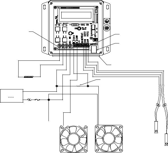
c)If you intend to use the controller to speed-control a fan rated for PWM control, connect the PWM speedcontrol wire as shown below through the rubber face plate, and connect to JP2-8. Be sure to consult the fan manufacturer for further details on the appropriate PWM frequency to use with the fan, minimum duty cycle required for the fan blade to spin, etc.
24
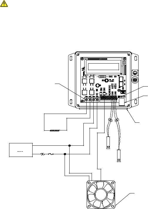
If the fan only has two or three wires, it is likely not rated for PWM fan-speed control. If the fan is not rated for PWM fan-speed control it should not be used in this configuration. Using PWM fan-speed control with a fan that is not rated for it can damage the fan.
The default configuration for JP2-8 is to serve as ALARM1 output. The controller will need to be software programmed (described in Section 4) for fan speed control rather than serving as ALARM1. ALARM2 may be configured to sense the temperature from the Primary Sensor or the Secondary Sensor as required.
JP7 |
|
|
|
|
|
|
|
|
|
|
|
|
|
|
|
|
PIN 1 |
|
|
|
|
|
|
|
|
|
|
|
|
|
|
|
|
|
JP7 |
1 |
2 |
3 |
4 |
JP2 |
10 |
9 |
8 |
7 |
6 |
5 |
4 |
3 |
2 |
1 |
to JP7-1 |
|
|
|
|
|
|
|
|
|
|
|
|
|
|
|
|
|
to JP7-2 |
|
|
|
|
|
|
|
|
|
|
|
|
|
|
|
TE DEVICE |
|
|
|
|
|
|
|
|
|
|
|
|
|
|
|
|
(+) |
(-) |
|
|
|
|
|
|
|
|
|
|
|
|
|
|
|
DC |
(-) |
|
to JP7-3 |
|
|
|
|
|
|
|
|
POWER SUPPLY |
|
|
|
OPTIONAL |
CONTROL |
12 V, 36 V, 20 A maximum |
|
|
to JP7-4 |
SECONDARY |
SENSOR |
(+) |
|
SENSOR |
JP2-1 (+) and |
||
|
|
||||
|
OPTIONAL FUSE |
|
JP2-4 (+) and |
JP2-2 (-) |
|
|
|
|
|||
|
|
THERMOSTAT AND OTHER |
|
JP2-3 (-) |
|
|
|
PROTECTIVE DEVICES |
|
|
|
|
|
(CUSTOMER SUPPLIED) |
|
|
|
|
|
|
|
to JP2-8 |
|
|
|
|
(+) (-) |
PWM |
|
NOTE: LID IS REMOVED TO SHOW WIRE CONNECTIONS
JP2
PIN 1
USB COMMUNICATION PORT
WIRES MUST PASS THROUGH GASKET HOLES
PWM FAN
Consult fan manufacturer for minimum allowable duty cylce before fan stops spinning and any other applicable requirements.
Connections, Fan Speed Control
(connections and components may vary depending on the fan being used)
25
d)ALARM1 or ALARM2 outputs could also be configured to power on or off devices such pumps or fans. Each alarm can manage up to 2 A of current. However, the total current comprised of the current passing through the alarm outputs plus the current passing through the TE device should not be allowed to exceed 20 A.
|
|
|
|
|
|
|
|
|
|
|
|
|
|
|
NOTE: LID IS REMOVED TO SHOW |
|
|
|
|
|
|
|
|
|
|
|
|
|
|
|
WIRE CONNECTIONS |
|
|
JP7 |
|
|
|
|
|
|
|
|
|
|
|
JP2 |
|
|
PIN 1 |
|
|
|
|
|
|
|
|
|
|
|
|||
|
|
|
|
|
|
|
|
|
|
|
|
PIN 1 |
|||
|
|
|
|
|
|
|
|
|
|
|
|
|
|
|
|
|
|
|
|
|
|
|
|
|
|
|
|
|
|
|
USB COMMUNICATION PORT |
|
|
|
JP7 |
1 |
2 |
3 |
4 JP2 |
10 |
9 |
8 |
7 |
6 |
5 |
4 3 2 1 |
|
|
to JP7-1 |
|
|
|
|
|
|
|
|
|
|
|
|
|
|
|
|
|
to JP7-2 |
|
|
|
|
|
|
|
|
|
|
|
WIRES MUST PASS THROUGH |
|
|
|
|
|
|
|
|
|
|
|
|
|
|
|
|
|
|
|
|
|
|
|
|
|
|
|
|
|
|
|
GASKET HOLES |
|
|
TE DEVICE |
|
|
|
|
|
|
|
|
|
|
|
|
|
|
(+) |
(-) |
|
|
|
|
|
|
|
|
|
|
to JP2-10 |
SUGGESTED |
|
|
|
|
|
|
|
|
|
|
|
|
|
|
|
(ALARM2) |
|
|
|
|
|
|
|
|
|
|
|
|
|
|
|
|
VOLTAGE DROPPING |
|
|
|
|
|
|
|
|
|
|
|
|
|
|
|
RESISTOR FOR ALTERNATIVE |
DC |
|
(-) |
to JP7-3 |
|
|
|
|
|
|
|
|
|
|
|
FAN SPEED CONTROL |
|
|
|
|
|
|
|
|
|
|
|
|
|
|
|
|
POWER SUPPLY |
|
|
|
|
|
|
|
|
|
|
|
|
|
|
|
≥12 V,≤36 V, 20 A maximum |
|
to JP7-4 |
|
|
|
|
|
|
|
|
|
|
|
||
|
|
(+) OPTIONAL FUSE |
|
|
|
|
|
|
|
|
|
|
|
|
|
|
|
|
THERMOSTAT AND OTHER |
|
|
|
|
|
|
|
|
|
|
|
|
|
|
|
PROTECTIVE DEVICES |
|
|
|
|
|
|
|
|
|
|
|
|
|
|
|
(CUSTOMER SUPPLIED) |
|
|
|
|
|
|
|
|
|
|
|
|
|
|
|
|
|
|
to JP2-8 |
|
|
|
|
|
|
|
|
|
|
|
|
|
|
|
(ALARM1) |
|
|
|
|
|
|
|
||
(+) |
(-) |
|
(+) (-) |
|
OPTIONAL
SECONDARY
SENSOR
JP2-4 (+) and
JP2-3(-)
CONTROL
SENSOR JP2-1 (+) and JP2-2 (-)
26

1.6Turn on power supply to the controller and power supply to the TE device if applicable and set controller and tuning parameters as necessary, described in Section 2 and Section 3 or in Section 4 using the software. The factory default is set to have output power to the TE device disabled when the controller is powered on for the first time. However, DO NOT ENABLE POWER OUTPUT TO THE TE DEVICE UNTIL THE APPROPRIATE CONTROL TEMPERATURE HAS BEEN SET AND THE TE DEVICE HAS BEEN PROPERLY CONFIGURED FOR USE WITH THE CONTROLLER. Once this is complete, only then should the output power be enabled.
NOTE: When not using a thermistor on the secondary sensor input, the
ALARM 2 TEMPS must be set to OFF and/or ALARM 2 FUNCTION must be set to KEEP OUTPUT ON.
sensor is attached. If one is not attached, the controller assumes there is a fault condition, and the controller default is set turn off output power in that event. Be sure to configure the controller settings accordingly.
The keypad could reach a normal operating temperature of 70 °C particularly if operating in a warm ambient temperature.
Do not mount the controller to a surface which is exposed to a source of heat, such as from electronics, machinery, or solar radiation.
Do not cover the controller with any object or otherwise restrict natural convection airflow around the controller. Doing so could cause the controller to overheat.
Do not mount the controller to an insulating surface. Doing so could cause the controller to overheat.
Do not operate the controller in such a manner as to cause the surface temperature of the case or internal temperature to exceed 70 °C. Otherwise the controller might be damaged and there might be a risk of fire as a result.
Do not allow the controller to be exposed to water (such as from dripping or leaking water lines or in which the controller is operating at or below the dew point temperature)
Do not allow metallic dust/shavings to enter into the controller box.
27

2.0 DISPLAY AND MENU OPTIONS
Note: this section applies only to the TC-720. Setup, programming, and communications with the TC-720 OEM controller can only be accomplished by using the computer software. Changes made to the controller using the keypad are always stored in the EEPROM regardless of EEPROM WRITE ENABLE setting.
POWER UP
TE TECHNOLOGY
WWW.TETECH.COM
TE TECHNOLOGY
TC-720 REV x
T1=xx.xx°C |
BEGIN |
|
OUT= OFF T2= xx |
||
|
OUTPUT ENABLE |
|
OFF |
|
OUTPUT= OFF |
|
ON |
|
|
|
||
|
CONTINUES |
1 |
YES |
|
BELOW |
|
|
|
|
|
|
RUN PROGRAM |
|
YES |
|
NO |
YES |
|
NO |
|
|
||
SET TEMPERATURE |
INCREASE |
xx.xx°C |
DECREASE |
PROPORTIONAL BW |
INCREASE |
DECREASE |
|
x.xx°C |
|
INTEGRAL GAIN |
INCREASE |
x.xx |
DECREASE |
DERIVATIVE GAIN |
INCREASE |
x.xx |
DECREASE |
ALARM 1 TEMPS
HIGH xxx LOW xxx
ALARM 1 TEMPS
HIGH xxx LOW xxx
ALARM 1 FUNCTION
KEEP OUTPUT ON
ALARM 2 TEMPS
HIGH xxx LOW xxx
ALARM 2 TEMPS
HIGH xxx LOW xxx
ALARM 2 FUNCTION
KEEP OUTPUT ON
ALARM LATCHES
NO LATCHES
CONTINUES ON
NEXT PAGE
INCREASE
DECREASE
OFF
INCREASE
DECREASE
OFF
OFF
ON
INCREASE
DECREASE
OFF
INCREASE
DECREASE
OFF
OFF
ON
NO LATCHES
ALARM 1 LATCH ALARM 2 LATCH ALARM 1&2 LATCH
28
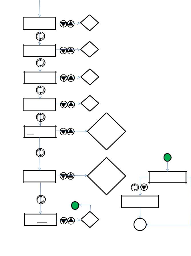
FROM PREVIOUS
PAGE
TEMP1 OFFSET x.xx°C
TEMP2 OFFSET x.xx°C
CONTROL RANGE HIGH xxx LOW xxx
CONTROL RANGE HIGH xxx LOW xxx
SENSOR 1 TYPE 15K-1
SENSOR 2 TYPE 15K-1
INCREASE
DECREASE
INCREASE
DECREASE
INCREASE
DECREASE
INCREASE
DECREASE
15K-1
10K-2
10K-1
5K-1 USER DEF 230K-1 50K-1
15K-1
10K-2
10K-1
5K-1 USER DEF 230K-1 50K-1
2 |
OK |
|
LOAD DEFAULTS |
OK |
|
OK |
CANCEL |
CANCEL |
2
HOLD MENU AND DOWN
BUTTONS FOR 3 SEC.
NO REPROGRAMMED TO ACTION FACTORY DEFAULTS
START
29

1
BEGIN |
T1= xx.x |
0% |
|
EXIT |
START |
||
|
T1= xx.xx |
x% |
Sn= xx.xx |
xx |
|
|
|
|
T1= xx.x |
x% |
|
|
END |
RESUME |
T1= xx.x |
|
R/S PROGRAM |
|
OUT= 0%/OFF# |
T2= xx/RS OFF* |
COMPLETE |
|
To exit the ramp/soak program:
OUTPUT ENABLE
OUTPUT= ON
1 |
YES |
To restart the |
|
|
ramp/soak program: |
RUN PROGRAM |
YES |
|
NO |
YES |
NO |
|
||
BEGIN |
NO Exits the ramp/soak |
|
program completely. |
||
|
Be sure that OUTPUT ENABLE has been set to ON; otherwise, the ramp/soak program will run but the percent output power will remain a 0%.
* Controller alternately displays “T2= xx” and “RS OFF” if a secondary sensor is connected. If a secondary sensor is not connected, “RS OFF” is displayed constantly.
# Controller alternately displays “OUT= OFF” and “OUT= 0%” if ENABLE OUTPUT was set to OFF prior to running the ramp/soak program. If the ENABLE OUTPUT was set to ON prior to running the ramp/soak program, “OUT= 0%” is displayed constantly.
30
Loading...