

Page 1

TECHNOLOGY, INC.
Operation Manual
For
Model TC-24-25
Thermoelectric Module
Temperature Controller
June 13 , 2006
Drawing #3458 Rev. G
TE
15 90 K ea n e D ri v e Ph o n e : ( 2 3 1 ) 9 2 9 - 3 9 6 6
Tr a v er se C i t y , M I 4 9 6 8 6- 82 57 Fa x: ( 2 3 1 ) 9 2 9 - 4 1 6 3
ht t p : / / w w w .t et ec h . c o m e- ma il : c o o l @ t e t e c h . c o m
Page 2

Table of Contents
Features.......................................................................................................................................................... 3
General Description ....................................................................................................................................... 4
Technical Description.................................................................................................................................... 4
Set-Up Instructions ........................................................................................................................................ 6
1.0 Setup ...............................................................................................................................................................................6
2.0 Configure ........................................................................................................................................................................7
3.0 Tuning.............................................................................................................................................................................9
4.0 Calibration ....................................................................................................................................................................10
5.0 Controller Operation .....................................................................................................................................................10
6.0 Custom Software...........................................................................................................................................................11
Block Diagram............................................................................................................................................. 12
Controller Wiring Diagram ......................................................................................................................... 13
Expansion Connector Wiring Diagram ....................................................................................................... 14
Mechanical Package Drawing ..................................................................................................................... 15
APPENDIX A RS-485 Cable Termination Requirements .......................................................................... 16
APPENDIX B Multiple Controller Wiring Diagram ................................................................................. 17
APPENDIX C Communications Port Address Assignments ...................................................................... 18
APPENDIX D RS-485 Troubleshooting Guide .......................................................................................... 19
APPENDIX E PID Tuning .......................................................................................................................... 20
APPENDIX F Serial Communications........................................................................................................ 22
APPENDIX G Thermistor Styles for TC-24-25.......................................................................................... 34
Notice: Improper tuning of this temperature controller (or any temperature controller) can lead to excessive thermal cycling
and/or overheating of the thermoelectric device, either of which are known to reduce the lifetime of any thermoelectric device.
Care should be taken to prevent the temperature of the thermoelectric device from going beyond the range specified by the
device manufacturer. Care should also be taken so that any thermal cycling of the thermoelectric device is a result of changes
in the controller’s set-point temperature and not instability at a given set point due to improper selection of the tuning variables.
In no event shall TE Technology, Inc. be liable for any damages whatsoever (including without limitation, damage for loss of
business profits, business interruption, loss of business information, or any other pecuniary loss) arising out of the use or
inability to use this TE Technology, Inc. product, even if TE Technology, Inc. has been advised of the possibility of such
damages.
2
Page 3

Features
● Input voltage from (12 to 28) VDC
● Self-contained, (0.1 to 25) A current rating
● computer programmable via RS-485 communications port
● Bi-directional, solid state H-bridge operation for heating and cooling applications
● Control temperature of –20 °C to +100 °C using MP-2379 thermistor (supplied with controller)
● Proportional (P), Integral (I), and Derivative (D) control that can be selected as P, PI, PD, or PID; or
Deadband (on/off) with an adjustable hysteresis
● Temperature resolution of 0.1 °C or 0.1 °F
● Control stability of up to ±0.1 °C or ±0.1 °F (when controlling a cold plate)
● Pulse-width modulation of output:
● Selectable modulation frequency of 675 Hz or 2700 Hz
● Controls up to 680 W
● 1500 VAC isolated RS-485 communications interface
● Set temperature selectable:
● computer set with controller stand alone operation
● Remote user set temperature using a potentiometer
● 0 mA to 20 mA current loop
● 0 VDC to 5 VDC adjustable range
● Differential temperature control
● No computer programming experience required to use the communications software program
(Supplied software is compatible with Windows 95/98/XP/NT)
● Command set is provided so programmers may create their own software interface or embedded
controller applications
● Versatile alarm system:
● Hardware output 5 VDC at 25 mA
● Alarm cancel is selectable via computer-software communication or remote contacts
● Second sensor also configurable as a heat-sink over-temperature shut-down
● Non-volatile memory retention of parameters (1,000,000 write cycles maximum; see command #31
in Appendix C for further details.)
● Operating temperature range of 0 °C to 65 °C
● Storage temperature range of -55 °C to +105 °C
3
Page 4

General Description
The TC-24-25 is a bi-directional control for independent thermoelectric modules or in conjunction with
auxiliary or supplemental resistive heaters for both cooling and heating applications. The "H" bridge
configuration of the solid state MOSFET output devices allows for the bi-directional flow of current
through the thermoelectric modules. Highly efficient N-channel output devices are used for this control
mode.
This controller is programmable via an RS485 communication port for direct interface or via an RS485
to RS232 converter which can then be connected to the serial communications port of a computer. The
RS485 communications interface has 1500 VAC isolation from all other electronic circuitry minimizing
interference from noise or errant signals caused by common ground loops. The easily accessible
communications link permits a variety of operational mode configurations. Field selectable parameters
or data acquisition in a half-duplex mode can be performed. This controller will accept up to 32
addressable interfaces, over a maximum of 4,000 feet of communications cable.
Once the desired set parameters are established, the TC-24-25 can be disconnected from the computer,
and it becomes a unique, stand-alone controller. All parameter settings are retained in non-volatile
memory.
The user friendly, communications software requires no prior programming experience to establish
operation. A command set is provided for qualified personnel to program a software interface or use as
an embedded control.
Mechanically, the control printed circuit board is mounted to a metal bracket that is suitable for either
horizontal or vertical orientation. Input and output connections are accessible via screw type terminal
strips and fast-on terminals.
Technical Description
The TC-24-25 is capable of operating from an input supply voltage of (12 to 28) VDC, common to many
available thermoelectric coolers. The self-contained MOSFET output devices deliver load currents from
(0.1 to 25) A. (NOTE: consult appropriate installation instructions for power supply and heat sinking
requirements for high current operation). This unit will control total load power up to 680 W with a
finite temperature resolution of 0.1 °C or 0.1 °F.
The output signal to the thermoelectric module is pulse-width modulated and can be set for either 675 Hz
or 2700 Hz operation. Pulse-width modulation (PWM) averages the amount of energy provided to the
module and reduces the extreme temperature excursions that are experienced with a thermostatic control
system. This tends to extend the life and reliability of the thermoelectric devices. The PWM control
scheme affords control accuracy to within ±0.1 °C or ±0.1 °F at the control sensor.
The controller tuning structure allows designation of a variety of control features:
1) The Computer Set Value provides for manual control of the output, from 0% to ±100% of load power.
2) Proportional bandwidth (P) in degrees, Integral reset (1) in repeats per minute, and the Derivative rate
(D) in minutes may be configured for P, PI, PD, or PID control.
4
Page 5

3) Deadband control (on/off) with an adjustable hysteresis may also be selected. However, this control
mode is not generally recommended.
4) Differential temperature control is provided when two input sensing thermistors are used. The unit
will control the differential between Input 2 (reference temperature) and Input 1 (actual system
temperature).
A control temperature range of –20 °C to +100 °C is standard when using TE Technology’s standard
thermistor sensor probe for the primary set temperature. Additional external set temperature input types
may be selected. As mentioned above, a second thermistor can be used for differential control (or it
could be used for alarm condition sensing). In addition, the controller could use a remote set temperature
potentiometer, a (0 to 5) VDC signal, or a (0 to 20) mA current loop. These secondary inputs are used to
define and “map” the secondary input to an adjustable temperature range in order to remotely control the
set temperature. All temperatures may be consistently displayed in °C or °F.
Two types of control output modes may be selected. This determines the direction of the current flow
through the thermoelectric module during the heat cycle. This current flow may be from wire-point
WP1+ to wire-point WP2-. Alternatively, this current flow may be reversed from WP2+ to WP1- as
selected in the configuration menu.
Several alarm settings may be selected, some of which provide a 5 VDC output, rated for 25 mA of
current for alarm signaling. The settings can be selected for no alarm function, tracking alarm, and
fixed-value alarm. Alarm set temperature values are entered in the setup menu. The computercontrolled selection is available for additional embedded controller input/output options. The alarm
setup menu also provides for selection of an alarm latching condition. The alarm sensor may be either
the control temperature sensor or a secondary thermistor sensor.
The various alarms have the ability to determine the status of the output power to the thermoelectric
module or auxiliary heater. Power may be maintained during an alarm condition or the main power may
be shut down.
5
Page 6

Set-Up Instructions
1.0 Setup
NOTE: the maximum allowable ambient temperature for the controller is 65 °C. Furthermore, the
maximum allowable temperature of the controller base (underneath the transistor-mounting area) is 80
°C.
1.1 Initial settings for the controller should be made using the supplied computer software. Make sure
the computer is off and the controller is un-powered. Connect the RS-485 Communications Port
from the controller to the RS-485 input on the computer or to an RS-232 to RS-485 converter. If a
converter is used, connect the RS-232 port on the converter to an available RS-232 port (serial
communications port) on the computer. See Appendix A “RS-485 Cable Termination
Requirements” before removing any of the resistors on the JP1 terminal strip. See Appendix B
“Multiple Controller Wiring Diagram” for wiring information. Contact TE Technology if
additional information is required on the RS-232 to RS-485 converter that is supplied with the TC24-25.
1.2 Attach the thermistor to the control location. Generally, this is the cold side of the cooler rather than
the part itself that is to be cooled/heated. This provides better control stability. As much wire
length of the thermistor should be thermally connected to the cold side as possible so that the
thermistor and its wire leads are as equivalent in temperature as possible. This can be accomplished
by using aluminum tape placed over the wire leads and adhered to the cold side of the cooler. This
will help eliminate errors resulting from heat conducting along the wire leads and affecting the
sensor reading.
The standard thermistor supplied with the TC-24-25 is the MP-2379. Appendix G “Thermistor
Styles for TC-24-25” shows dimensional data on the MP-2379 and other thermistor styles readily
available as well as temperature-resistance data. If you are using the MP-2379, it is recommended
that use thermal grease (such as TE Technology’s thermal grease, TP-1) between the thermistor and
the surface to which it is being mounted.
If you want to use thermistors that have different resistance-temperature curves than the standard
thermistor, it can be done as long as the operating resistance range is within that of the standard
thermistor. The thermistor should be a negative temperature coefficient device. Because the
temperature controller is really measuring the thermistor’s resistance and converting this to a
temperature, the temperature controller will be fooled into thinking that the thermistor is at a
different temperature than it really is, and the Set-Temperature will be skewed accordingly. A loss
of resolution and control stability may occur as a result. The user assumes all risks associated with
making any substitutions and TE Technology assumes no liability whatsoever for the operation of
the controller when a non-standard thermistor is used.
1.3 Connect the appropriate DC power (12* to 28 volts) to the controller between WP3+ and WP4- and
the thermoelectric module between WP1 and WP2 in accordance with the “Controller Wiring
Diagram.”
6
Page 7

NOTE: Generally, there is approximately a 0.5 to 1.3 V drop from the power supply to the
thermoelectric modules. You may wish to adjust the power supply accordingly to ensure full power
is delivered to the cooler when needed, subject to the 28 V limit.
*NOTE: For operation below 15 V, move the jumper on JP4 so that it connects both pins together.
The will allow proper operation down to 12 V. (See “Controller Wiring Diagram” for JP4 location.)
1.4 Turn power on to both the computer and power supply (which in turn powers up the controller).
The on-board green LED will flash at a steady rate to indicate that the controller is energized
correctly.
1.5 Insert the TC-24-25 software disk into the computer floppy-disk drive. To run the software from the
floppy disk, select START, RUN from your Windows Desktop and then enter A:\TC-24-25.exe.
This will load the software into your computer’s RAM. Alternatively, copy the TC-24-25.exe file to
your hard-disk drive and run the program from there.
1.6 The Main Menu screen will appear on your computer monitor. All selections are made from this
screen. In the PC COMMUNICATIONS section, select the RS-232 port (1 through 4) to which the
controller is connected by using the COMM PORT menu key. Assign a two-digit address code of
"00" to the controller for the initial set-up in the ADDRESS OF CONTROLLER TO ACCESS box.
The "00" code is the universal address which will communicate with all the controllers in a multiple
controller system. Refer to Appendix C “Communications Port Address Assignments” for
additional address code information and on how to install multiple controllers on a serial link. After
making these selections, click on the INITIALIZE button.
1.7 NOTE: If you receive an error message, please refer to Appendix D “RS-485 Troubleshooting
Guide.”
2.0 Configure
2.1 In the CONFIGURE section, the various selections are used to establish the custom operating
criteria for the controller. NOTE: To avoid damage to the thermoelectric cooler, confirm that OFF
is selected in the OUTPUT ON/OFF menu key, and then click the Send Box Values button prior to
proceeding!
2.2 First, select the PWM OUTPUT TIMEBASE menu key. Options for SLOW TIMEBASE 675Hz or
FAST TIMEBASE 2700Hz will appear. Select the option that is appropriate for you. Generally,
675 Hz will work fine, and it is the recommended default.
2.3 Next, click on the SET TEMP TYPE INPUT 2 menu key to reveal the options available.
COMPUTER SET VALUE is to be selected when using the software to set the desired control
temperature. The other selections, POTENTIOMETER SET, 0 TO 5vdc SET, and 0 TO 20ma SET,
are for external set temperature adjustments. Refer to the “Controller Wiring Diagram” and the
“TC-24-25 Block Diagram” for additional information. The controller default setting for these
options is the full range of the thermistor input sensor. The DIFF.SET=INP2+FIXED SET
establishes an actual set temperature that is the sum of the temperature sensed by the optional,
7
Page 8

secondary thermistor input sensor and the temperature entered as the FIXED SET TEMP value.
This allows the controller to maintain a constant temperature difference between the primary
thermistor temperature and the secondary thermistor.
2.4 Enter the SET TEMP HIGH RANGE and SET TEMP LOW RANGE values. These values are used
to linearly scale the temperature range that you are controlling within to the full range of the
external input. The set limit values must be within the temperature range that controller is capable
of controlling to.
For example, suppose you are using a (0 to 5) VDC external input to control the set temperature.
Suppose further that you enter -20 °C for the SET TEMP LOW RANGE and +100 °C for the SET
TEMP HIGH RANGE. This sets up a linear scale of 5 V per 120 °C, or 0.0417 V/°C. So, to
control to 10 °C, for example, you would set the external input voltage to 1.25 V.
2.5 Click the CONTROL TYPE menu key and select which type is appropriate for your application.
The DEADBAND CONTROL is an on/off control and PID CONTROL is a
proportional/integral/derivative control. COMPUTER CONTROL allows a constant, fixed
percentage of power to be applied to the thermoelectric cooler. Generally, DEADBAND
CONTROL should not be used unless care is taken to prevent the thermoelectric cooler from being
damage by excessive thermal cycling.
2.6 Clicking on the CONTROL MODE menu key permits the selection of either HEAT WP1+ AND
WP2- or HEAT WP2+ AND WP1-. These selections establish the polarity for the heating mode of
the thermoelectric cooler. This selection allows you to reverse the current flow in the thermoelectric
cooler without having to change the wiring.
NOTE: For TE Technology’s standard products, the TE+ (red) wire should be attached to WP2
and the TE- (black) wire should be attached to WP1 as shown in the “Controller Wiring Diagram.”
The CONTROL MODE should then be set to HEAT WP1+ and WP2-.
2.7 The ALARM TYPE menu key permits the selection of available alarm options. NO ALARM
PICKED indicates that no alarm parameters are desired. SET TRACKING ALARMS allows an
alarm to be set with respect to the set temperature. It will move accordingly with a change of the
temperature setting. This option can be used for a high alarm, low alarm, or both settings. FIXED
VALUE ALARMS permits the setting of a fixed, absolute temperature either above or below the set
point temperature or both. COMPUTER CONTROLLED ALARM is not an actual alarm, but
provides for user activation of the alarm relay via the computer software. The “Expansion
Connector Wiring Diagram” shows how customer-supplied LED’s can be installed to signal various
alarm conditions.
2.8 The POWER OUT SHUT DOWN IF ALARM menu key provides two selections. NO SHUT
DOWN IF ALARM will let the controller continue to control to the set temperature. MAIN OUT
SHUTDOWN IF ALARM shuts off power to the cooler when an alarm condition exists.
8
Page 9

2.9 Associated with the ALARM TYPE configuration are the HIGH ALARM SETTING, LOW
ALARM SETTING, and the ALARM DEADBAND settings. If an alarm type has been selected,
enter the desired high and low temperature values that you want to have trigger an alarm condition.
The ALARM DEADBAND option sets the hysteresis of the alarm values from 0.1 degrees to 100
degrees.
2.10 The ALARM LATCH menu key permits the selection of ALARM LATCH OFF or ALARM
LATCH ON. If ALARM LATCH OFF is selected, the controller will automatically reset if the
alarm condition self-corrects when the corresponding temperature returns back to the temperature
defined by the ALARM DEADBAND and alarm setting. If ALARM LATCH ON is selected, the
controller will maintain the alarm condition until it is manually cleared. When ALARM LATCH
ON is selected, and if an alarm condition exists, the alarm latch can be reset by clicking the SEND
LATCH CLEAR button.
2.11 The CHOOSE SENSOR FOR ALARM menu key allows for the selection of either the CONTROL
SENSOR thermistor or the INPUT 2 SENSOR thermistor for the alarm sensing. (Note: The
INPUT 2 SENSOR thermistor cannot be used if you are using a potentiometer or voltage/current
levels to control the set point.) The INPUT 2 SENSOR thermistor can be attached to the heat sink
in order to detect over-temperature conditions.
2.12 The CHOOSE DEG C OR DEG F UNITS menu key permits the selection of displaying °F or °C.
NOTE: The EEPROM WRITE ENABLE, located just below the CONFIGURE SECTION, can be
checked or unchecked depending on your requirements. See Appendix C, command #31, for more
information on EEPROM WRITE ENABLE.
2.13 Review all of the controller configuration selections. If all the configuration selections are correct
for the application, select the Send Box Values button to download these settings to the controller.
3.0 Tuning
3.1 You are now ready to tune the controller. All selections for this portion will occur in the TUNING
section of the controller software. The various constants required by the controller to optimize the
system performance are entered in this section.
3.2 The FIXED SET TEMP is the set temperature value entered in degrees. This temperature must be
within the range of the selected input sensor or the limits of low and high set ranges from the
controller configuration setup. Also, verify that the cooler is capable of safely operating at the
entered set temperature. This is particularly important if you are heating. While you can control to
+100 °C using the standard thermistor, many coolers are rated for at most 80 °C.
If you selected COMPUTER CONTROL in the CONTROL TYPE menu key under the
CONFIGURE section, the values that can be entered in the FIXED SET TEMP box range from
–12.0 to +12.0. This corresponds linearly to a fixed percentage of power output where –12.0 equals
–100% power and +12.0 equals +100% power.
9
Page 10

If the controller is configured as described in the “NOTE” in section 2.6, then -100% power will
correspond to full-power cooling.
3.3 PROPORTIONAL BANDWIDTH is the temperature band in which 0% to 100% power will be
applied to the cooler. The acceptable bandwidth values that may be entered are 1° to 100°. See
Appendix E “PID Tuning” for additional information on settings.
3.4 INTEGRAL GAIN is used to slowly change the output power until the difference between the
actual temperature and set temperature is zero. This value is expressed in repeats per minute, and
the acceptable values that may be entered are 0.01 to 10 repeats per minute.
3.5 DERIVATIVE GAIN senses the rate of rise or fall of the system temperature and adjusts the cycle
time of the controller to minimize overshoot or undershoot. This value is expressed in cycle rates
per minute, and the acceptable values that may be entered are 0.01 to 10 cycles per minute.
3.6 CONTROL DEADBAND is the temperature band where the controller is turned on and off by
either rising or falling temperatures where no heating or cooling takes place. This band is expressed
in degrees, and the acceptable values that may be entered are 0.1 to 100.
3.7 Review the tuning parameters for correctness and then click the Send Box Values button to
download these constants to the controller.
4.0 Calibration
4.1 The CALIBRATE section provides additional variables that can be used to fine-tune your system’s
operation. You may want to try controlling with the initial settings prior to entering values in this
section.
4.2 INPUT 1 OFFSET is a manual method of compensating for the sensor 1 temperature and actual
control temperature.
4.3 INPUT 2 OFFSET is a manual method for compensating for the sensor 2 temperature and actual
temperature.
4.4 HEAT SIDE MULTIPLIER is a 0.01 to 2.00 numerical multiplier that compensates for the non-
symmetrical response of the thermoelectric cooler between the heat and cool modes.
4.5 If you have entered values in the CALIBRATE box and they are desired settings, click the Send
Box Values button to download these constants to the controller.
5.0 Controller Operation
5.1 Initial set-up of the TC-24-25 controller is complete.
5.2 Select ON in the OUTPUT ON/OFF menu key located in the CONFIGURE section. Then click the
Send Box Values in the CONFIGURE section to turn the controller on.
10
Page 11

5.3 Click the SAMPLE button to monitor the CONTROL SENSOR’s temperature. This temperature is
indicated in the TEMP box. If you have an INPUT 2 SENSOR thermistor attached, its temperature
is indicated in the SECOND SENSOR box.
5.4 If all of the settings are satisfactory, you can turn off the computer and power supply, disconnect the
controller from the RS-232 port, and turn back on the power supply. The controller remembers its
last settings on EEPROM and will resume control based on that.
6.0 Custom Software
The controller does not specifically have to be used with the software that is provided. You could
also use commercial software such as LabVIEW from National Instruments. This might be useful if
you wanted to control a specific temperature profile over a particular amount of time. This is
accomplished by communicating through the RS-232 port of the computer using the command set
for the controller. The command set is given in Appendix F “Serial Communications.”
11
Page 12
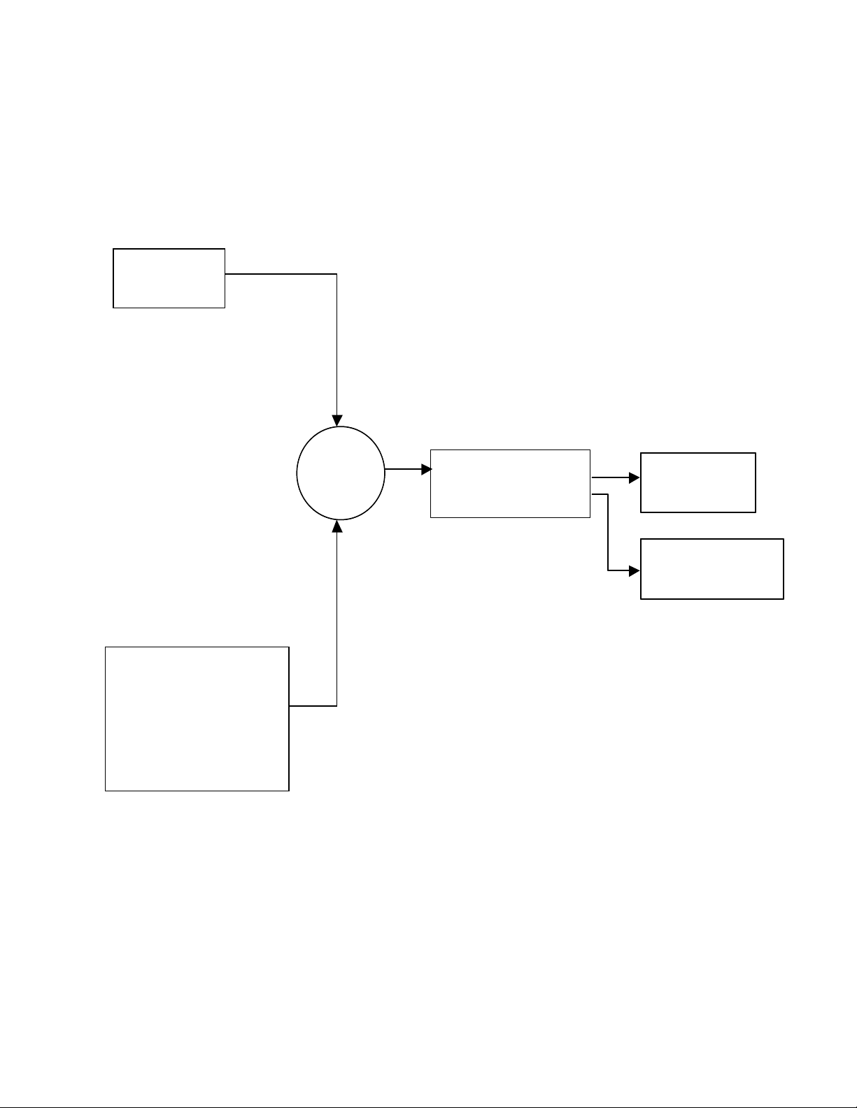
INPUT #1 S ENSOR
INPUT #1 S ENSOR
TEMPERATURE
TEMPERATURE
SENSOR
SENSOR
-20 °C TO 100 °C
-20 °C TO 100 °C
SUMMING
SUMMING
JUNCTION
JUNCTION
Block Diagram
CONTROL
CONTROL
PID
PID
PID W/ ALARM
PID W/ ALARM
DEADBAND
DEADBAND
DEADBAND W/ ALARM
DEADBAND W/ ALARM
OUTPUTS
H-BRIDGE
H-BRIDGE
1 TO 25 A PWM
1 TO 25 A PWM
675 OR 2700 Hz
675 OR 2700 Hz
INPUT #2 AUXILL ARY INPUT
INPUT #2 AUXILL ARY INPUT
10K OHM PO TENTIOME TER
10K OHM PO TENTIOME TER
0 TO 5 VDC*
0 TO 5 VDC*
4 to 20 mA DC**
4 to 20 mA DC**
OR
OR
0 TO 20 mA DC**
0 TO 20 mA DC**
PC SET VALUE
PC SET VALUE
DIFF SET = INPUT 2
DIF F SET = INPUT 2
*CONTROLLER INPUT IMPEDANCE 6.5K OHMS
*CONTROLLER INPUT IMPEDANCE 6.5K OHMS
**REQUIRES ADDITION OF EXTERNAL RES ISTOR
**REQUIRES ADDITION OF EXTERNAL RES ISTOR
REMOTE INDICA TOR
REMOTE INDICA TOR
RED/YELLOW/GREEN
RED/YELLOW/GREEN
LED’S
LED’S
12
Page 13
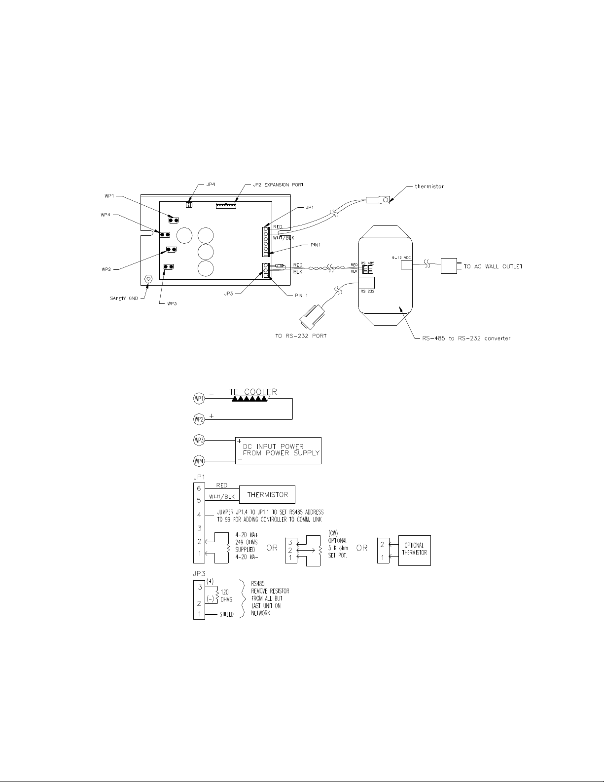
Controller Wiring Diagram
13
Page 14
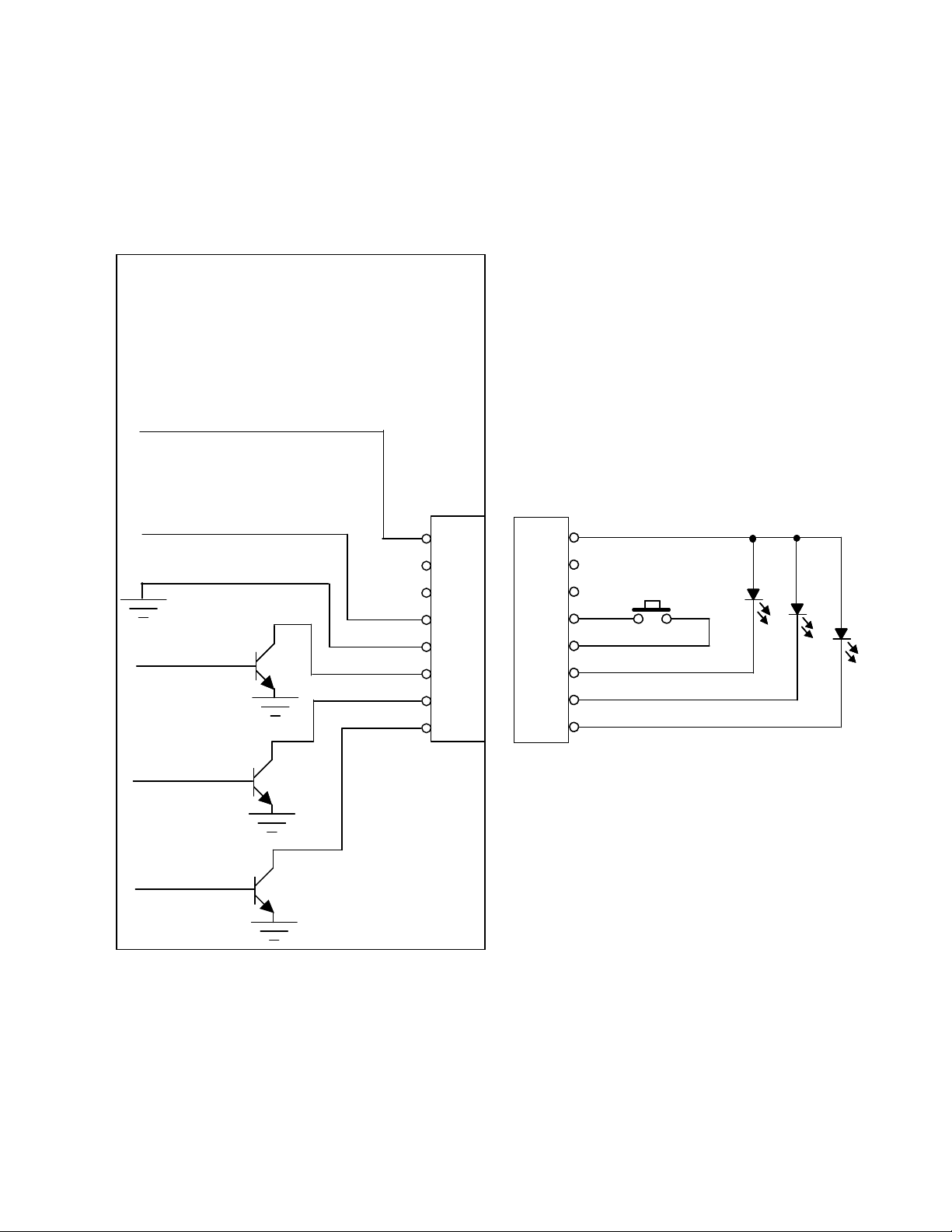
Expansion Connector Wiring Diagram
Note: The 25 mA current source is a true current source. Maximum compliance voltage is approximately
equal to the input voltage to the temperature controller. No external current limit resistors are needed for
the LED. The LED must be capable of being driven with a 25 mA continuous current.
Expansion Connector
Expansion Connector
Molex 22-23-2081
Molex 22-23-2081
25 mA Current Source
25 mA Current Source
Customer- supplied
Customer- supplied
JP2
Alarm Cancel
Alarm Cancel
Input Common
Input Common
High Alarm
High Alarm
JP2
8
8
7
7
6
6
5
5
4
4
3
3
2
2
1
1
Connector
Connector
8
8
7
7
6
6
5
5
4
4
3
3
2
2
1
1
Low Alarm
Low Alarm
No Alarm
No Alarm
14
Note: Pins 6 and 7 not functionally defined.
Note: Pins 6 and 7 not functionally defined.
Please do not connect.
Please do not connect.
Page 15
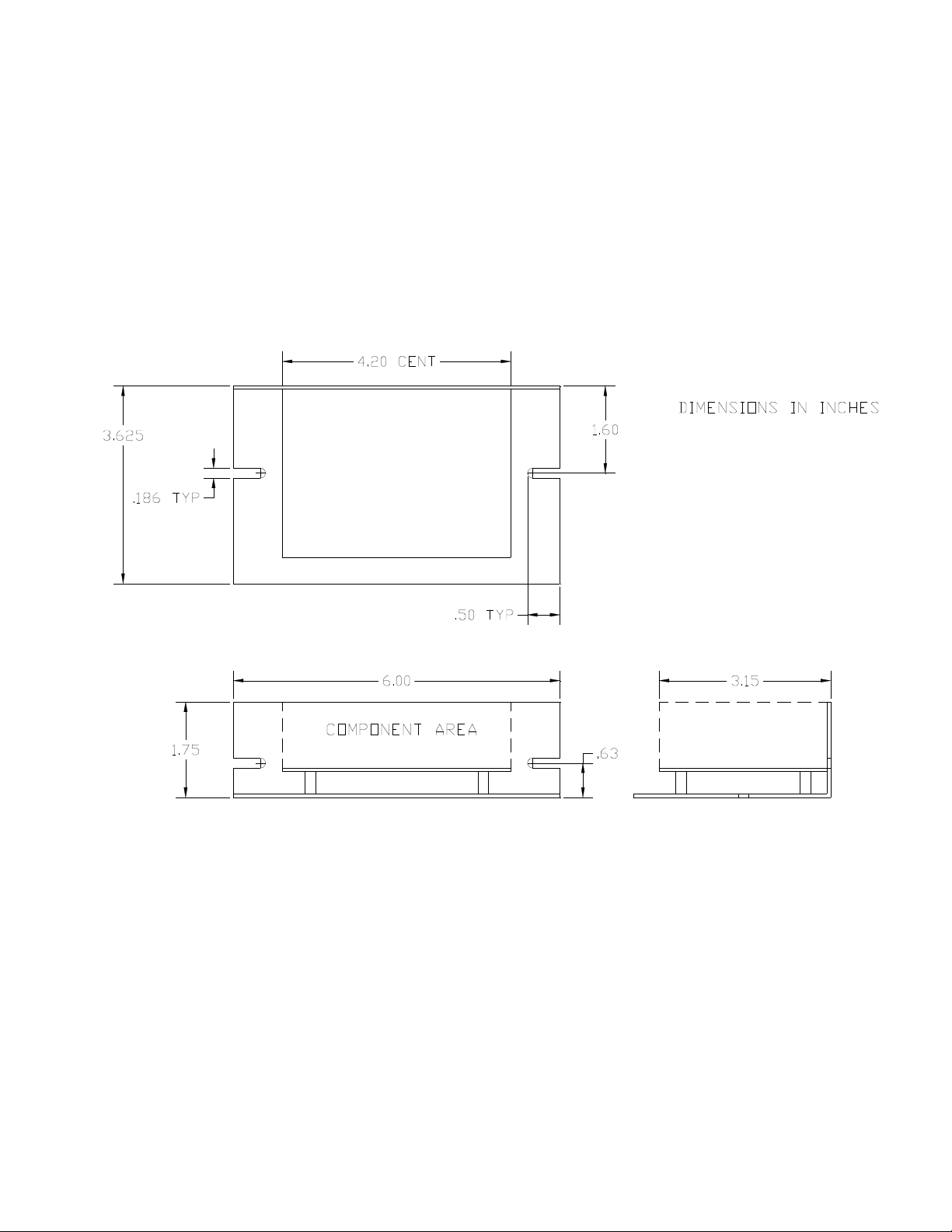
Mechanical Package Drawing
15
Page 16

APPENDIX A RS-485 Cable Termination Requirements
A twisted pair of wires for RS-485 applications may connect up to 32 ports for half-duplex data
transmission. An optional shield around the twisted pair helps reduce unwanted noise, and is connected
to ground at one end.
Proper termination of the cable is very important. If the cable is not correctly terminated with its
characteristic impedance, normally 120 ohms, distorted waveforms will result. Unwanted reflections
signals may occur which can distort or interrupt data transmission.
Cable terminating resistors are required at each physical end of the cables to prevent theses unwanted
reflections (Refer to Appendix B Multiple Controller Wiring Diagram). The typical differential output is
2 volts with two 120 ohm terminating resistors, causing 33mA of DC current in the cable when no data is
being sent. The preferred terminating resistor type is a metal film rated at ¼ watt.
This termination method permits connections up to 4,000 feet of RS-485 cable.
NOTE:
1) If an RS-232 to RS-485 converter is being used (other than the one supplied with the TC-24-25), please
check the converter manual to determine if a 120 ohm terminating resistor is included. The converter
supplied with the TC-24-25 has a 120 ohm resistor already installed within the converter. Also, each TC24-25 includes a 120 ohm terminating resistor. In multiple controller configurations, the resistor should
be removed from each controller except for the last controller in the line. Again, refer to Appendix B
Multiple Controller Wiring Diagram.
2) However, a string of TC-24-25 controllers may cause low signal levels from the RS-485 driver circuit
depending on the driver circuit being used, line length, wire diameter, number of controllers, etc. In this
case you may want to use a larger value (higher resistance) terminating resistor or remove it completely if
you are experiencing communication problems.
16
Page 17
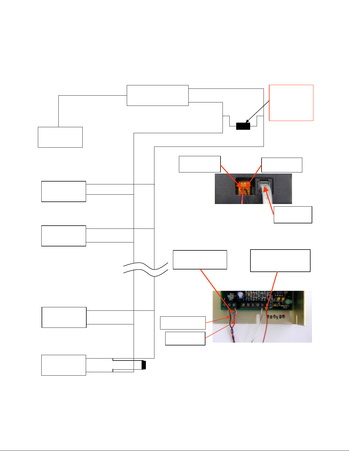
COMPUTERCOMPUTER
PIN OUTS PROVIDED FOR
APPENDIX B Multiple Controller Wiring Diagram
RS-485 PORT #1
(ORA NGE WAGO CONNECTOR)
RS-232 PORT
(RJ11 CONNECTOR)
RS-232 (COMM PORT)
PIN 1 – CTS
PIN 2 – RTS
PIN 3 – COM
PIN 4 – TXD
PIN 5 – RXD
PIN 6 – DSR
REFERENCE ONLY
RS-232 TO RS-485
RS-232 TO RS-485
CONVERTER
CONVERTER
+ PIN 3
– PIN 2
PIN 3 RS-485
(RED WIRE)
120 OHMS
PIN 2 RS-485
(BLACK WIRE)
If using the supplied
RS-2 32 to RS-485
converter, t h is 120
ohm resistor is already
installed with in th e
converter itself.
TC-24-25
TC-24-25
UNIT #1
UNIT #1
TC-24-25
TC-24-25
UNIT #2
UNIT #2
TC-24-25
TC-24-25
UNIT #30
UNIT #30
TC-24-25
TC-24-25
UNIT #31
UNIT #31
+
–
+
–
+
–
+ (red wire)
– (black wire)
RS-485 PORT #2
RS-485 PORT #3
RS-485 PORT #31
BLACK WIRE FROM
RS-485 TO JP3-2
RED WIRE FROM
RS-485 TO JP3-3
RS-485 PORT #32
120 OHMS
Picture of Converter
Terminating Resistor
from JP3-3 to JP3-2
Picture of TC-24-25
RJ11
RS-232 PORT
Thermistor wires to
JP1-5 and JP1-6
(Polarity not important)
17
Page 18

APPENDIX C Communications Port Address Assignments
The 00 Communications Port Address code is the universal address to which all controllers will respond.
Placing a jumper between pins JP1-4 and JP1-1 on the host controller will initiate a 99 Communications
Port Address code, when the controller is powered. This code is used to set-up newly added controller to
the serial link. This jumper should be removed upon completion of this set-up.
Additional Communications Port Address codes from 01 to 98 are used to identify individual controllers
of the serial link. The total numbers of controllers that make up the serial link is 32 ports.
The CONTROLLER COMM. ADDRESS in the CONFIGURE section is the address that is sent to the
controller and stored in non-volatile memory. This address must be unique to the controller.
The ADDRESS OF CONTROLLER TO ACCESS in the PC COMMUNICATIONS section indicates
which controller the software should monitor and send data.
00 is the address that communicates with all controllers. 99 is the address of a controller when it has a
jumper between pins JP1-4 and JP1-1 (address programmed in non-volatile memory on power-up). These
two addresses cannot be given to specific controllers as they are reserved.
Assigning A New Controller Address
If the controller is the only one hooked up to the computer, ensure the SELECT COMM PORT in the PC
COMMUNICATIONS section is indicating the comm port the controller is attached to. Enter 00 in the
ADDRESS OF CONTROLLER TO ACCESS. Check the Enable New Controller Address box. Click the
INITIALIZE button. In the CONFIGURE section, enter the new address in the CONTROLLER COMM.
ADDRESS box. Click the Send Box Values button.
You can verify the controller is functioning under the new address by entering the address in the
ADDRESS OF CONTROLLER TO ACCESS box under the PC COMMUNICATIONS section. Check
the Enable New Controller Address box. Click the INITIALIZE button. Then click the SAMPLE button.
A temperature readout should appear in the TEMP box.
Example: Adding a controller to a chain of controllers without pre-programming a specific address
in the non-volatile memory
If you have multiple controllers on an RS-485 chain and you want to add a new controller without preprogramming a unique address, there is a slightly different procedure. With the systems unpowered, add
the new controller to the chain and install a jumper between pins JP1-4 and JP1-1 on the controller you
are adding. Next, power up the systems. When the new controller is turned on, it recognizes there is a
jumper installed and changes its address to 99 in the non-volatile memory. Next, change the address to 99
in the ADDRESS OF CONTROLLER TO ACCESS box so you can communicate with this controller.
Then, change the CONTROLLER COMM. ADDRESS box to 07 and click the Send Box Values button.
This re-programs the non-volatile memory with an address of 07. Then, you can change the address to 07
and communicate with the controller again. Finally, you need to remove the jumper so it is not
reprogrammed with an address of 99 on the next power-up.
18
Page 19

APPENDIX D RS-485 Troubleshooting Guide
For troubleshooting always set the RS-485 port to 00, until correct communication is established.
You can perform a quick check of the comm. port (without having to initialize variables) by clicking the
“CommCheck” button in the PC COMMUNICATIONS section of the software screen. You should have
the controller connected to a comm. port and the controller powered up when performing the comm.
check. A “COMM ERROR!” message will show if there is no hookup. If the connection is good a
“COMM OKAY” message will quickly appear.
When you initialize, an error message my show up if there is any additional problems. The following
table offers possible solutions corresponding to a particular error:
Error Message Possible Cause Solution
Comm Port Timeout No power to TC-24-25 unit Apply power to TC-24-25, review
customer-hookup drawing for proper
hookup.
Comm Port Timeout RS-485 Address is wrong Set to 00 the universal address.
Comm Port Timeout Wrong Comm Port selected Check computer hardware setting and set to
the correct Comm Port.
Comm Port Timeout Comm Port is not connected to
converter or computer.
Comm Port Timeout Incorrect wiring of Comm Port
to the converter or computer.
Comm Port Timeout Converter is not connected to
TC-24-25.
Comm Port Timeout Incorrect wiring of the
converter to TC-24-25
Comm Port Open
Error
Note: See also Appendix F, Section III RS485 or RS232 Communications Parameters regarding the
insertion of a delay between sending characters if you are using your own software program.
No Comm Port available at this
port setting.
Check for correct connection of the
converter to the computer, review converter
specifications & computer for proper
hookup.
Check for correct wiring of the converter to
the computer, review converter
specifications & computer for proper
hookup.
Check for correct connection of the
converter to TC-24-25, review converter
specifications & TC-24-25 customer
drawing for proper hookup.
Check for correct wiring of the converter to
TC-24-25, review converter specifications
& TC-24-25 customer drawing for proper
hookup.
Check computer hardware setting and set to
the correct Comm Port.
19
Page 20

APPENDIX E PID Tuning
Tuning the TC-24-25 temperature controller involves three variables: (P)ROPORTIONAL
BANDWITH, (I)NTEGRAL GAIN, and (D)ERIVATE GAIN.
The control algorithm sums the three values of these terms to determine the output power.
P + I + D = > Power Applied
Most applications work satisfactorily with only the “P” and “I” values used.
Start the tuning process by setting the Integral and Derivative functions to zero. Then turn on the
controller.
PROPORTIONAL BANDWITH is defined as the temperature range around the set point where the
controller modulates (proportions) the output power. When the actual temperature deviates from the set
temperature, the “P” term of the control equation is increased until the power output reaches 100%.
Stated another way, the amount of temperature deviation required to increase the output to 100% is, by
definition, the proportional bandwidth. The programmable bandwidth range of the TC-24-25 is from 1°
to 100°. The units are shipped with a default setting of 20°.
Each thermal system has its own time constants determined by the thermal mass of the components and
the placement of the sensor relative to the load. When the “I” and “D” terms are set to zero, and the
bandwidth is too large, the temperature will never reach the set point. In this case the controller’s output
will approach zero as the temperature difference approaches zero, so the system will never get the
required power to actually reach the set point. On the other hand, if the bandwidth is too small and there
is any time lag between the cooling/heating element and the temperature sensor, the temperature will
initially overshoot the set point and then settle into a pattern of oscillation above and below the set point.
Assuming the controller is configured for your requirements, start the tuning process by applying power
with the default settings and observing the system’s response. If the system comes into the proportional
band and maintains a steady temperature near set point, without over shoot, the bandwidth setting is either
satisfactory or too large. Reduce the bandwidth setting until the system just begins to oscillate. At this
point, the bandwidth is too small. Note the bandwidth setting that just caused the system to oscillate, and
record the period of oscillation for use in determining the Integral Gain setting. To set the proportional
bandwidth, multiply the current bandwidth setting by 1.5 and use it as your new bandwidth setting. The
system should come into control and maintain a steady temperature near the set point.
INTEGRAL GAIN monitors the difference between the set point and the actual temperature. Its
function is to slowly change the output power until the difference between actual temperature and set
temperature is zero.
The function works by integrating the error signal at fixed intervals. The intervals are expressed in
repeats per minute. The acceptable range for the TC-24-25 is 0.01 to 10 repeats per minute. Start with a
setting determined by the following formula:
Integral Gain = 1/(2 x T) where “T” is the period of oscillation measured above. The period is expressed
in minutes.
20
Page 21

Example: The system’s period of oscillation with the appropriately set Proportional Bandwith was 75
seconds. Therefore, the suggested Integral Gain is
Integral Gain = 1/(2 x 1.25 minutes) = 0.4 repeats/minute.
For slower response but better stability, reduce the Integral Gain.
DERIVATE GAIN senses the rate of change of the temperature and allows the controller to anticipate
the power needed to compensate for rapid changes in system loading. This term is generally used only on
very sluggish systems or where very quick response is necessary. The acceptable range for the TC-24-25
is 0.1 to 10 cycles per minute.
To determine an appropriate derivate rate, use the following formula:
Derivate Gain = Integral Gain/10.
Continuing the above example, the Derivate Gain would be 0.04 cycles per minute.
NOTE: DERIVATIVE GAIN is difficult to apply and often causes more trouble than it is worth. If you
are not experienced in process control, you may be better off leaving the DERIVATIVE GAIN at zero.
21
Page 22

APPENDIX F Serial Communications
I. Definitions:
All numeric values are in hexadecimal format.
Use lowercase ASCII characters.
(stx) Start of text character (*) 2a hex.
(etx) End of text character (carriage return) or 0d hex.
(ack) Acknowledge character (^) 5e hex.
AA Address characters are ASCII characters from 0 through 9 or a through f.
00 is universal address of all controllers when using a chain of the RS-485 based
devices.
CC Command characters are ASCII characters from 0 through 9 or a through f.
DDDDDDDD Hex two’s-complement return or send value.
1d = 00000001
-1d=ffffffff
SS The 8-bit (modulo 256) checksum of characters sent to/from the controlling computer.
This is represented as 2 ASCII hex characters. The checksum calculation excludes the
characters (stx), SS, (etx). The TC-24-25 sums (in an 8-bit register) the ASCII values of
the characters sent to/from the controlling computer. Any overflow is truncated, leaving
the 8-bit (modulo 256) checksum. When the controller is receiving data, this number (as
represented by two hex characters) is compared to the two ASCII character hex checksum
sent by the controlling computer. The TC-24-25 will respond as shown below depending
on whether or not the checksums match. When the controlling computer is receiving data
the checksum sent by the controller can be used to make sure the data has not been
received with an error. Remember, when finding the ASCII value for a hex number (a, b,
c, d, e, and f) be sure to use lower case letters.
To write a command to a controller, the controlling computer must send the following ASCII characters:
(stx)AACCDDDDDDDDSS(etx)
If the temperature controller receives the command and the checksum is correct, the temperature
controller will respond by sending back the “send value” and the checksum of those eight ASCII
characters:
(stx)DDDDDDDDSS(ack)
To query a controller, there is no send value so the controlling computer only needs to send the following
ASCII characters:
(stx)AACCSS(etx)
If the temperature controller receives the query and the checksum is correct, the temperature controller
will respond by sending back a “return value” and the checksum of those eight ASCII characters:
(stx)DDDDDDDDSS(ack)
22
Page 23

If the checksum for a command or query is not correct the temperature controller will respond with eight
upper case X’s and then c0, which is the checksum of these eight X’s:
(stx)XXXXXXXXc0(ack)
Remember, AA = 00 is the universal address, and all controllers will respond (be careful!). If JP1-6 is
jumped to JP1-3 when powered, then the controller’s address will be 63 hex (used to setup newly added
controller to the serial link). If the address is not correct or not as listed immediately above then the
controller will not respond to any requests.
II. Examples:
Set the controller at address 01 to control via a computer programmable set point.
1. The controller address, AA, is by definition 01.
2. The control command, CC, for “INPUT2 DEFINE” is 29 hex.
3. A data value of “0” selects a computer communicated set value, so the eight-character send
value DDDDDDDD is 00000000.
4. Compute the checksum (SS) by adding the ASCII values of the following characters: 0, 1, 2,
9, 0, 0, 0, 0, 0, 0, 0, and 0:
ASCII Character:
Hex Value:
0 30 hex
1 31 hex
2 32 hex
9 39 hex
0 30 hex
0 30 hex
0 30 hex
0 30 hex
0 30 hex
0 30 hex
0 30 hex
0
30 hex
Sum 024c hex
The 8-bit checksum is the 8 least significant binary bits of the sum, represented as
4c in hex.
5. Combining all of these characters in one string we send: (stx)0129000000004c(etx).
6. If the temperature controller receives the command and the checksum is correct, it will send
back: (stx)0000000080(ack). If the checksum is not correct the temperature controller will
send back: (stx)XXXXXXXXc0(ack).
23
Page 24

Send the set temperature of 100.0 °F to the controller at address 01.
1. The controller address, AA, is by definition 01.
2. The control command, CC, for “FIXED DESIRED CONTROL SETTING” is 1c.
3. Multiply the desired set-point temperature by 10 (100.0 converts 1000d).
4. Convert 1000d to hex (03e8h) and add on leading zeros to make the eight-character
send value DDDDDDDD (000003e8).
5. Compute the checksum (SS) by adding the ASCII values of the following characters:
0, 1, 1, c, 0, 0, 0, 0, 0, 3, e, and 8:
ASCII Character:
Hex Value:
0 30 hex
1 31 hex
1
31 hex
c 63 hex
0 30 hex
0 30 hex
0 30 hex
0 30 hex
0 30 hex
3
33 hex
e 65 hex
8
38 hex
Sum 02b5 hex
The 8-bit checksum is the 8 least significant binary bits of the sum, represented as b5 in
hex.
6. Combining all of these characters in one string we send: (stx)011c000003e8b5(etx).
7. If the temperature controller receives the command and the checksum is correct, it will
send back: (stx)000003e8c0(ack). If the checksum is not correct the temperature
controller will send back: (stx)XXXXXXXXc0(ack).
Read the actual temperature of the control thermistor (INPUT1) from the controller at address 01.
1. Let’s assume the actual temperature is 25.0 °C, and the working units have been
defined as °C. This means that the controller will return a value in °C.
2. The controller address, AA, is by definition 01.
3. The control command, CC, for “INPUT1” is 01 hex.
4. There is no send value, so we can just calculate the checksum (SS) by adding the
ASCII values of the following characters: 0, 1, 0, and 1:
ASCII Character: Hex Value:
0 30 hex
1 31 hex
0 30 hex
1
31 hex
Sum 00c2 hex
The 8-bit checksum is the 8 least significant binary bits of the sum, represented as
c2 in hex.
5. Combining all of these characters in one string we send: (stx)0101c2(etx).
6. If the temperature controller receives the command and the checksum is correct, it will
send back: (stx)000000fae7(ack). The e7 at the end of the string is the checksum of
“000000fa”. The value ”000000fa” hex converts to 250 in decimal. This number,
when divided by 10 is 25.0, is the temperature in °C. As in the other examples, if the
24
Page 25

checksum from the query were not correct the temperature controller would send back:
(stx)XXXXXXXXc0(ack).
III. RS485 or RS232 Communications Parameters
A. Baud Rate 9600
B. No Parity
C. 1 Start Bit 1 Stop Bit
NOTE if you are using communications software different from the one supplied with the
controller: The demands of temperature control require a relatively large portion of the
processing power of the onboard microcontroller. It is possible for a host computer to send data
too quickly for the controller to receive and update. TE Technology recommends adding a delay
between each character sent to allow the controller sufficient time to process the information. One
millisecond might be a good delay time to use initially, but the exact time will vary depending on
the host computer’s hardware and the particular demands on the controller at the moment.
IV. Commands
1. INPUT1 (controlled input value)
Write Command: NA
Read Command: 01 hex
Interpret: Divide returned fixed-point temperature value by 10.0 and convert
to degrees F/C decimal value.
Example:
Receive 100.0 °F temp from unit (sensor type = 1).
Send: *01010000000042(etx)
Receive *000003e8c0^
Convert hex 000003e8 returned to decimal = (1000)
Divide by 10.0 = (100.0°F)
2. DESIRED CONTROL VALUE (set value)
Write Command: NA
Read Command: 03 hex
Interpret: This command returns the set value determined by Input2 or as a
fixed value set by communications (see #1 above for interpretation).
3. POWER OUTPUT
Write Command: NA
Read Command: 04 hex
Interpret: -255 represents –100% output.
0 returned is 0% output.
255 represent 100% output.
4. ALARM STATUS
Write Command: NA
Read Command: 05 hex
Interpret: 0 returned means no alarms.
Bit 0 = 1 means HIGH ALARM.
25
Page 26

Bit 1 = 1 means LOW ALARM.
Bit 2 = 1 means COMPUTER CONTROLLED ALARM.
5. INPUT 2
Write Command: NA
Read Command: 06 hex
Interpret: Input 2 reading as a thermistor temperature sensor.
6. ALARM TYPE
Write Command: 28 hex
Read Command: 41 hex
Interpret: 0 sent or returned means no alarms.
1 sent or returned means Tracking Alarm Mode.
2 sent or returned means Fixed Alarm Mode.
3 sent or returned means Computer Controlled Alarm Mode (see
write command 2f hex).
7. INPUT2 DEFINE (the desired control temperature or “set temp” input definition)
Write Command: 29 hex
Read Command: 42 hex
Interpret: This function tells the controller how the set-point temperature will
be communicated.
0 sent or returned means computer communicated set value.
1 sent or returned means Potentiometer Input.
2 sent or returned means 0 to 5 V Input.
3 sent or returned means 0 to 20 mA Input.
4 sent or returned means “Differential set”: Desired Control Value
= Temp2 + Computer Set.
Range of values settable via commands 20 hex & 21 hex (HIGH
ALARM SETTING and LOW ALARM SETTING).
8. RS485 ADDRESS
Write Command: 2a hex
Read Command: 43 hex
Interpret: The address of a controller for use with multiple controllers on the
link. This must be a 2-digit hex value. 00 is the universal address
and 63h is reserved for when JP1-3 is jumpered to JP1-6 (installing
a new controller the link).
9. CONTROL TYPE
Write Command: 2b hex
Read Command: 44 hex
Interpret: 0 is deadband control.
1 is PID control.
2 is computer control. With this setting, the output power sent to the
cooler is determined by sending a write command (0x1c) to
INPUT1. The range of values then becomes -120 to +120, which
corresponds to -100% output power to +100% output power.
26
Page 27

10. CONTROL OUTPUT POLARITY
Write Command: 2c hex
Read Command: 45 hex
Interpret: 0 is HEAT WP1+ and WP2-.
1 is HEAT WP2+ and WP1-.
11. POWER ON/OFF
Write Command: 2d hex
Read Command: 46 hex
Interpret: 0 is off
1 is on.
12. OUTPUT SHUTDOWN IF ALARM
Write Command: 2e hex
Read Command: 47 hex
Interpret: 0 is no shutdown upon alarming.
1 is to shutdown main output drive upon alarming.
13. FIXED DESIRED CONTROL SETTING
Write Command: 1c hex
Read Command: 50 hex
Interpret: When writing, multiply the desired control temperature by 10 and
convert to hex. This becomes the “send value”
When reading, convert the “return value” to decimal and divide by
10.0 to convert to ° F/°C.
14. PROPORTIONAL BANDWIDTH
Write Command: 1d hex
Read Command: 51 hex
Interpret: Fixed-point temperature bandwidth in °F/°C.
Multiply desired bandwidth by 10.
1 °F/°C bandwidth would be 10 decimal.
100 °F/°C bandwidth would be 1000.
15. INTEGRAL GAIN
Write Command: 1e hex
Read Command: 52 hex
Interpret: Fixed-point gain in Repeats/min.
Multiply desired integral gain by 100.
0.01 rep/min would be 1 decimal.
1.00 rep/min would be 100 decimal.
16. DERIVATIVE GAIN
Write Command: 1f hex
Read Command: 53 hex
27
Page 28

Interpret: Fixed-point gain in minutes.
Multiply desired derivative gain by 100.
0.01 min would be 1 decimal.
1.00 min would be 100 decimal.
17. LOW EXTERNAL SET RANGE
Write Command: 20 hex
Read Command: 54 hex
Interpret: Value mapped to zero voltage of Input2.
18. HIGH EXTERNAL SET RANGE
Write Command: 21 hex
Read Command: 55 hex
Interpret: Value mapped to 5 volt or maximum voltage of Input2.
19. ALARM DEADBAND
Write Command: 22 hex
Read Command: 56 hex
Interpret: Temperature Input1 must move to toggle
alarm output.
20. HIGH ALARM SETTING
Write Command: 23 hex
Read Command: 57 hex
Interpret: Temperature reference to compare against Input1 for high
alarm output.
21. LOW ALARM SETTING
Write Command: 24 hex
Read Command: 58 hex
Interpret: Temperature reference to compare against Input1 for low
alarm output.
22. CONTROL DEADBAND SETTING
Write Command: 25 hex
Read Command: 59 hex
Interpret: Temperature or count span Input1 must move to toggle
control output.
23. INPUT1 OFFSET
Write Command: 26 hex
Read Command: 5a hex
Interpret: Value to offset Input1 by in order to calibrate external
sensor if desired.
24. INPUT2 OFFSET
Write Command: 27 hex
Read Command: 5b hex
28
Page 29

Interpret: Value to offset Input2 by in order to calibrate external
sensor if desired.
25. ALARM LATCH ENABLE
Write Command: 2f hex
Read Command: 48 hex
Interpret: 1 is latching enabled.
0 is latching disabled.
If Alarm Type is equal to 3 then
1 is Computer Alarm On.
0 is Computer Alarm Off.
26. CONTROL TIMEBASE
Write Command: 30 hex
Read Command: 49 hex
Interpret: Setting of 0 is 675 Hz timebase.
Setting of 1 is 2700 Hz timebase.
27. ALARM LATCH RESET
Write Command: 33 hex
Read Command: NA
Interpret: Send this command to reset the alarm latches.
28. HEAT MULTIPLIER
Write Command: 0c hex
Read Command: 5c hex
Interpret: This multiplies the heater percentage of power to offset its
effectiveness.
100 is a multiplier of 1.00
1 is a multiplier of 0.01
29. CHOOSE SENSOR FOR ALARM FUNCTION
Write Command: 31 hex
Read Command: 4a hex
Interpret: 0 is for the Control Sensor Input.
1 is for the Input2 Secondary Input.
30. CHOOSE °C or °F TEMPERATURE WORKING UNITS
Write Command: 32 hex
Read Command: 4b hex
Interpret: 0 is °F
1 is °C
29
Page 30

31. EEPROM WRITE ENABLE
Write Command: 34 hex
Read Command: 4c hex
Interpret: 0 is disable EEPROM writes
1 is enable EEPROM writes
Note: This function is always stored to EEPROM. This feature is
available for controllers whose EEPROM is revision D or later.
(The EEPROM has a white sticker on it labeled “C74-114D” where
the last letter indicates the revision level.)
Function Description: Upon a power-up or reset condition, the controller performs an
initialization of all command variables that have write commands by
transferring the last values stored in non-volatile memory
(EEPROM) to appropriately referenced static RAM locations. This
action is performed so that the controller can run faster (RAM is
faster than ROM). When the “EEPROM WRITE ENABLE” is
enabled, any changes in the run-time values of the command
variables are also stored in EEPROM as well in RAM and thus will
be recalled upon a power-up or reset condition. When the
“EEPROM WRITE ENABLE” is disabled, run-time values are
stored only in RAM. This setting gives you the ability to change
run-time values without changing your desired power-up settings.
This will also alleviate a possible problem since the maximum
number of writes to an EEPROM location is 1,000,000.
V. ASCII Reference Table
Dec Oct Hex Binary Description
000 000 00 00000000 ^@ ^` NULL NUL null c-@ c-`
001 001 01 00000001 ^A ^a SOH GTL c-A c-a start-of-heading
002 002 02 00000010 ^B ^b STX c-B c-b start-of-text
003 003 03 00000011 ^C ^c ETX c-C c-c end-of-text
004 004 04 00000100 ^D ^d EOT SDC end-of-transmission c-D c-d ..._._
005 005 05 00000101 ^E ^e ENQ PPC c-E c-e enquiry
006 006 06 00000110 ^F ^f ACK c-F c-f acknowledge
007 007 07 00000111 ^G ^g BELL BEL bell c-G c-g \a
008 010 08 00001000 ^H ^h BS GET backspace c-H c-h \b
009 011 09 00001001 ^I ^i TAB TCT HT tab c-I c-i \t
010 012 0A 00001010 ^J ^j LF lf linefeed c-J c-j \n
011 013 0B 00001011 ^K ^k VT vertical-tab c-K c-k \v
012 014 0C 00001100 ^L ^l FF ff formfeed page \f c-L c-l
30
Page 31

013 015 0D 00001101 ^M ^m CR cr carriage-return c-M c-m \r
014 016 0E 00001110 ^N ^n SO c-N c-n shift-out
015 017 0F 00001111 ^O ^o SI c-O c-o shift-in
016 020 10 00010000 ^P ^p DLE c-P c-p data-link-escape
017 021 11 00010001 ^Q ^q DC1 LLO go XON xon c-Q c-Q
018 022 12 00010010 ^R ^r DC2 c-R c-r
019 023 13 00010011 ^S ^s DC3 stop XOFF xoff c-S c-s
020 024 14 00010100 ^T ^t DC4 DCL c-T c-t
021 025 15 00010101 ^U ^u NAK PPU negative-acknowledge c-U c-u
022 026 16 00010110 ^V ^v SYN c-V c-v synchronous-idle
023 027 17 00010111 ^W ^w ETB end-of-transmission-block c-W c-w
024 030 18 00011000 ^X ^x CAN SPE c-X c-x cancel
025 031 19 00011001 ^Y ^y EM SPD c-Y c-y end-of-medium
026 032 1A 00011010 ^Z ^z SUB suspend c-Z c-z substitute
027 033 1B 00011011 ^[ ^{ ESC escape c-[ c-{ m 028 034 1C 00011100 ^\ ^| FS field-separator c-\ c-|
029 035 1D 00011101 ^] ^} GS group-separator
030 036 1E 00011110 ^^ ^~ RS record-separator c-^ c-~
031 037 1F 00011111 ^_ ^DEL unit-separator US c-_ c-DEL
032 040 20 00100000 SPC space spc
033 041 21 00100001 ! exclamation-point
034 042 22 00100010 " straight-double-quotation-mark
035 043 23 00100011 # number-sign
036 044 24 00100100 $ @@ dollar-sign
037 045 25 00100101 % percent-sign
038 046 26 00100110 & ampersand
039 047 27 00100111 ' apostrophe
040 050 28 00101000 ( left-parenthesis
041 051 29 00101001 ) right-parenthesis
042 052 2A 00101010 * asterisk star
043 053 2B 00101011 + addition-sign
044 054 2C 00101100 , comma
045 055 2D 00101101 - subtraction-sign minus hyphen negative dash
046 056 2E 00101110 . period dot decimal
047 057 2F 00101111 / right-slash
048 060 30 00110000 0
049 061 31 00110001 1
050 062 32 00110010 2
051 063 33 00110011 3
052 064 34 00110100 4
053 065 35 00110101 5
054 066 36 00110110 6
055 067 37 00110111 7
056 070 38 00111000 8
057 071 39 00111001 9
058 072 3A 00111010 : colon
059 073 3B 00111011 ; semicolon
060 074 3C 00111100 < less-than
061 075 3D 00111101 = equals
062 076 3E 00111110 > greater-than, right-chevron
063 077 3F 00111111 ? question-mark, query
064 100 40 01000000 @ at-symbol, at-sign
065 101 41 01000001 A
066 102 42 01000010 B
067 103 43 01000011 C
068 104 44 01000100 D
069 105 45 01000101 E
070 106 46 01000110 F
31
Page 32

071 107 47 01000111 G
072 110 48 01001000 H
073 111 49 01001001 I
074 112 4A 01001010 J
075 113 4B 01001011 K
076 114 4C 01001100 L
077 115 4D 01001101 M
078 116 4E 01001110 N
079 117 4F 01001111 O
080 120 50 01010000 P
081 121 51 01010001 Q
082 122 52 01010010 R
083 123 53 01010011 S
084 124 54 01010100 T
085 125 55 01010101 U
086 126 56 01010110 V
087 127 57 01010111 W
088 130 58 01011000 X
089 131 59 01011001 Y
090 132 5A 01011010 Z
091 133 5B 01011011 [ left-bracket, open-square
092 134 5C 01011100 \ left-slash, backslash bash
093 135 5D 01011101 ] right-bracket, close-square
094 136 5E 01011110 ^ hat, circumflex, caret, up-arrow
095 137 5F 01011111 _ UNT, underscore, underbar
096 140 60 01100000 ` accent-grave, backprime, backquote
097 141 61 01100001 a
098 142 62 01100010 b
099 143 63 01100011 c
100 144 64 01100100 d
101 145 65 01100101 e
102 146 66 01100110 f
103 147 67 01100111 g
104 150 68 01101000 h
105 151 69 01101001 i
106 152 6A 01101010 j
107 153 6B 01101011 k
108 154 6C 01101100 l
109 155 6D 01101101 m
110 156 6E 01101110 n
111 157 6F 01101111 o
112 160 70 01110000 p
113 161 71 01110001 q
114 162 72 01110010 r
115 163 73 01110011 s
116 164 74 01110100 t
117 165 75 01110101 u
118 166 76 01110110 v
119 167 77 01110111 w
120 170 78 01111000 x
121 171 79 01111001 y
122 172 7A 01111010 z
123 173 7B 01111011 { left-brace begin
124 174 7C 01111100 | logical-or vertical-bar
125 175 7D 01111101 } right-brace end
126 176 7E 01111110 ~ similar
127 177 7F 01111111 ^? DEL rubout delete
32
Page 33

33
Page 34
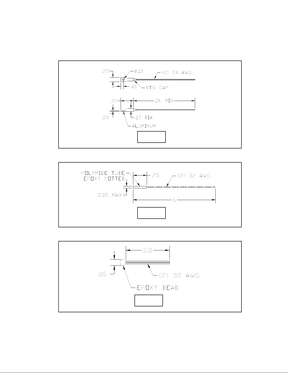
APPENDIX G Thermistor Styles for TC-24-25
MP-2379MP-2379MP-2379
MP-2444MP-2444
MP-2542MP-2542MP-2542
34
Page 35

Temperature (°C) versus Resistance (ohms)
for MP-2379, MP-2444, and MP2542 Thermistors
-20 146735 1 46709 22 17136 43 7075 64 3227 85 1601
-20 146735 1 46709 22 17136 43 7075 64 3227 85 1601
-19 138447 2 44397 23 16388 44 6801 65 3115 86 1551
-19 138447 2 44397 23 16388 44 6801 65 3115 86 1551
-18 130677 3 42213 24 15676 45 6539 66 3008 87 1503
-18 130677 3 42213 24 15676 45 6539 66 3008 87 1503
-17 123390 4 40150 25 15000 46 6289 67 2905 88 1457
-17 123390 4 40150 25 15000 46 6289 67 2905 88 1457
-16 116554 5 38199 26 14356 47 6049 68 2806 89 1412
-16 116554 5 38199 26 14356 47 6049 68 2806 89 1412
-15 110138 6 36354 27 13744 48 5820 69 2711 90 1369
-15 110138 6 36354 27 13744 48 5820 69 2711 90 1369
-14 104113 7 34608 28 13161 49 5600 70 2620 91 1328
-14 104113 7 34608 28 13161 49 5600 70 2620 91 1328
-13 98454 8 32957 29 12606 50 5391 71 2532 92 1288
-13 98454 8 32957 29 12606 50 5391 71 2532 92 1288
-12 93137 9 31394 30 12078 51 5190 72 2448 93 1250
-12 93137 9 31394 30 12078 51 5190 72 2448 93 1250
-11 88138 10 29914 31 11574 52 4997 73 2367 94 1212
-11 88138 10 29914 31 11574 52 4997 73 2367 94 1212
-10 83438 11 28512 32 11095 53 4813 74 2288 95 1176
-10 83438 11 28512 32 11095 53 4813 74 2288 95 1176
-9 79016 12 27183 33 10637 54 4637 75 2213 96 1142
-9 79016 12 27183 33 10637 54 4637 75 2213 96 1142
-8 74855 13 25925 34 10202 55 4467 76 2141 97 1108
-8 74855 13 25925 34 10202 55 4467 76 2141 97 1108
-7 70938 14 24731 35 9786 56 4305 77 2072 98 1076
-7 70938 14 24731 35 9786 56 4305 77 2072 98 1076
-6 67249 15 23600 36 9389 57 4150 78 2005 99 1045
-6 67249 15 23600 36 9389 57 4150 78 2005 99 1045
-5 63773 16 22526 37 9011 58 4001 79 1940 100 1014
-5 63773 16 22526 37 9011 58 4001 79 1940 100 1014
-4 60498 17 21508 38 8650 59 3858 80 1878
-4 60498 17 21508 38 8650 59 3858 80 1878
-3 57410 18 20541 39 8306 60 3721 81 1818
-3 57410 18 20541 39 8306 60 3721 81 1818
-2 54498 19 19623 40 7976 61 3590 82 1761
-2 54498 19 19623 40 7976 61 3590 82 1761
-1 51750 20 18751 41 7662 62 3464 83 1705
-1 51750 20 18751 41 7662 62 3464 83 1705
0 49157 21 17923 42 7362 63 3343 84 1652
0 49157 21 17923 42 7362 63 3343 84 1652
Note: Tolerance is ±650 Ω, corresponding to ±1 °C
over a 0 °C to 100 °C range.
35
 Loading...