


Annex No.4a
Page 1 of 41
Functional description / User’s manual
Radio Transceiver Module AMB2520-T1

Manual for AMB8420 and AMB2520
Version 3.6
SW-V3.0, 3.1, 3.2
AMBER wireless GmbH
Albin-Köbis-Strasse 18
D-51147 Cologne
Phone: +49 2203 6991950
Fax: +49 2203 459883
E-mail: info@amber-wireless.de
Internet:
http://www.amber-wireless.de

Table of Contents
1 Summary.............................................................................................................................................. 4
2 Operating Modes ................................................................................................................................. 4
2.1 Transparent, Buffered Data Transfer ................................................................................................. 5
2.2 Command Mode................................................................................................................................. 5
2.2.1 Switching to the Command Mode............................................................................................... 5
2.2.2 Exiting the Command Mode ....................................................................................................... 6
2.2.3 Communication in the Command Mode ..................................................................................... 6
3 Addressing Modes ............................................................................................................................... 7
3.1 Monitoring Wireless Communication ................................................................................................. 7
4 Electrical Parameters........................................................................................................................... 7
4.1 Input Voltage ...................................................................................................................................... 7
4.2 Power Consumption ........................................................................................................................... 8
4.2.1 AMB8420 .................................................................................................................................... 8
4.2.2 AMB2520 .................................................................................................................................... 8
5 Dimensions and Weight ....................................................................................................................... 8
6 Pinout................................................................................................................................................... 9
7 Serial Interface................................................................................................................................... 11
7.1 UART................................................................................................................................................ 11
7.1.1 Supported Data Rates .............................................................................................................. 11
7.1.2 Supported Data Formats .......................................................................................................... 11
7.2 SPI Interface .................................................................................................................................... 11
8 Setting the HF Parameters ................................................................................................................ 12
8.1 AMB8420.......................................................................................................................................... 12
8.1.1 "g1" Band .................................................................................................................................. 12
8.1.2 "g3" Band .................................................................................................................................. 12
8.1.3 "g4" Band .................................................................................................................................. 12
8.1.4 "g" Band .................................................................................................................................... 12
8.2 AMB2520.......................................................................................................................................... 13
9 Timing Parameters............................................................................................................................. 14
9.1 Reset Behaviour............................................................................................................................... 14
9.1.1 Power-On Reset ....................................................................................................................... 14
9.1.2 Reset via /RESET Pin............................................................................................................... 14
9.2 Wake-up from the Sleep Mode ........................................................................................................ 15
9.3 Latencies During Data Transfer / Packet Generation ...................................................................... 15
9.3.1 Transparent Operating Mode.................................................................................................... 15
9.3.2 Command Mode ....................................................................................................................... 16
10 Battery Operation............................................................................................................................... 16
10.1 Active Mode ................................................................................................................................... 16
10.2 Stand-By......................................................................................................................................... 16
10.3 WOR Mode .................................................................................................................................... 16
10.4 Sleep Mode .................................................................................................................................... 16
11 The Command Interface .................................................................................................................... 17
11.1 Data Transfer in the Command Mode............................................................................................ 17
11.1.1 CMD_DATA_REQ .................................................................................................................. 17
11.1.2 CMD_DATAEX_REQ ............................................................................................................. 17
11.1.3 CMD_DATAEX_IND ............................................................................................................... 18
11.1.4 CMD_DATARETRY_REQ ...................................................................................................... 18
11.2 CMD_SET_MODE_REQ ............................................................................................................... 19
11.3 CMD_RESET_REQ ....................................................................................................................... 19
11.4 CMD_SET_CHANNEL_REQ ......................................................................................................... 20
11.5 CMD_SET_DESTNETID_REQ ...................................................................................................... 20
11.6 CMD_SET_DESTADDR_REQ ...................................................................................................... 20
11.7 CMD_SET_REQ ............................................................................................................................ 21
AMB8420/2520 Manual V3.6 Page 2 of 40 Last update: 25/3/2008

11.8 CMD_GET_REQ ............................................................................................................................ 22
11.9 CMD_SERIALNO_REQ ................................................................................................................. 22
11.10 CMD_RSSI_REQ ......................................................................................................................... 23
11.11 CMD_ERRORFLAGS_REQ ........................................................................................................ 25
12 Configuration Parameters .................................................................................................................. 25
12.1 Non-Volatile Configuration Parameters ......................................................................................... 25
12.1.1 UART_CTL ............................................................................................................................. 28
12.1.2 UART_TCTL ........................................................................................................................... 28
12.1.3 UART_MCTL .......................................................................................................................... 28
12.1.4 UART_BR0 ............................................................................................................................. 28
12.1.5 UART_BR1 ............................................................................................................................. 29
12.1.6 UART_PktMode ...................................................................................................................... 29
12.1.7 UART_PktSize ........................................................................................................................ 29
12.1.8 UART_RTSLimit ..................................................................................................................... 29
12.1.9 UART_ETXChar ..................................................................................................................... 29
12.1.10 UART_Timeout ..................................................................................................................... 29
12.1.11 UART_DIDelay ..................................................................................................................... 30
12.1.12 MAC_NumRetrys .................................................................................................................. 30
12.1.13 MAC_AddrMode ................................................................................................................... 30
12.1.14 MAC_DestNetID ................................................................................................................... 30
12.1.15 MAC_DestAddrLSB .............................................................................................................. 30
12.1.16 MAC_SourceNetID ............................................................................................................... 30
12.1.17 MAC_SourceAddrLSB .......................................................................................................... 30
12.1.18 MAC_ACKTimeout ............................................................................................................... 31
12.1.19 PHY_FIFOPrecharge............................................................................................................ 31
12.1.20 PHY_PAPower ..................................................................................................................... 31
12.1.21 PHY_DefaultChannel............................................................................................................ 31
12.1.22 PHY_CCARSSILevel ............................................................................................................ 31
12.1.23 OpMode ................................................................................................................................ 31
12.1.24 MSP_RSELx ......................................................................................................................... 31
12.1.25 MSP_DCOCTL ..................................................................................................................... 32
12.1.26 WOR_Prescaler .................................................................................................................... 32
12.1.27 WOR_Countdown ................................................................................................................. 32
12.1.28 WOR_RXOnTime ................................................................................................................. 32
12.1.29 CfgFlags................................................................................................................................ 33
13 Start-up .............................................................................................................................................. 34
13.1 Minimal Configuration .................................................................................................................... 34
13.2 Transfer of Large Amounts of Data................................................................................................ 34
13.3 Deployment of Several Modules, Use of Addresses, Channel Switching ..................................... 34
13.4 Use of the Low-Power Functionality .............................................................................................. 34
13.5 Minimising Latencies ...................................................................................................................... 34
14 Firmware Update ............................................................................................................................... 34
14.1 Update of Earlier FW Versions (< 3.0.0) ........................................................................................ 35
15 Manufacturing Information ................................................................................................................. 36
15.1 Footprint Dimensioning Proposal................................................................................................... 36
15.2 Soldering ........................................................................................................................................ 37
16 Version History................................................................................................................................... 38
16.1 Software ......................................................................................................................................... 38
16.2 Manual............................................................................................................................................ 38
17 References......................................................................................................................................... 38
18 Declaration of Conformity .................................................................................................................. 39
19 Important Information......................................................................................................................... 40
19.1 Exclusion of Liability ....................................................................................................................... 40
19.2 Trademarks .................................................................................................................................... 40
19.3 Usage Restriction ........................................................................................................................... 40
AMB8420/2520 Manual V3.6 Page 3 of 40 Last update: 25/3/2008

Abbreviations
CS Checksum
DC Duty cycle Relative frequency reservation period
1 Summary
The AMB8420/AMB2520 module was designed as a radio submodule for wireless
communication between devices like controls, remote controls, sensors etc. It offers several
addressing modes and relieves the host system of radio-specific tasks such as
• checksum calculation,
• address resolution, and
• repetition of unacknowledged telegrams.
It can be deployed wherever the wireless exchange of small data packets (up to 128 bytes)
between two or more parties is required.
A serial interface (UART) whose data rate and format can be adjusted flexibly is available for
communicating with the host system; from SW version 3.2, a variant with SPI functionality is
available.
By means of the Windows program "ACC", the HF data rate can be adjusted from 4.8 to 250
kbps.
Thanks to its small size and the integrated antenna, the module can easily be installed in
existing systems without any external circuits.
2 Operating Modes
The device can be used in the following operating modes:
1. Transparent, buffered data transfer
2. Command mode
The operating mode after power-up can be configured by means of the
(
see 12.1.23).
Upon start-up in the command mode, the module responds with the respective telegram (see
11.2).
OpMode
parameter
AMB8420/2520 Manual V3.6 Page 4 of 40 Last update: 25/3/2008

2.1 Transparent, Buffered Data Transfer
In this mode, data is received via the serial interface and initially buffered. As soon as specific
conditions are met (see 9.3), the HF telegram is generated with a preamble, checksum, and
address information (optional).
The number of characters transmitted in the wireless telegram in addition to the actual payload
data depends on the selected addressing method and the data rate, and varies between 12 and
16 bytes (packet overhead).
If required, the HF telegram can be acknowledged by the recipient module (see 12.1.12). If no
acknowledgement is received, the telegram will automatically be repeated upon expiry of a
timeout (see 12.1.18).
The buffer size at the UART interface is 128 bytes, i.e. the maximum size of transmitted data
packets is 128 bytes (payload data only, without packet overhead).
As soon as the transmission of a packet has begun, the serial interface cannot receive any
further data. The /RTS signal indicates that the buffer is in use.
N.B.: As long as the receiver module is busy sending characters via the serial interface,
wireless data reception is not possible. For example, this effect is noticeable when
sending a long data packet and subsequently a short data packet. In this case, the
receiver module may still be busy sending the first packet via UART or SPI, and the
second packet may be lost.
2.2 Command Mode
This operating mode primarily serves module configuration. It can also be used for wireless
transmission of payload data.
2.2.1 Switching to the Command Mode
The unit switches to the command mode
• when a falling edge is detected on the /CONFIG pin, or
• when a break signal is detected on the UART. A break condition exists if the RX input of
the module is kept low for at least 10 more bits after a failure of the stop bit.
Detection of both the falling edge on the /CONFIG pin and of the break signal can be disabled
(see 12.1.29).
The successful switchover is acknowledged by means of a corresponding command (see 11.2).
The switchover can only occur when no data is being received by wireless transmission or serial
interface (approximately 100 µs after /RTS goes low and indicates readiness).
AMB8420/2520 Manual V3.6 Page 5 of 40 Last update: 25/3/2008

2.2.2 Exiting the Command Mode
The command mode can be exited
1. by sending the corresponding command (see 11.2),
2. on detection of another falling edge on the /CONFIG pin, or
3. on detection of another break signal on the UART.
This procedure is again confirmed by means of the corresponding acknowledgement.
2.2.3 Communication in the Command Mode
In the Command Mode, communication with the module occurs in the form of predefined
commands. These commands must be sent in telegrams according to the format described in
Table 1.
Start signal Command No. of data Data (var.) Checksum
Table 1: Telegram Format in the Command Mode
Start signal: STX = 0x02
Command: One of the predefined commands according to section 11
No. of data: Specifies the number of data in the following field of variable length and is limited
to 128 in order to prevent buffer overflow.
Data: Variable number of data or parameters (maximum 128 characters)
Checksum: XOR relation of the preceding fields including the start signal STX, i.e. 0x02 ^
command ^ no. of data ^ data byte 0 ...
Using a specific command, data can also be sent via HF, i.e. the module can be operated
entirely in the Command Mode. This is useful for realising quick channel changes, for example.
If no new signal is received for
UART_Timeout
milliseconds (see 12.1.10) after receiving the
STX signal, the unit will wait for a new start signal.
AMB8420/2520 Manual V3.6 Page 6 of 40 Last update: 25/3/2008

3 Addressing Modes
The following addressing modes are available:
1. No addressing (mode 0): Each module receives the transmitted HF telegram and
delivers the received data to the host system via UART. No address information is
transmitted in the wireless telegram.
2. 1-byte address (mode 1): The receiving module will only deliver the data to the host
system via UART if the destination address configured at the sender
(
MAC_DestAddrLSB
(
MAC_SourceAddrLSB
specified as destination address. Both the destination address and the source address
are transmitted in the wireless telegram (total = 2 bytes).
3. 2-byte address (mode 2): The receiving module will only deliver the data to the host
system via UART if both the destination network ID and the destination address
correspond to the source addresses (
MAC_SourceAddrLSB
specified as destination address. A total of 4 bytes of address information are
transmitted in the wireless telegram.
, see 12.1.15) corresponds to the source address
, see 12.1.17) or the address 255 (broadcast address) was
MAC_SourceNetID
, see 12.1.16 and 12.1.17) or the broadcast address 255 was
and
The addressing mode to be used can be set with the
12.1.13).
N.B.: The receiver and transmitter modules must be operated in the same addressing
mode!
MAC_AddrMode
parameter (see
3.1 Monitoring Wireless Communication
From firmware version 3.2, the address resolution can be disabled ("packet sniffer") with bit 7 in
the configuration flags (see 12.1.29). A module configured in this way will receive all data
packets and forward them to the serial interface, regardless of the addressing mode.
4 Electrical Parameters
4.1 Input Voltage
The input voltage of the module ranges from 2.7 to 3.6 V.
In order to ensure a constant processor frequency (and UART clock rate) over the entire voltage
range, the clock rate is continuously readjusted on the basis of the available watch crystal.
Voltage changes during the reception or output over the serial interface can result in a change
of the clock rate between two characters.
N.B.: A clean supply voltage is needed for the module to function correctly. Using a 100
µF blocking capacitor close to the VCC pin is a useful measure (especially when using
RS232 converters or clocked DC-DC converters).
AMB8420/2520 Manual V3.6 Page 7 of 40 Last update: 25/3/2008

4.2 Power Consumption
4.2.1 AMB8420
See data sheet [4].
4.2.2 AMB2520
See data sheet [5].
N.B.: To minimise power consumption in Sleep Mode, the input signals of the module
(/CONFIG, SLEEP, TRX_DISABLE und /DATA_REQUEST) must be set to the levels
defined in Table 2. Open (floating) pins result in increased power consumption.
5 Dimensions and Weight
See data sheets [4] and [5].
AMB8420/2520 Manual V3.6 Page 8 of 40 Last update: 25/3/2008
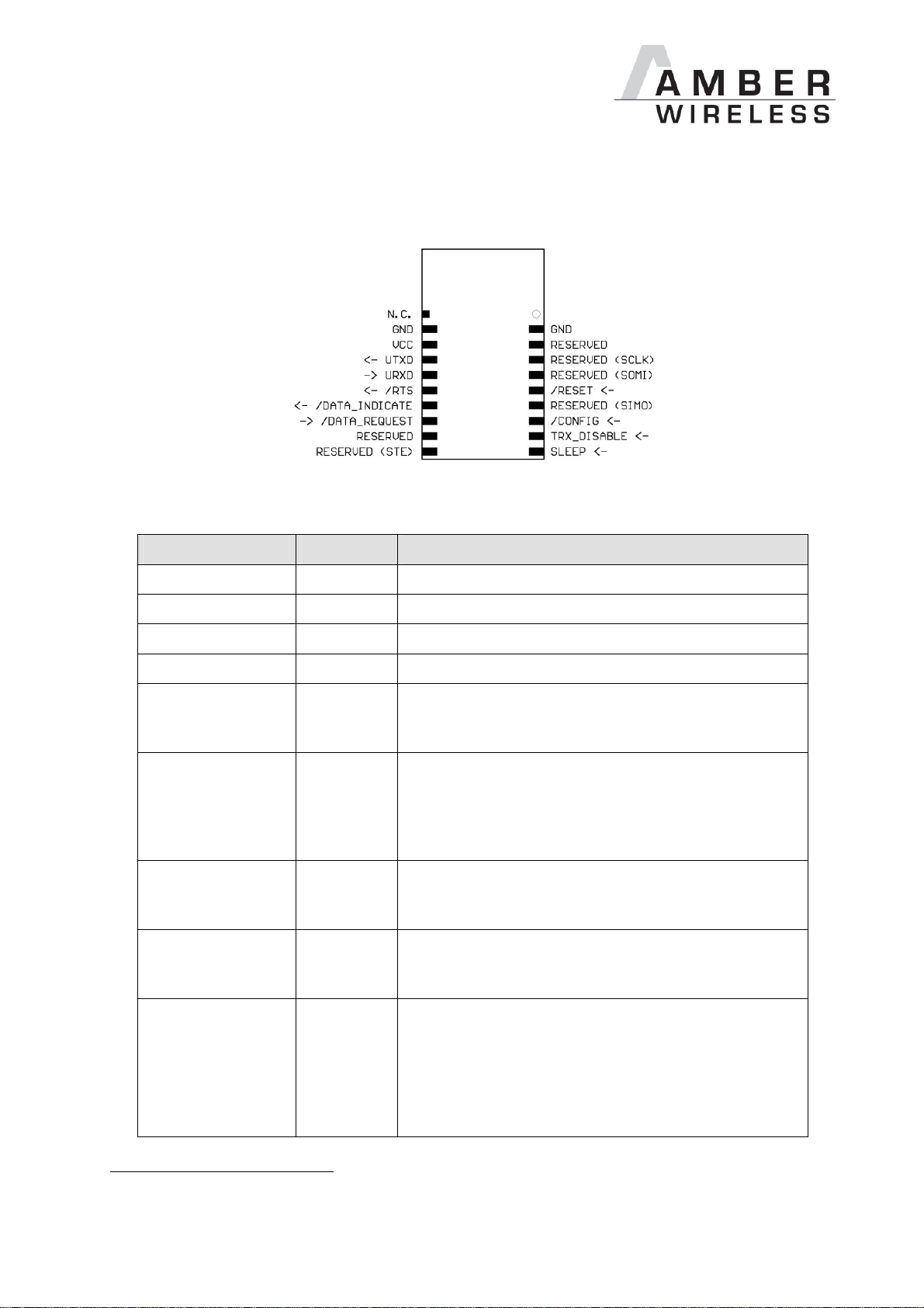
6 Pinout
Figure 1 Pinout
Designation I/O Description
VCC1 Supply Supply voltage
GND Supply Ground
UTXD Output Output serial interface
URXD Input Input serial interface
/RESET Input A low level on this pin performs a restart of the
module. Internally, this pin is connected to VCC via a
100 kΩ pull-up resistor. Leave open if not needed.
/CONFIG Input Used to switch the module to the Command Mode
(falling edge). Alternatively, this can be done by
means of a UART break signal. Connect to GND if
not needed. The function can be disabled (see
12.1.29).
SLEEP Input
Activates the Sleep Mode (high level). Connect to
GND if not needed. The function can be disabled
(see 12.1.29).
TRX_DISABLE Input Switches the HF part off (high level) as long as no
data is to be sent. Connect to GND if not needed.
The function can be disabled (see 12.1.29).
/DATA_REQUEST
Input Prompts the wireless transmission of the data
received via the UART (falling edge). As long as no
new data is received via UART or wireless
transmission, the buffer content remains valid and
can be resent by means of a new signal. Connect to
GND if not needed. The function can be disabled
(see 12.1.29). Without function in the command
1
100µF blocking capacitor recommended between VCC and GND in close proximity to the module
AMB8420/2520 Manual V3.6 Page 9 of 40 Last update: 25/3/2008

mode.
/RTS Output Ready to send (active low). When /RTS is low, data
can be received via UART. /RTS goes high as soon
as the UART buffer is full or when the wireless
reception of a telegram is detected. From this
moment, all data coming in via UART will be
ignored. Timeout after falling edge: 100 µs.
/DATA_INDICATE
RESERVED Currently not used. These pins must be left open (do
N.C. Open, optional aerial connection; use only after
Output Goes low as soon as a valid frame is received via
wireless transmission and remains low as long as
the output via UART continues. Can be used to
prepare a "sleeping" host system for the output of
data. The delay between the rising edge and the
beginning of output via UART can be configured
(see
UART_DIDelay
, 12.1.11). During the
transmission process, this pin signals the successful
acknowledgement of the wireless telegram (if such
was requested, see
MAC_NumRetrys
, 12.1.12): in
this case, /DATA_INDICATE is set to low before the
falling edge of the /RTS pin and goes back high
when new data is received via wireless transmission
or UART, at the latest.
not connect). Some of these pins are used for the
optional SPI interface.
consultation.
Table 2 Pinout
AMB8420/2520 Manual V3.6 Page 10 of 40 Last update: 25/3/2008

7 Serial Interface
7.1 UART
7.1.1 Supported Data Rates
The data rate is adjusted by directly configuring the respective registers of the utilised
microprocessor (see
In this way, the data rate can be adjusted freely from 0.5 to 115200 baud.
As the UART speed is derived from the speed of the utilised clock quartz, there may be
variations of up to 0.5%.
When using the PC program "ACC", the following data rates can be selected directly via dropdown menu:
110, 300, 600, 1200, 2400, 4800, 9600, 14400, 19200, 28800, 38400, 56000, 57600, and
115200 baud.
With this selection, the three registers above are automatically set to the optimum value.
UART_TCTL, UART_MCTL, UART_BR0
, and
UART_BR1
; from 12.1.1).
Moreover, the "ACC" program also provides a dialogue for calculating any baud rates.
The default baud rate of the module is 9600 (AMB8420)/38400 (AMB2520).
The output of characters on the serial interface takes place with secondary priority. For this
reason, short interruptions may occur between the output of individual characters (e.g. in the
event of an interrupt).
7.1.2 Supported Data Formats
All data formats offered by the processor are supported:
• 7 or 8 bits
• No, even, or odd parity
• 1 or 2 stop bits
In ACC, the following data formats can be selected directly via the drop-down menu:
8n1, 8o1, 8e1, 8n2, 8o2, 8e2, 7n1, 7o1, 7e1, 7n2, 7o2, 7e2.
The data format, too, can be set by directly configuring the respective microprocessor registers
(see
UART_CTL
The default data format is 8 data bits, no parity, 1 stop bit ("8n1").
, 12.1.1).
7.2 SPI Interface
Instead of the UART interface, the module also has an SPI interface. This interface is supported
from software version 3.2 (separate firmware, can be installed with the Windows program
"ACC"). See [6].
AMB8420/2520 Manual V3.6 Page 11 of 40 Last update: 25/3/2008
8 Setting the HF Parameters
The HF parameters (data rate, usable frequency range, etc.) can be configured with the PC
program "ACC". Depending on the configured data rate, it can also be used to change
additional parameters, e.g.
PHY_FIFOPrecharge
8.1 AMB8420
The following sections describe the permissible data rates and frequency ranges. In the factory
state, the HF data rate is 38.4 kbps.
N.B.: The maximum channel reservation period in the 868 MHz frequency band is subject
to regulations. This period is also referred to as duty cycle (DC) and designates the
maximum transmission time of a device in relation to one hour. A 1% DC, for example,
permits the use of a channel for 36 seconds per hour.
MAC_ACKTimeout, PHY_DefaultChannel
.
, or
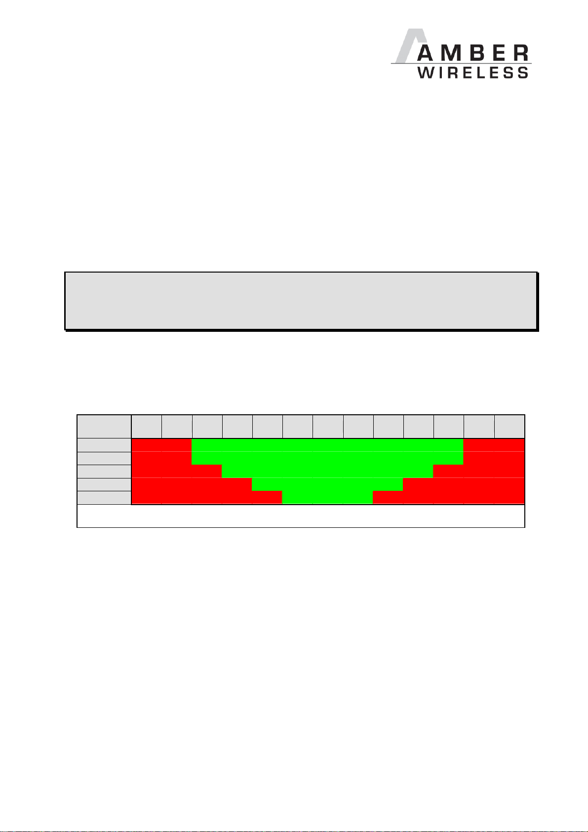
8.1.1 "g1" Band
This frequency band ranges from 868.0 to 868.6 MHz and permits a 1% duty cycle.
Channel no.
\ data rate
4.8 kbps 868.00 868.05 868.10 868.15 868.20 868.25 868.30 868.35 868.40 868.45 868.50 868.55 868.60
10 kbps 868.00 868.05 868.10 868.15 868.20 868.25 868.30 868.35 868.40 868.45 868.50 868.55 868.60
38.4 kbps 868.00 868.05 868.10 868.15 868.20 868.25 868.30 868.35 868.40 868.45 868.50 868.55 868.60
76.8 kbps 868.00 868.05 868.10 868.15 868.20 868.25 868.30 868.35 868.40 868.45 868.50 868.55 868.60
100 kbps 868.00 868.05 868.10 868.15 868.20 868.25 868.30 868.35 868.40 868.45 868.50 868.55 868.60
100 101 102 103 104 105 106 107 108 109 110 111 112
Table 3 Channel table "g1" band. Permissible channels are highlighted in green
8.1.2 "g3" Band
This frequency band ranges from 869.4 to 869.65 MHz and permits a 10% duty cycle. The
channel table will follow.
8.1.3 "g4" Band
This frequency band ranges from 869.7 to 870 MHz and permits a 100% duty cycle. The
channel table will follow.
8.1.4 "g" Band
This frequency band ranges from 863 to 868.6 MHz and permits a 0.1% duty cycle or from 865
to 868.6 MHz with a 1% duty cycle. The channel table will follow.
AMB8420/2520 Manual V3.6 Page 12 of 40 Last update: 25/3/2008
 Loading...