

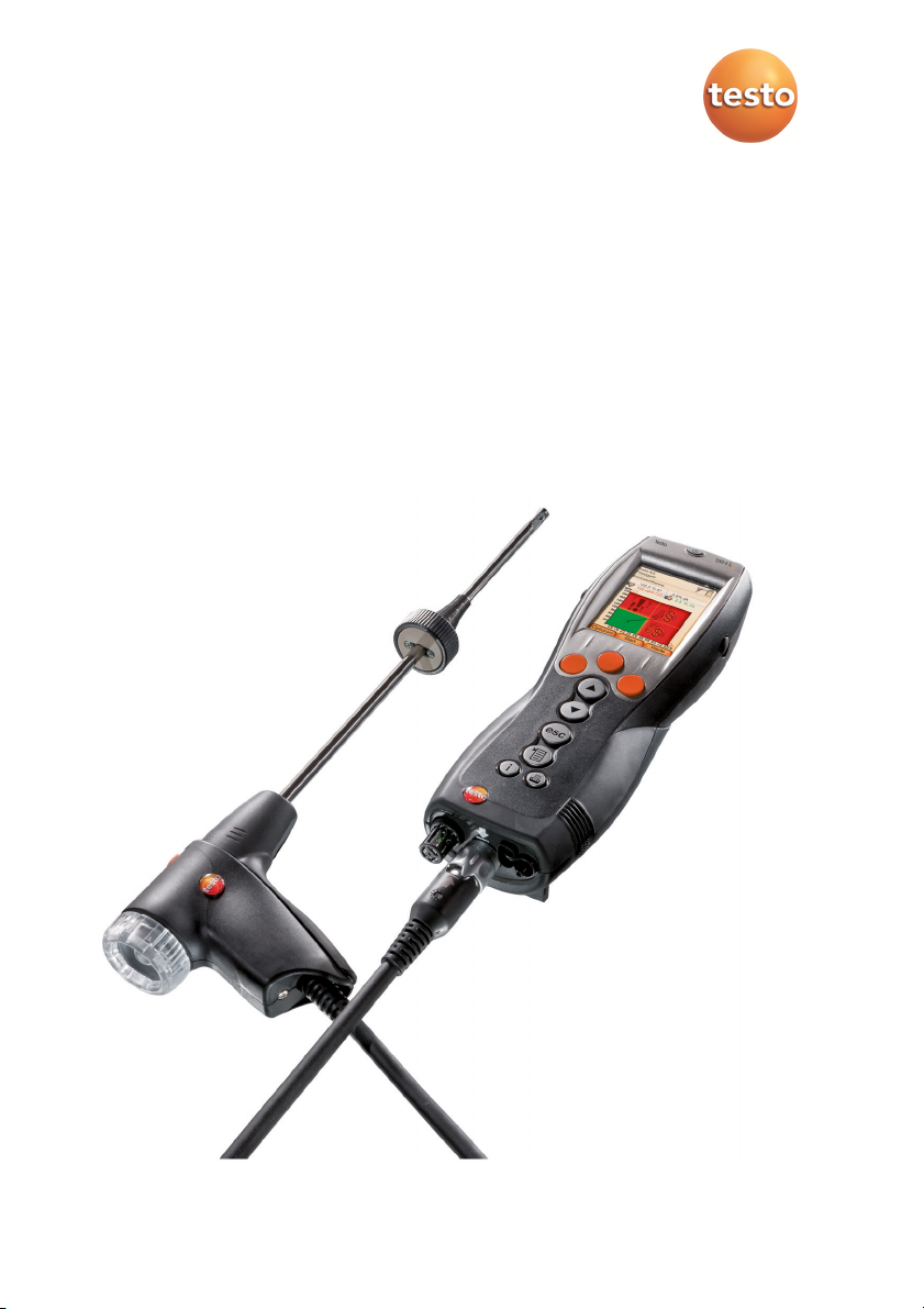
testo 330 · Flue gas analyzer
Instruction manual

2

1 Contents
Pos: 1 /TD/Überschriften/1. Inhalt @ 0\mod_11775878 17070_79.docx @ 1243 @ 1 @ 1
1 Contents
1 Contents ................................................................................... 3
2 Safety and the environment ...................................................... 7
2.1. About this document ............................................................ 7
2.2. Ensure safety ......................................................................... 8
2.3. Protecting the environment .................................................. 9
3 Specifications ............................................................................ 9
3.1. Use......................................................................................... 9
3.2. Technical data ..................................................................... 11
3.2.1. Examinations and licenses ......................................................................................... 11
3.2.2. Bluetooth® module (option) ....................................................................................... 11
3.2.2.1. Bluetooth®-Type: BlueGiga ......................................................................... 11
3.2.2.2. Bluetooth®-Type: BlueMod+SR ................................................................... 12
3.2.3. Declaration of Conformity ......................................................................................... 15
3.2.4. Measuring ranges and resolution .............................................................................. 17
3.2.5. Accuracy and response time ...................................................................................... 17
3.2.6. Other instrument data ............................................................................................... 19
4 Product description ................................................................. 20
4.1. Case 0516 3300 (accessory) ................................................ 20
4.1.1. Bottom level view ...................................................................................................... 21
4.1.2. Top level view ............................................................................................................ 22
4.2. Case 0516 3301 (accessory) ................................................ 23
4.2.1. Bottom level view ...................................................................................................... 23
4.2.2. Middle level view ....................................................................................................... 24
4.2.3. Top level view ............................................................................................................ 25
4.3. Measuring instrument......................................................... 26
4.3.1. Overview ................................................................................................................... 26
4.3.2. Keypad ....................................................................................................................... 27
4.3.3. Display ....................................................................................................................... 28
4.3.4. Device connections .................................................................................................... 29
4.3.5. Interfaces ................................................................................................................... 29
4.3.6. Components .............................................................................................................. 30
4.3.7. Carrying strap (0440 0581) ........................................................................................ 30
4.4. Modular flue gas probe ....................................................... 31
3

1 Contents
5 First steps ................................................................................ 32
5.1. Commissioning .................................................................... 32
5.2. Getting to know the product .............................................. 32
5.2.1. Mains unit / rechargeable battery ............................................................................. 32
5.2.1.1. Changing the battery.................................................................................. 32
5.2.1.2. Charging batteries ...................................................................................... 33
5.2.1.3. Mains operation ......................................................................................... 33
5.2.2. Connecting probes / sensors ...................................................................................... 34
5.2.3. Switching on .............................................................................................................. 35
5.2.4. Calling up a function .................................................................................................. 35
5.2.5. Entering values .......................................................................................................... 35
5.2.6. Show graphic ............................................................................................................. 36
5.2.7. Printing / saving data ................................................................................................. 37
5.2.8. Remembering data (clipboard) .................................................................................. 37
5.2.9. Confirming an error message ..................................................................................... 37
5.2.10. Switching off .............................................................................................................. 38
5.3. Address/Location ................................................................ 38
5.4. Measurement records ........................................................ 40
5.5. Instrument diagnosis .......................................................... 41
6 Using the product .................................................................... 42
6.1. Performing settings ............................................................. 42
6.1.1. Assigning the right function key ................................................................................. 42
6.1.2. Instrument settings .................................................................................................... 42
6.1.2.1. Readings display ......................................................................................... 42
6.1.2.2. Alarm limits ................................................................................................ 44
6.1.2.3. Units .......................................................................................................... 44
6.1.2.4. Date / time ................................................................................................. 44
6.1.2.5. Energy management .................................................................................. 45
6.1.2.6. Display brightness ...................................................................................... 45
6.1.2.1. Choose measurement type ........................................................................ 45
6.1.2.2. Printer ........................................................................................................ 46
6.1.2.3. Bluetooth® .................................................................................................. 46
6.1.2.4. Language .................................................................................................... 46
6.1.2.5. Country version .......................................................................................... 47
6.1.2.6. Password protection .................................................................................. 47
6.1.3. Sensor settings ........................................................................................................... 48
6.1.3.1. NO2 addition .............................................................................................. 48
6.1.3.2. O2 reference ............................................................................................... 48
6.1.3.3. Sensor protection ....................................................................................... 48
6.1.3.4. Recalibration / adjustment ........................................................................ 49
4

1 Contents
6.1.4. Fuels .......................................................................................................................... 50
6.1.5. Programs ................................................................................................................... 51
6.2. Measuring ........................................................................... 51
6.2.1. Preparing for measurement....................................................................................... 51
6.2.1.1. Zeroing phases ........................................................................................... 52
6.2.1.2. Using the modular flue gas probe .............................................................. 52
6.2.1.3. Configuring the reading display ................................................................. 53
6.2.1.4. Setting location and fuel ............................................................................ 54
6.2.2. Flue gas ...................................................................................................................... 54
6.2.3. Draught-Measurement .............................................................................................. 56
6.2.4. Micro pressure probe ................................................................................................ 57
6.2.5. BImSchV (testo 330-2 LL) ........................................................................................... 57
6.2.6. CO undiluted .............................................................................................................. 58
6.2.7. Smoke No. / HCT ........................................................................................................ 59
6.2.8. Differential pressure .................................................................................................. 60
6.2.9. Differential temperature ........................................................................................... 61
6.2.10. O2 air ......................................................................................................................... 61
6.2.11. Gas flow ..................................................................................................................... 62
6.2.12. Oil flow ...................................................................................................................... 62
6.2.13. CO ambient ................................................................................................................ 63
6.2.14. CO2 ambient .............................................................................................................. 64
6.2.15. Automatic furnaces ................................................................................................... 64
6.2.16. Solid fuel measurement ............................................................................................. 66
6.2.17. Gas pipe tests ............................................................................................................ 67
6.2.17.1. Tightness test 1 .......................................................................................... 67
6.2.17.2. Tightness test 2 .......................................................................................... 68
6.2.17.3. Let By Test ................................................................................................. 69
6.2.17.4. Leak detection ........................................................................................... 69
6.3. Transferring data ................................................................. 70
6.3.1. Report printer ............................................................................................................ 70
6.3.2. PC / Pocket PC ........................................................................................................... 70
7 Maintaining the product ......................................................... 70
7.1. Cleaning the measuring instrument .................................... 70
7.2. Replacing sensors ................................................................ 71
7.3. Recalibrating / adjusting sensors ........................................ 71
7.4. Replacing additional filter ................................................... 72
7.5. Cleaning the modular flue gas probe .................................. 72
7.6. Replacing the probe module ............................................... 73
5

1 Contents
7.7. Changing the thermocouple ............................................... 73
7.8. Condensate container ......................................................... 74
7.9. Checking/replacing the particle filter ................................. 75
8 Tips and assistance .................................................................. 75
8.1. Questions and answers ....................................................... 75
8.2. Accessories and spare parts ................................................ 76
8.3. Updating the instrument software ..................................... 80
Pos: 2 /TD/--- Seitenwechsel --- @ 0\mod_1173774430601_0.docx @ 283 @ @ 1
6
2 Safety and the environment
Pos: 3 /TD/Überschriften/2. Sicherheit und Umwelt @ 0\m od_1173774719351_79.d ocx @ 292 @ 1 @ 1
2 Safety and the environment
Pos: 4 /TD/Überschriften/2.1 Zu diesem Dokument @ 0\mod_1 173775252351_79.d ocx @ 346 @ 2 @ 1
2.1. About this document
Pos: 5 /TD/Sicherheit und Umwelt/Zu diesem Dokument/t esto 330 Landesversion DE, Sprache en (LV-spezif isch!) @ 7\mod_128403439 2317_79.docx @ 72238 @ @ 1
This document describes the products testo 330-1 LL and
testo 330-2 LL with the instrument setting Country version |
Pos: 6 /TD/Sicherheit und Umwelt/Zu diesem Dokument/Ver wendung/Verwendun g (Standard) @ 0\mod_117377 5068554_79.doc x @ 337 @ 5 @ 1
Pos: 7 /TD/Sicherheit und Umwelt/Zu diesem Dokument/Sy mbole und Schreibkonven tionen/Symbole und Sc hreibkonv. [testo 330] @ 6\mod_1278662875713 _79.docx @ 64907 @ 5 @ 1
Germany.
Use
> Please read this documentation through carefully and
familiarize yourself with the product before putting it to use. Pay
particular attention to the safety instructions and warning advice
in order to prevent injuries and damage to the products.
> Keep this document to hand so that you can refer to it when
necessary.
> Hand this documentation on to any subsequent users of the
product.
Symbols and writing standards
Representati
Explanation
on
Warning advice, risk level according to the
signal word:
Warning! Serious physical injury may occur.
Caution! Minor physical injury or damage to the
equipment may occur.
> Apply the specified precautionary measures.
Note: Basic or further information.
testo 330-1 LL
The description only applies for the specified
instrument model testo 330-1 LL or
testo 330-2 LL.
1. ...
2. ...
Action: several steps, the sequence must be
followed.
> ... Action: one step or optional step.
- ... Result of an action.
Menu Elements of equipment , equipment display or
program interface.
7

2 Safety and the environment
Representati
Explanation
on
[OK] Control keys on equipment or control buttons in
program interface.
... | ... Functions / paths within a menu.
“...” Example entries
Pos: 8 /TD/Überschriften/2.2 Sicherheit gewährlei sten @ 0\mod_11737807 83960_79.docx @ 366 @ 2 @ 1
2.2. Ensure safety
Pos: 9 /TD/Sicherheit und Umwelt/Sicherheit gewähr leisten/Produkt besti mmungsgemäß verwenden @ 0\mod_1173781261848 _79.docx @ 386 @ @ 1
> Only operate the product properly, for its intended purpose and
within the parameters specified in the technical data. Do not
Pos: 10 /TD/Sicherheit und Umwelt/Sicherheit gewähr leisten/Gerät bei Besc hädigungen nicht i n Betrieb nehmen @ 0\mod_11869 85945375_79.docx @ 2252 @ @ 1
use any force.
> Do not operate the instrument if there are signs of damage at
Pos: 11 /TD/Sicherheit und Umwelt/Sicherheit gewähr leisten/Keine Mess ung an spannungsführenden Teilen @ 0\mod_11756925 64164_79.docx @ 592 @ @ 1
the housing, mains unit or feed lines.
> Do not perform contact measurements on non-insulated, live
Pos: 12 /TD/Sicherheit und Umwelt/Sicherheit gewähr leisten/Nicht mit Lö sungsmitteln lagern @ 0\ mod_1175692375179_79. docx @ 583 @ @ 1
parts.
> Do not store the product together with solvents. Do not use any
Pos: 13 /TD/Sicherheit und Umwelt/Sicherheit gewähr leisten/Nur beschr iebene Wartungsarbeit en durchführen @ 0\mod_ 1175692705195_79.doc x @ 601 @ @ 1
desiccants.
> Carry out only the maintenance and repair work on this
instrument that is described in the documentation. Follow the
prescribed steps exactly. Use only original spare parts
Pos: 14 /TD/Sicherheit und Umwelt/Sicherheit gewähr leisten/testo 350/ testo 350 Sicherheit @ 5\ mod_1261385845735_79. docx @ 53306 @ @ 1
from Testo.
> Any further or additional work must only be carried out by
authorised personnel. Testo will otherwise refuse to accept
responsibility for the proper functioning of the measuring
Pos: 15 /TD/Sicherheit und Umwelt/Sicherheit gewähr leisten/Nur in geschl ossenen, trockenen Räumen betreiben @ 0\mod_118 6985797828_79.doc x @ 2243 @ @ 1
instrument after repair and for the validity of certifications.
> Only use the device in closed, dry rooms and protect it from rain
Pos: 16 /TD/Sicherheit und Umwelt/Sicherheit gewähr leisten/Temperatur angaben auf Sonden/Füh lern @ 0\mod_117569329307 0_79.docx @ 610 @ @ 1
and moisture.
> Temperatures given on probes/sensors relate only to the
measuring range of the sensors. Do not expose handles and
feed lines to any temperatures in excess of 70 °C unless they
Pos: 17 /TD/Sicherheit und Umwelt/Sicherheit gewähr leisten/testo 330/ Sichtbarer Schaden @ 13\ mod_1369999619300_79. docx @ 162534 @ @ 1
are expressly permitted for higher temperatures.
> The testo 330 must be checked before commissioning for any
visible damage. Do not commission the testo 330 if there are
signs of damage on the housing, mains unit or supply lines.
Pos: 18 /TD/Sicherheit und Umwelt/Sicherheit gewähr leisten/vor Ort gül tige Sicherheitsbesti mmungen beachten @ 0\mod_1 186997107328_79.doc x @ 2298 @ @ 1
Electrical risk.
> Dangers may also arise from the systems being measured or
the measuring environment: Note the safety regulations valid in
your area when performing the measurements.
8

Pos: 19 /TD/Sicherheit und Umwelt/Sicherheit gewähr leisten/Option Blue tooth testo 330 @ 7\mod_1281 422320910_79.doc x @ 68203 @ 5 @ 1
For products with Bluetooth® (optional)
Changes or modifications that have been made without the explicit
consent of the responsible approval authority, may cause the
retraction of the type approval.
Data transfer may be disturbed by equipment that uses the same
ISM-band, e.g. WLAN, microwave ovens, ZigBee.
The use of radio communication links is not permitted, among
others, in aeroplanes and hospitals. For this reason the following
points must be ensured before entering:
> Switch off the device:
> Isolate the device from any external power sources (mains
Pos: 20 /TD/Überschriften/2.3 Umwelt schützen @ 0\mod_11 73780843645_79.doc x @ 375 @ 2 @ 1
2.3. Protecting the environment
Pos: 21.1 /TD/Sicherheit und Umwelt/Umwelt schützen/ Akkus/Batterien en tsorgen @ 0\mod_117569 3637007_79.docx @ 619 @ @ 1
cable, external rechargeable batteries, ...).
> Dispose of faulty rechargeable batteries/spent batteries in
Pos: 21.2 /TD/Sicherheit und Umwelt/Umwelt schützen/ Produkt entsorgen @ 0\ mod_1173780307072_79. docx @ 357 @ @ 1
accordance with the valid legal specifications.
> At the end of its useful life, send the product to the separate
collection for electric and electronic devices (observe local
Pos: 22 /TD/Überschriften/3. Leistungsbeschrei bung @ 0\mod_117377479155 4_79.docx @ 301 @ 1 @ 1
3 Specifications
Pos: 23 /TD/Überschriften/3.1 Verwendung @ 0\mod_117 6211016437_79.doc x @ 695 @ 2 @ 1
regulations) or return the product to Testo for disposal.
3 Specifications
3.1. Use
Pos: 24 /TD/Leistungsbeschreibung/Verwendung/ testo 3xx/testo 330_Ver wendung @ 6\mod_1278664 111617_79.doc x @ 64971 @ @ 1
The testo 330 is a handheld measuring device for the professional
flue gas analysis of furnace systems:
• Small furnaces (burning oil, gas, wood, coal)
The solid fuel measurement adapter (0600 9765) is
required for measurements on solid fuel systems. The
adapter protects the measuring instrument from harmful
substances (dust, organic compounds, etc.).
• Low-temperature and condensing boilers
• Gas water heaters
These systems can be adjusted using the testo 330 and checked
for compliance with the applicable limit values.
The following tasks can also be carried out with the testo 330:
• Regulating the O2-, CO- and CO2-, NO-, NOx- values in
furnace systems for the purpose of ensuring optimal operation.
• Draught measurement.
9

3 Specifications
• Measuring and regulating the gas flow pressure in gas water
• Measuring and optimising the flow and return temperatures of
• CO and CO2 environment measurement.
• Detection of CH4 (methane) and C3H8 (propane).
• The testo 330 can be used for measurements on CHP stations
heaters.
heating systems.
in accordance with the first German Federal Immission Control
Ordinance (BImschV).
• In principal, the CO sensor can also be used for
measurements on CHP stations. If you should carry out
more than 50 measurements on CHP stations per year,
please contact your nearest testo service centre or send the
testo 330 for checking to testo Service.
A worn NOx filter of the CO sensor can be ordered as a
spare part (order no. 0554 4150) and replaced.
Testo guarantees the functionality of its products
when used in accordance with their intended
purpose. This guarantee does not apply to features
of Testo products in combination with unauthorised
third-party products. Competitor products are not
authorised by Testo.
As is common practice, Testo generally excludes
support, warranty or guarantee claims relating to
functionality that has not been guaranteed by Testo
as part of the product offered. Claims shall also be
excluded in the event of improper use or handling of
the products, e.g. in combination with unauthorised
third-party products.
10
testo 330 must not be used:
• as a safety (alarm) instrument
®
testo 330 with Bluetooth
The use of the wireless module is subject to the
regulations and stipulations of the respective country of
use, and the module may only be used in countries for
which a country certification has been granted. The user
and every owner has the obligation to adhere to these
option:

regulations and prerequisites for use, and
acknowledges that the re-sale, export, import etc. in
particular in countries without wireless permits, is his
responsibility.
Pos: 25 /TD/Überschriften/3.2 Technische Daten @ 0\mod_ 1176211088437_79. docx @ 704 @ 2 @ 1
3.2. Technical data
Pos: 26 /TD/Leistungsbeschreibung/Technische Dat en/testo 330 Technisc he Daten/Zulassun gen testo 330 (LV-spezif isch) @ 6\mod_127866581 2606_79.docx @ 65004 @ 335545 55555 @ 4
3.2.1. Examinations and licenses
As declared in the certificate of conformity, this product complies
with Directive 2014/30/EC.
3.2.2. Bluetooth® module (option)
3.2.2.1. Bluetooth®-Type: BlueGiga
valid to serial number 2670692
• Bluetooth
October 2013)
• Bluetooth
• Bluetooth
B017633 (WT11i-A)
• Bluetooth® company: 10274
®
type: BlueGiga WT 11 / WT 11i-A (from
®
product note: WT 11
®
identification: B017401 (WT 11) /
3 Specifications
Certification
Belgium (BE), Bulgaria (BG), Denmark (DK), Germany (DE),
Estonia (EE), Finland (FI), France (FR), Greece (GR), Ireland (IE),
Italy (IT), Latvia (LV), Lithuania (LT), Luxembourg (LU), Malta (MT),
Netherlands (NL), Austria (AT), Poland (PL), Portugal (PT),
Rumania (RO), Sweden (SE), Slowakia (SK), Slowenia (SI), Spain
(ES), Czech Republic (CZ), Hungary (HU), United Kingdom (GB),
Republic of Cypres (CY).
EFTA countries
Iceland, Liechtenstein, Norway and Switzerland.
Other countries
USA, Canada, Turkey, Colombia, El Salvador, Ukraine, Venezuela,
Ecuador, Australia, New Zealand, Bolivia, Dominican Republic,
Peru, Chile, Cuba, Costa Rica, Nicaragua, Korea
Information of the FCC (Federal Communications
Commission)
This device fulfils part 15 of the FCC-guidelines. Commissioning is
subject to the two following conditions: (1) This device must not
11

3 Specifications
generate any dangerous interferences and (2) this device must be
able to receive interferences, even if these could have undesired
effect on the operation.
Changes
The FCC demands that the user is to be informed that with any
changes and modifications to the device, which have not been
explicitly approved by testo AG, the right of the user to use this
device will become null and void.
3.2.2.2. Bluetooth®-Type: BlueMod+SR
valid from serial number 2670693
• Bluetooth
(August 2013)
• Bluetooth
• Bluetooth
Certifications
European Certification
Belgium (BE), Bulgaria (BG), Denmark (DK), Germany (DE),
Estonia (EE), Finland (FI), France (FR), Greece (GR), Ireland (IE),
Italy (IT), Latvia (LV), Lithuania (LT), Luxembourg (LU), Malta (MT),
Netherlands (NL), Austria (AT), Poland (PL), Portugal (PT),
Rumania (RO), Sweden (SE), Slowakia (SK), Slowenia (SI), Spain
(ES), Czech Republic (CZ), Hungary (HU), United Kingdom (GB),
Republic of Cypres (CY),.
EFTA countries
Iceland, Liechtenstein, Norway and Switzerland.
Other countries
USA, Canada, Japan, Colombia, El Salvador, Ukraine, Venezuela,
Ecuador, New Zealand, Bolivia, Dominican Republic,
Peru, Chile, Cuba, Costa Rica, Nicaragua, Turkey
®
-Type: BlueMod+SR, Stollmann E+V GmbH
®
identification ®: B021281
®
company ®: 44784
12

3 Specifications
USA
Contains Transmitter Module FCC ID: RFRMSR
Product FCC ID: WAF-2016t330
Information from the FCC (Federal Communications Commission)
For your own safety
Shielded cables should be used for a composite interface.
This is to ensure continued protection against radio
frequency interference.
FCC warning statement
This equipment has been tested and found to comply with
the limits for a Class B digital device, pursuant to Part 15 of
the FCC Rules. These limits are designed to provide
reasonable protection against harmful interference in a
residential installation. This equipment generates, uses
and can radiate radio frequency energy and, if not installed
and used in accordance with the instructions, may cause
harmful interference to radio communications. However,
there is no guarantee that interference will not occur in a
particular installation. If this equipment does cause harmful
interference to radio or television reception, which can be
determined by turning the equipment off and on, the user is
encouraged to try to correct the interference by one or
more of the following measures:
• Reorient or relocate the receiving antenna.
• Increase the separation between the equipment and
receiver.
• Connect the equipment into an outlet on a circuit
different from that to which the receiver is connected.
• Consult the dealer or an experienced radio/TV
technician for help.
Caution
Changes or modifications not expressly approved by the
party responsible for compliance could void the user's
authority to operate the equipment. Shielded interface
cable must be used in order to comply with the emission
limits.
Warning
This device complies with Part 15 of the FCC Rules.
Operation is subject to the following two conditions:
(1) this device may not cause harmful interference, and
(2) this device must accept any interference received,
including interference that may cause undesired operation.
13
3 Specifications
Canada
Contains Transmitter Module IC ID: 4957A-MSR
Product IC ID: 6127B -2016T330
Japan
This instrument complies with Part 15C of the FCC Rules
and Industry Canada RSS-210 (revision 8). Commissioning
is subject to the following two conditions:
(1) This instrument must not cause any harmful interference
and
(2) this instrument must be able to cope with interference,
even if this has undesirable effects on operation.
Cet appareil satisfait à la partie 15C des directives FCC et
au standard Industrie Canada RSS-210 (révision 8). Sa
mise en service est soumise aux deux conditions suivantes :
(1) cet appareil ne doit causer aucune interférence
dangereuse et
(2) cet appareil doit supporter toute interférence, y compris
des interférences qui provoquerait des opérations
indésirables.
14

Pos: 27 /TD/Leistungsbeschreibung/Technische Dat en/testo 330 Technisc he Daten/Konformitä tserklärung test o 330 bis 2014 @ 6\mod_127866 7479326_79.docx @ 65036 @ 3 @ 1
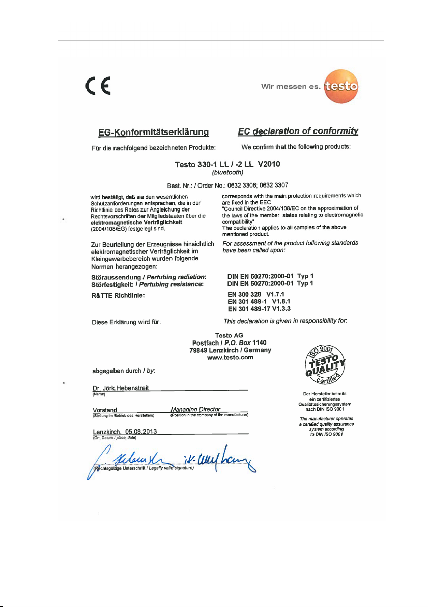
3.2.3. Declaration of Conformity
3 Specifications
15
3 Specifications
16

Pos: 28 /TD/Leistungsbeschreibung/Technische Dat en/testo 330 Technisc he Daten/Messbereic he_Genauigkeiten testo330 @ 6\mod_12786728 96705_79.docx @ 65100 @ 33 @ 1
3.2.4. Measuring ranges and resolution
Parameter Measuring range Resolution
O2 0...21 Vol.% 0.1 vol.%
CO 0...4000 ppm 1 ppm
CO, H2-comp.
COlow 0...500 ppm 0.1ppm
AmbCO
through flue gas
probe
AmbCO with
probe 0632 3331
NO 0...3000 ppm 1 ppm
NOlow 0...300 ppm 0.1 ppm
Draught -9.99...40 hPa 0.01 hPa
∆P 0...300 hPa 0.1 hPa
Temperature -40...1200 °C 0.1°C (-40.0...999.9 °C)
Efficiency net 0...120 % 0.1 %
Flue gas loss 0...99.9 % 0.1 %
AmbCO2 with
probe 0632 1240
Gas leak testing
with probe
0632 3330
1
0...8000 ppm 1 ppm
0...2000 ppm 1 ppm
0...500 ppm 1 ppm
0...1 vol.
0...10000 ppm
0...10000 ppm
CH4 / C3H8
1°C (rest of range)
-
-
3 Specifications
3.2.5. Accuracy and response time
Parameter Accuracy
O2 ±0.2 vol.% < 20s (t90)
1
above the sensor protection threshold: Resolution 1 ppm (up to max.
30,000 ppm)
17
Response
time

3 Specifications
Parameter Accuracy
CO ±20 ppm (0...400 ppm)
±5% of mv (401...2000 ppm)
±10% of mv (2001...4000 ppm)
CO, H2-comp.
±10 ppm or ±10 % of mv
(0...200 ppm)
±20 ppm or ±5 % of mv
(201...2000 ppm)
±10% of mv (2001...8000 ppm)
only testo 330-2:
8000...30000 ppm
(automatic dilution)
COlow ±2 ppm (0…39.9 ppm)
±5 % of mv (rest of range)
AmbCO through
flue gas probe
AmbCO with
0632 3331
±10 ppm (0...100 ppm)
±10 % of mv (101….2000 ppm)
±5 ppm (0...100 ppm)
3
±5 % of mv ( >101 ppm)
NO ±2 ppm (0…39,9 ppm)
±5 % of mv (40….2000 ppm)
±10 % of mv (2001...3000 ppm)
NOlow
±2 ppm (0…39,9 ppm)
±5% of mv (rest of range)
Draught4
±0.02 ppm or ±5% of mv
(-0.50...0.60 hPa)
± 0.03 hPa (0.61...3.00 hPa)
±1.5 % of mv (3.01...40.00 hPa)
Response
time
< 60s (t90)
2
2
< 60s (t90)
< 40s (t90)
< 35s (t90)
approx. 35s
(t90)
< 30s (t90)
< 30s (t90)
2
-
2
higher value is valid
3
at 10...30 °C, outside this range additionally ±0.2 % of mv / °C
4
with fine draught measurement option: Measuring range 0...100,
0Pa, resolution 0.1Pa
18

3 Specifications
Parameter Accuracy
∆P ± 0.5 hPa (0.0...50.0 hPa)
±1 % of mv (50.1...100.0 hPa)
±1.5 % of mv (rest of range)
Temperature ± 0.5 °C (0.0...100.0 °C)
±0.5 % of mv (rest of range)
Efficiency - Flue gas loss - AmbCO2,
through
0632 1240
±75 ppm + 3 % of mv
(0...5000 ppm)
±150 ppm + 5 % of mv
(5001...10000 ppm)
Gas leak testing
- < 2s (t90)
with 0632 3330
Pos: 29 /TD/Leistungsbeschreibung/Technische Dat en/testo 330 Technisc he Daten/weitere Gerä tedaten testo 330 @ 6\mod_12 78676889881_79.doc x @ 65132 @ 35 @ 1
3.2.6. Other instrument data
Flue gas analyser
Characteristic Values
Storage / and
-20...50 °C
transport
temperature
Operating
-5...45 °C
temperature
Ambient humidity 0…90 % rH, not condensing
Power supply
Battery: 3.7 V / 2.6 Ah
Mains unit: 6 V/1.2 A
Protection class IP40
Weight 600 g (excluding battery)
Dimensions 270 x 90 x 65 mm
Memory 500,000 readings
Display Graphic colour display, 240 x 320 pixels
Flue gas
max. 50 mbar
overpressure
Negative pressure max. 80 mbar
Response
time
-
probe
dependent
approx. 35s
(t90)
19

4 Product description
Characteristic Values
Gas leak testing
probe
Storage
temperature battery
Battery charge time approx. 5-6 h
Battery operation
time
Bluetooth® (option) Range < 10 m
Warranty Measuring instrument: 48 months
Pos: 30 /TD/Überschriften/4. Produktbeschreibung @ 0\mod_117377484667 9_79.docx @ 310 @ 1 @ 1
4 Product description
Pos: 31 /TD/Produktbeschreibung/Übersicht/t esto 3xx/testo 330/te sto 330 Beispiel Liefer umfang 0516 3300 @ 15\mod_1386 080504763_79.doc x @ 179198 @ 233 @ 1
visual indication (LED)
audible indication by buzzer
±0...35 °C
6h (pump on, 20 °C ambient temperature)
LL-sensors O2, CO: 48 months
NOlow sensor: 12 months
Other sensors: 24 months
Flue gas probe: 48 months
Thermocouple: 12 months
Battery: 12 months
Further warranty terms: see website
www.testo.com/warranty
4.1. Case 0516 3300 (accessory)
Recommended for stowing away the measuring instrument and
accessories (example)
20

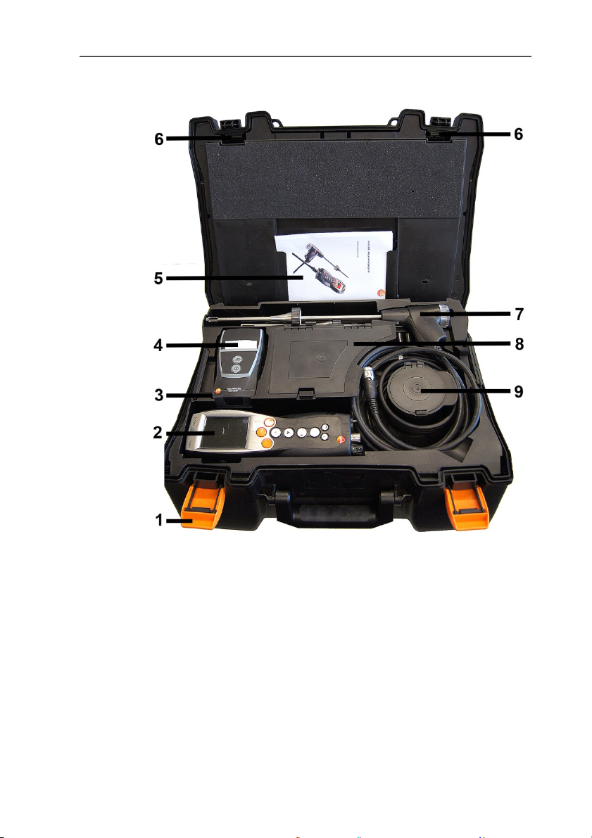
4.1.1. Bottom level view
4 Product description
1 Sealing clip
2 testo 330-1 /-2 LL flue gas analyzer
3 Repository for printer accessories
• Spare batteries for IRDA printer
• 1 roll of spare thermal paper (0554 0568)
4 Repository for printer
• IRDA printer (0554 0549)
• Bluetooth
®
/IRDA printer (0554 0620)
5. Instruction manual
6 Lock
7 Probes
• Flue gas probe (e.g. 0600 9741)
• Pitot tube for heating check (0635 2050)
8 Large storage compartment
21
4 Product description
• Mains unit for testo 330-1 /-2 LL (0554 1096)
• Differential temperature set (0554 1208)
• Spare dirt filter (0554 0040)
9 Round storage compartment
• Hose connection set with pressure adapter (0554 1203)
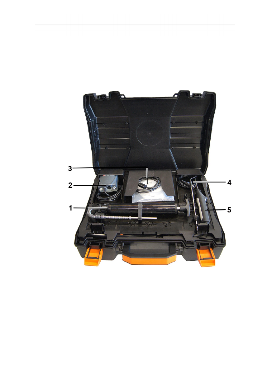
4.1.2. Top level view
22
1 Soot pump set (0554 0307)
2 Storage compartment
• Fine pressure probe (0638 0330)
3 Storage compartment
• Capillary hose set for fine pressure probe (0554 1215)
• Connecting cable for surface probe (0430 1215)
4 Combustion air temperature probe (0600 9787)
5. Surface temperature probe Type K (0604 0994)
Pos: 32 /TD/Produktbeschreibung/Übersicht/t esto 3xx/testo 330/te sto 330 Beispiel Liefer umfang 0516 3301 @ 15\mod_1386 851266100_79.doc x @ 179983 @ 2333 @ 1
4.2. Case 0516 3301 (accessory)
Recommended for stowing away the measuring instrument and
accessories (example)
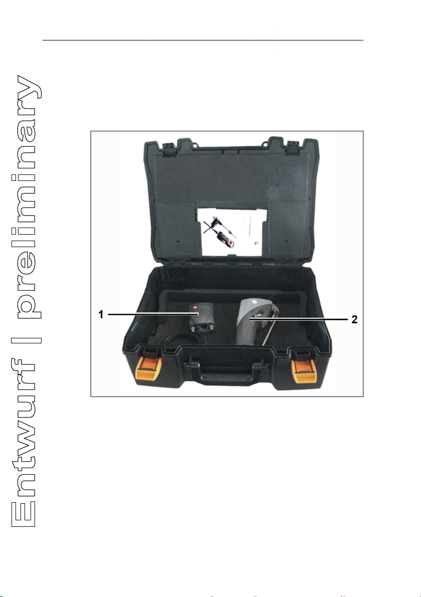
4.2.1. Bottom level view
4 Product description
1 Fine pressure probe (0638 0330)
2 testo 308 smoke tester (0632 0308)
23
4 Product description
4.2.2. Middle level view
24
1 Sealing clip
2 testo 330-1 /-2 LL flue gas analyzer
3 Repository for printer accessories
• Spare batteries for IRDA printer
• 1 roll of spare thermal paper (0554 0568)
4 Repository for printer
• IRDA printer (0554 0549)
• Bluetooth
®
/IRDA printer (0554 0620)
5. Instruction manual
6 Lock
7 Probes
• Flue gas probe (e.g. 0600 9741)
• Pitot tube for heating check (0635 2050)
8 Large storage compartment
• Mains unit for testo 330-1 /-2 LL (0554 1096)
• Differential temperature set (0554 1208)
• Spare dirt filter (0554 0040)
9 Round storage compartment
• Hose connection set with pressure adapter (0554 1203)
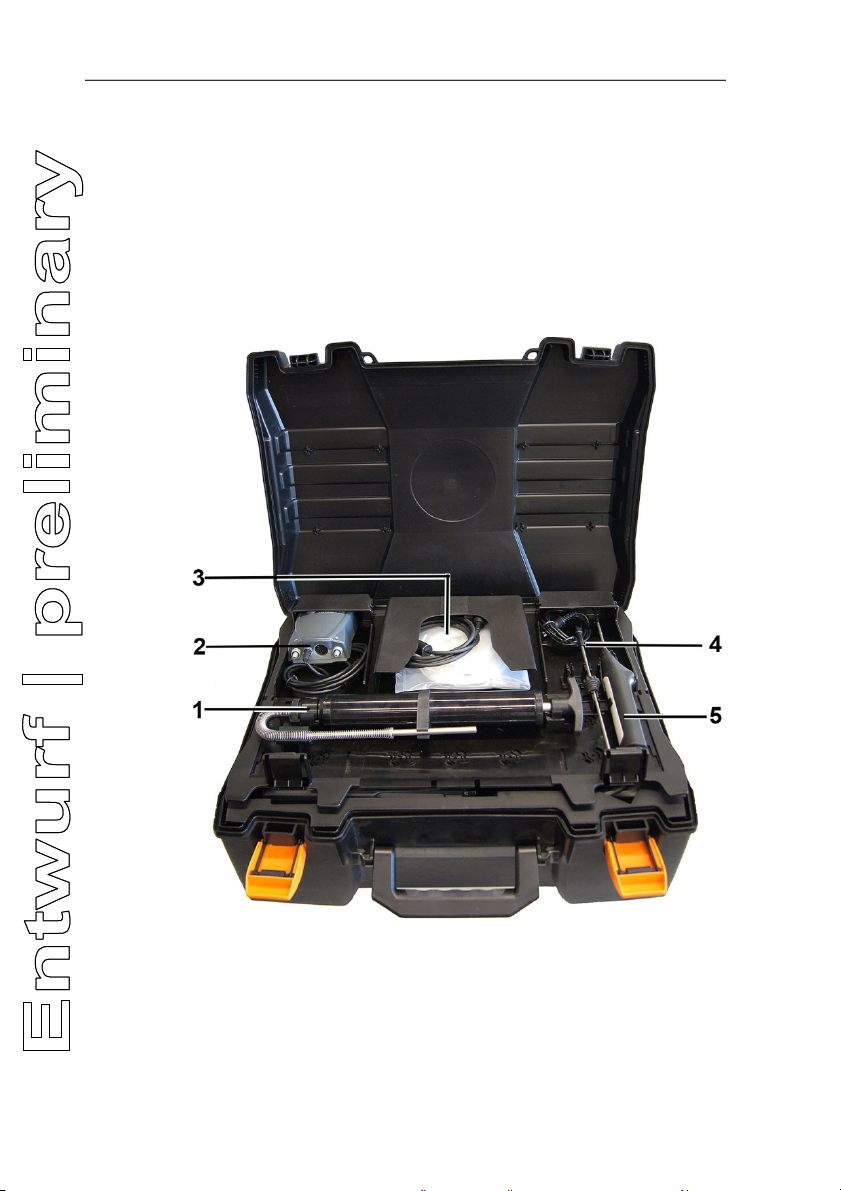
4.2.3. Top level view
4 Product description
1 Soot pump set (0554 0307)
2 Storage compartment
• Fine pressure probe (0638 0330)
3 Storage compartment
• Capillary hose set for fine pressure probe (0554 1215)
• Connecting cable for surface probe (0430 1215)
25
 Loading...