

Page 1
5 Commonwealth Ave
Woburn, MA 01801
Phone 781-665-1400
Toll Free 1-800-517-8431
Visit us at www.TestEquipmentDepot.com
testo 883 - thermal imager
Instruction manual
Page 2

Page 3

Contents
Contents
1 About this document ........................................................................... 7
2 Safety and disposal .............................................................................. 7
3 Product-specific approvals ................................................................. 8
4 Product-specific information............................................................... 8
5 Support ................................................................................................. 8
6 Scope of delivery .................................................................................. 8
7 Product description ............................................................................. 9
7.1 Use ..................................................................................................................... 9
7.1 Instrument / operating elements overview ........................................................... 9
7.1 Displays overview ............................................................................................. 11
7.2 Power supply .................................................................................................... 12
8 Commissioning .................................................................................. 13
8.1 Touchscreen operating concept ........................................................................ 13
8.2 Operation via joystick ........................................................................................ 13
8.3 Rechargeable battery ....................................................................................... 14
8.4 Switching the instrument on and off .................................................................. 16
8.5 Getting to know the menu ................................................................................. 17
8.6 Quick select button ........................................................................................... 17
8.7 Changing the lens ............................................................................................. 20
8.7.1 Removing the lens ................................................................................................... 20
8.7.2 Attaching a new lens ................................................................................................ 21
9 WLAN connection – using the App ................................................... 23
9.1 Activating/disabling the connection ................................................................... 23
9.2 Using the App ................................................................................................... 24
9.2.1 Establishing a connection ......................................................................................... 24
9.2.2 Select display ........................................................................................................... 25
10 Bluetooth® connection ....................................................................... 26
11 Performing the measurement............................................................ 29
11.1 Saving an image with preview........................................................................... 29
11.2 Setting measuring functions .............................................................................. 30
11.2.1 Pixel mark ................................................................................................................ 32
11.2.2 New Min/Max on area .............................................................................................. 33
11.2.3 Differential temperature ............................................................................................ 34
11.2.4 External values ........................................................................................................ 35
11.2.5 SiteRecognition ........................................................................................................ 36
11.2.6 IFOV ........................................................................................................................ 37
11.2.7 Isotherm ................................................................................................................... 38
11.2.8 Alarm ....................................................................................................................... 39
Page 4

Contents
11.2.9 Zoom ....................................................................................................................... 41
11.3 Image gallery .................................................................................................... 42
11.4 Scale ................................................................................................................ 44
11.5 Emissivity ......................................................................................................... 47
11.5.1 Selecting the emissivity ........................................................................................... 49
11.5.2 Customizing the emissivity ....................................................................................... 50
11.5.3 Setting RTC ............................................................................................................. 50
11.5.4 Setting ε-Assist ........................................................................................................ 51
11.6 Palette .............................................................................................................. 52
11.7 Image type ....................................................................................................... 53
11.8 SiteRecognition ................................................................................................ 54
11.9 Voice annotation ............................................................................................... 55
11.10 Configuration .................................................................................................... 56
11.10.1 Settings ................................................................................................................... 56
11.10.2 SuperResolution ...................................................................................................... 63
11.10.3 Save JPEG .............................................................................................................. 63
11.10.4 Connectivity ............................................................................................................. 64
11.10.5 Protective glass ....................................................................................................... 65
11.10.6 Lens ........................................................................................................................ 66
11.10.7 Quick select button .................................................................................................. 68
11.10.8 Ambient conditions .................................................................................................. 68
11.10.9 Color selection ......................................................................................................... 70
11.10.10 Info .......................................................................................................................... 71
11.10.11 Certificates .............................................................................................................. 72
11.10.12 Fullscreen mode ...................................................................................................... 74
11.10.13 Reset options .......................................................................................................... 75
11.10.13.1 Reset counter .......................................................................................................................... 75
11.10.13.2 Factory settings ....................................................................................................................... 77
11.10.13.3 Formatting ............................................................................................................................... 78
12 Maintenance ....................................................................................... 80
12.1 Charging the rechargeable battery.................................................................... 80
12.2 Changing the rechargeable battery ................................................................... 80
12.3 Cleaning the instrument .................................................................................... 82
12.4 Firmware update .............................................................................................. 83
12.4.1 Performing an update using IRSoft .......................................................................... 83
12.4.1.1 Preparing the camera ............................................................................................................. 83
12.4.1.2 Performing an update ............................................................................................................. 83
12.4.2 Performing an update with the camera ..................................................................... 84
12.4.2.1 Preparing the camera ............................................................................................................. 84
12.4.2.2 Performing an update ............................................................................................................. 84
Page 5

Contents
13 Technical data .................................................................................... 86
13.1 Optical data ...................................................................................................... 86
13.2 Image presentation ........................................................................................... 86
13.3 Data interfaces ................................................................................................. 87
13.4 Measuring functions.......................................................................................... 87
13.5 Imager features ................................................................................................ 88
13.6 Image storage................................................................................................... 89
13.7 Audio functions ................................................................................................. 89
13.8 Power supply .................................................................................................... 89
13.9 Ambient conditions ........................................................................................... 89
13.10 Physical features .............................................................................................. 90
13.11 Standards, tests ................................................................................................ 90
14 Questions and answers ..................................................................... 91
15 Accessories ........................................................................................ 91
Page 6

Page 7
1 About this document
Note: basic or further information.
Action: several steps, the sequence must be followed.
• …
List
Action: one step or optional step.
Result of an action.
✓ …
Requirement
Position numbers for the clarification of the relationship
Elements of the instrument, the instrument display or the
program interface.
Control keys of the instrument or buttons of the program
interface.
... | ...
Functions/paths within a menu.
1 About this document
• The instruction manual is an integral part of the instrument.
• Keep this documentation to hand so that you can refer to it when necessary.
• Always use the complete original instruction manual.
• Please read this instruction manual through carefully and familiarize yourself
with the product before putting it to use.
• Hand this instruction manual on to any subsequent users of the product.
• Pay particular attention to the safety instructions and warning advice in order
to prevent injury and damage to the product.
• Familiarity with a PC as well as the Microsoft® products is assumed in this
documentation.
Symbols and writing standards
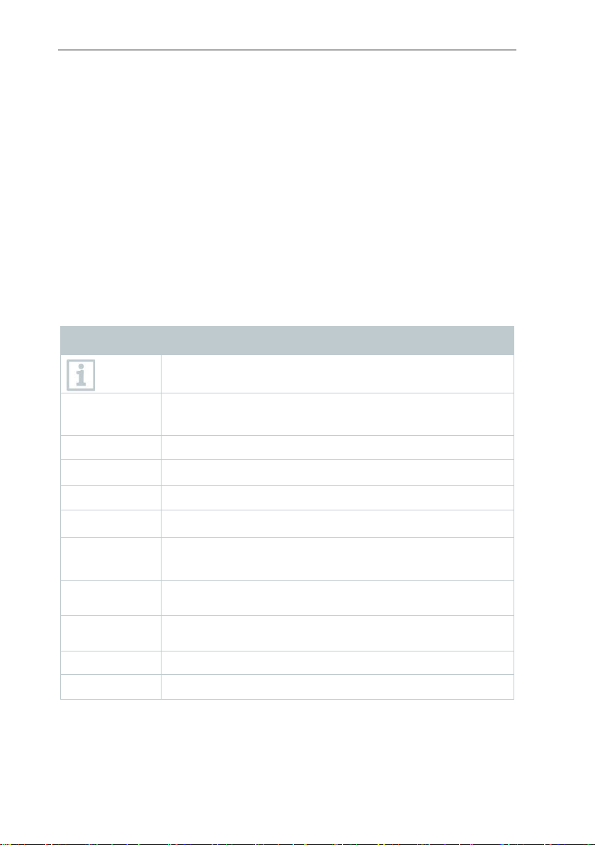
Display Explanation
1. ...
2. ...
> ...
- ...
1...
2...
between text and picture.
Menu
[OK]
“...” Example entries
2 Safety and disposal
Take the testo information document into account (accompanies the product).
7
Page 8

3 Product-specific approvals
ATTENTION
testo 883
testo 883
USB-C cable
USB-C cable
Mains unit (USB)
Mains unit (USB)
Rechargeable battery
Rechargeable battery
Technical documentation
Technical documentation
Calibration protocol
Calibration protocol
Carrying strap
Carrying strap
Bluetooth® headset (country-specific
radio authorization)
Bluetooth® headset (country-specific
radio authorization)
Spare rechargeable battery
Telephoto lens
Charging cradle (with cable)
3 Product-specific approvals
Please find the current country approvals in the enclosed Approvals and
Certifications document.
4 Product-specific information
Damage to the detector!
During operation, this instrument must not be pointed at the sun or other
intensive sources of radiation (e.g. objects with temperatures exceeding
650 °C). This can cause serious damage to the detector. The manufacturer
does not provide any warranty for any such damage to the microbolometer
detector.
6 Scope of delivery
testo 883
Individual unit in a case
8
testo 883
Kit in a case
Page 9
7 Product description
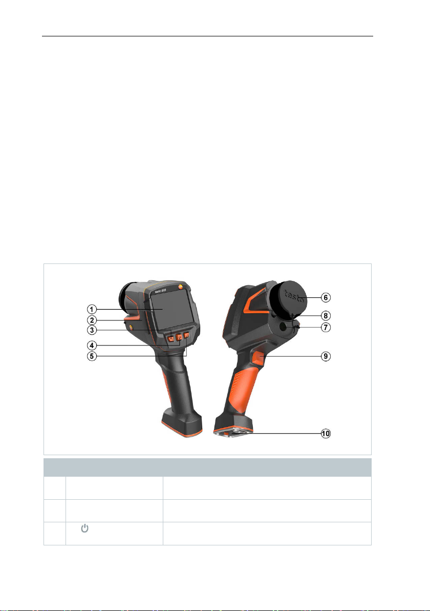
1
Touchscreen monitor
Displays infrared and real images, menus and
functions
2
Interface terminal
Contains USB-C port for power supply and
connection to the computer
3
- key
- Esc key
- Switch camera on and off
- Cancel action
7 Product description
7.1 Use
The testo 883 is a handy, robust thermal imager. You can use it to undertake
the non-contact measurement and display of surface temperature distribution.
Areas of application
• Preventive maintenance / servicing: Electrical and mechanical inspection of
systems and machines
• Building inspection: Energy efficiency rating of buildings (heating, ventilation,
air-conditioning trade, building engineers, engineering firms, experts)
• Production monitoring / quality assurance: monitoring of production
processes
7.1 Instrument / operating elements
overview
Element Function
9
Page 10
7 Product description
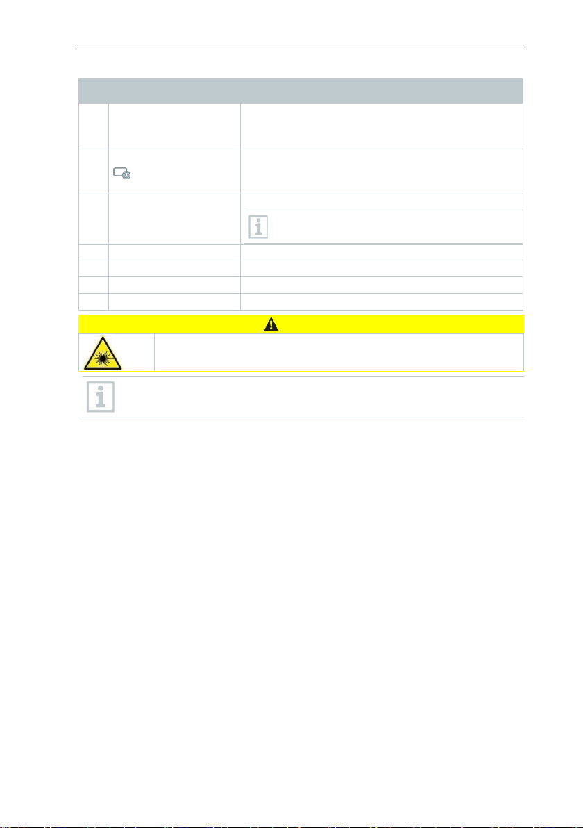
4
- OK key
- Joystick
- Open menu, select function, confirm setting
select colour palette
5
Quick select button
Opens the function assigned to the quick select
displayed bottom right
6
Infrared camera lens;
Takes infrared images; protects the lens
7
Digital camera
Takes real images
8
Laser
Marking of the measuring point
9
Trigger
Saves the displayed image
10
Battery compartment
Contains the rechargeable battery
CAUTION
Laser radiation! Class 2 laser
Element Function
- Navigate within the menu, highlight function,
button; the icon for the selected function is
protective cap
- Do not look into the laser beam
Laser can be activated with the Remote function, also via smartphone
or tablet.
Lens is interchangeable
10
Page 11
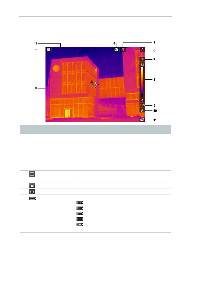
7.1 Displays overview
1
Status bar
The following values are displayed in the status
2 Open menu.
3
Image display
IR image or real image display
4 Protective glass enabled
5 Headset connected
6 Battery capacity / charge status:
: Mains operation, battery is charging.
7
°C or °F
Unit set for reading and scale displays.
Element Function
bar depending on the setting:
• Humidity and ambient temperature
• Current, voltage, solar radiation and power
• Differential temperature
• Zoom level (2 x, 4 x)
7 Product description
: Battery operation, capacity 50-75%
: Battery operation, capacity 25-50%
: Battery operation, capacity 10-25%
: Battery operation, capacity 0-10%
11
Page 12
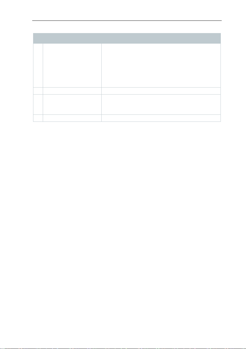
7 Product description
8
Scale
- Temperature unit
manual scale adjustment).
9
E ...
Set emissivity.
10
A, M or S
A - automatic scale adjustment
S - ScaleAssist is enabled
11
Quick select button
The set function is displayed.
Element Function
- White characters: temperature margin of the
image displayed, showing the
minimum/maximum reading (with automatic
scale adjustment) or the set
minimum/maximum display value (with
M - manual scale adjustment
7.2 Power supply
The power is supplied to the instrument via a replaceable rechargeable battery
or the mains unit provided (battery must be inserted).
With an attached mains unit, power is supplied automatically via the mains unit
and the rechargeable battery is charged (only at ambient temperatures from 0 to
35 °C).
It is also possible to charge the battery using a charging station (accessory).
To maintain system data during a power interruption (e.g. when changing the
battery), the data is stored temporarily.
12
Page 13
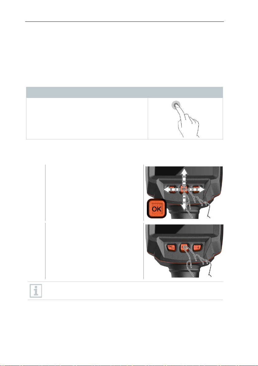
8 Commissioning
Tapping
1
Move joystick up/down or to the
2
Press joystick [OK] to confirm the
8 Commissioning
8.1 Touchscreen operating concept
Familiarize yourself with the touchscreen operating concept before you use the
measuring instrument.
Actions are carried out by:
Description
To open applications, select menu icons or
press buttons on the display, in each case tap
these with your finger.
8.2 Operation via joystick
Move the joystick up/down and right/left to select the individual menus.
left/right.
selection.
Please read the testo 883 1st steps commissioning instructions
supplied (0972 8830).
13
Page 14
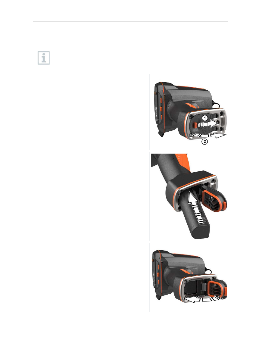
8 Commissioning
1
Pull back the unlocking button to
2
Push the battery all the way into the
3
Close the battery compartment cover
The thermal imager starts automatically.
8.3 Rechargeable battery
The cam
battery is supplied separately and must first be unpacked and inserted
in the camera.
rechargeable battery slot until this is
flush with the bottom of the handle.
era is delivered without a battery inserted. The rechargeable
open the battery compartment cover
on the bottom of the handle.
and secure with the unlocking button.
14
Page 15
8 Commissioning
1
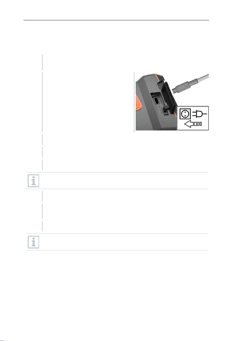
Connect the country-specific adapter required for the existing mains to
the mains unit.
2
Open the cover on the left side of the
3
Connect the mains unit to the USB-C jack.
4
Connect the USB cable to the USB mains unit.
Battery charging starts.
5
Fully charge the battery, then disconnect the instrument from the
mains unit.
After initial charging of the battery, the imager is ready for use.
Initial charging of the battery
The imager is supplied with a partially charged battery. Charge the battery fully
before using it for the first time.
thermal imager.
The thermal imager starts automatically.
The battery can be recharged with the imager switched on or off. This
has no effect on the time required to charge the battery.
A desktop charging station (order no. 0554 8801) can also be used to
charge the battery.
Rechargeable battery care
• Do not fully exhaust rechargeable batteries.
• Store rechargeable batteries only when charged and at low temperatures,
but not below 0 °C (best storage conditions are 50-80% charge, at an
ambient temperature of 10-20 °C, recharge completely before using again).
• For longer breaks, you should discharge and recharge the batteries every 34 months. Trickle charging should not exceed 2 days.
15
Page 16
8 Commissioning
1
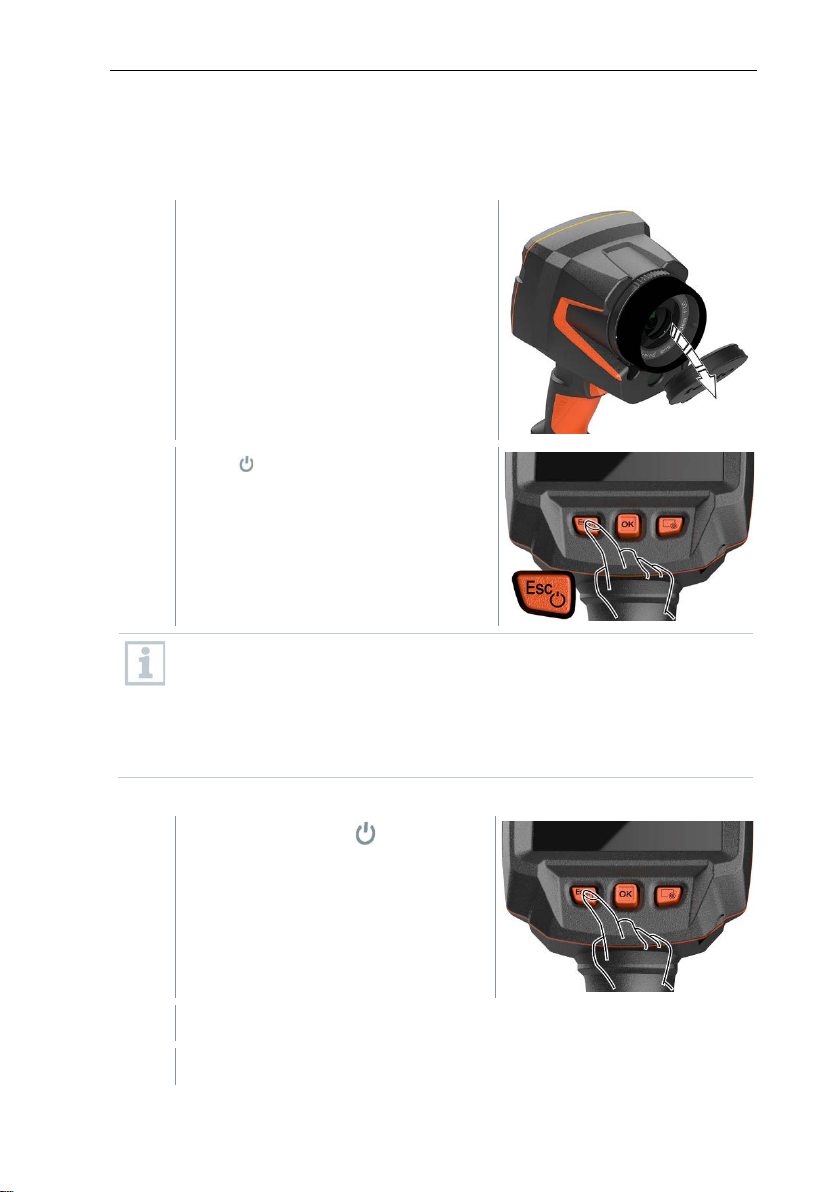
Remove protective cap from the lens.
2
To ensure measuring accuracy, the camera performs automatic zeroing
1
8.4 Switching the instrument on and off
Switching on the camera
Press .
The camera starts.
The start screen appears on the
display.
approx. every 60 s. A “click” is heard when this happens. The image
freezes briefly when this occurs. Zeroing is carried out more frequently
during the camera warm-up period (takes approx. 90 seconds).
During the warm-up period no measuring accuracy is guaranteed. The
image can already be used for indication purposes and saved.
Switching off the camera
Press and hold down until the
progress bar on the display is
complete.
16
The display goes off.
The camera is switched off.
Page 17
1
2
Select the submenu (joystick or touchscreen).
3
To exit the submenu again:
bar and confirm with OK.
8.5 Getting to know the menu
testo 883 can also be operated via the monitor’s touchscreen feature.
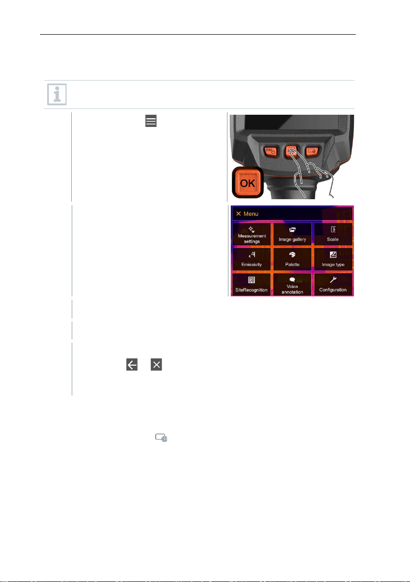
Press OK or tap to open the
menu.
Menu opens.
8 Commissioning
Submenu opens.
o Tap or or
o Move the joystick to the left or move the joystick to the menu
8.6 Quick select button
The quick select button is another navigation option that allows you to access
certain functions by pressing or tapping the icon of the quick select button on
the screen.
17
Page 18
8 Commissioning
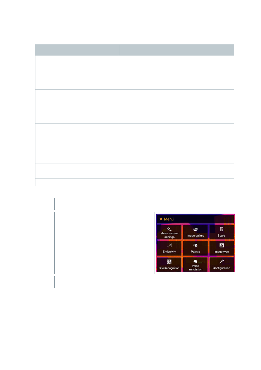
Image gallery
Opens an overview of saved images.
Scale
infrared)
Set scale limits.
Emissivity
infrared)
Set emissivity (E) and reflected temperature
Palette
Toggles the palette selection.
Adjustment
infrared)
Carries out manual zeroing.
Image type
Alternately switches the image display
between infrared and real image.
Laser
Activates the laser pointer.
Zoom
Enlarges the image section (2 x, 4 x)
SiteRecognition
Site recognition
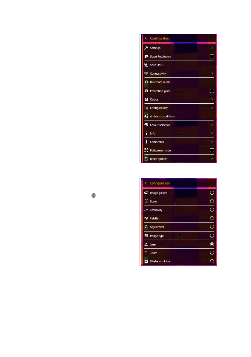
1
Move the joystick to the right.
1.1
Open the Menu.
1.2
Select Configuration (joystick or touchscreen).
Quick select menu items
Menu item Function
(This function is only available if
the Image type is set to
(This function is only available if
the Image type is set to
(This function is only available if
the Image type is set to
Changing assignment
(RTC).
18
Page 19
8 Commissioning
1.3
Select Configure key (joystick or touchscreen).
2
Select the required menu item (joystick or touchscreen).
Configuration opens.
The Configure key selection menu
opens. The activated function is
marked with a dot ( ).
The quick select button is assigned to the selected menu item.
The icon for the selected function is displayed bottom right.
19
Page 20
8 Commissioning
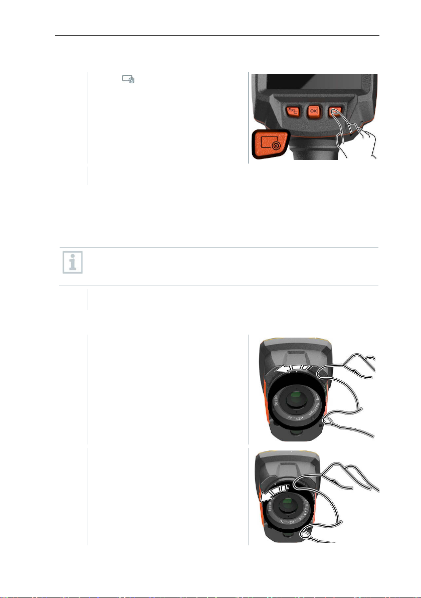
1
Press .
The imager must be placed on a stable surface.
1
Turn the lens fixing ring anti-
2
Turn the lens anti-clockwise as far as
Using the quick select button
The function assigned to the quick select button is carried out.
8.7 Changing the lens
Only lenses that have been adjusted to the respective thermal imager can be
used. The serial number on the lens must match the serial number displayed in
the imager, .
The lens can be changed while the imager is running. The imager
automatically detects which lens is fitted and makes the information
8.7.1 Removing the lens
readily available in the menu.
clockwise as far as it will go.
it will go.
20
Page 21
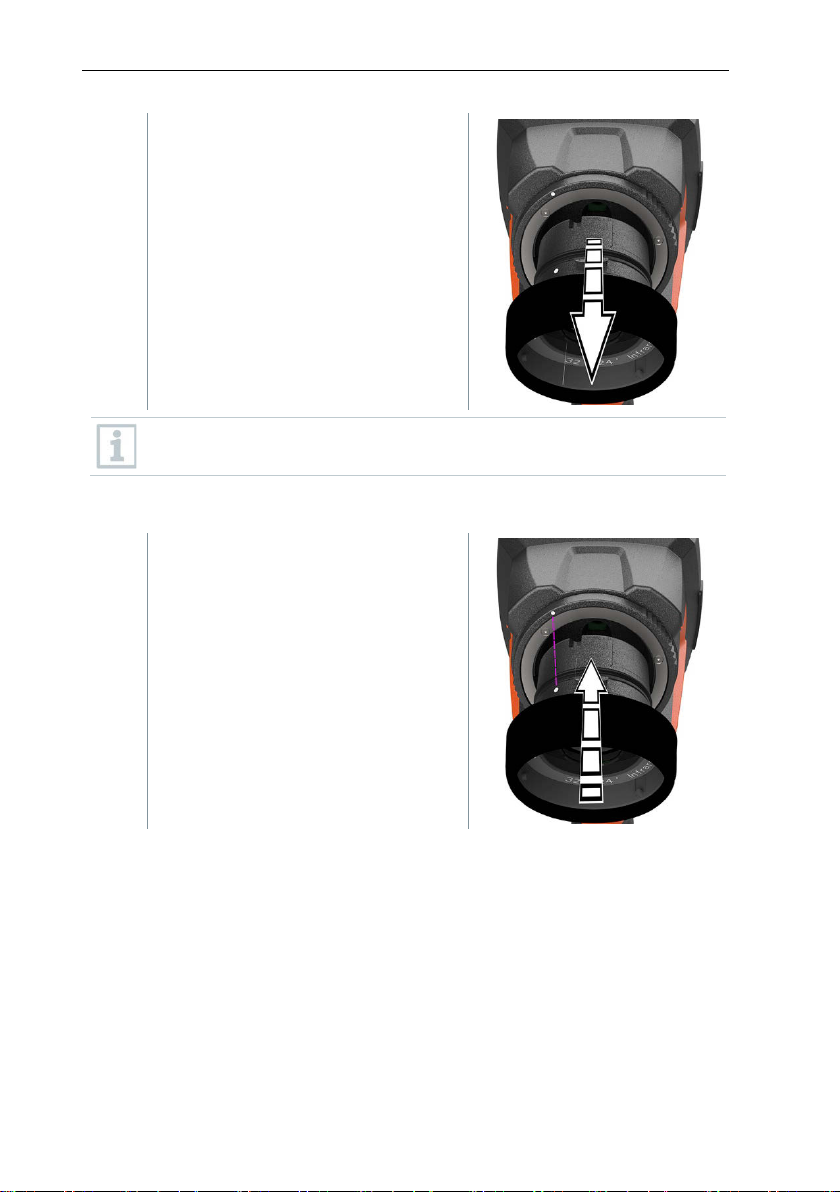
3
Remove lens.
1
Attach a new lens.
Always store unused lenses in the lens box (supplied with the
interchangeable lens).
8.7.2 Attaching a new lens
8 Commissioning
21
Page 22
8 Commissioning
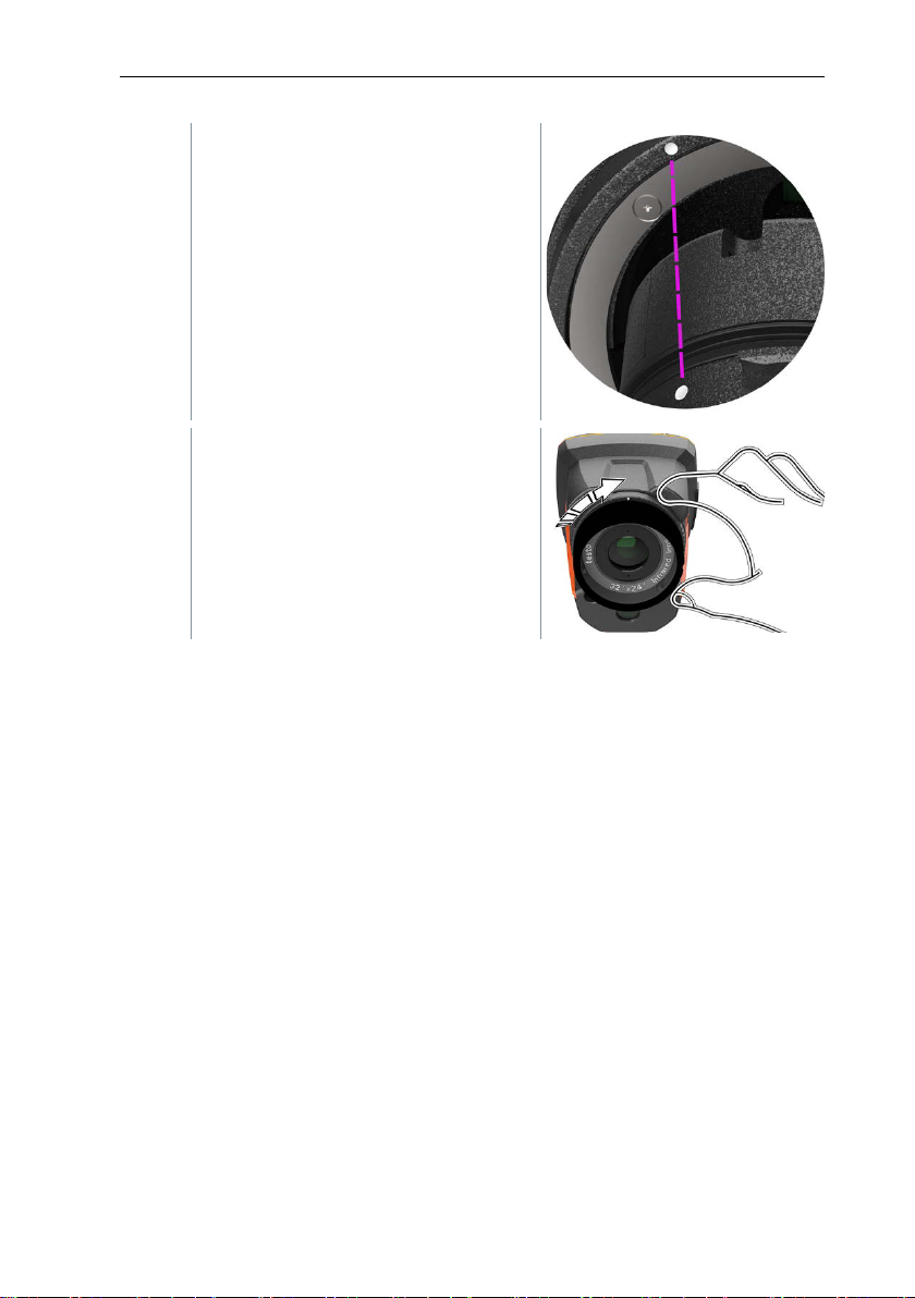
2
Align the markings on the lens and
3
Turn the lens fixing ring clockwise as
handle.
far as it will go.
22
Page 23
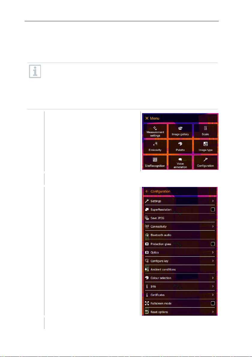
9 WLAN connection – using the App
1
Open the Menu.
2
Select Configuration (joystick or touchscreen).
3
Select Connectivity (joystick or touchscreen).
9 WLAN connection – using the App
^
9.1 Activating/disabling the connection
To connect via WLAN, you need a tablet or smartphone with the testo
Thermography App already installed on it.
You can get the App from the App Store for iOS devices or from the
Play Store for Android devices.
Compatibility:
Requires iOS 8.3 or later / Android 4.3 or later.
Configuration opens.
23
Page 24
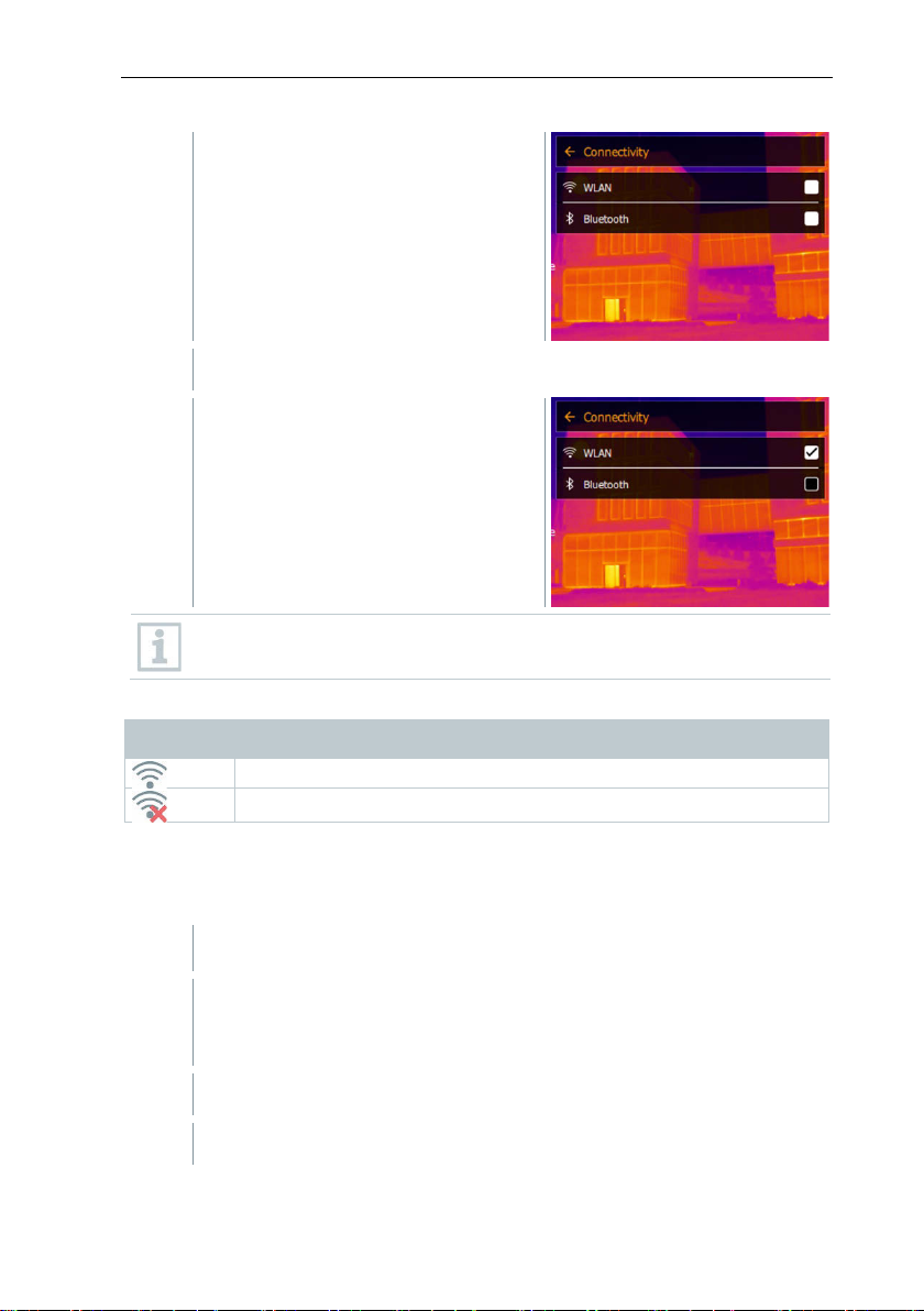
9 WLAN connection – using the App
4
Select WLAN (joystick or touchscreen).
App is connected
No connection to the App
WLAN is activated in the thermal imager.
1
Smartphone/tablet -> Settings -> WLAN settings -> camera is
2
Select testo 883 in the WLAN settings.
3
Enter password: testo 883
Connectivity opens.
A check mark appears when WLAN is
enabled.
While WLAN is activated, the image gallery cannot be accessed.
Explanation of WLAN icons
Symbol Function
9.2 Using the App
9.2.1 Establishing a connection
shown with serial number (testo 883 (12345678)) and can be
selected.
24
Page 25

The password must be entered once.
4
Press Connect.
The WLAN connection to the thermal imager is established.
1
Selection -> 2nd display.
The WLAN connection to the thermal imager is established.
1
Selection -> Remote.
The WLAN connection to the thermal imager is established.
1
Selection -> Gallery.
The WLAN connection to the thermal imager is established.
9.2.2 Select display
Second display
The display on the thermal imager is shown on your mobile end
device.
Remote
9 WLAN connection – using the App
The display on the thermal imager is shown on your mobile end
device. The thermal imager can be controlled and settings made via
the mobile terminal device.
Gallery
The saved images are displayed and can be managed.
25
Page 26
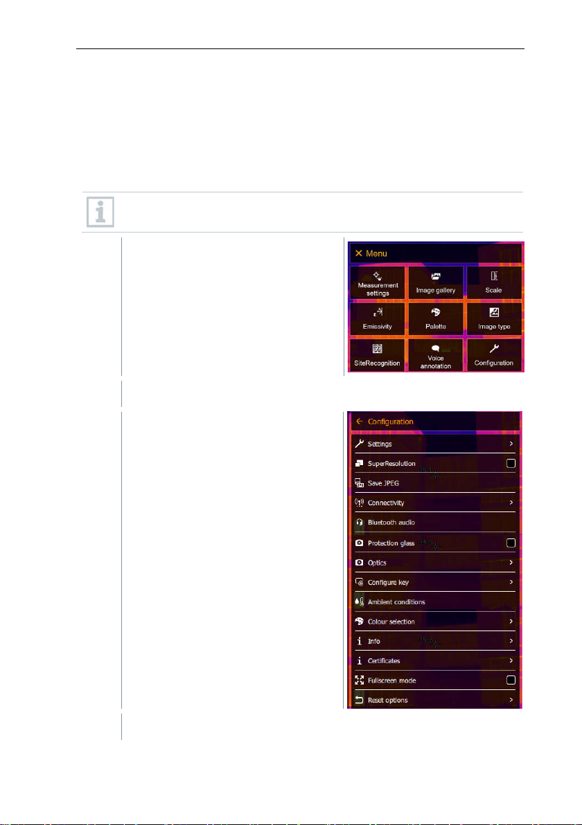
10 Bluetooth® connection
1
Open the Menu.
2
Select Configuration (joystick or touchscreen).
3
Select Connectivity (joystick or touchscreen).
10 Bluetooth® connection
A connection between the thermal imager and the testo 605i humidity probe or
testo 770-3 clamp meter can be established via Bluetooth
Via the Bluetooth radio interface, a link to a Bluetooth headset can be
established for voice recording. Please follow the instruction manual for the
Bluetooth headset.
Bluetooth® 4.0 required.
Configuration opens.
®
.
26
Page 27
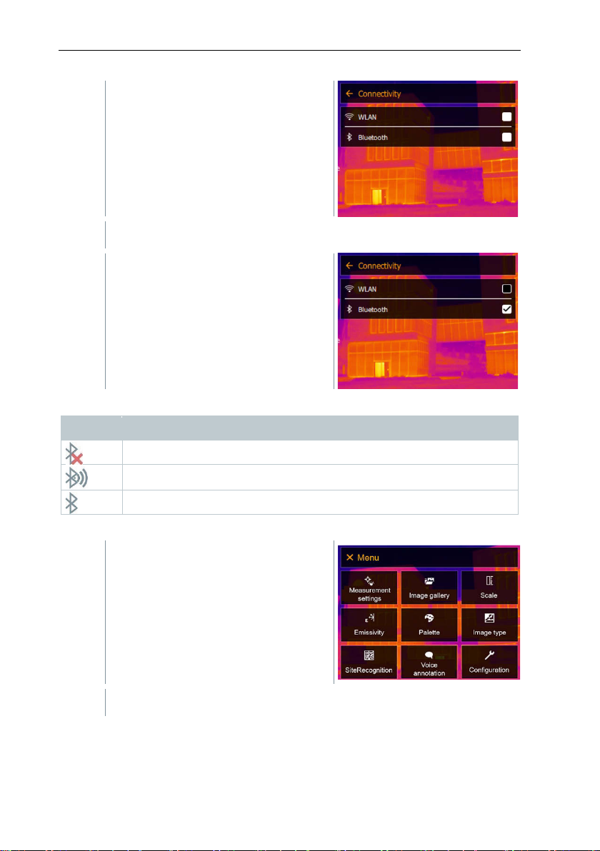
Connectivity opens.
4
Select Bluetooth® (joystick or touchscreen).
No connection to the humidity probe, testo 605i or testo 770-3
Searching for humidity probe.
Humidity probe readings are being transmitted.
1
Open the Menu.
2
Select Measurement settings (joystick or touchscreen).
A check mark appears if Bluetooth® is
enabled.
Explanation of Bluetooth® icons
Symbol Function
10 Bluetooth® connection
When connected to the clamp meter
27
Page 28
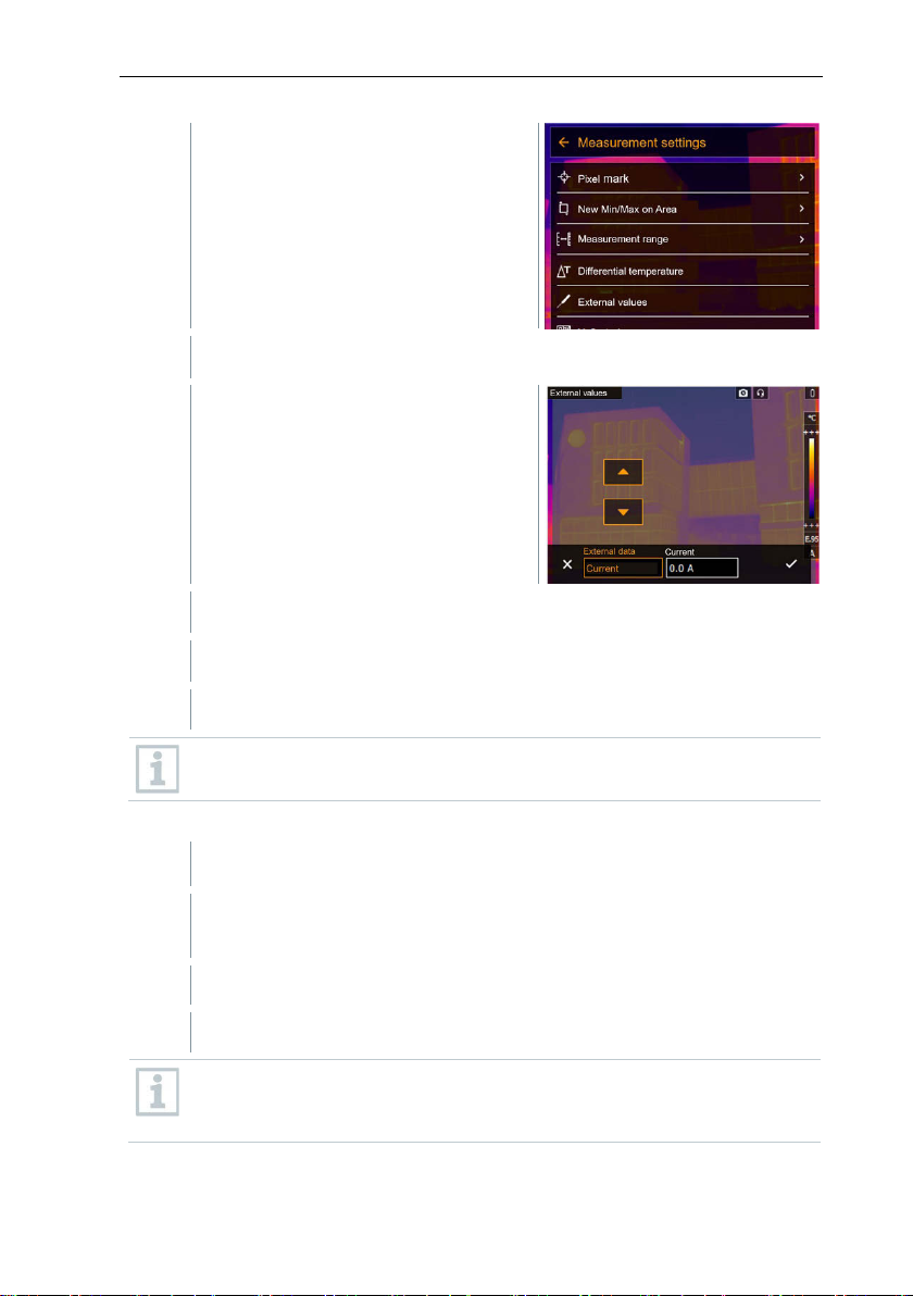
10 Bluetooth® connection
3
Select External values (joystick or touchscreen).
4
Select the required size (joystick or touchscreen).
5
Confirm selection with or exit the menu with X.
Bluetooth® connection is enabled.
In the Measurement -> External values menu, the Humidity
If a WLAN connection is enabled in addition, the Bluetooth data transfer
Measurement settings opens.
External values opens.
Clamp meter readings are displayed in the header.
Readings are only transferred if the current, voltage or power is set on
the clamp meter.
When connected to the humidity probe
measurement function is selected.
The thermal imager switches automatically to humidity measurement.
Humidity probe readings are displayed in the header.
28
is continued. However, it is not possible to establish a new connection
to a humidity probe.
Page 29

11 Performing the measurement
1
Press Trigger.
11 Performing the measurement
The testo 883 can be operated both by joystick and by touchscreen on
the monitor.
ATTENTION
High thermal radiation (e.g. due to sun, fire, furnaces)
Detector may be damaged!
- Do not point the camera at objects with temperatures > 650 °C.
Ideal framework conditions
Building thermography, investigating the building shell:
Considerable temperature difference between inside and out
(ideal: ≥ 15 °C / ≥ 27 °F).
Consistent weather conditions, no intensive sunlight, no precipitation, no
s
trong wind.
To ensure maximum accuracy, the camera requires an adjustment time of
15 minutes
Important camera settings
after it is switched on.
• Emissivity and reflected temperature must be set correctly in order to
precisely determine the temperature. Subsequent adjustment is possible via
the PC software, if required.
• When auto-scaling is activated, the colour scale is continuously adjusted to
the min./max. values of the current measurement image. This means that
the colour assigned to a specific temperature is changing constantly! To be
able to compare multiple images based on the assigned colour, scaling must
be set manually to fixed values, or must be subsequently adjusted to uniform
values using the PC software.
side required
11.1 Saving an image with preview
The image is automatically saved.
Regardless of the image type set, an infrared image is saved with an
attached real image.
29
Page 30
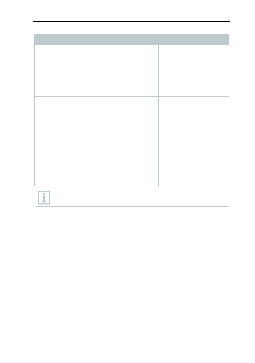
11 Performing the measurement
Action
Description
Result
Trigger operation
Aim at any subject.
The subject aimed at
checking purposes.
Cancel recording
Press
- touch bottom left corner
Live image is displayed.
Recording
Aim at any subject.
Press trigger again.
Live image is displayed.
Recording with
Aim at any subject.
Press trigger again.
Live image is displayed.
1
Open Measurement submenu (joystick or touchscreen).
marked with red crosshairs and the value is displayed.
audio
Press trigger.
- left key or
Press trigger
Select the Audio
commentary menu
Press trigger
In the Voice annotation
menu, select Recording
with audio
Audio commentary is made
with (connected) headset.
For a higher resolution, in the Configuration menu, select the
SiteRecognition submenu.
remains frozen on the
camera display for
Image is not saved.
Image is saved.
Image is saved with audio
commentary.
11.2 Setting measuring functions
The Measurement submenu opens with the measurement
settings:
• Pixel mark:
o New measuring spot: A new measuring point can be
added, moved or removed.
30
- Edit/Remove measurement point…
- Measurement point 1
- Measurement point 2
- …
o Center spot: the temperature measuring point in the
centre of the image is marked with white crosshairs and
the value is displayed.
o Hotspot: the highest temperature measuring point is
Page 31

11 Performing the measurement
o Coldspot: the lowest temperature measuring point is
2
Select the required function (joystick or touchscreen).
marked with blue crosshairs and the value is displayed.
o Show all / Hide all: Show or hide the centre point, hotspot
and coldspot.
• New Min/Max on area:
o Min/Max on area: Area in the centre of the image is
shown. The minimum, maximum, and average values for
the area are displayed.
o Hotspot: the highest temperature measuring point within
• Measurement range: choose between two measuring ranges
• Differential temperature: identifies the difference between two
• External values: in various measuring modes, values can be
• iFOV: the IFOV warner shows what can be measured
• Isotherm: limit values can be set. All readings within the set
• Alarm: Temperatures below or above a limit value are also
• Zoom: enlarges the image section (2x and 4x).
• SiteRecognition: testo SiteRecognition recognizes markers,
the range selection is marked with blue or red crosshairs
and the value is displayed.
o Coldspot: the lowest temperature measuring point within
the range selection is marked with blue or red crosshairs
and the value is displayed.
o Show all / Hide all: Show or hide the selected area.
or temperature ranges.
temperatures.
o Difference between two measuring points
o Difference between measuring point and input value
o Difference between measuring point and value of an
external probe
o Difference between measuring point and the reflected
temperature (RTC)
determined either manually or with a Bluetooth
instrument.
accurately from a specific distance.
limits are displayed uniformly in one colour.
visualized.
the recorded images are assigned to the corresponding
measuring location by the IRSoft PC software and stored in the
database.
®
measuring
31
Page 32
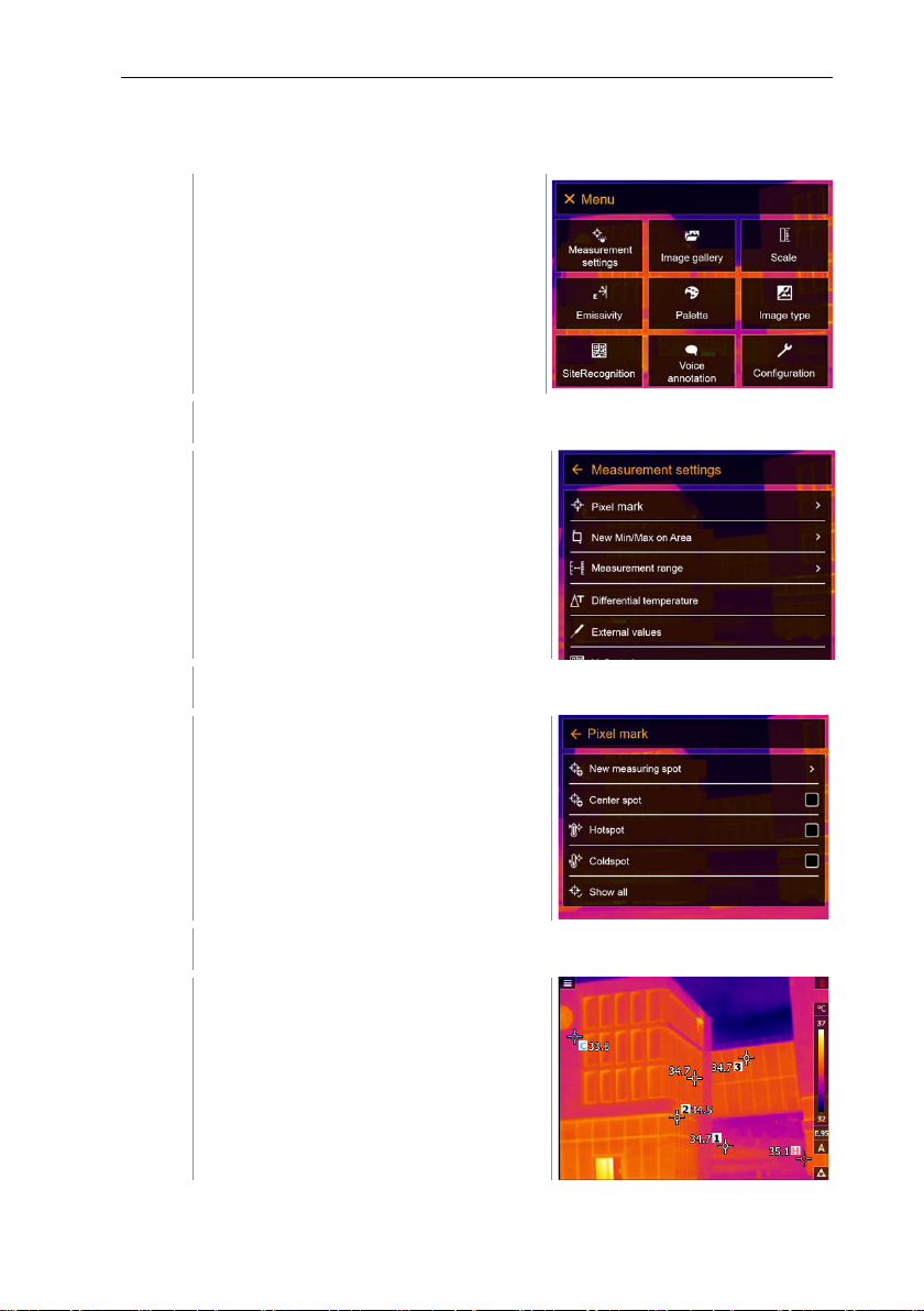
11 Performing the measurement
1
Open the Menu.
2
Select Measurement settings (joystick or touchscreen).
3
Select Pixel mark (joystick or touchscreen).
4
Select Settings (joystick or touchscreen).
11.2.1 Pixel mark
Measurement settings opens.
The Pixel mark submenu opens.
Measurement view is displayed.
32
Page 33
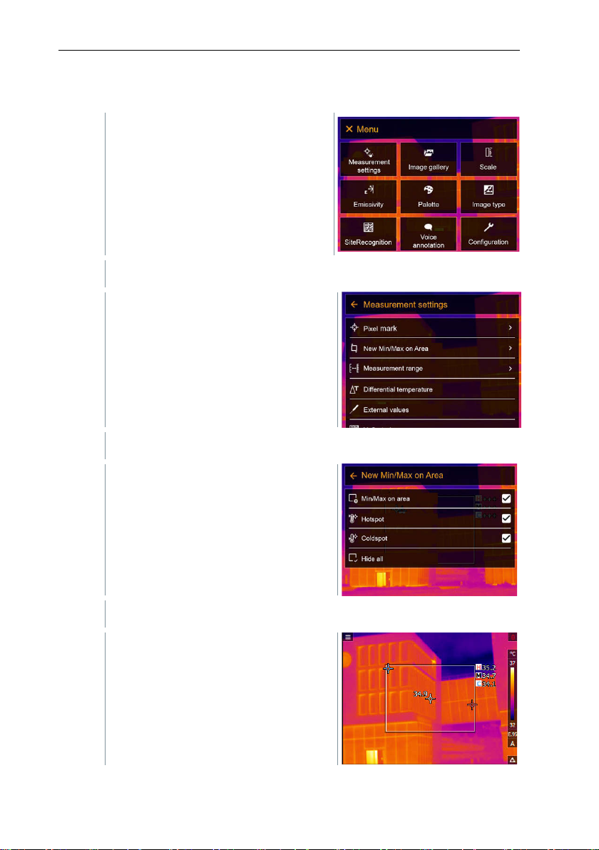
11.2.2 New Min/Max on area
1
Open the Menu.
2
Select Measurement settings (joystick or touchscreen).
3
Select New Min/Max on area (joystick or touchscreen).
4
Select Settings (joystick or touchscreen).
Measurement settings opens.
11 Performing the measurement
New Min/Max on area submenu
opens.
Measurement view is displayed.
33
Page 34
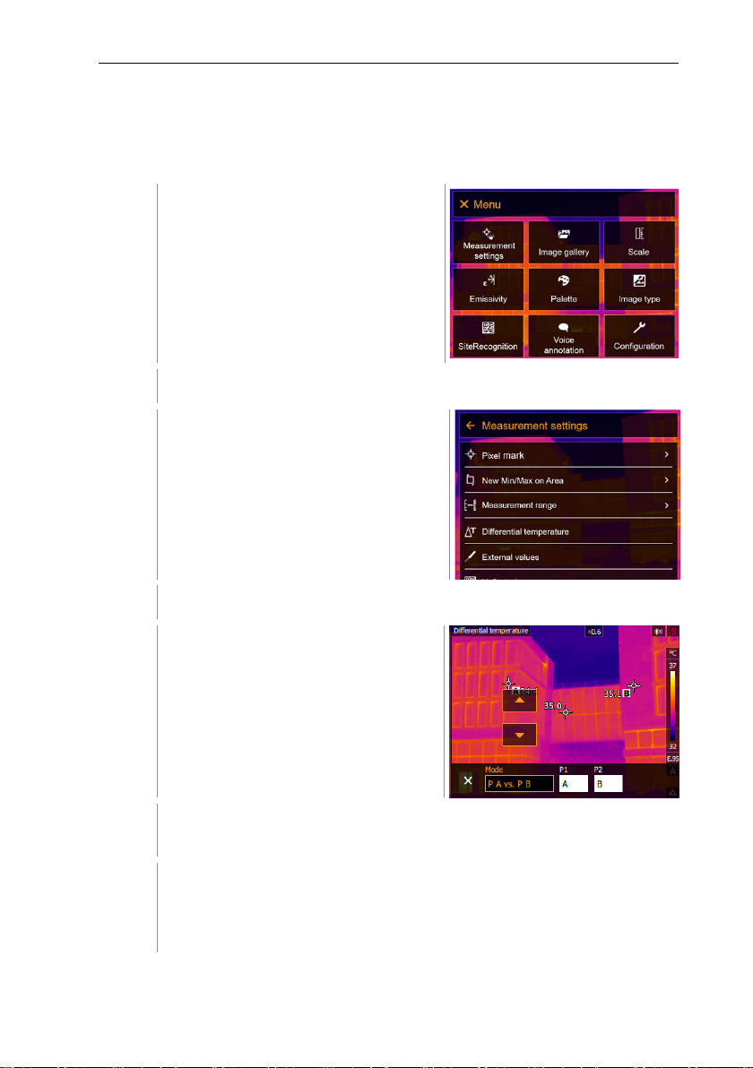
11 Performing the measurement
1
Open the Menu.
2
Select Measurement settings (joystick or touchscreen).
3
Select Differential temperature (joystick or touchscreen).
4
Select the differential temperature to be calculated (joystick or
4.1
PA vs. PB selection:
> move the measuring point to
the live image using the joystick -> press OK.
11.2.3 Differential temperature
Differential temperature enables the temperatures between two measuring
points to be calculated.
Measurement settings opens.
Differential temperature opens.
touchscreen) (PA vs. PB, PA vs. Probe, PA vs. Value, PA vs. RTC).
34
o Move the joystick to the right (or via touchscreen) -> select
measuring point A -> press OK -
Page 35

11 Performing the measurement
o Move the joystick to the right (or via touchscreen) -> select
> move the measuring point to
touchscreen), and confirm with .
4.2
PA vs. Probe selection:
> move the measuring point to
touchscreen), and confirm with .
4.3
PA vs. Value selection:
> move the measuring point to
touchscreen), and confirm with .
4.4
PA vs. RTC selection:
> move the measuring point to
touchscreen), and confirm with .
1
Open the Menu.
2
Select Measurement settings (joystick or touchscreen).
measuring point B -> press OK -
the live image using the joystick -> press OK.
o End measurement: Move the joystick to the right (or via
o Move the joystick to the right (or via touchscreen) -> select
measuring point A -> press OK -
the live image using the joystick -> press OK.
o End measurement: Move the joystick to the right (or via
o Move the joystick to the right (or via touchscreen) -> select
measuring point A -> press OK -
the live image using the joystick -> press OK.
o Move the joystick to the right (or via touchscreen), set the
value manually.
o End measurement: Move the joystick to the right (or via
o Move the joystick to the right (or via touchscreen) -> select
measuring point A -> press OK -
the live image using the joystick -> press OK.
o Move the joystick to the right (or via touchscreen), set the
value manually.
o End measurement: Move the joystick to the right (or via
11.2.4 External values
35
Page 36
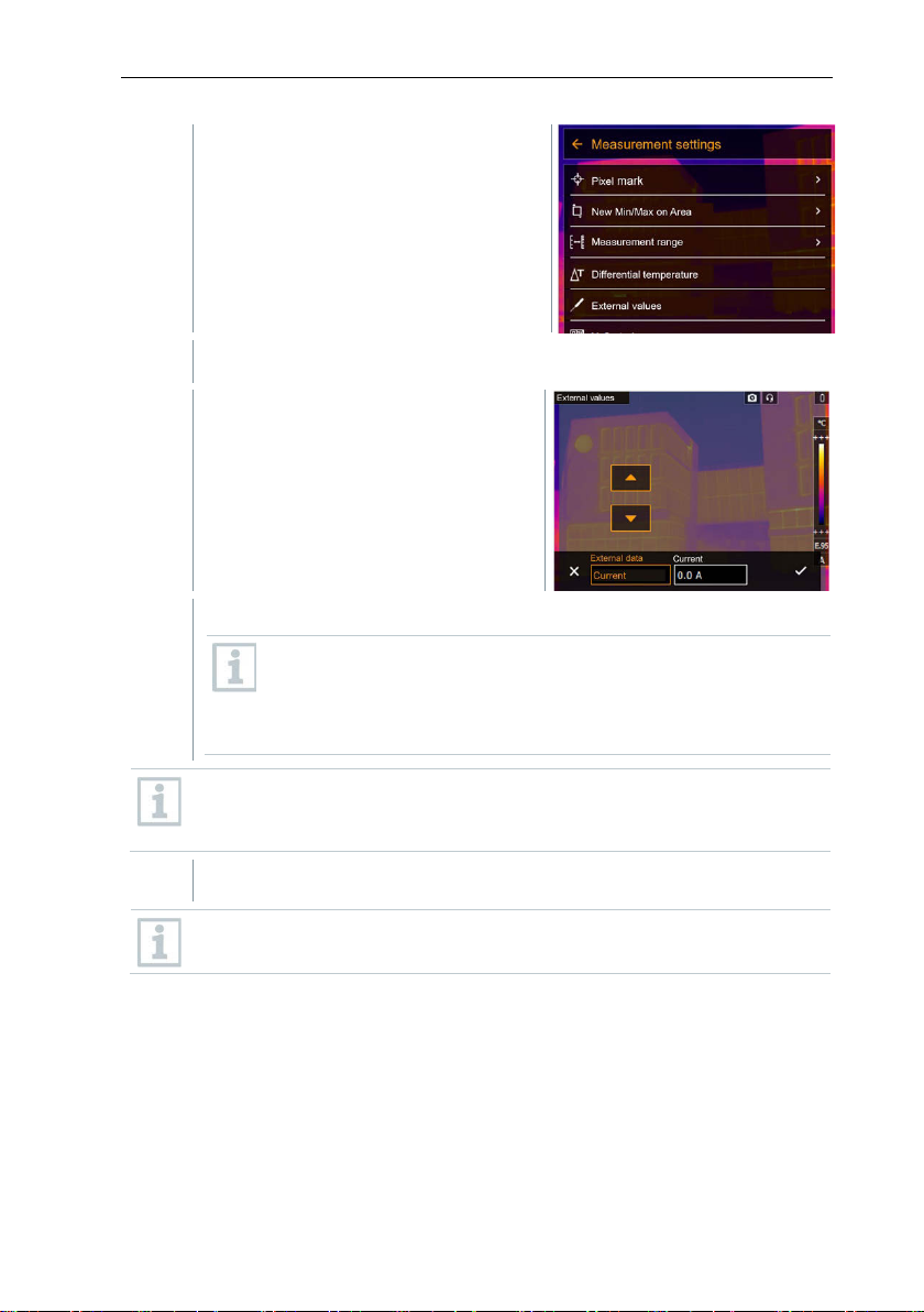
11 Performing the measurement
3
Select External values (joystick or touchscreen).
4
Activate humidity, current, voltage, solar or power.
5
Confirm with .
Measurement settings opens.
External values opens.
radio probe
If no
manually.
If a radio probe is connected, values are transferred
automatically.
is connected, values must be entered
The probe or the radio link to the probe must be activated in the
Configuration -> Connectivity menu. See Section 11.10.4
Connectivity.
Values for current, voltage and power can be transferred from the
testo 770-3 clamp meter.
11.2.5 SiteRecognition
With the PC software testo IRSoft QR Codes, markers can be set to clearly
identify a measuring location. By setting a marker with the built-in digital imager,
the images, which are then saved, are automatically allocated to the relevant
site (allocation is saved with this image). For the creation of markers,
transferring of measuring site data to the imager and copying of images to the
PC software, see instruction manual for the PC software.
36
Page 37
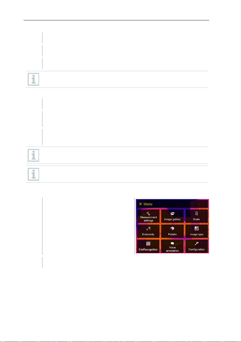
1
Open the Menu.
2
Select SiteRecognition function (joystick or touchscreen).
The real image is displayed and a position frame is shown.
1
Position the imager so that the marker is inside the position frame.
2
After recognition of the marker ID: confirm transfer of measuring site
data.
1
Open the Menu.
2
Select Measurement settings (joystick or touchscreen).
To quickly change the measuring locations, SiteRecognition can be
assigned to the quick select button.
Enter measuring site marker
The thermographic image that is taken next is assigned to the
measuring location.
Several images can be saved for the same measuring location.
To exit the measuring location, press Esc or touch the bottom left
corner. Run SiteRecognition again.
11.2.6 IFOV
11 Performing the measurement
37
Page 38
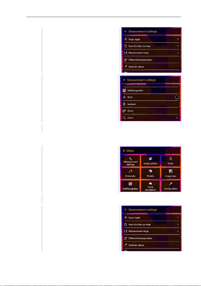
11 Performing the measurement
3
Select IFOV (joystick or touchscreen).
1
Open the Menu.
2
Select Measurement settings (joystick or touchscreen).
Measurement settings opens.
IFOV is enabled or disabled.
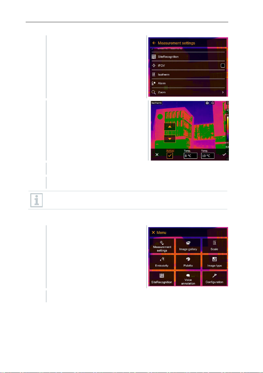
11.2.7 Isotherm
Measurement settings opens.
38
Page 39
3
Select Isotherm (joystick or
touchscreen).
4
limit values can be set.
5
Confirm with .
1
Open the Menu.
2
Select Measurement settings (joystick or touchscreen).
Isotherm opens.
The colours for the markings can be specified in the Configuration ->
Color selection menu.
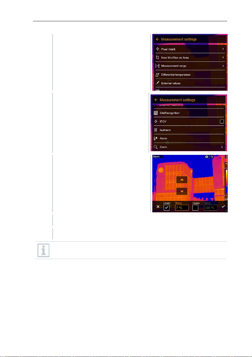
11.2.8 Alarm
11 Performing the measurement
39
Page 40
11 Performing the measurement
3
Select Alarm (joystick or
4
Upper and lower alarm limits can be set and activated individually.
5
Confirm with .
Measurement settings opens.
touchscreen).
Alarm opens.
The colours for the markings can be specified in the Configuration ->
Color selection menu.
40
Page 41
1
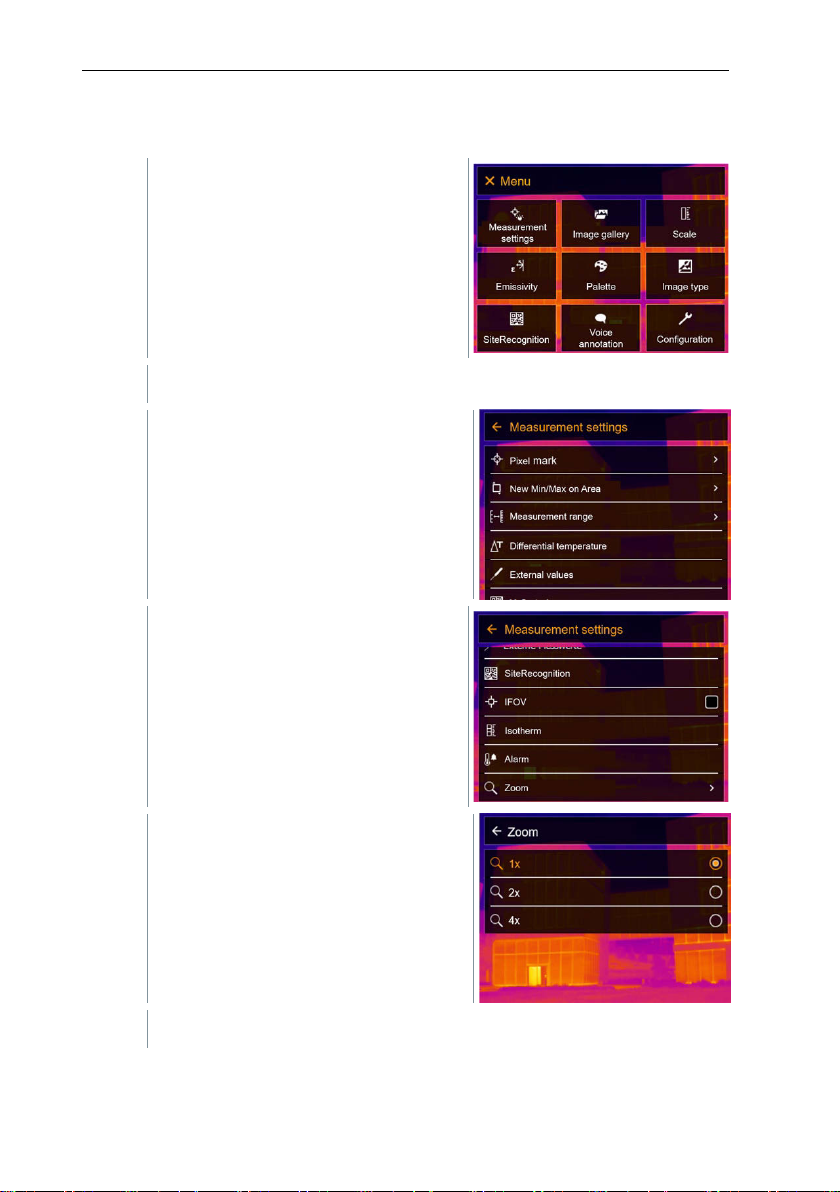
Open the Menu.
2
Select Measurement settings (joystick or touchscreen).
3
Select Zoom (joystick or
4
Select the required zoom factor (joystick or touchscreen).
11.2.9 Zoom
Measurement settings opens.
11 Performing the measurement
touchscreen).
Zoom opens.
41
Page 42
11 Performing the measurement
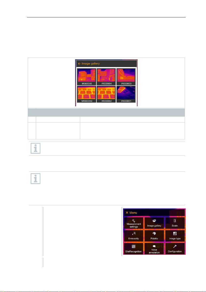
1 - Infrared image preview
2
IR
SR
Infrared image with attached real image
Images captured with SuperResolution
1
Open the Menu.
2
Select Image gallery (joystick or touchscreen).
11.3 Image gallery
Saved images can be displayed, analyzed or deleted. You can listen to and also
record a voice annotation subsequently or do it again.
File name
Element Function
Displaying a saved image
Saved images can be viewed and analyzed in the image gallery.
000000
Consecutive number
File names can be changed via the PC (not in the imager), e.g. in
Windows Explorer.
When SuperResolution is enabled, 2 images are saved in the image
gallery (an IR image, and an SR image). The high-resolution
SuperResolution image is saved in the background. In the status bar,
the number of SuperResolution images to be saved is displayed (for
example: SR(1) ). A maximum 5 SuperResolution images can be
processed simultaneously.
42
Page 43
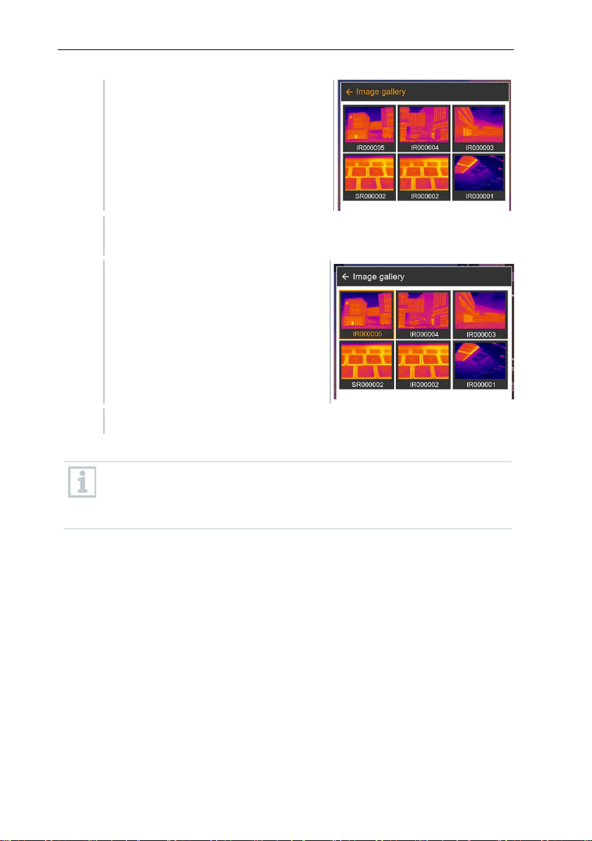
Image gallery opens.
3
Select image (joystick or
All saved images are displayed in the form of an infrared image
preview.
touchscreen).
The image is displayed.
Analyzing an image
11 Performing the measurement
If an image is saved with SuperResolution, the image gallery contains
an (IR) image and a high-resolution image (SR). The images show the
same image section. They can be displayed and analyzed in the image
gallery.
Analyze stored images using the measurement functions Single point
measurement, Hotspot, Coldspot, Additional measurement points,
Differential temperature, Isotherm and Alarm.
For a description of the individual functions, please read the information in the
relevant sections.
43
Page 44
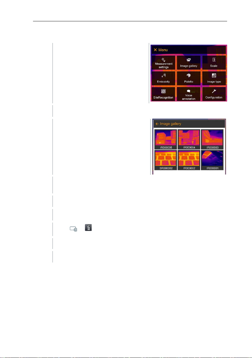
11 Performing the measurement
1
Open the Menu.
2
Select Image gallery (joystick or touchscreen).
3
Move joystick to select an image.
4
Press Ok to open an image.
5
6
Confirm selection with or exit the menu with X.
Delete image
Image gallery opens.
All saved images are displayed in the form of an infrared image
preview.
Press or at bottom right.
Delete image? is displayed.
11.4 Scale
Manual scaling can be activated instead of automatic scaling (continuous
automatic adjustment to the current min./max. values). The scale limits can be
set within the measurement range.
The activated mode is displayed bottom right: A automatic scaling, M manual
scaling and S ScaleAssist.
44
Page 45
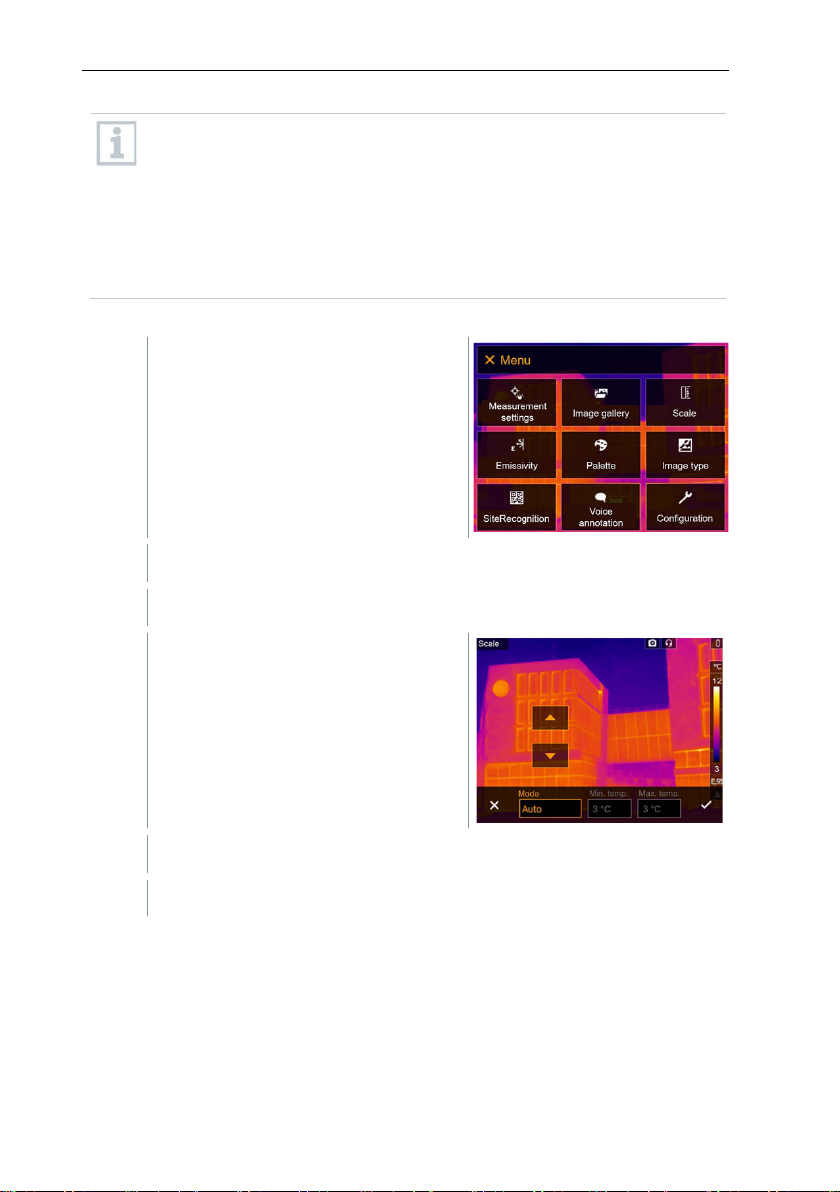
Auto
1
Open the Menu.
2
Select Scale (joystick or touchscreen).
3
Select Auto.
4
Confirm selection with or exit the menu with X.
-scaling continuously adjusts the scale to the readings presented,
and the colour assigned to a temperature value changes. In manual
scaling fixed limit values are defined, and the colour assigned to a
temperature value is fixed (important for visual image comparisons).
Scaling influences the way the infrared image is shown on the display
but does not affect the recorded measuring values.
With ScaleAssist, a standardized scale is set depending on the inside
and outside temperature.
Setting automatic scaling
Scale opens.
11 Performing the measurement
Setting manual scaling
The lower limit value, the temperature range (upper and lower limit value
simultaneously) and the upper limit value can be set.
Automatic scaling is activated. A is displayed bottom right.
45
Page 46
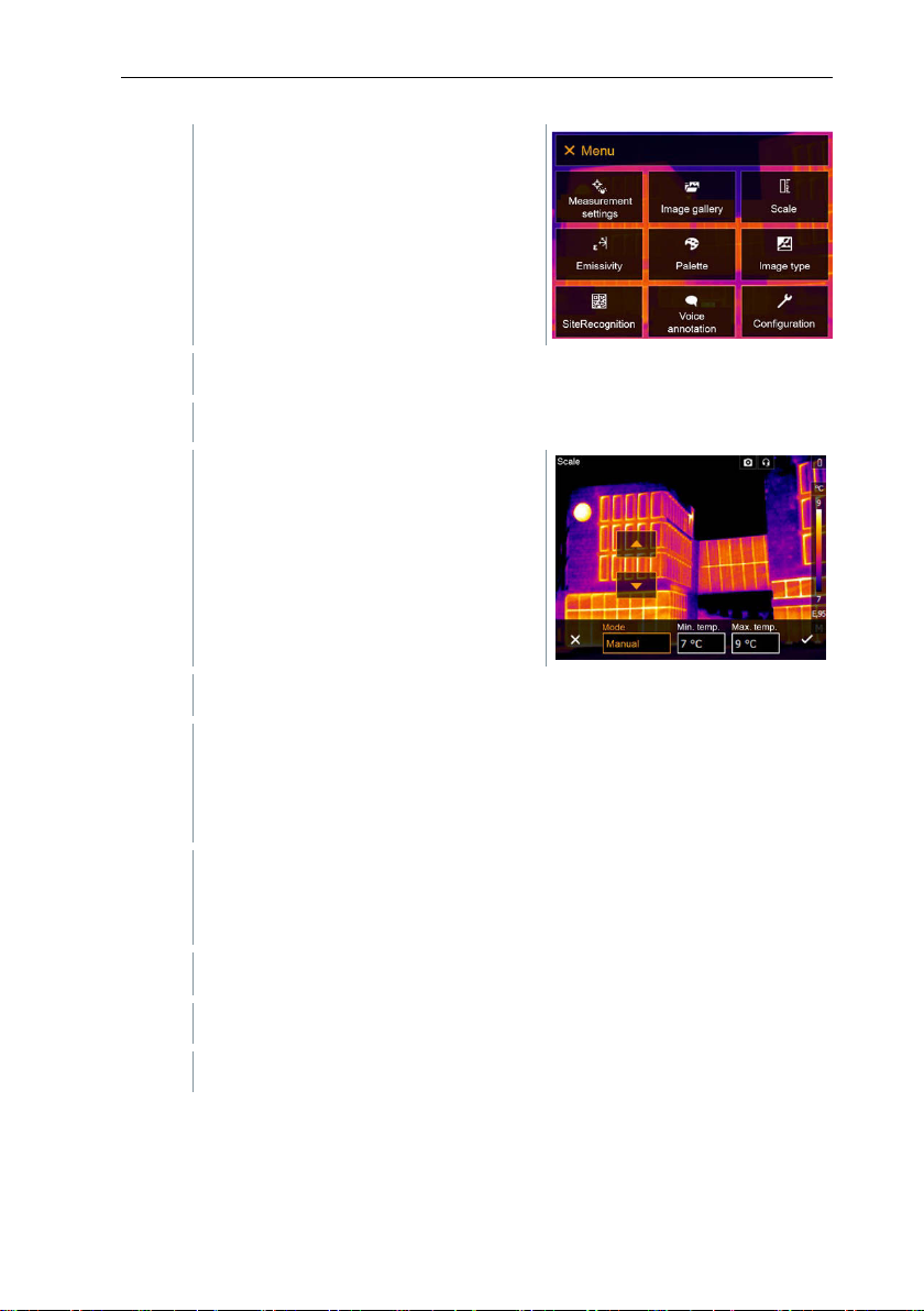
11 Performing the measurement
1
Open the Menu.
2
Select Scale (joystick or touchscreen).
3
Select Manual.
4
Move the joystick to the right, select Min.Temp. (lower limit value).
4.1
Move the joystick to the right, select Min.Temp. (lower limit value) and
4.2
Move the joystick to the right, select Max.Temp. (upper limit value).
4.3
If necessary, move the joystick to the left, back to the mode menu.
5
Confirm selection with or exit the menu with X.
Scale opens.
Max.Temp. (upper limit value).
Move the joystick up/down to set the values.
Move the joystick up/down to set the value.
Setting up ScaleAssist
The ScaleAssist function calculates a display-neutral scale depending on the
inside and outside temperature. This scale graduation can be used to detect
structural defects in buildings.
46
Manual scaling is activated. M is displayed bottom right.
Page 47
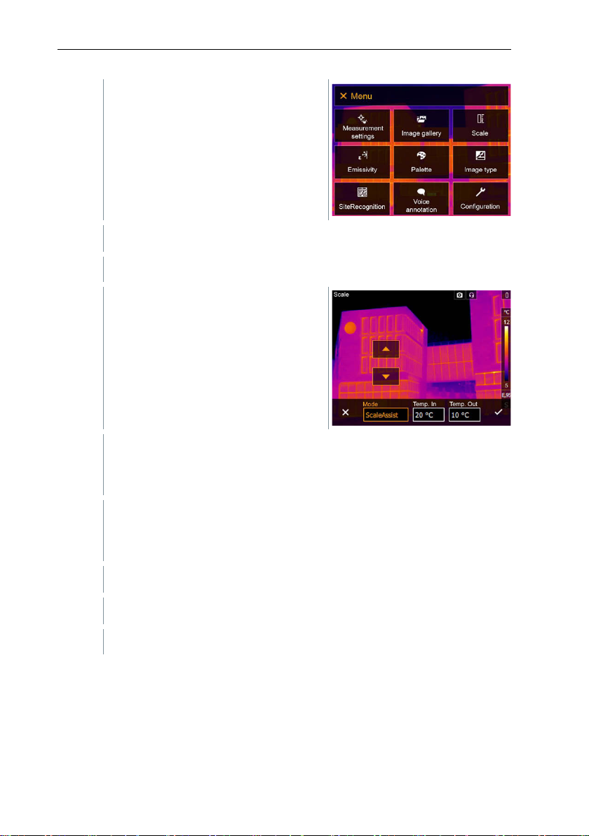
11 Performing the measurement
1
Open the Menu.
2
Select Scale (joystick or touchscreen).
3
Select ScaleAssist.
4
Move the joystick to the right, select Temp. In (indoor temperature).
5
Move the joystick to the right, select Temp. Out (outdoor temperature).
6
If necessary, move the joystick to the left, back to the mode menu.
7
Confirm selection with or exit the menu with X.
Scale opens.
Move the joystick up/down to set the value.
Move the joystick up/down to set the value.
Manual scaling is activated. S is displayed at bottom right.
11.5 Emissivity
You can choose between user-defined emissivity and 8 materials with
permanently set emissivity. The reflected temperature (RTC) can be set
individually.
47
Page 48
11 Performing the measurement
materials can be imported into the instrument from an existing list
Aluminium, bright rolled (170 °C)
0.04
Cotton (20 °C)
0.77
Concrete (25 °C)
0.93
Ice, smooth (0 °C)
0.97
Iron, emery-ground (20 °C)
0.24
Iron with casting skin (100 °C)
0.80
Iron with rolling skin (20 °C)
0.77
Gypsum (20 °C)
0.90
Glass (90 °C)
0.94
Rubber, hard (23 °C)
0.94
Rubber, soft grey (23 °C)
0.89
Wood (70 °C)
0.94
Cork (20 °C)
0.70
Radiator, black anodised (50 °C)
0.98
Copper, slightly tarnished (20 °C)
0.04
Copper, oxidised (130 °C)
0.76
Plastics: PE, PP, PVC (20 °C)
0.94
Brass, oxidised (200 °C)
0.61
Paper (20 °C)
0.97
Porcelain (20 °C)
0.92
Black paint, matt (80 °C)
0.97
Steel, heat-treated surface (200 °C)
0.52
Other
using the PC software.
Emissivity information:
The emissivity describes the capability of a body to emit electromagnetic
radiation. This is material-specific and must be adapted for correct
measurement results.
Non-metals (paper, ceramic, gypsum, wood, paints and coatings), plastics and
food have high emissivity, which means that the surface temperature can be
easily measured using infrared.
Because of their low or non-uniform emissivity, bright metals and metal oxides
only have limited suitability for infrared measurement. Highly inaccurate
measurements should be expected. A remedy for this is coatings that increase
emissivity, e.g. paint or emission adhesive (accessory: 0554 0051), which must
be applied to the object to be measured.
The following table gives typical emissivities of important materials. These
values can be used as a guide for user-defined settings.
Material (material temperature) Emissivity
48
Page 49
11 Performing the measurement
Steel, oxidised (200 °C)
0.79
Clay, burnt (70 °C)
0.91
Transformer paint (70 °C)
0.94
Brick, mortar, plaster (20 °C)
0.93
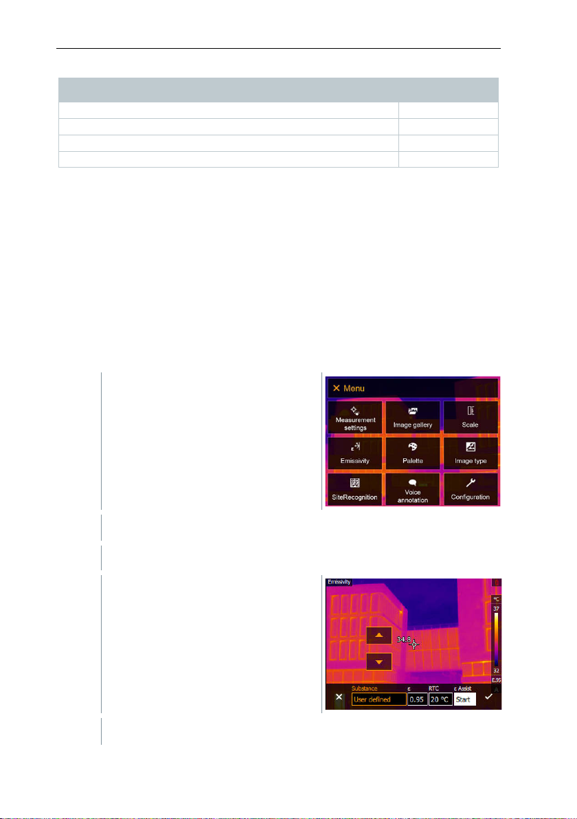
1
Open the Menu.
2
Select Emissivity (joystick or touchscreen).
3
Select Substance.
4
Confirm selection with or exit the menu with X.
Material (material temperature) Emissivity
Reflected temperature information:
Using this offset factor, the reflection is calculated out based on the low
emissivity, and the accuracy of the temperature measurement with infrared
measuring instruments is improved. In most cases, the reflected temperature is
identical to the ambient air temperature. Only when objects with strong
emissions at much lower temperatures (such as cloudless skies during outdoor
readings) or much higher temperatures (such as ovens or machines) are in
proximity to the object being measured should the radiation temperature of
these sources be determined and used. The reflected temperature has little
effect on objects with high emissivity.
@ Further information can be found in the Pocket Guide.
11.5.1 Selecting the emissivity
Emissivity opens.
49
Page 50
11 Performing the measurement
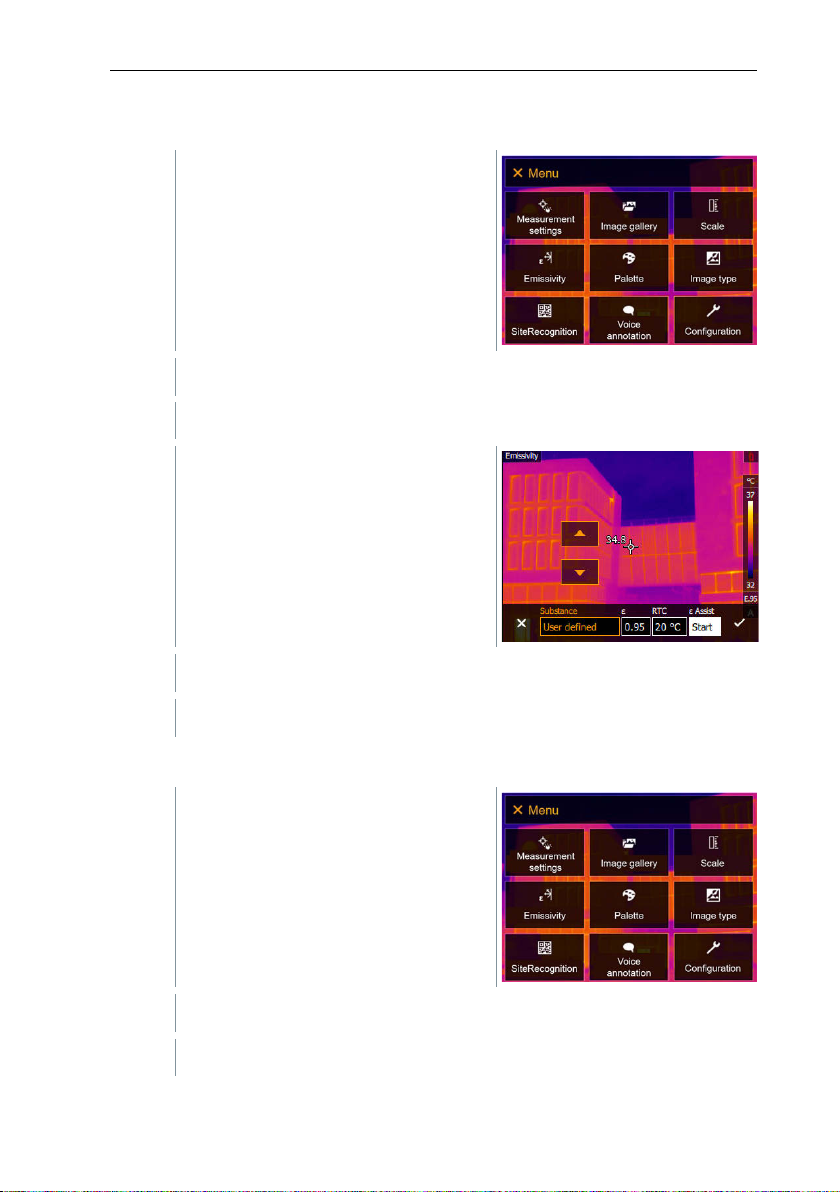
1
Open the Menu.
2
Select Emissivity (joystick or touchscreen).
3
Under Substance, select User
4
Select E and set the value.
5
Confirm selection with or exit the menu with X.
1
Open the Menu.
2
Select Emissivity (joystick or touchscreen).
11.5.2 Customizing the emissivity
Emissivity opens.
defined.
11.5.3 Setting RTC
50
Emissivity opens.
Page 51
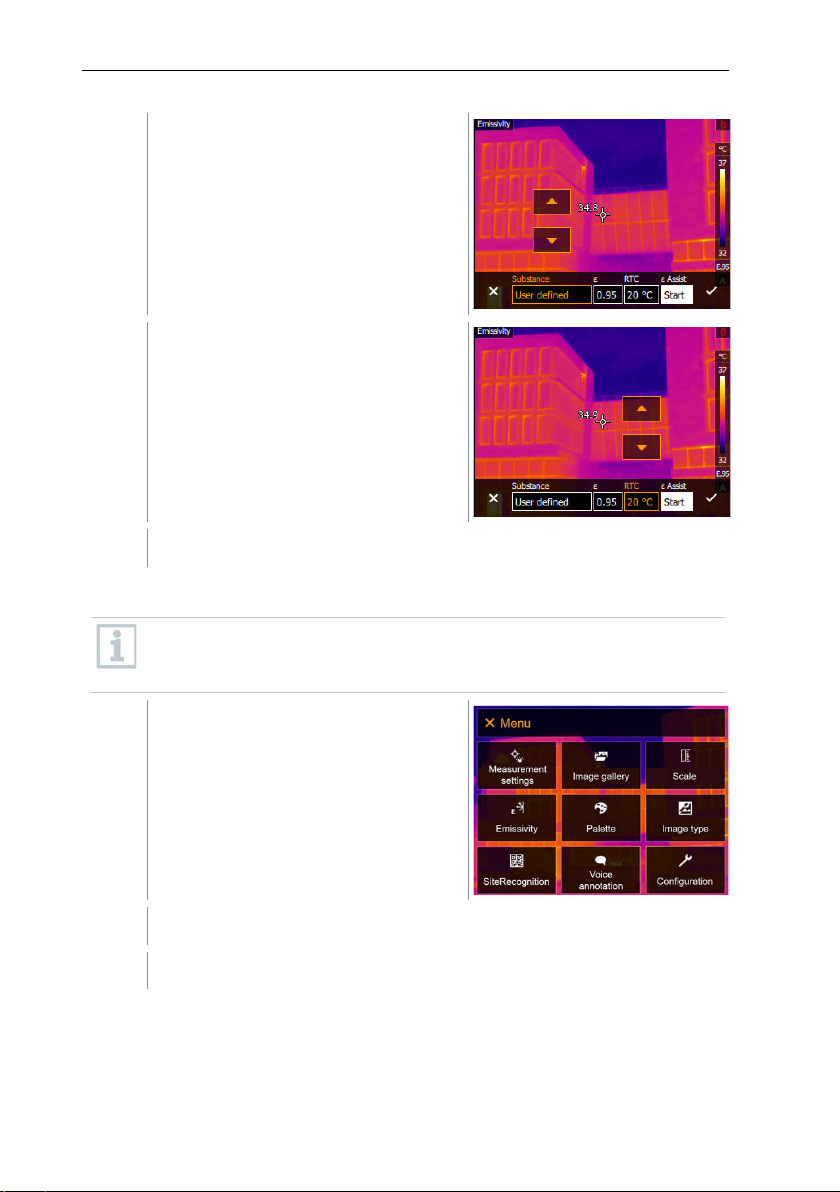
3
Select Substance.
4
Select RTC and set the value.
5
Confirm selection with or exit the menu with X.
1
Open the Menu.
2
Select Emissivity (joystick or touchscreen).
11.5.4 Setting ε-Assist
An additional marker for the ε-assist function is required for this
function. Additional markers for the ε-assist function are available as
accessories.
11 Performing the measurement
Emissivity opens.
51
Page 52
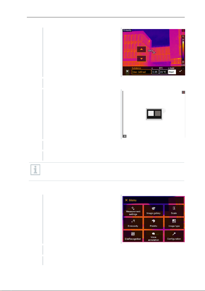
11 Performing the measurement
3
Select Substance.
4
Select ε-Assist.
5
Attach the ε-marker to the object.
6
Confirm selection with or exit the menu with X.
1
Open the Menu.
2
Select Palette (joystick or touchscreen).
RTC and emissivity are automatically adjusted.
If it is not physically possible to determine the emissivity due to the
same object temperature and reflected temperature, the input field
opens again. The emission value must be input manually.
11.6 Palette
52
Palette opens.
Page 53
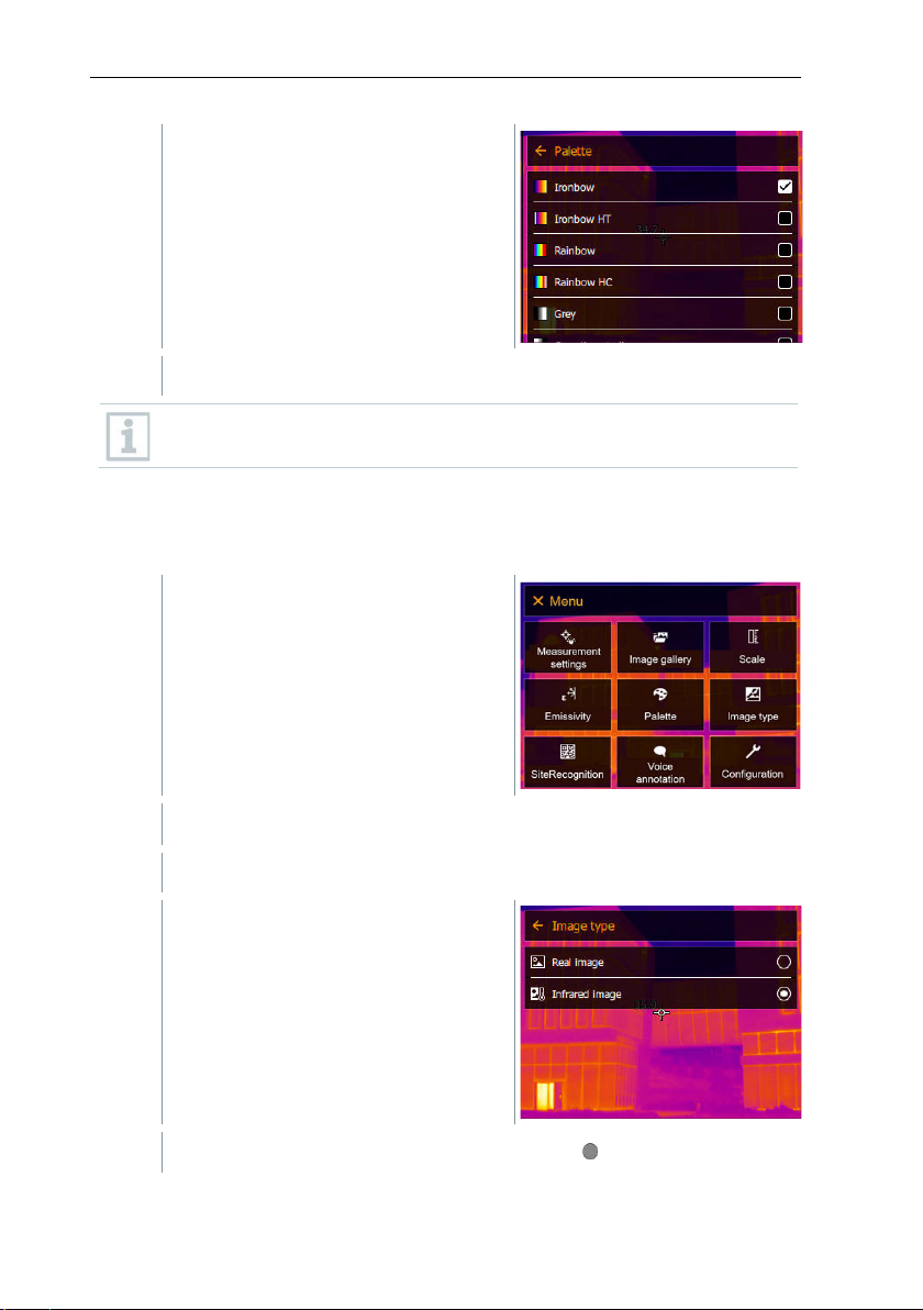
11 Performing the measurement
3
Select the required colour palette
1
Open the Menu.
2
Select Image type (joystick or touchscreen).
3
Select the required image type
(joystick or touchscreen).
The colour palette is marked .
In the live image, the palette can be changed by moving the joystick up
or down.
11.7 Image type
The display can be switched between infrared image and real image (digital
camera).
Image type opens.
(joystick or touchscreen).
The activated image type is marked with a dot ( ).
53
Page 54
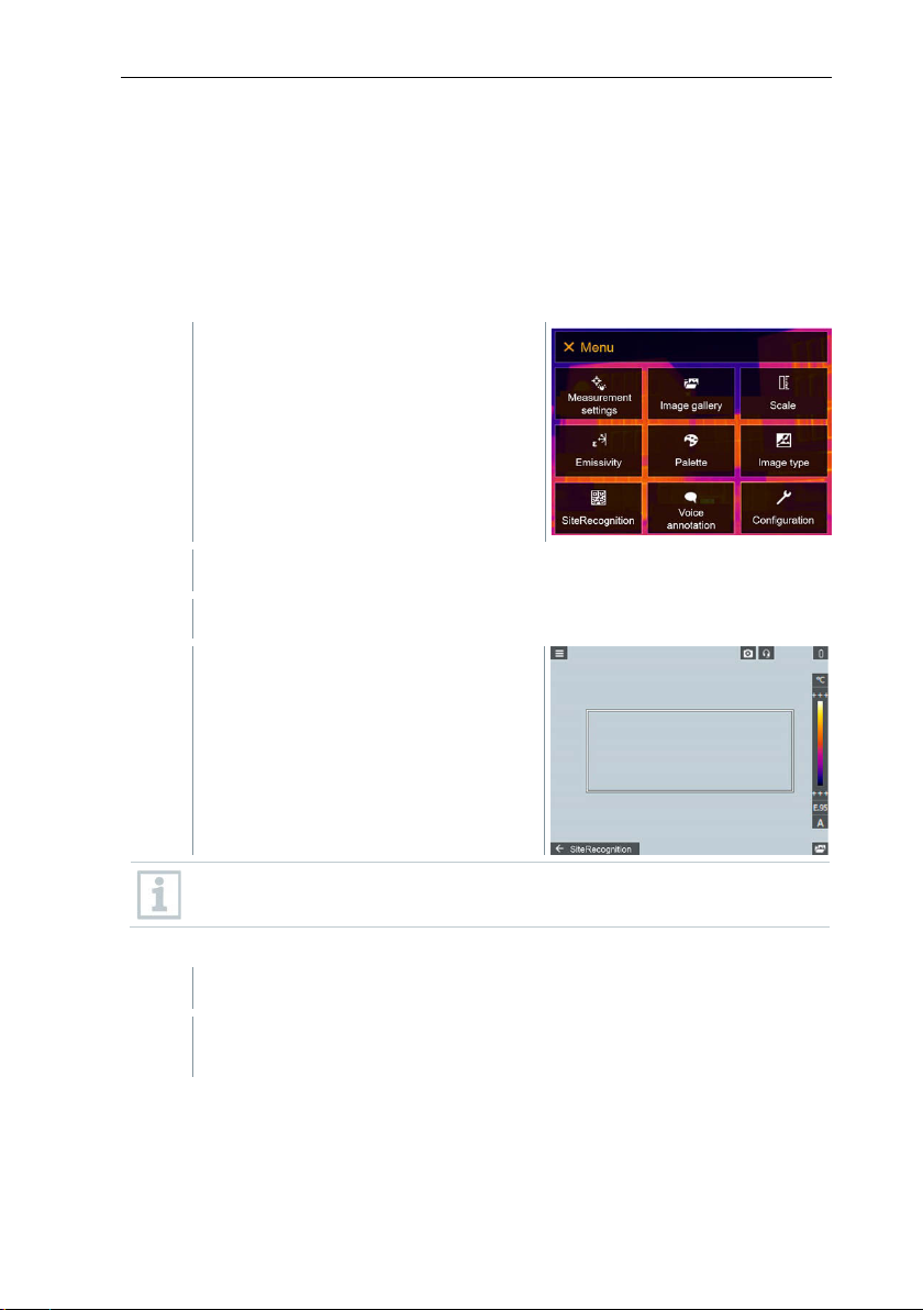
11 Performing the measurement
1
Open the Menu.
2
Select SiteRecognition (joystick or touchscreen).
1
Position the imager so that the marker is inside the position frame.
2
After recognition of the marker ID: confirm transfer of measuring site
data.
11.8 SiteRecognition
With the PC software testo IRSoft QR Codes, markers can be set to clearly
identify a measuring location. By setting a marker with the built-in digital imager,
the images, which are then saved, are automatically allocated to the relevant
site (allocation is saved with this image). For the creation of markers,
transferring of measuring site data to the imager and copying of images to the
PC software, see instruction manual for the PC software.
SiteRecognition opens.
The real image is displayed and a
position frame is shown.
To quickly change the measuring locations, SiteRecognition can be
assigned to the quick select button.
Enter measuring site marker
54
Page 55
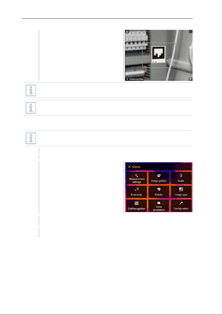
The thermographic image that is
An image has just been created or selected from the image gallery.
1
Open the Menu.
2
Select Voice annotation (joystick or touchscreen).
taken next is assigned to the
measuring location.
Several images can be saved for the same measuring location.
To exit the measuring location, press Esc or touch the bottom left
corner. Run SiteRecognition again.
11.9 Voice annotation
Voice annotation can only be used when an image is active on the
display.
11 Performing the measurement
Voice annotation opens.
55
Page 56
11 Performing the measurement
3
4
5
6
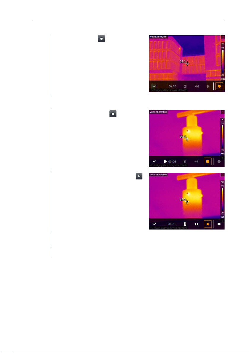
Press to confirm the recording.
Click on recording .
Recording timer starts running.
Click on stop recording .
The recording can be played back ,
rewound or deleted.
The voice annotation is stored in the image.
11.10 Configuration
11.10.1 Settings
Country settings
The user interface language can be set.
56
Page 57
11 Performing the measurement
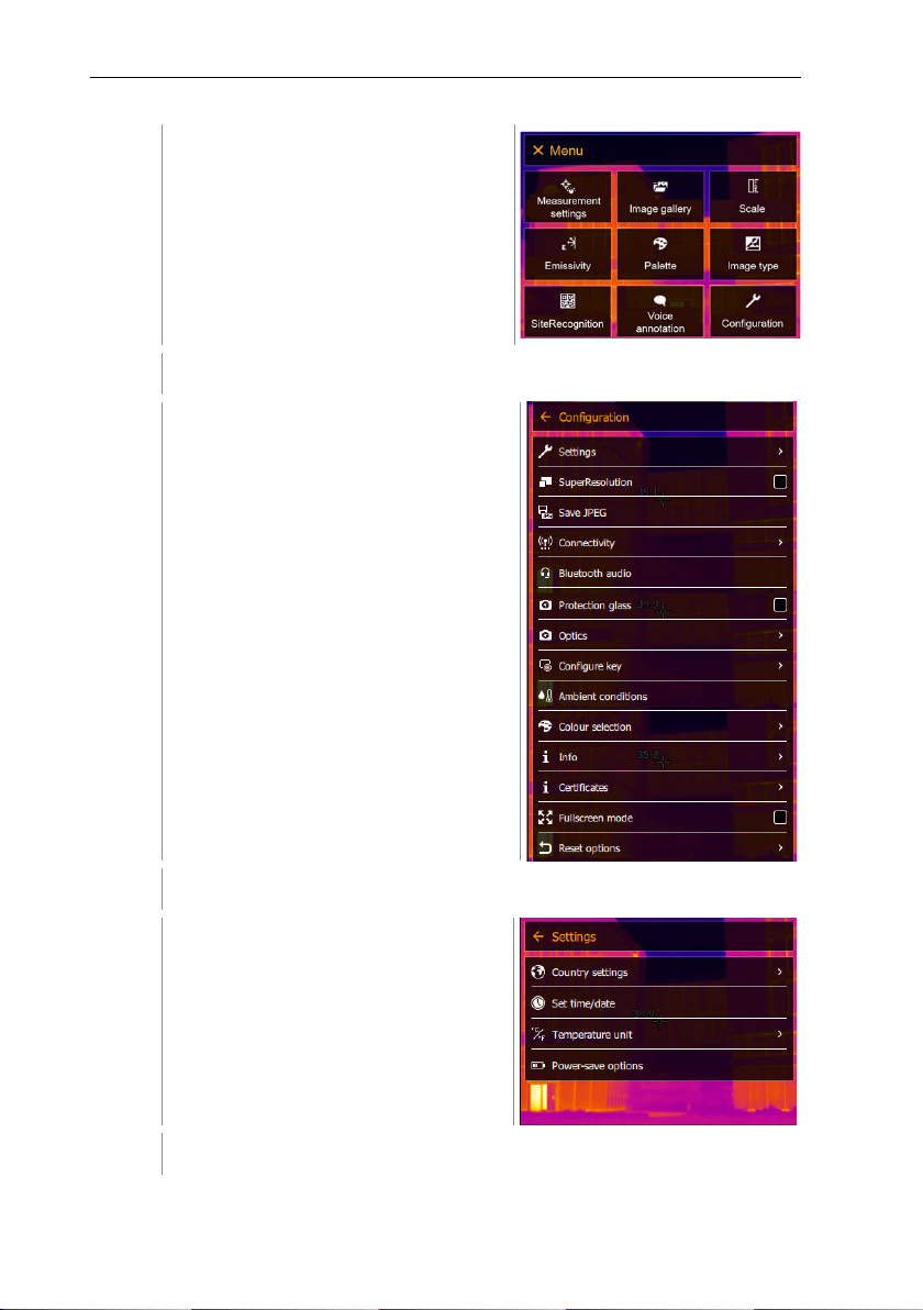
1
Open the Menu.
2
Select Configuration (joystick or touchscreen).
3
Select Settings (joystick or touchscreen).
4
Select Country settings.
Configuration opens.
Settings opens.
57
Page 58
11 Performing the measurement
5
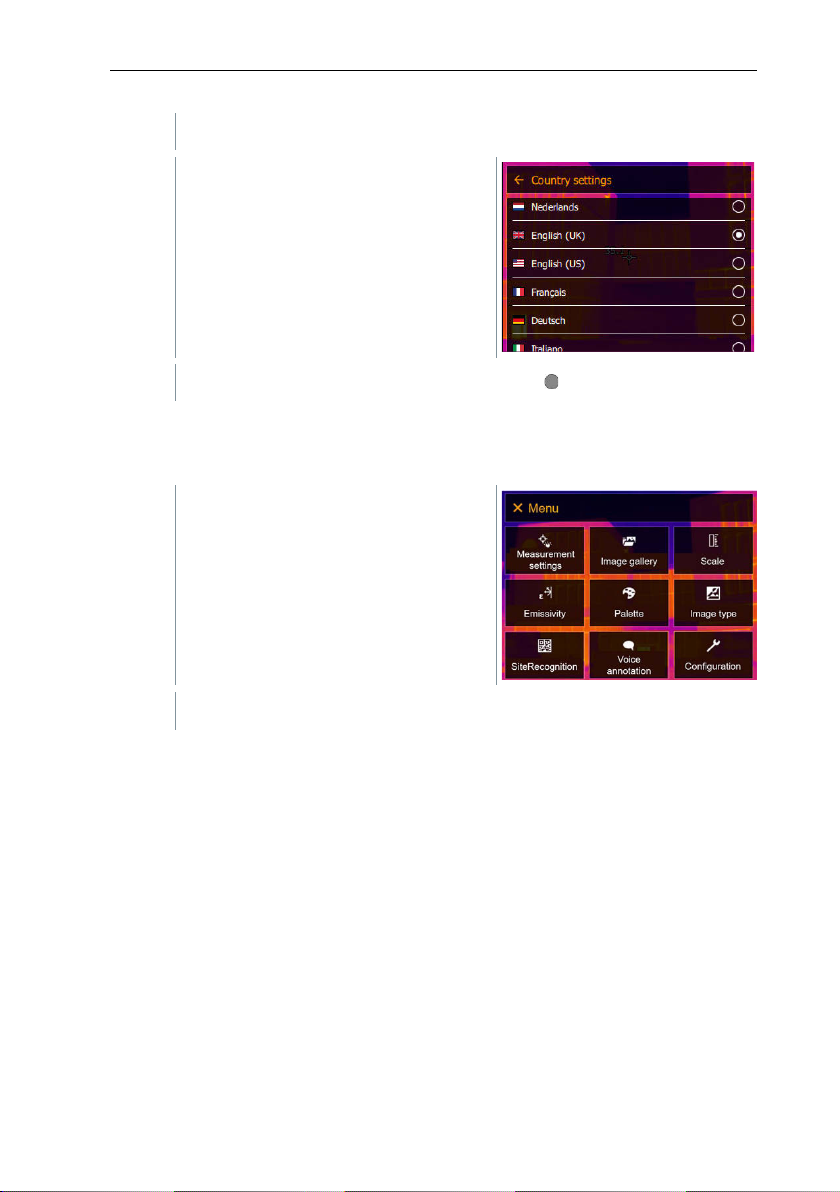
Select the required language (joystick
1
Open the Menu.
2
Select Configuration (joystick or touchscreen).
or touchscreen).
[Country settings] opens.
The activated language is marked with a dot ( ).
Set time/date
Time and date can be set. The time and date format are set automatically based
on the selected user interface language.
58
Page 59
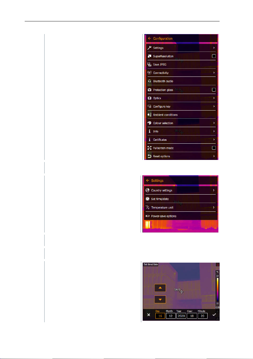
11 Performing the measurement
3
Select Settings (joystick or touchscreen).
4
Select [Set time/date] (joystick or touchscreen).
5
Set the time and date (joystick or
Configuration opens.
Settings opens.
[Set time/date] opens.
touchscreen).
59
Page 60
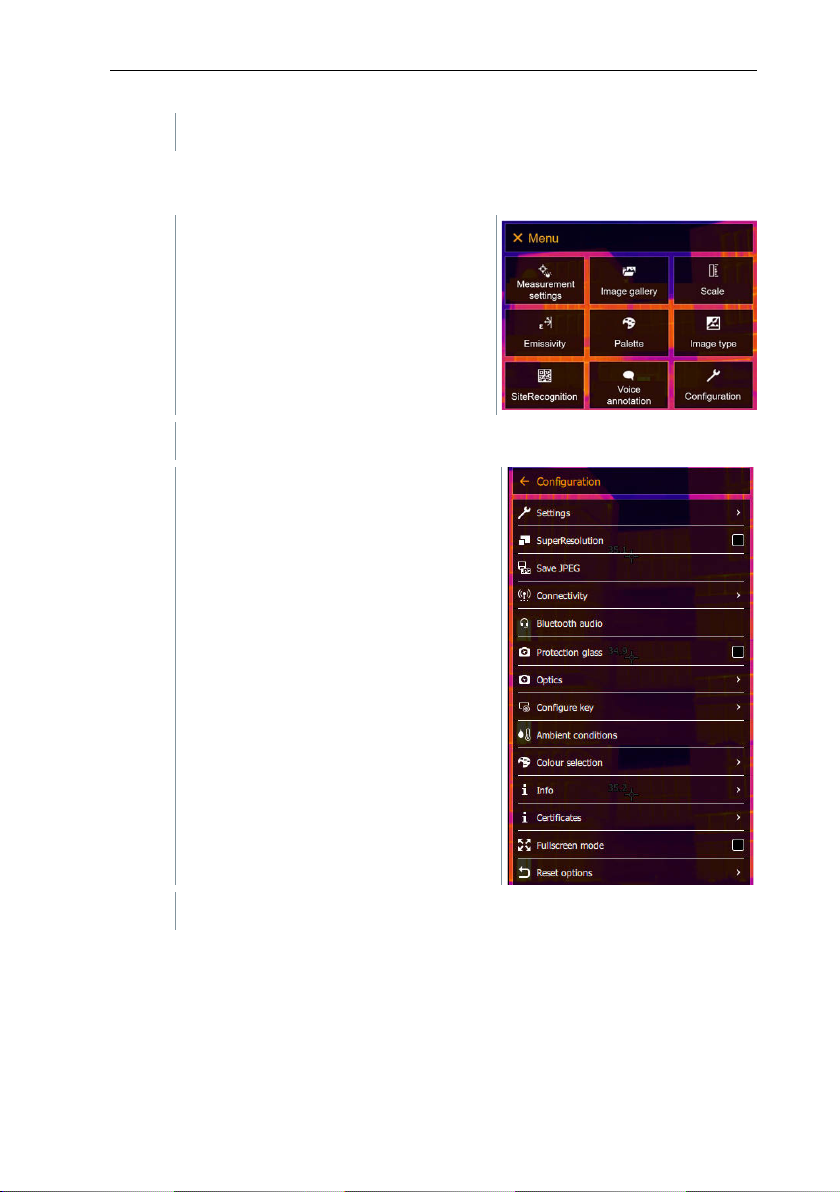
11 Performing the measurement
6
Confirm selection with or exit the menu with X.
1
Open the Menu.
2
Select Configuration (joystick or touchscreen).
3
Select Settings (joystick or touchscreen).
Temperature unit
The temperature unit can be set.
Configuration opens.
60
Page 61
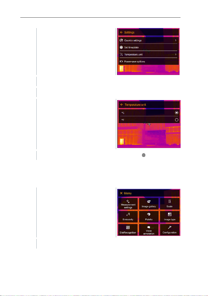
11 Performing the measurement
4
Select [Temperature unit] (joystick or touchscreen).
5
Set the temperature unit (joystick or
1
Open the Menu.
2
Select Configuration (joystick or touchscreen).
Settings opens.
Power-save options
The illumination intensity of the display can be set. A lower intensity increases
the battery life.
The time until automatic switch-off can be set between 5 min and 300 min.
[Temperature unit] opens.
touchscreen).
The activated temperature unit is marked with a dot ( ).
61
Page 62
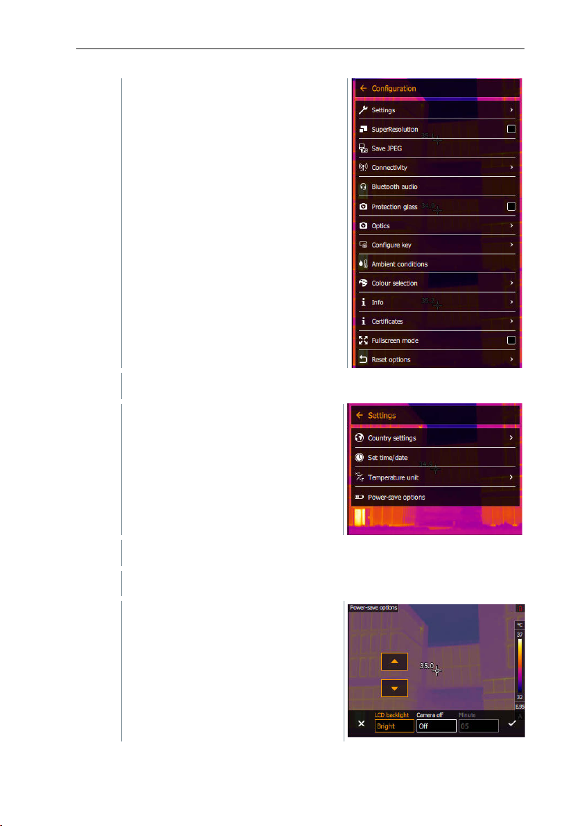
11 Performing the measurement
3
Select Settings (joystick or touchscreen).
4
Select [Power-save options] (joystick or touchscreen).
5
Set the power-save options (joystick
Configuration opens.
Settings opens.
62
[Power-save options] opens.
or touchscreen).
Page 63
11 Performing the measurement
6
Confirm selection with or exit the menu with X.
1
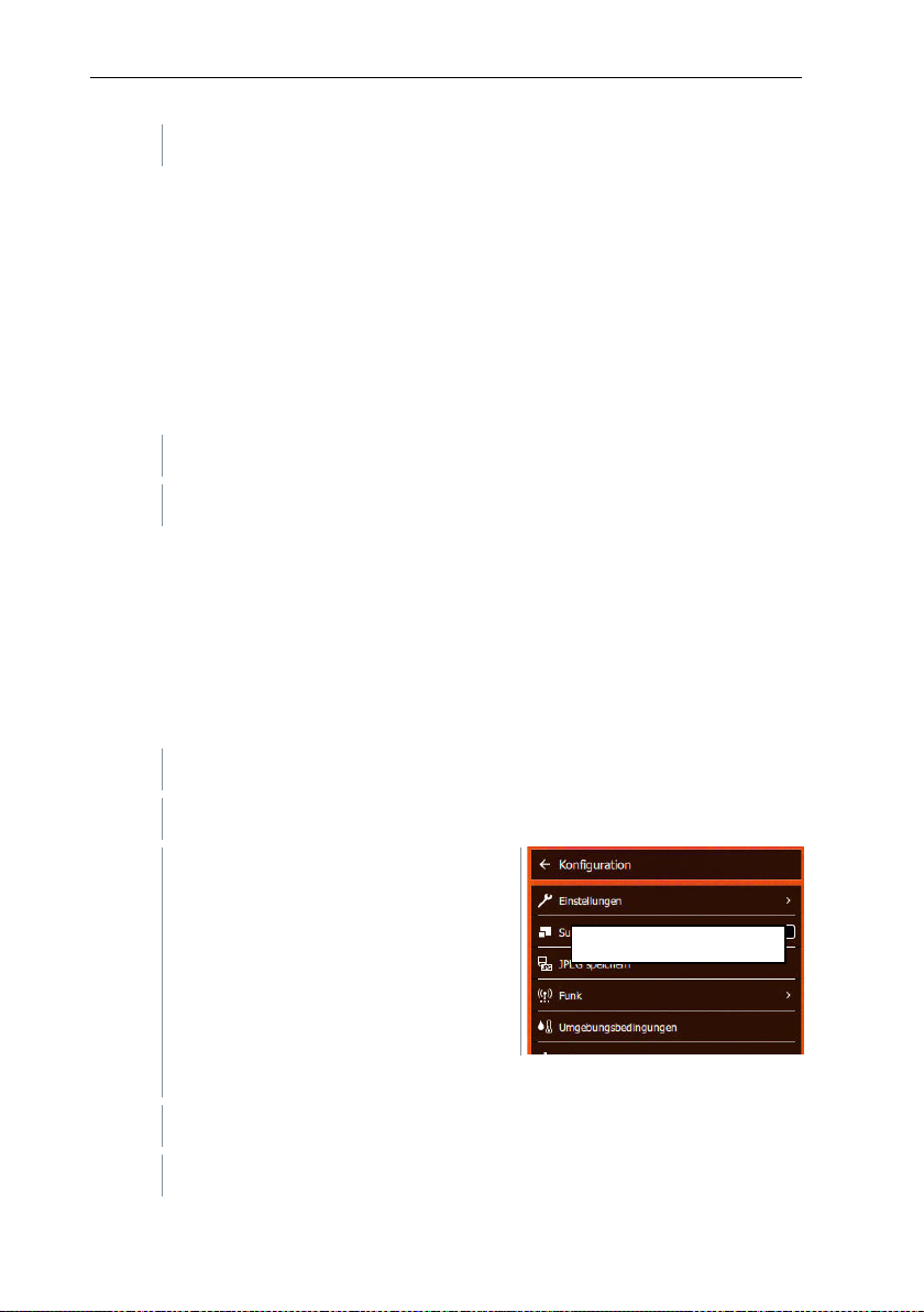
Open the SuperResolution function.
2
Press OK to enable or disable the function.
1
Open the Menu.
2
Select Configuration (joystick or touchscreen).
3
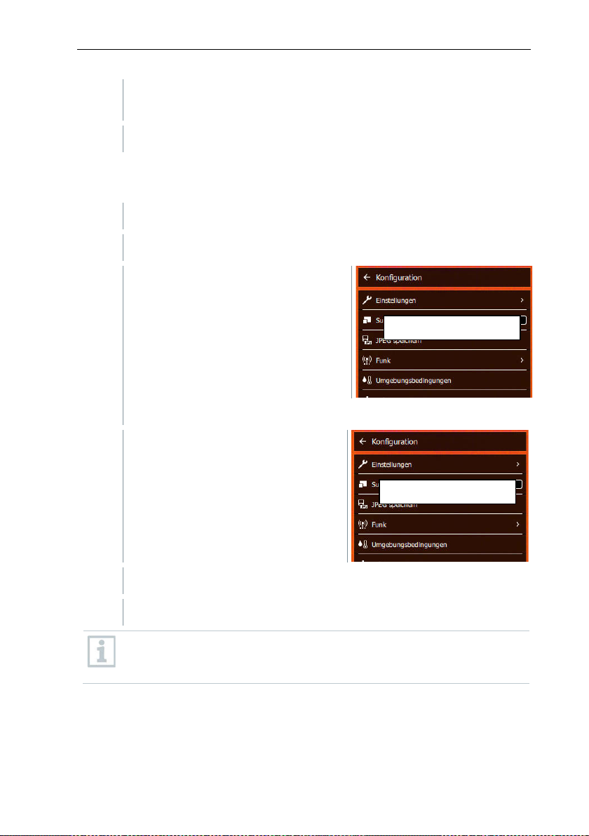
Select Save JPEG (joystick or touchscreen).
3
Move the joystick up/down until On/Off is selected.
4
Press OK.
Replace screen EN
11.10.2 SuperResolution
SuperResolution is a technology to improve image quality. For each shot a
sequence of images is saved in the thermal imager. Using the camera, App, or
PC software, an image is recorded with four times more measurement values
(no interpolation). The geometric resolution (IFOV) is improved by a factor of
1.6.
To use the function, the following conditions must be fulfilled:
• The camera is hand-held.
• The objects to be imaged do not move.
11.10.3 Save JPEG
Infrared images are saved in BMT (image with all temperature data) format. The
image can also be saved in JPEG format (without temperature data) at the
same time. The image content corresponds to the infrared image shown on the
display, including scale display and image marks for the selected measuring
functions. The JPEG file is saved under the same file name as the associated
BMT file and can be opened on the PC, even without using the IRSoft PC
software.
Configuration opens.
63
Page 64
11 Performing the measurement
5
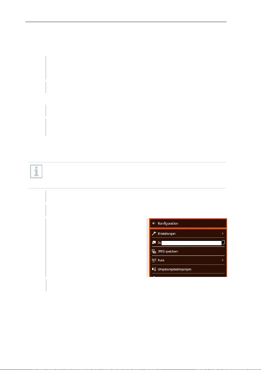
Add a date/time stamp to a JPEG file if required. Turn function on or off
6
Confirm with .
1
Open the Menu.
2
Select Configuration (joystick or touchscreen).
3
Select Connectivity (joystick or touchscreen).
4
Select WLAN or Bluetooth and press OK
5
Press Esc to cancel the process.
activated in addition, the Bluetooth data transfer is continued. However,
Replace screen EN
Replace screen EN
for this.
11.10.4 Connectivity
Enable/disable WLAN or Bluetooth®.
Configuration opens.
Connectivity opens.
If there is an active Bluetooth connection and a WLAN connection is
it is not possible to establish a new connection to a humidity probe.
64
Page 65
11 Performing the measurement
1
Place the protective glass (with black mount) attached to the red
it stops.
2
Remove the red mounting ring from the protection glass.
1
Attach the red mounting ring to the protection glass.
2
Turn the mounting ring anti-clockwise and remove the protective
glass.
Ensure the correct setting to prevent corruption of the measurement
guaranteed
1
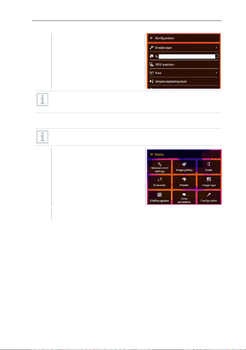
Open the Menu.
2
Select Configuration (joystick or touchscreen).
3
Select Protective glass (joystick or touchscreen).
11.10.5 Protective glass
Mounting the IR protective glass
mounting ring onto the lens and turn the mounting ring clockwise until
Removing the IR protective glass
Enable/disable protective glass option
Use the Protective glass option to select whether or not to use an IR protective
glass.
results.
If this option is set incorrectly, the specified measuring accuracy is not
Configuration opens.
65
Page 66
11 Performing the measurement
1
Open the Menu.
2
Select Configuration (joystick or touchscreen).
Protective glass is enabled (✔) or
disabled.
Using the protective glass protects the optics from environmental
influences such as dust, scratches, etc. When the protective glass is
used, there may be slight variations in the displayed temperature.
11.10.6 Lens
All lenses that can be used with the testo 883 are displayed with a
serial number for identification.
66
Page 67
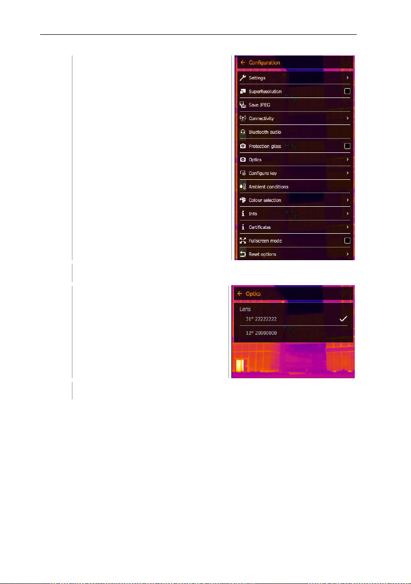
11 Performing the measurement
3
Select Optics (joystick or touchscreen).
Configuration opens.
Optics opens.
The lens used is marked .
67
Page 68
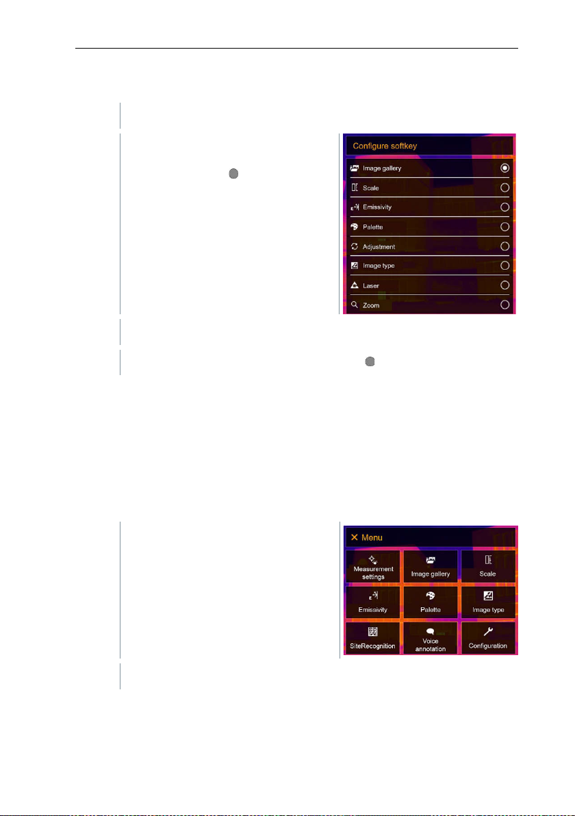
11 Performing the measurement
1
Move the joystick to the right.
2
Select the required menu item (joystick or touchscreen).
1
Open the Menu.
2
Select Configuration (joystick or touchscreen).
11.10.7 Quick select button
The Configure key selection menu
opens. The activated function is
marked with a dot ( ).
The activated function is marked with a dot ( ).
11.10.8 Ambient conditions
Measurement deviations arising due to high humidity or large distances to the
object to be measured can be corrected. Correction parameters must be
entered for this.
If the camera is connected to an optional humidity radio probe, the ambient
temperature and humidity are transferred automatically.
Values for ambient temperature (Temperature) and ambient humidity (Humidity)
can be set manually.
68
Page 69
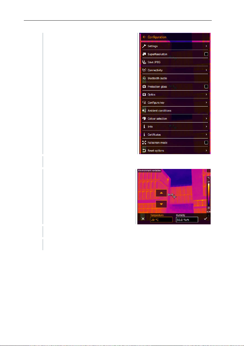
11 Performing the measurement
3
Select Ambient conditions (joystick or touchscreen).
4
Select the required setting (joystick or touchscreen).
5
Confirm selection with or exit the menu with X.
Configuration opens.
Ambient conditions opens.
69
Page 70
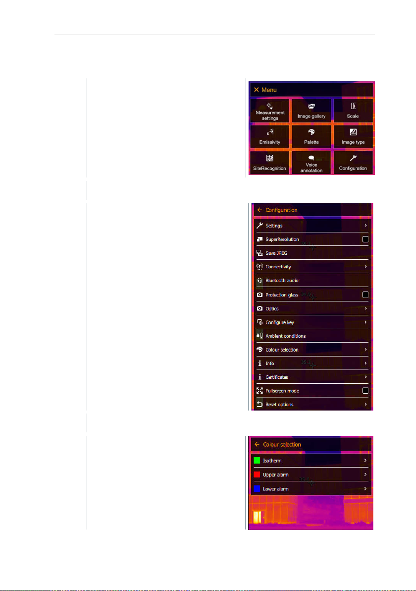
11 Performing the measurement
1
Open the Menu.
2
Select Configuration (joystick or touchscreen).
3
Select Color selection (joystick or touchscreen).
11.10.9 Color selection
Configuration opens.
Color selection opens.
70
Page 71
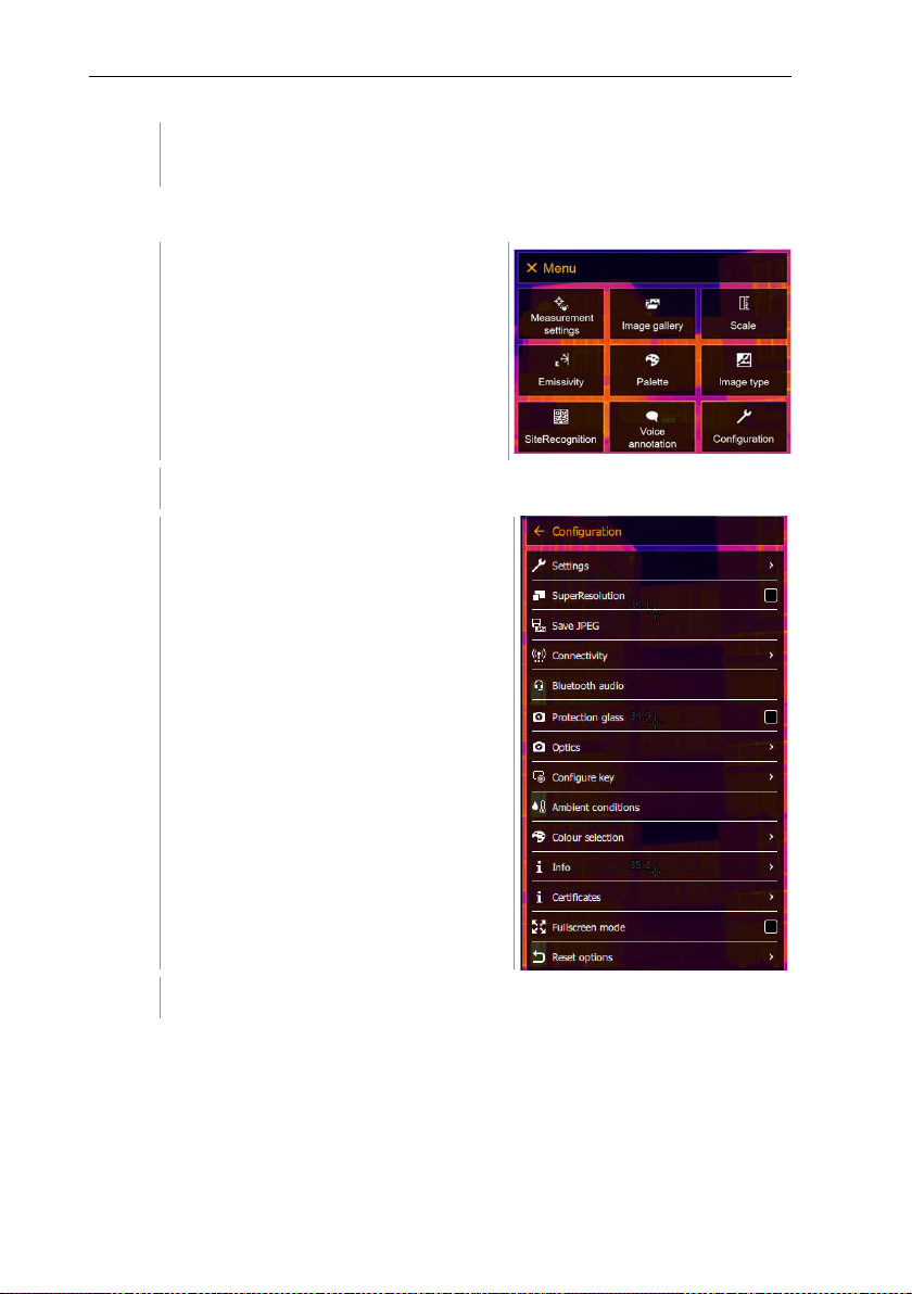
4
Select colour (red, green, blue, black, white, grey) for the Isotherm,
Upper Alarm and Lower Alarm markings (joystick or touchscreen).
1
Open the Menu.
2
Select Configuration (joystick or touchscreen).
3
Select Info (joystick or touchscreen).
11.10.10 Info
Configuration opens.
11 Performing the measurement
71
Page 72
11 Performing the measurement
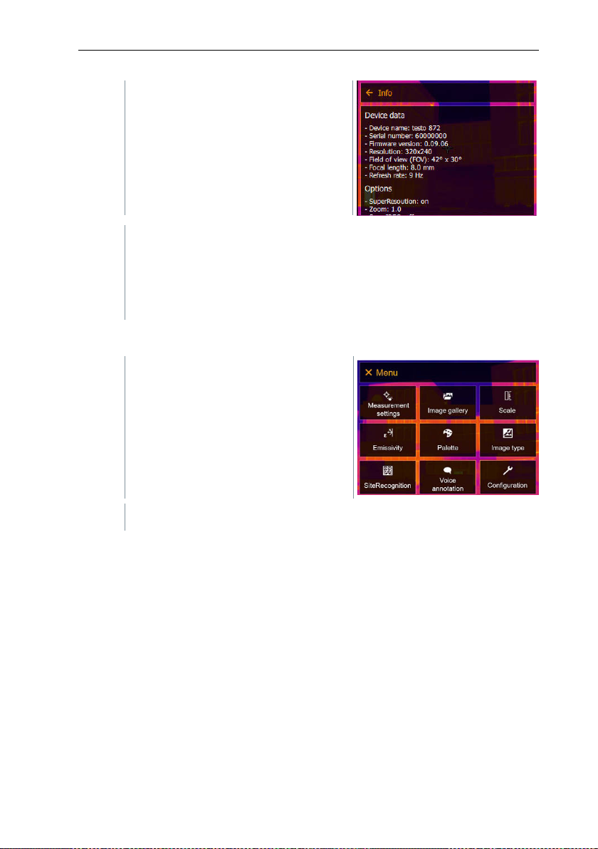
The following information is displayed:
1
Open the Menu.
2
Select Configuration (joystick or touchscreen).
Info opens.
• Device data (e.g. serial number, device name, firmware version)
• Options
• Measuring functions
• Radio
11.10.11 Certificates
72
Page 73
11 Performing the measurement
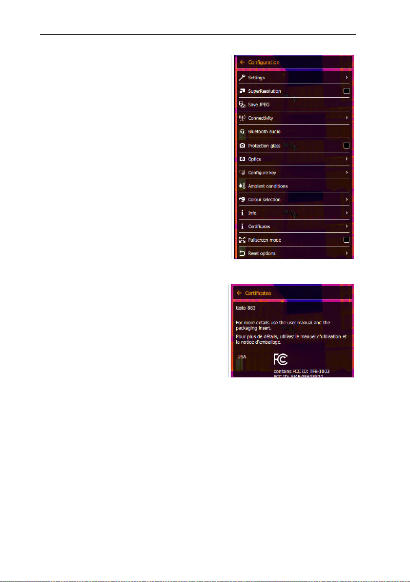
3
Select Certificates (joystick or touchscreen).
Stored certificates are displayed.
Configuration opens.
Certificates opens.
73
Page 74
11 Performing the measurement
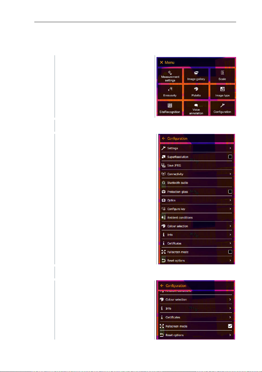
1
Open the Menu.
2
Select Configuration (joystick or touchscreen).
3
Select Fullscreen mode (joystick or touchscreen).
11.10.12 Fullscreen mode
The scale and the quick select button function indicator can be hidden.
Configuration opens.
Fullscreen mode opens.
74
Page 75
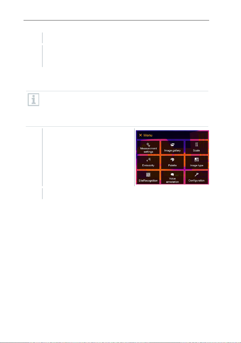
Fullscreen mode is enabled (✔) or disabled.
When Fullscreen Mode is activated, the scale and icon for the quick
1
Open the Menu.
2
Select Configuration (joystick or touchscreen).
select button are hidden. When a key is pressed, these elements are
displayed briefly.
11.10.13 Reset options
11.10.13.1 Reset counter
Aft
er a reset, the consecutive numbering of images starts again from
the beginning. When saving images, already saved images with the
same number are overwritten!
Back up all saved images before resetting the counter to prevent
possible overwriting.
11 Performing the measurement
75
Page 76
11 Performing the measurement
3
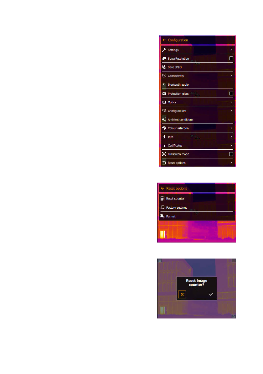
Select Reset options (joystick or touchscreen).
4
Select Reset counter.
5
Press to confirm or press X to cancel the process.
Configuration opens.
Reset options opens.
Reset image counter? is displayed.
76
Page 77
11 Performing the measurement
1
Open the Menu.
2
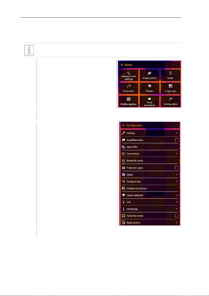
Select Configuration (joystick or touchscreen).
3
Select Reset options (joystick or touchscreen).
11.10.13.2 Factory settings
The instrument settings can be reset to the factory settings.
Time/date, country settings and counter are not reset.
Configuration opens.
77
Page 78
11 Performing the measurement
4
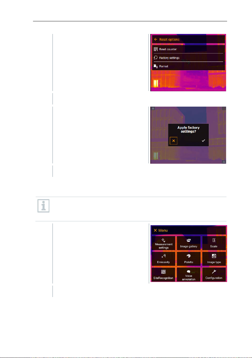
Select Factory settings.
5
Press to confirm or press X to cancel the process.
1
Open the Menu.
2
Select Configuration (joystick or touchscreen).
Reset options opens.
Apply factory settings? is
displayed.
11.10.13.3 Formatting
The image memory can be formatted.
When for
saved images before formatting to prevent loss of data.
Formatting does not reset the counter.
matting, all images saved in the memory are lost. Back up all
78
Page 79
11 Performing the measurement
3
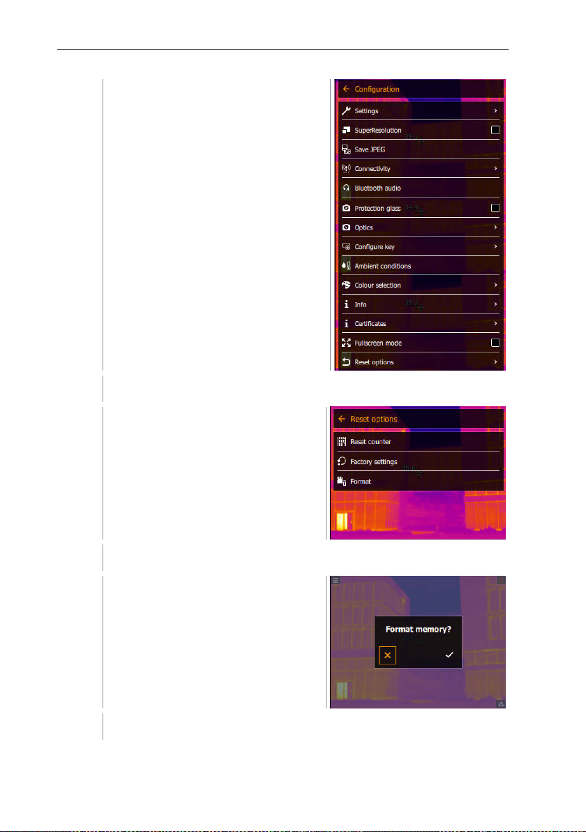
Select Reset options (joystick or touchscreen).
4
Select Format.
5
Press to confirm or press X to cancel the process.
Configuration opens.
Reset options opens.
Format memory? is displayed.
79
Page 80
12 Maintenance
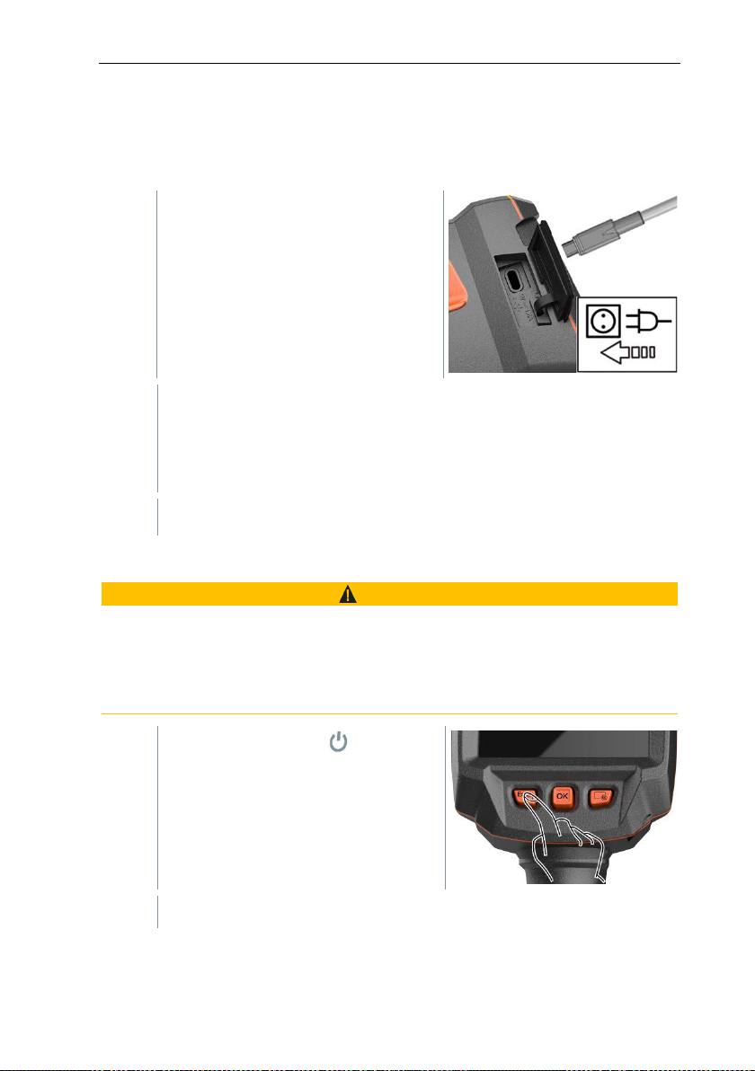
1
Open the cover of the interface
terminal.
2
Connect the charging cable to the
USB-C port.
3
Connect the mains unit to a mains
4
Switch on the instrument to call up the charge status.
Serious risk of injury to
> There is a risk of explosion if the battery is replaced with one that is the wrong
type.
> Dispose of spent/faulty batteries in accordance with the relevant legal
specifications.
1
12 Maintenance
12.1 Charging the rechargeable battery
socket.
The charging process starts.
If the battery has been completely drained, the charging time is
approx. 6 hours with the mains unit supplied.
12.2 Changing the rechargeable battery
WARNING
the user and/or destruction of the instrument
The charge status is not displayed while the instrument is switched off.
- Press and hold down until the
progress bar on the display is
complete.
The display goes off.
80
Page 81
12 Maintenance
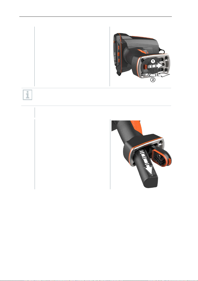
2
Pull back the unlocking button to
The rechargeable battery is released and slides out a little from the
rechargeable battery slot.
3
Pull the rechargeable battery
open the battery compartment cover
on the bottom of the handle.
The rechargeable battery is no longer secured and may fall out of the
battery compartment. Make sure that you always open the battery
compartment cover with it facing upwards.
completely out of the battery
compartment.
81
Page 82
12 Maintenance
4
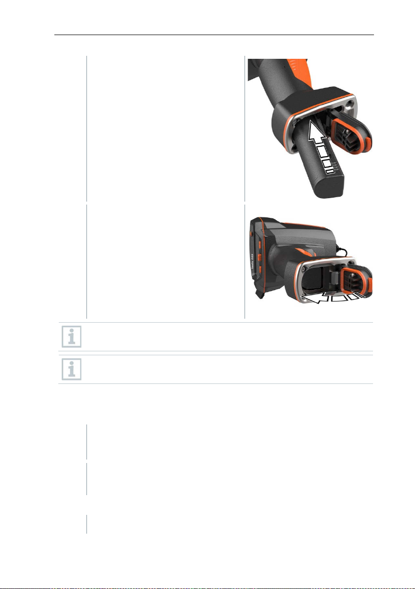
Push the new battery all the way into
5
Close the battery compartment cover
- The interface terminal is closed.
1
- Rub down the surface of the instrument with a damp cloth. Use mild
1
If the lens is dirty, clean it with a cotton bud.
the rechargeable battery slot until it
is flush with the bottom of the handle.
and secure with the unlocking button.
There is a tripod socket bushing on the base of the imager. A standard
tripod can be used to mount the imager.
The supplied carrying strap can be attached to the tripod socket
bushing.
12.3 Cleaning the instrument
Cleaning the instrument housing
- The battery compartment is closed.
household cleaning agents or soapy water for this.
Cleaning the lens
82
Page 83

12 Maintenance
1
If the display is dirty, clean it with a cleaning cloth (e.g. microfibre
cloth).
1
Larger dust particles can be removed with a clean optical cleaning
brush (available from specialized photo supplies).
2
Use a lens cleaning cloth for slight contamination. Do not use rubbing
alcohol!
1
Download firmware: Firmware-testo-883.exe.
2
Unzip file: double-click on the .exe file.
The rechargeable battery is fully charged or the camera is connected to
1
Connect the computer to the camera with the USB cable.
2
Switch on the camera.
IRSoft is activated.
1
Select Menu -> Configuration.
Cleaning the display
Cleaning the protective glass
12.4 Firmware update
The current firmware version is available at www.testo.com.
There are two options available:
• Performing an update using IRSoft or
• Performing an update with the thermal imager
Downloading firmware
12.4.1 Performing an update using IRSoft
12.4.1.1 Preparing the camera
FW_T883_Vx.xx.bin is stored in the selected folder.
the mains adapter.
Firmware is fully loaded.
12.4.1.2 Performing an update
83
Page 84

12 Maintenance
2
Click on Configure thermal imager.
3
Select Instrument settings -> Firmware Update -> OK.
4
Select Open.
In certain circumstances, the camera reports: Firmware update
The rechargeable battery is fully charged or the camera is connected to
1
Switch on the camera.
2
Open the cover of the interface.
3
Connect the computer to the camera with the USB cable.
1
Copy the FW_T883_Vx.xx.bin file to the removable medium using
2
Eject the removable medium.
3
Disconnecting the USB connection.
The Camera settings window is opened.
FW_T883_Vx.xx.bin is displayed.
Firmware update is performed.
Thermal imager is automatically restarted. Update complete.
finished. Please restart the device. A restart is not performed.
Action:
- After 10 seconds, switch off the camera; switch back on again after 3
seconds.
The current firmware version is displayed.
12.4.2 Performing an update with the camera
12.4.2.1 Preparing the camera
the mains adapter.
The camera is displayed as a removable medium in Windows Explorer.
12.4.2.2 Performing an update
drag & drop.
84
Page 85

4
Switch off camera.
5
Switch on the camera: an update is performed.
6
Observe the progress bar.
Update complete. The current firmware version is displayed.
12 Maintenance
85
Page 86

13 Technical data
Thermal sensitivity (NETD)
<= 40 mK
± 3° for readings from -30 °C to -20 °C
± 2% for readings from 100 °C to +650 °C
Measuring range 1 from -30 °C to +100 °C
Measuring range 2 from 0 °C to +650 °C
Field of view (FOV) with
wide-angle lens
Geometric resolution (iFOV)
with wide-angle lens
Focusing, wide-angle lens
manual, 0.1 m to infinity
Field of view (FOV) with
telephoto lens
Geometric resolution (iFOV)
with telephoto lens
27 Hz or 9 Hz, depending on export
restrictions
Focusing, telephoto lens
manual, 0.5 m to infinity
Spectral range
7.5 - 14 µm
Image sensor resolution,
visual
Minimum focusing distance,
visual
Display
8.9 cm (3.5") TFT, QVGA (320 x 240 pixels)
Digital zoom
2x / 4x
Display options
• Infrared image
13 Technical data
13.1 Optical data
Feature Values
Infrared resolution 320 x 240
SuperResolution 640 x 480 pixels
Measurement accuracy
Measuring ranges
Image refresh rate
± 2° for readings from -20 °C to +100 °C
30° x 23°
1.7 mrad
12° x 9°
0.7 mrad
3 MP
< 0.5 m
13.2 Image presentation
Feature Values
86
• Real image
Page 87
Colour palettes
11 options:
• Blue/red
Communication
Thermography App
Communication with PC
(IRsoft)
Communication with
headset
Bluetooth Low Energy:
- testo 770-3 clamp meter
Feature
Values
Up to 5 selectable individual measuring
isotherm
Temperature scaling
Automatic, manual or testo ScaleAssist
Manual: Input of the solar radiation value
Manual: Input of ambient humidity and
must be ordered separately)
• Grey
• Inverted grey
• Iron HT
• Cold-hot
• Humidity
• Iron
• Rainbow
• Rainbow HC
• Sepia
• Testo
13.3 Data interfaces
Feature Values
WLAN IEEE 802.11b/g/n
USB-C jack; USB 2.0
13 Technical data
Bluetooth 4.2
Communication with
external probes
- testo 605i humidity probe
13.4 Measuring functions
Analysis function
Solar mode
Humidity mode
points, hot/cold spot detection, Delta T, area
measurement (min/max on area), alarms,
temperature
or
Automatic data transfer of testo 605i
thermohygrometer via Bluetooth (instrument
87
Page 88

13 Technical data
Manual: Input of current, voltage or power
must be ordered separately)
Reflected temperature
Manual input
0.01-1.0; manual input, material selection or
testo ε-Assist
Digital camera
Yes
Touch operation
yes (capacitive touch display)
Fullscreen mode
Yes
Save JPEG
yes, optionally with date/time
Video streaming
• USB
Laser (not available in USA,
Japan, China)
Laser marker (laser class 2, 635 nm)
Interfaces
USB 2.0 (USB-C jack)
WLAN Connectivity
Communication with the testo Thermography
App; wireless module BT/WLAN
Bluetooth
Headset for voice annotations; transfer of
testo 770-3 clamp meter (optional)
Tripod socket
for carrying strap (included in the scope of
delivery) or a photo tripod with UNC thread
or
Electrical mode
Automatic transmission of data from the testo
770-3 clamp meter via Bluetooth (instrument
IFOV warner Yes
Emissivity
13.5 Imager features
Feature Values
• WLAN with testo Thermography App
• Non-radiometric
88
readings from testo 605i thermohygrometer,
Page 89
13 Technical data
• .jpg
Internal memory 2.8 GB,
> 2000 images (without SuperResolution)
Fast-charging Li-ion battery, replaceable on
site (6600 mAh / 3.7 V)
Operating time
5.5 h at 20 °C ambient temperature
Mains operation
With mains unit supplied
In the instrument (via supplied mains unit) / in
charging station (optional)
Charging time
approx. 6 h via mains unit
USB port
5V 1.8 A*
Operating temperature
-15 to 50 °C
Storage temperature
-30 to 60 °C
Humidity
20 to 80 %RH; non-condensing
13.6 Image storage
Feature Values
• .bmt
• Can export as
.bmp
File format
Memory capacity
.jpg
.png
.csv
.xls
• Via testo IR-Soft
13.7 Audio functions
Feature Values
Sound recording / playback via headset (included in the scope of delivery)
Recording duration 1 min per image
13.8 Power supply
Feature Values
Battery type
Charging options
* Direct current
13.9 Ambient conditions
Feature Values
89
Page 90
13 Technical data
Battery charging
temperature range
0 °C to +45 °C
Housing protection class
IP 54
Vibration resistance
2g according to IEC 60068-2-6
WEEE
2012/19/EU
RoHS
2011/65/EU + 2015/863
You can find the EU declaration of conformity on the Testo website,
13.10 Physical features
Feature Values
Product/housing material PC - ABS
Product colour
Weight
Dimensions 171 x 95 x 236 mm
Display illumination
black
827 g
bright / normal / dark
13.11 Standards, tests
Feature Values
EMC 2014/30/EU
RED 2014/53/EU
REACH 1907/2006
www.testo.com, under the product-specific downloads.
90
Page 91
14 Questions and answers
Error! Memory full! is
displayed.
Insufficient memory available: Transfer images
to the PC or delete.
Error! Permissible
exceeded! is displayed.
Switch off the camera, allow the instrument to
ambient temperature.
~ is displayed before a value.
Value is outside the measuring range:
accuracy.
--- or +++ is displayed
instead of a value.
Value is outside the measuring range and the
extended display range.
xxx is displayed instead of a
value.
Value cannot be calculated: Check parameter
settings for plausibility.
Automatic zeroing (audible
frequently.
Camera is still in its warm-up period (takes
Battery charging station 5 V, 2 A
0554 8801
Spare rechargeable battery
0554 8831
Additional markers for ε-Assist function (10 off)
0554 0872
Emission tape
0554 0051
25 °C, 50 °C
ISO calibration certificate: calibration points at 0 °C,
100 °C, 200 °C
0520 0490
ISO calibration certificate: Freely selectable calibration
points in the range -18 °C to 250 °C
0520 0495
14 Questions and answers
Question Possible cause / solution
instrument temperature
cool down and observe the permissible
extended display range with no guarantee of
“click” and brief image
freeze) is carried out very
If we have not been able to answer your question, pleas
approx. 90 seconds): Wait until the warm-up
period has passed.
e contact your dealer or
Testo Customer Service. You will find contact details on the back of this
document
15 Accessories
or on the website
Description Order no.
ISO calibration certificate: calibration points at 0 °C,
0520 0489
91
Page 92

0970 8830 en
Test Equipment Depot - 800.517.8431 - 5 Commonwealth Ave, MA 01801
TestEquipmentDepot.com
02
 Loading...