

Page 1
99 Washington Street
Melrose, MA 02176
Phone 781-665-1400
Toll Free 1-800-517-8431
Visit us at www.TestEquipmentDepot.com
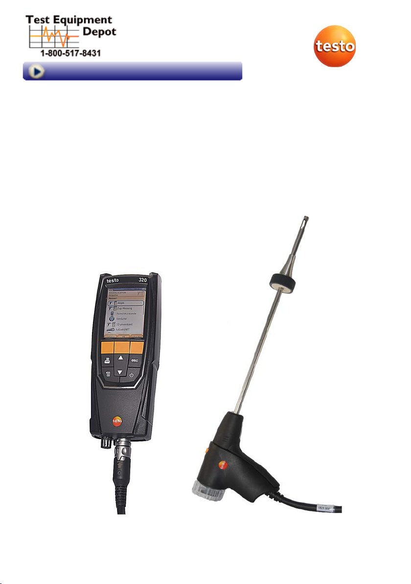
testo 320 · Flue gas analyzer
Instruction manual
Page 2

2
Page 3

1 Contents
Pos: 1 /TD/Überschriften/1. Inhalt @ 0\mod_117758781707 0_79.docx @ 1243 @ 1 @ 1
1 Contents
1 Contents ................................................................................................... 3
2 Safety and the environment .................................................................... 6
2.1. About this document ........................................................................ 6
2.2. Ensure safety ................................................................................... 7
2.3. Protecting the environment .............................................................. 8
3 Specifications .......................................................................................... 9
3.1. Use .................................................................................................. 9
3.2. Technical data ............................................................................... 10
3.2.1. Examinations and licenses ............................................................................ 10
3.2.2. Bluetooth® module (option) ............................................................................ 10
3.2.3. Declaration of Conformity .............................................................................. 12
3.2.4. Measurement ranges and resolution .............................................................. 13
3.2.5. Accuracy and response time .......................................................................... 13
3.2.6. Other instrument data .................................................................................... 15
4 Product description ............................................................................... 16
4.1. Case 0516 3300 (accessory) ......................................................... 16
4.1.1. Bottom level view ........................................................................................... 16
4.1.2. Top level view ................................................................................................ 17
4.2. Case 0516 3301 (accessory) ......................................................... 18
4.2.1. Bottom level view ........................................................................................... 18
4.2.2. Middle level view ............................................................................................ 19
4.2.3. Top level view ................................................................................................ 20
4.3. Measuring instrument .................................................................... 21
4.3.1. Front view ...................................................................................................... 21
4.3.2. Keypad .......................................................................................................... 22
4.3.3. Display ........................................................................................................... 22
4.3.4. Instrument connections .................................................................................. 23
4.3.5. Condensate outlet and interfaces .................................................................. 24
4.3.6. Rear view ....................................................................................................... 25
4.3.7. Components .................................................................................................. 26
4.4. Compact flue gas probe ................................................................ 27
4.5. Modular flue gas probe .................................................................. 27
3
Page 4

1 Contents
5
First steps .............................................................................................. 28
5.1. Commissioning ............................................................................. 28
5.2. Getting to know the product .......................................................... 28
5.2.1. Mains operation ............................................................................................. 28
5.2.2. Connecting probes ......................................................................................... 28
5.2.3. Switching on .................................................................................................. 29
5.2.4. Calling up the function ................................................................................... 30
5.2.5. Entering values .............................................................................................. 30
5.2.6. Printing/saving data ....................................................................................... 31
5.2.7. Saving data to the clipboard (temporary memory) ......................................... 32
5.2.8. Confirming an error message ........................................................................ 32
5.2.9. Switching off .................................................................................................. 32
5.3. Address/Location .......................................................................... 32
5.4. Measurement records ................................................................... 35
5.5. Instrument diagnosis ..................................................................... 35
6 Using the product ................................................................................. 36
6.1. Performing settings ....................................................................... 36
6.1.1. Assigning the right function key ..................................................................... 36
6.1.2. Instrument settings ........................................................................................ 36
6.1.2.1. Measurement view .......................................................................... 36
6.1.2.2. Alarm limits ...................................................................................... 38
6.1.2.3. Units ................................................................................................ 38
6.1.2.4. Date / time ....................................................................................... 39
6.1.2.5. Energy management ....................................................................... 39
6.1.2.6. Display brightness ........................................................................... 39
6.1.2.1. Choose measurement type ............................................................. 40
6.1.2.2. Printer ............................................................................................. 40
6.1.2.3. Bluetooth® ....................................................................................... 41
6.1.2.4. Language ........................................................................................ 41
6.1.2.5. Country version ............................................................................... 41
6.1.2.6. Password protection ........................................................................ 42
6.1.3. Sensor settings .............................................................................................. 42
6.1.3.1. O2 reference .................................................................................... 42
6.1.3.2. Sensor protection ............................................................................ 43
6.1.3.3. Recalibration/adjustment ................................................................. 43
6.1.4. Fuels .............................................................................................................. 44
4
Page 5

1 Contents
6.2.
Measuring ...................................................................................... 45
6.2.1. Preparing for measurement ........................................................................... 45
6.2.1.1. Testing for leaks .............................................................................. 45
6.2.1.2. Zeroing phases ................................................................................ 45
6.2.1.3. Using flue gas probe ........................................................................ 46
6.2.1.4. Measurement view .......................................................................... 47
6.2.1.5. Setting the location and fuel ............................................................ 47
6.2.2. Flue gas ......................................................................................................... 47
6.2.3. Draught measurement ................................................................................... 49
6.2.4. External micro pressure probe ....................................................................... 49
6.2.5. Average ......................................................................................................... 50
6.2.6. BImSchV ........................................................................................................ 51
6.2.7. CO undiluted .................................................................................................. 52
6.2.8. Smoke number/HCT ...................................................................................... 52
6.2.9. Pressure ........................................................................................................ 53
6.2.10. Differential temperature ................................................................................. 54
6.2.11. O2 air ............................................................................................................. 54
6.2.12. Gas flow rate .................................................................................................. 55
6.2.13. Oil flow ........................................................................................................... 55
6.2.14. Ambient CO ................................................................................................... 56
6.2.15. CO2 ambient .................................................................................................. 57
6.2.16. Leak detection ............................................................................................... 58
6.3. Transferring data ........................................................................... 59
6.3.1. Report printer ................................................................................................. 59
6.3.2. PC / Pocket PC .............................................................................................. 59
7 Maintaining the product ........................................................................ 60
7.1. Cleaning the measuring instrum ent ............................................... 60
7.2. Replacing the rechargeable battery ............................................... 60
7.3. Charging the battery ...................................................................... 62
7.4. Replacing sensors ......................................................................... 62
7.5. Recalibrating/adjusting se ns ors ..................................................... 63
7.6. Modular flue gas probe .................................................................. 63
7.6.1. Cleaning the flue gas ducts ............................................................................ 63
7.6.2. Replacing the probe module .......................................................................... 63
7.6.3. Replacing the thermocouple .......................................................................... 64
7.6.4. Checking the particle filter .............................................................................. 64
7.6.5. Replacing the particle filter: ............................................................................ 64
7.7. Compact flue gas probe ................................................................ 65
7.7.1. Cleaning the probe shaft ................................................................................ 65
7.7.2. Replacing the thermocouple .......................................................................... 65
7.7.3. Checking the particle filter .............................................................................. 67
7.7.4. Replacing the particle filter ............................................................................. 68
7.8. Condensate container ................................................................... 68
8 Tips and assistance ............................................................................... 70
8.1. Questions and answers ................................................................. 70
8.2. Accessories and spare parts ......................................................... 70
8.3. Updating the instrument software .................................................. 74
Pos: 2 /TD/--- Seitenwechsel --- @ 0\mod_1173774430601_0.docx @ 283 @ @ 1
5
Page 6
2 Safety and the environment
Pos: 3 /TD/Überschriften/2. Sicherheit und Umwelt @ 0\mod_1 173774719351_79.docx @ 292 @ 1 @ 1
2 Safety and the environment
Pos: 4 /TD/Überschriften/2.1 Zu diesem Dokument @ 0\mod_11737 75252351_79.docx @ 346 @ 2 @ 1
2.1. About this document
Pos: 5 /TD/Sicherheit und Umwelt/Zu diesem Dokument/Ver wendung/Verwendung (Standard) @ 0\mod_1173775068554_ 79.docx @ 337 @ 5 @ 1
Use
> Please read this documentation t hrough carefully and
familiarize yourself with the product before putting it to use. Pay
particular attention to the safety instructions and warning advice
in order to prevent injuries and damage to the products.
> Keep this document to hand so that you can refer to it when
necessary.
> Hand this documentation on to any subsequent users of the
Pos: 6 /TD/Sicherheit und Umwelt/Zu diesem Dokument/Sy mb ol e und Schreibkonventionen/Tabellenkopf War nhinweise @ 2\mod_1207645198296_79.docx @ 14334 @ 5 @ 1
product.
Warnings
Always pay attention to informati on that is marked by the following
warnings with warning pictograms. Implement the specified
precautionary measures.
Representation Explanation
Pos: 7 /TD/Sicherheit und Umwelt/Zu diesem Dokument/Sy mbole und Schreibkonventionen/Warnhinweis WARNUN G @ 2\mod _120 7646966234_79.docx @ 14398 @ @ 1
Pos: 8 /TD/Sicherheit und Umwelt/Zu diesem Dokument/Sy mb ol e und Schreibkonventionen/Warnhinweis VORSICHT @ 2\mo d_12 07651416515_79.docx @ 14416 @ @ 1
Pos: 9 /TD/Sicherheit und Umwelt/Zu diesem Dokument/Sy mb ol e und Schreibkonventionen/Warnhinweis ACHTUNG (Produk tschaden) @ 2\mod_1207651536812_79.docx @ 14434 @ @ 1
WARNING
CAUTION
NOTICE
Pos: 10 /TD/Sicherheit und Umwelt/Zu diesem Dokument/Sy m bo le und Schreibkonventionen/Tabellenkopf Symbole un d Schreibkonv. @ 2\mod_1207652481703_79.docx @ 14452 @ 5 @ 1
Indicates potential serious inju ries
indicates potential minor injuries
indicates circumstances that may lea d to
damage to the products
Pos: 11 /TD/Sicherheit und Umwelt/Zu diesem Dokument/Sy m bo le und Schreibkonventionen/Symbole und Schreibkonv. [ Standard_klein] @ 2\mod_1207652632140_79.docx @ 14470 @ @ 1
Symbols and writing standards
Represen-
Explanation
tation
Note: Basic or further information.
1. ...
Pos: 12 /TD/Sicherheit und Umwelt/Zu diesem Dokument/Sy m bo le und Schreibkonventionen/Schreibkonv. [OK] @ 2\ mod_1207655489218_79.docx @ 14506 @ @ 1
2. ...
> ... Action: a step or an optional step.
- ... Result of an action.
Action: more steps, the sequence must be followed.
[OK] Control keys of the instrument or butt ons of the
program interface.
6
Page 7

Pos: 13 /TD/Überschriften/2.2 Sicherheit gewährl eisten @ 0\mod_1173780783960_79.docx @ 366 @ 2 @ 1
2.2. Ensure safety
Pos: 14 /TD/Sicherheit und Umwelt/Sicherheit gewähr lei s ten/Produkt bestimmungsgemäß verwenden @ 0\mod_1173 781261848_79.docx @ 386 @ @ 1
> Only operate the product properly, for its intended purpose and
within the parameters specified in the technical data. Do not
Pos: 15 /TD/Sicherheit und Umwelt/Sicherheit gewähr lei s ten/Gerät bei Beschädigungen nicht in Betrieb neh men @ 0\ mod_1186985945375_79.docx @ 2252 @ @ 1
use any force.
> Do not operate the instrument if there are signs of damage at
Pos: 16 /TD/Sicherheit und Umwelt/Sicherheit gewähr lei s ten/Keine Messung an spannungsführenden Teilen @ 0\ mod_1175692564164_79.docx @ 592 @ @ 1
the housing, mains unit or feed lines .
> Do not perform contact measurements on non-insulated, live
Pos: 17 /TD/Sicherheit und Umwelt/Sicherheit gewähr lei s ten/testo 320/testo 320 Kurzzeitmessung @ 13\mod_137 0246144153_79.docx @ 162574 @ @ 1
parts.
> The testo 320 is not suitable for long-t erm measurements and
Pos: 18 /TD/Sicherheit und Umwelt/Sicherheit gewähr lei s ten/Nicht mit Lösungsmitteln lagern @ 0\mod_1175692 375179_79.docx @ 583 @ @ 1
should not be used as a safety (alarm) instrument.
> Do not store the product together with solvents. Do not use any
Pos: 19 /TD/Sicherheit und Umwelt/Sicherheit gewähr lei s ten/Nur beschriebene Wartungsarbeiten durchf ühren @ 0\mod_1175692705195_79.docx @ 601 @ @ 1
desiccants.
> Carry out only the maintenance and re pair work on this
instrument that is described in the documentation. Follow the
prescribed steps exactly. Use only original spare parts from
Pos: 20 /TD/Sicherheit und Umwelt/Sicherheit gewähr lei s ten/testo 350/testo 350 Sicherheit @ 5\mod_1261385 8457 35_79.docx @ 53306 @ @ 1
Testo.
> Any further or additional work mus t only be carried out by
authorised personnel. Testo will otherwise refuse to accept
responsibility for the proper functi oning of the measuring
Pos: 21 /TD/Sicherheit und Umwelt/Sicherheit gewähr lei s ten/Nur in geschlossenen, trockenen Räumen betreibe n @ 0\mod_1186985797828_79.docx @ 2243 @ @ 1
instrument after repair and for the validity of certifications.
> Only use the device in closed, dr y rooms and protect it from rain
Pos: 22 /TD/Sicherheit und Umwelt/Sicherheit gewähr lei s ten/Temperaturangaben auf Sonden/Fühlern @ 0\mod_1 175693293070_79.docx @ 610 @ @ 1
and moisture.
> Temperatures given on probes/sensors relate only to the
measuring range of the sensors. Do not expose handles and
feed lines to any temperatures in excess of 70 °C unless they
Pos: 23 /TD/Sicherheit und Umwelt/Sicherheit gewähr lei s ten/testo 320/testo 320 Sichtbarer Schaden @ 13\mod_1 370249752584_79.docx @ 162608 @ @ 1
are expressly permitted for higher temperatures.
> The testo 320 must be checked before commissioning for
any visible damage. Do not commission the testo 320 if
there are signs of damage on the housing, mains unit or
Pos: 24 /TD/Sicherheit und Umwelt/Sicherheit gewähr lei s ten/vor Ort gültige Sicherheitsbestimmungen be ac hten @ 0\mod_1186997107328_79.docx @ 2298 @ @ 1
supply lines. Electrical risk.
> The objects to be measured or the measur ement environment
may also pose risks: Note the safety regulations valid in your
Pos: 25 /TD/Sicherheit und Umwelt/Sicherheit gewähr leisten/Option Bluetooth testo 330 @ 7\mod_12814223209 10_79.docx @ 68203 @ 5 @ 1
area when performing the measurements.
2 Safety and the environment
7
Page 8

2 Safety and the environment
For products with Bluetooth® (optional)
Changes or modifications that have been made without the explicit
consent of the responsible approval authority, may cause the
retraction of the type approval.
Data transfer may be disturbed by eq uipment that uses the same
ISM-band, e.g. WLAN, microwave ovens, Z i gB ee.
The use of radio communication link s is not permitted, among
others, in aeroplanes and hospitals . For this reason the following
points must be ensured before entering:
> Switch off the device:
> Isolate the device from any external power sources (mains
Pos: 26 /TD/Überschriften/2.3 Umwelt schützen @ 0\mod_11 73780843645_79.docx @ 375 @ 2 @ 1
2.3. Protecting the environment
Pos: 27.1 /TD/Sicherheit und Umwelt/Umwelt schützen/ Akkus/Batterien entsorgen @ 0\mod_1175693637007_79. docx @ 619 @ @ 1
cable, external rechargeable batteries, ...).
> Dispose of faulty rechargeable batt eries/spent batteries in
Pos: 27.2 /TD/Sicherheit und Umwelt/Umwelt schützen/ Produkt entsorgen @ 0\mod_1173780307072_79.doc x @ 357 @ @ 1
accordance with the valid legal specifications.
> At the end of its useful life, send the produc t to the separate
collection for electric and electronic devices (observe local
Pos: 28 /TD/Überschriften/3. Leistungsbeschrei bung @ 0\mod_1173774791554_79.docx @ 301 @ 1 @ 1
regulations) or return the product to Testo for disposal.
8
Page 9
3 Specifications
Pos: 29 /TD/Überschriften/3.1 Verwendung @ 0\mod_1176211 016437_79.docx @ 695 @ 2 @ 1
3.1. Use
Pos: 30 /TD/Leistungsbeschreibung/Verwendung/ testo 3xx/testo 320_Verwendung @ 12\mod_1334143881206_ 79.docx @ 116769 @ @ 1
The testo 320 is a handheld measuring d ev ice for the professional
flue gas analysis of combustion pla nts:
• Small combustion plants (burning oil, gas, wood, coal)
The solid fuel measurement adapter (0600 9765) is
required for measurements on solid fuel systems. The
adapter protects the measuring instrument from harmful
substances (dust, organic compou nds , etc.).
• Low-temperatu re and condensing boilers
• Gas water heaters
These systems can be adjusted using the testo 320 and checked
for compliance with the applicable limit values.
The following tasks can also be carried out with the testo 320:
• Regulating the O2, CO and CO2 values in combustion plants
for the purpose of ensuring optimal op eration.
• Draught measur ement.
• Measuring and r egulating the gas flow pressure in gas water
heaters.
• Measuring and optimising the flow and return temperatures of
heating systems.
• Ambient CO meas urement (only possible with addit i onal
ambient CO probe 0632 3331).
• Ambient CO meas urement (only possible with addit i onal
ambient CO probe 0632 1240).
• Detection of CH4 ( methane) and C3H8 (propane) (only possible
Pos: 31 /TD/Überschriften/3.2 Technische Daten @ 0\mod_ 1176 211088437_79.docx @ 704 @ 2 @ 1
with additional gas leak probe 0632 3370).
The Bluetooth
is type approved.
®
option may only be operated in countries in which it
3 Specifications
9
Page 10

3 Specifications
3.2. Technical data
Pos: 32 /TD/Leistungsbeschreibung/Technische Dat en/testo 320/Zulassungen testo 320 @ 12\mod_13334594849 98_79.docx @ 115437 @ 335 @ 1
3.2.1. Examinations and licenses
As declared in the certificate of conformity, this product complies
with Directive 2014/30/EC.
This product is TÜV-tested in compliance with 1. BImSchV. The
sensors 0393 0105 (CO, H2-compensated), 0393 0003 (O2),
temperature and pressure are TÜ V-tested in accordance with EN
50379 part 2.
The measuring cell 0393 0053 (CO, not H2-compensated) is TÜVtested as per EN 50379 part 3.
This product is EMC-tested as per DIN EN 61326-1.
For official measurements in accor dance with 1. BImSchV
(chimney sweeps), the measuring ins trument must be checked
every six months by a technical testing body of the Guild of Master
Chimney Sweeps or another testing b ody recognised by the
authorities.
3.2.2. Bluetooth® module (option)
• Bluetooth® type: BlueGiga WT 11 / WT 11i-A (from
October 2013)
• Bluetooth® product note: WT11
• Bluetooth
B017633 (WT11i-A)
• Bluetooth® company: 10274
®
identification: B017401 (WT 11) /
10
Certification
Belgium (BE), Bulgaria (BG), Denmark (DK), Germany (DE),
Estonia (EE), Finland (FI), France (FR), Greece (GR), Ireland (IE),
Italy (IT), Latvia (LV), Lithuania ( LT), Luxembourg (LU), Malta (MT),
Netherlands (NL), Austria (AT), Poland (PL), Portugal (PT),
Romania (RO), Sweden (SE), Slovakia (SK), Slovene (SI), Spain
(ES), Czech Republic (CZ), Hungary (HU), United Kingdom (GB),
Republic of Cyprus (CY).
EFTA countries
Iceland, Liechtenstein, Nor way and Switzerland.
Other countries
USA, Canada, Turkey, Colombia, El Salvador, Ukraine, Venezuela,
Ecuador, Australia, New Zealand, Bolivia, Dominican Republic,
Peru, Chile, Cuba, Costa Rica, Nicaragua, Korea
Page 11

3 Specifications
I
nformation of the FCC (Federal Communications
Commission)
This device fulfils part 15 of the FCC -guidelines. Commissioning is
subject to the two following condit ions: (1) This device must not
generate any dangerous interferences and (2) this device must be
able to receive interferences, even if these could have undesired
effect on the operation.
Changes
The FCC demands that the user is to be info r med that with any
changes and modifications to t he device, which have not been
explicitly approved by testo AG, the right of the user to use this
device will become null and void.
Test Equipment Depot - 800.517.8431 - 99 Washington Street Melrose, MA 02176
TestEquipmentDepot.com
11
Page 12
3 Specifications
Pos: 33 /TD/Leistungsbeschreibung/Technische Dat en/testo 320/Konformitätserklärung testo 320 @ 11\ mod_1327330430653_79.docx @ 104226 @ 3 @ 1
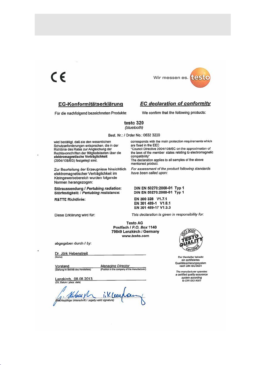
3.2.3. Declaration of Conformity
12
Page 13
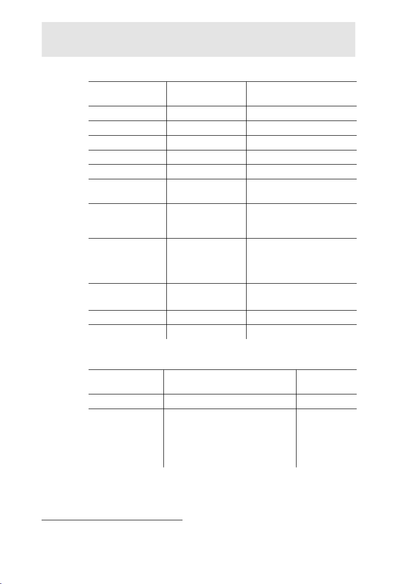
Pos: 34 /TD/Leistungsbeschreibung/Technische Dat en/testo 320/Messbereiche_Genauigkeiten tes to3 20 @ 11\mod_1327415011913_79.docx @ 105453 @ 33 @ 1
3.2.4. Measurement ranges and resolution
Measurement
parameter
O2 0 to 21 Vol.% 0.1 vol.%
CO 0...4000 ppm 1 ppm
CO, H2-comp.
COlow, H2-comp. 0 to 500 ppm 0.1 ppm
Draught1 -9.99 to 40.00 hPa 0.01 hPa
Fine draught1
ΔP (only with gas
pressure set 0554
1203)
Fine pressure1
(only with gas
pressure set 0554
1203)
temperature -40 to 1200°C 0.1°C (-40.0 to 999.9°C)
Efficiency 0 to 120 % 0.1 %
Flue gas loss 0 to 99.9 % 0.1 %
Measuring range Resolution
0 to 8000 ppm 1 ppm
-9.999 hPa to
0.001 hPa
+40.000 hPa
0 to 300 hPa 0.1 hPa
0 to 300 hPa 0.01 hPa
1°C (from 1000°C)
3 Specifications
3.2.5. Accuracy and response time
Measurement
Accuracy
parameter
O2 ±0.2 vol.% < 20 s
CO
±20 ppm (0 to 400 ppm)
±5% of meas. val. (401 to 2000
ppm)
±10% of meas. val. (2001 to
4000 ppm)
1
Depending on the country version
13
Response
time (t
)
90
< 60 s
Page 14

3 Specifications
2
2
Measurement
Accuracy
parameter
CO, H2-comp.
±10 ppm or ±10% of meas. val.
(0 to 200 ppm)
±20 ppm or ±5% of meas. val.
2
(201 to 2000 ppm)
±10% of meas. val. (2001 to
8000 ppm)
COlow, H2-comp. ±2 ppm (0 to 39.9 ppm)
±5% of meas. val. (rest of range)
Draught1
±0.02 ppm or ±5% of meas. val.
2
(-0.50 to 0.60 hPa)
± 0.03 hPa (0.61 to 3.00 hPa)
±1.5% of meas. val. (3.01 to
40.00 hPa)
Fine draught1
±0.02 ppm or ±5% of meas. val.
(-0.50 to 0.60 hPa)
± 0.03 hPa (0.61 to 3.00 hPa)
±1.5% of meas. val. (3.01 to
40.00 hPa)
ΔP (only with gas
pressure set 0554
1203)
± 0.5 hPa (0.0 to 50.0 hPa)
±1% of meas. val.
(50.1 to 100.0 hPa)
±1.5% of meas. val. (rest of
range)
Fine pressure1
(only with gas
pressure set 0554
1203)
± 0.5 hPa (0.0 to 50.0 hPa)
±1% of meas. val.
(50.1 to 100.0 hPa)
±1.5% of meas. val. (rest of
range)
temperature ± 0.5°C (0.0 to 100.0°C)
±0.5% of meas. val. (rest of
range)
Efficiency - Flue gas loss - -
Response
time (t
)
90
< 40 s
< 40 s
-
-
depending on
the probe
2
higher value is valid
14
Page 15
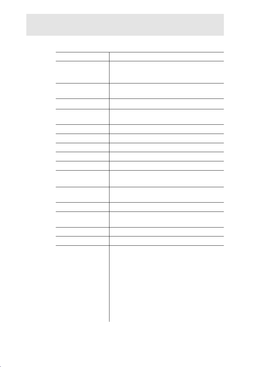
Pos: 35 /TD/Leistungsbeschreibung/Technische Dat en/testo 320/weitere Gerätedaten testo 320 @ 12\mod_13340 47465045_79.docx @ 115533 @ 3 @ 1
3.2.6. Other instrument data
Feature Values
Storage and
transport
temperature
Operating
temperature
Ambient humidity
Power supply
Protection class IP40
Weight 573 g
Dimensions 240 x 85 x 65 mm
Memory 500 measured values
Display Graphic colour display, 240 x 320 pixels
Gas leak testing
probe
Optimum rech. batt.
storage conditions
Battery charge time Approx. 5-6 h with mains unit supplied
Rechargeable
battery life
Data transfer IrDA, USB, Bluetooth® (option)
Bluetooth® (option) Range < 10 m
Warranty Measuring instrument: 24 months
-20 to 50°C
-5 to 45°C
0…90 % rH, not condensing
Rech. batt.: 3.7 V / 2.4 Ah
Mains unit: 5.0 V/1000 mA
visual indication (LED)
audible indication by buzzer
Charge level: capacity at 50-80% ambi ent
temperature: 10-20°C
Approx. 6 h (pump on, 20°C ambient
temperature)
O2 sensor: 24 months
CO sensor: 24 months
CO sensor with H2 comp.: 24 months
CO/H2 low sensor (TCHL): 24 mont hs
Flue gas probe: 24 months
Thermocouple: 12 months
Rech. batt.: 12 months
3 Specifications
15
Page 16
4 Product description
Pos
: 36 /TD/Überschriften/4. Produktbeschreibung @ 0\ mod_1173774846679_79.docx @ 310 @ 1 @ 1
4 Product description
Pos: 37 /TD/Produktbeschreibung/Übersicht/tes to 3xx/testo 320/testo 320 Beispiel Lieferumfang 0516 3 300 @ 15\mod_1386853316138_79.docx @ 180051 @ 233 @ 1
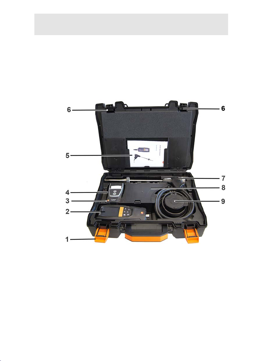
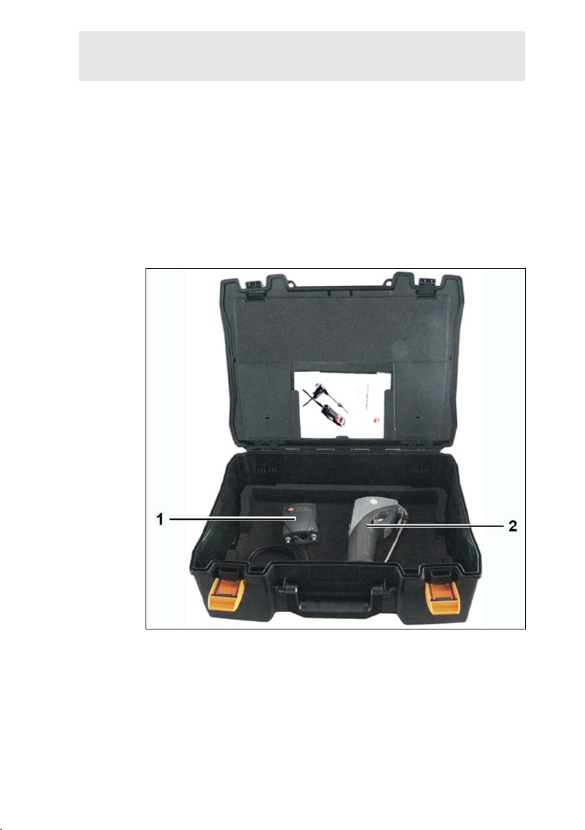
4.1. Case 0516 3300 (accessory)
Recommended for stowing away the measuring instrument and
accessories (example)
4.1.1. Bottom level view
16
1 Sealing clip
2 Flue gas analyser testo 320
3 Repository for printer accessories
• Spare batteries for IRDA printer
• 1 roll of spare thermal paper (0554 0568)
4 Repository for printer
• IRDA printer (0554 0549)
• • Bluetooth
®
/IRDA printer (0554 0620)
5. Instruction manual
Page 17
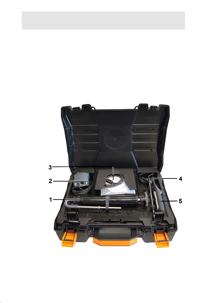
6 Lock testo 320
7 Probes
• Flue gas probe (e.g. 0600 9741)
• Pitot tube for heating check (0635 2050)
8 Large storage compartment
• Mains unit fortesto 320 (0554 1105)
• Differential temperature set (0554 1208)
• Spare dirt filter (0554 0040)
9 Round storage compartment
• Hose connection set with pressure adapter (0554 1203)
4.1.2. Top level view
4 Product description
1 Soot pump set (0554 0307)
2 Storage compartment
• Fine pressure probe (0638 0330)
17
Page 18
4 Product description
3 Storage compartment
• Capillary hose set for fine pressure probe (0554 121 5)
• Connecting cable for surface probe (0430 0143)
4 Combustion air temper ature probe (0600 9787)
Pos: 38 /TD/Produktbeschreibung/Übersicht/tes to 3xx/testo 320/testo 320 Beispiel Lieferumfang 0516 3 301 @ 15\mod_1386853065662_79.docx @ 180017 @ 2333 @ 1
5. Surface temperature probe Type K (0604 0994)
4.2. Case 0516 3301 (accessory)
Recommended for stowing away the measuring instrument and
accessories (example)
4.2.1. Bottom level view
1 Fine pressure probe (0638 0330)
2 testo 308 smoke tester ( 0632 0308)
18
Page 19
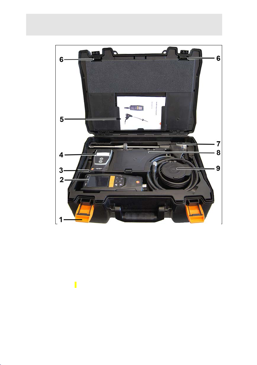
4.2.2. Middle level view
4 Product description
1 Sealing clip
2 testo 330-1 /-2 LL flue gas analyzer
3 Repository for printer accessories
• Spare batteries for IRDA printer
• 1 roll of spare thermal paper (0554 0568)
4 Repository for printer
• IRDA printer (0 554 0549)
• • Bluetooth®/IRDA printer (0554 0620)
5. Instruction manual
6 Lock
7 Probes
• Flue gas probe (e.g. 0600 9741)
• Pitot tube for heating check (0635 2050)
19
Page 20
4 Product description
8 Large storage compartment
• Mains unit for testo 330-1 /-2 LL (0554 1096)
• Differential temperature set (0554 1208)
• Spare dirt filter (0554 0040)
9 Round storage compartment
• Hose connection set with pressure adapter (0554 1203)
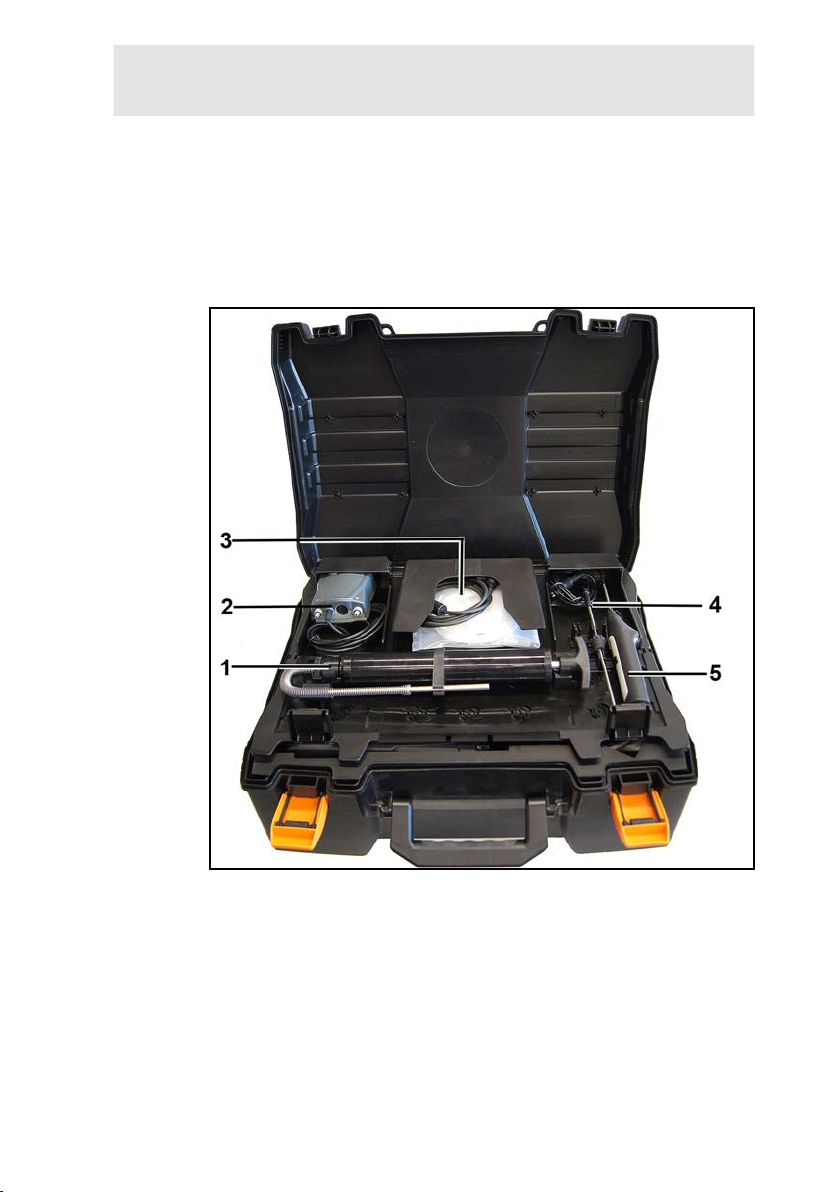
4.2.3. Top level view
1 Soot pump set (0554 0307)
2 Storage compartment
• Fine pressure probe (0638 0330)
3 Storage compartment
• Capillary hose set for fine pressure probe (0554 121 5)
• Connecting cable for surface probe (0430 1215)
4 Combustion air temper ature probe (0600 9787)
5. Surface temperature probe Type K (0604 0994)
20
Page 21
Pos: 39 /TD/Produktbeschreibung/Übersicht/tes to 3xx/testo 320/testo 320 Übersicht @ 11\mod_132739492 0497_79.docx @ 104294 @ 23 @ 1
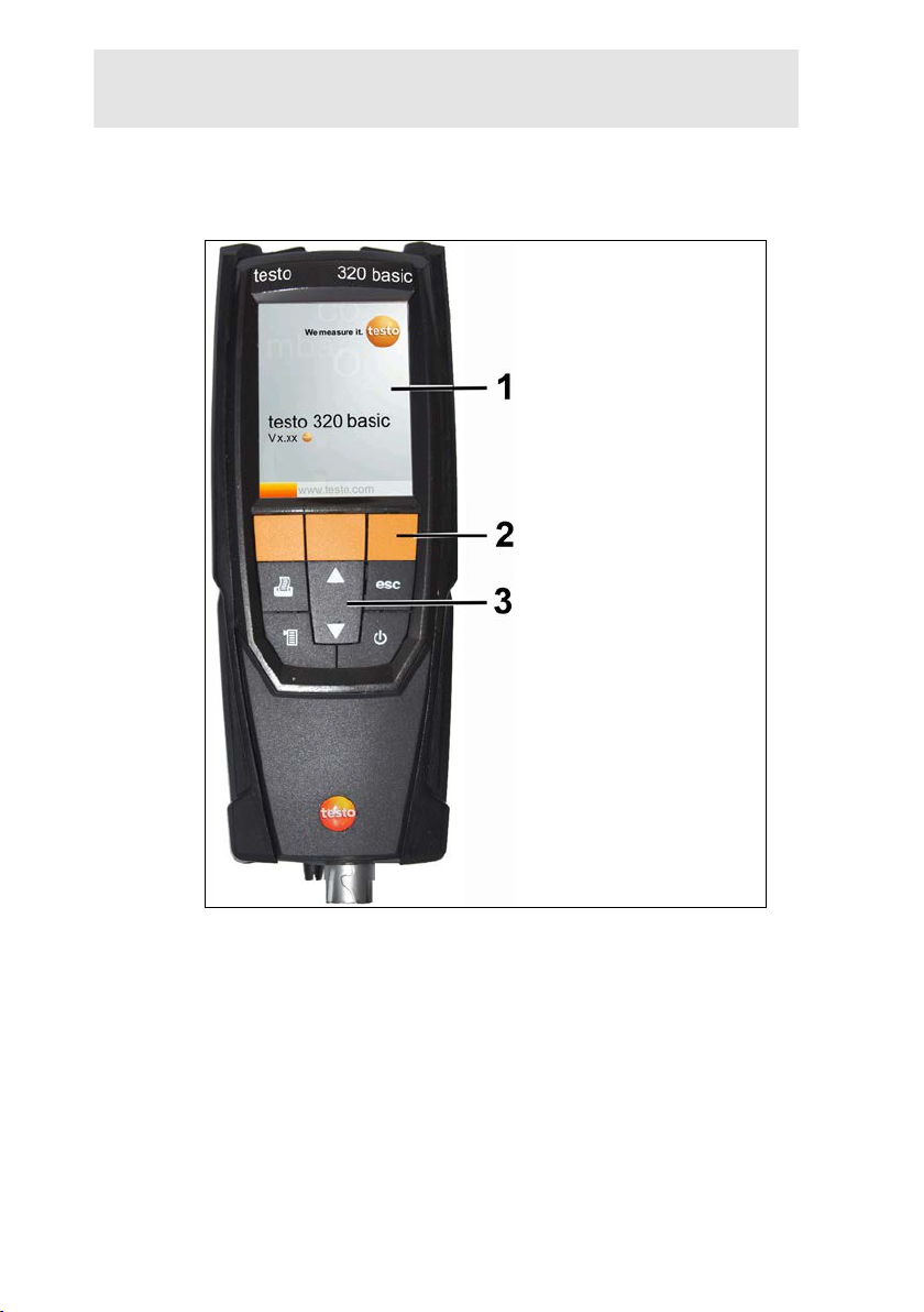
4.3. Measuring instrument
4.3.1. Front view
4 Product description
1 Display
2 Function keys
Pos: 40 /TD/Produktbeschreibung/Übersicht/tes to 3xx/testo 320/testo 320 Tastatur @ 11\mod_1327395389 844_79.docx @ 104327 @ 2 @ 1
21
3 Keypad
Page 22
4 Product description
4.3.2. Keypad
Button Functions
[ ]
[OK]
Example
[▲]
[▼]
[esc]
[ ]
[ ]
Pos: 41 /TD/Produktbeschreibung/Übersicht/tes to 3xx/testo 320/testo 320 Display @ 11\mod_132739545589 3_79.docx @ 104360 @ 2 @ 1
4.3.3. Display
Switch measuring instrument on / off
Function key (orange, 3x), relevant function is shown on
the display
Scroll up, increase value, navigate
Scroll down, reduce value, navigate
Back, cancel function
Open main menu
Transmit data to the Testo protocol printer.
22
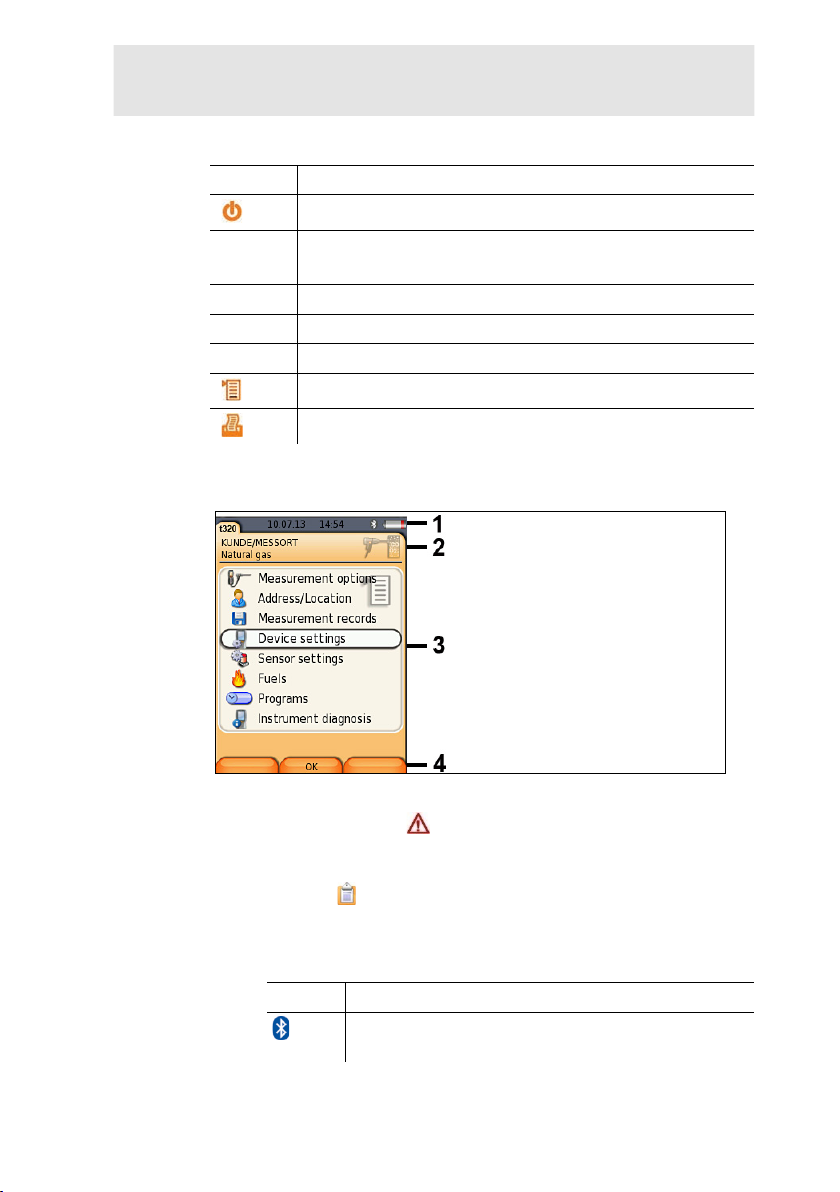
1 Status bar (dark grey back ground):
• Warning symbol (only if there is an instrument error,
display of error in instrument diagnosis menu), otherwise:
Instrument designation.
• Symbol (only if data is stored in the temporary memory).
• Display of date and time.
• Indication of Bluetooth
®
status, power supply and remaini ng
rechargeable battery capacity:
Icon Feature
blue symbol = Bluetooth
grey symbol = Bluetooth
®
®
on,
off
Page 23
I
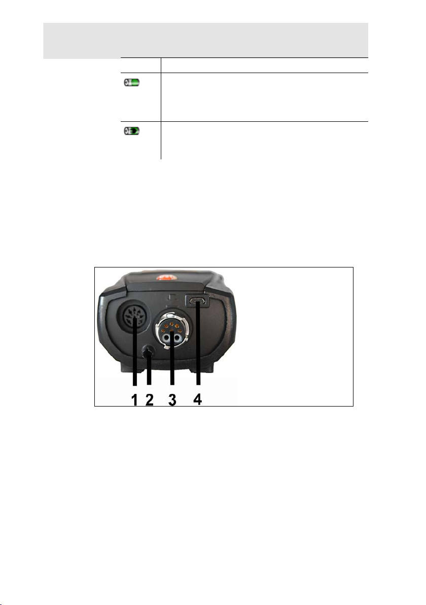
con Feature
Battery operation
Display of remaining rechargeable battery
capacity by colour and fill level of the battery icon
(green = 5-100%, red = < 5%)
Mains operation
Display of remaining rechargeable battery
capacity: see above
2 Info field of register t abs: Indication of selected
address/location, chosen fuel, chosen measurement type.
3 Selection field for functions (selected function appears against a
white background, unavailable functions are identified by grey
font) or display of measured values.
Pos: 42 /TD/Produktbeschreibung/Übersicht/t es to 3xx/testo 320/testo 320 Anschluesse @ 11\mod_132739554 0142_79.docx @ 104393 @ 3 @ 1
4 Function display for f unction keys.
4.3.4. Instrument connections
4 Product description
1 Probe socket
2 Gas outlet
3 Probe socket
4 Micro USB socket (battery charging, data transfer)
Test Equipment Depot - 800.517.8431 - 99 Washington Street Melrose, MA 02176
TestEquipmentDepot.com
23
Page 24
4 Product description
Pos: 43 /TD/Produktbeschreibung/Übersicht/tes to 3xx/testo 320/testo 320 Schnittstellen @ 11\mod_132 7395599329_79.docx @ 104426 @ 3 @ 1
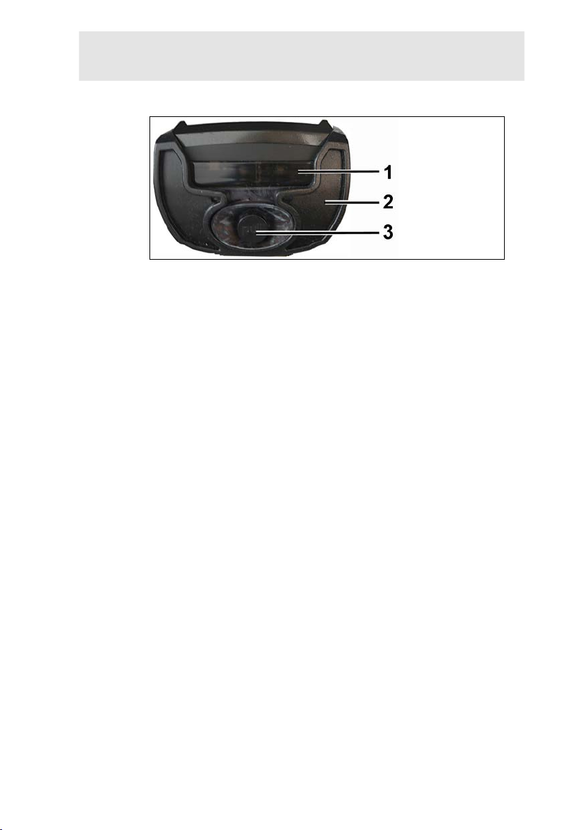
4.3.5. Condensate outlet and interfaces
1 Infrared interface (I r D A )
2 Bluetooth interface ( option)
3 Condensate outlet
24
Page 25
Pos: 44 /TD/Produktbeschreibung/Übersicht/tes to 3xx/testo 320/testo 320 Rückseite @ 12\mod_1337765959 098_79.docx @ 122422 @ 2 @ 1
4.3.6. Rear view
4 Product description
1 Attachment for carr ying strap
2 Condensate trap
3 Magnetic holder
25
Page 26
4 Product description
WARNING
Magnetic field
May be harmful to those with pacemakers.
> Keep a minimum distance of 15 cm between pacemaker and
instrument.
ATTENTION
Magnetic field
Damage to other devices!
> Keep a safe distance away from products which could be
damaged by the effects of magnetism (e. g. monitors,
computers or credit cards).
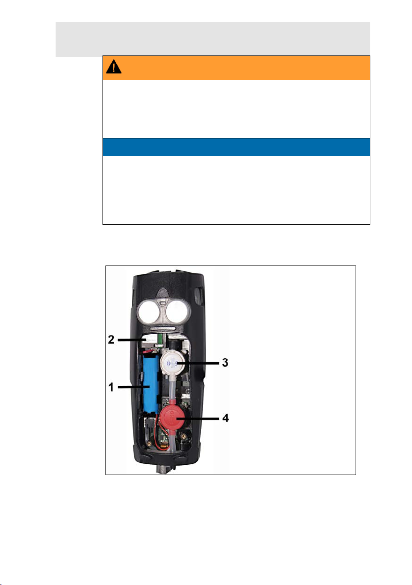
Pos: 45 /TD/Produktbeschreibung/Übersicht/tes to 3xx/testo 320/testo 320 Bauteile @ 11\mod_1327395702 136_79.docx @ 104459 @ 2 @ 1
4 Service lid
4.3.7. Components
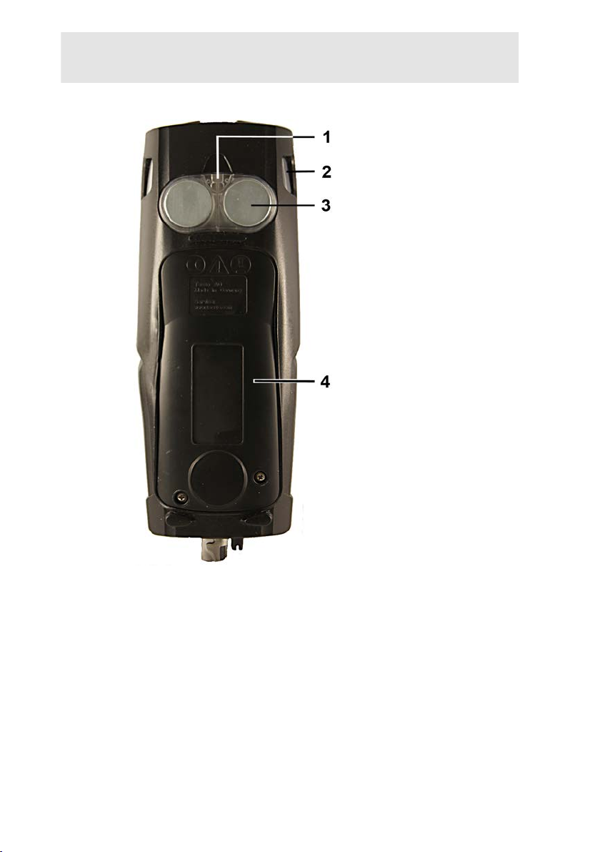
26
1 Rechargeable batter y
2 Measured gas pump
3 Slot for O2 sensor
4 Slot for CO sensor, COlow sensor or CO, H2-compensated
sensor
Page 27
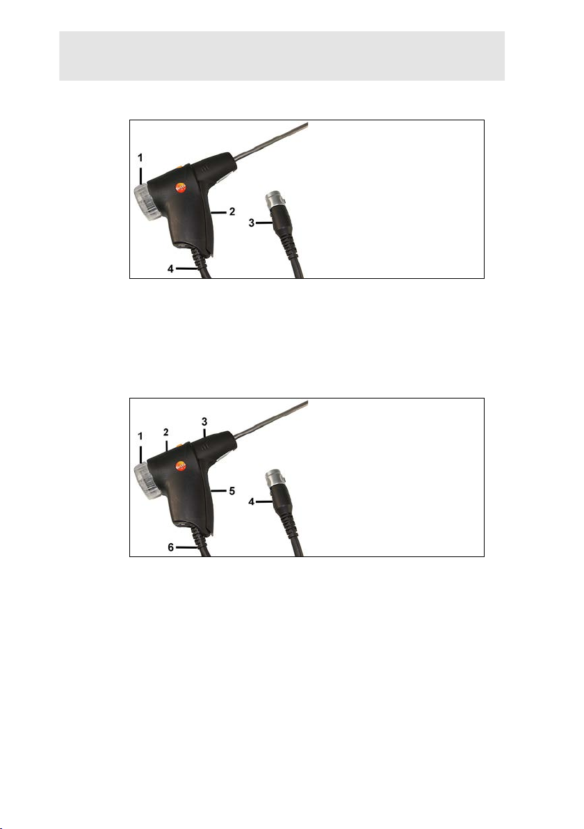
Pos: 46 /TD/Produktbeschreibung/Übersicht/tes to 3xx/testo 320/testo 320 Kompakte Abgassonde @ 12\mod_13 3777 7149320_79.docx @ 122456 @ 1 @ 1
4.4. Compact flue gas probe
1 Removable filter chamber with window and particle filter
2 Probe handle
3 Connector plug for meas ur i ng instrument
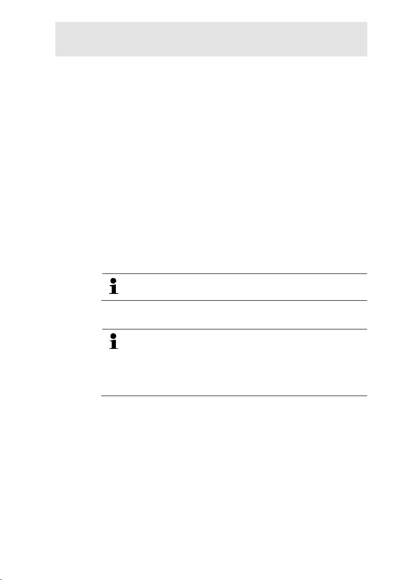
Pos: 47 /TD/Produktbeschreibung/Übersicht/t esto 3xx/testo 320/testo 320 Modulare abgassonde @ 11\mod_ 132 7395840242_79.docx @ 104525 @ 2 @ 1
4 Connecting cable
4.5. Modular flue gas probe
4 Product description
1 Removable filter chamber with window and particle filter
2 Lock release
3 Probe module
4 Connector plug for meas ur i ng instrument
5 Probe handle
6 Connecting cable
27
Page 28
5 First steps
Pos: 48 /TD/Überschriften/5. Erste Schritte @ 0\mod_117 377 4895039_79.docx @ 319 @ 1 @ 1
5 First steps
Pos: 49 /TD/Überschriften/5.1 Inbetriebnahme @ 0\mod_11 85342823812_79.docx @ 1885 @ 2 @ 1
5.1. Commissioning
Pos: 50 /TD/Erste Schritte/testo 320/Testo 320 Inbetri ebnahme @ 12\mod_1337087577642_79.docx @ 119173 @ @ 1
The measuring instrument is supplied with a rechargeable battery
already fitted.
> Charge the rechargeable battery fully before using the
Pos: 51 /TD/Überschriften/5.3 Produkt kennenlernen @ 0\ mod_1185342901015_79.docx @ 1894 @ 3 @ 1
5.2. Getting to know the product
Pos: 52 /TD/Erste Schritte/testo 320/testo 320 Produk t ke nnenlernen Netzteil_Akku @ 11\mod_1327396880793_7 9.docx @ 104592 @ 3 @ 1
measuring instrument, see Charging the battery, page 62.
5.2.1. Mains operation
If the mains unit is connected, the measuring instrument is
automatically powered from the unit.
1. Connect the mains unit instrument plug to the instrument's
micro USB socket.
Pos: 53 /TD/Erste Schritte/testo 320/testo 320 Sonden/ Füh ler anschließen @ 11\mod_1329914629852_79.docx @ 111183 @ 235 @ 1
2. Connect the mains plug of the mains unit to a mains socket.
During mains operation the battery is charged
automatically.
5.2.2. Connecting probes
Probe detection at the flue gas socket i s carried out
continuously. New probes are recogni s ed automatically.
Connect a probe to the probe socket befor e switching on
the measuring instrument or start s ensor detection
manually after changing the probe: [Options] → Sensor
detection.
28
Page 29
5 First steps
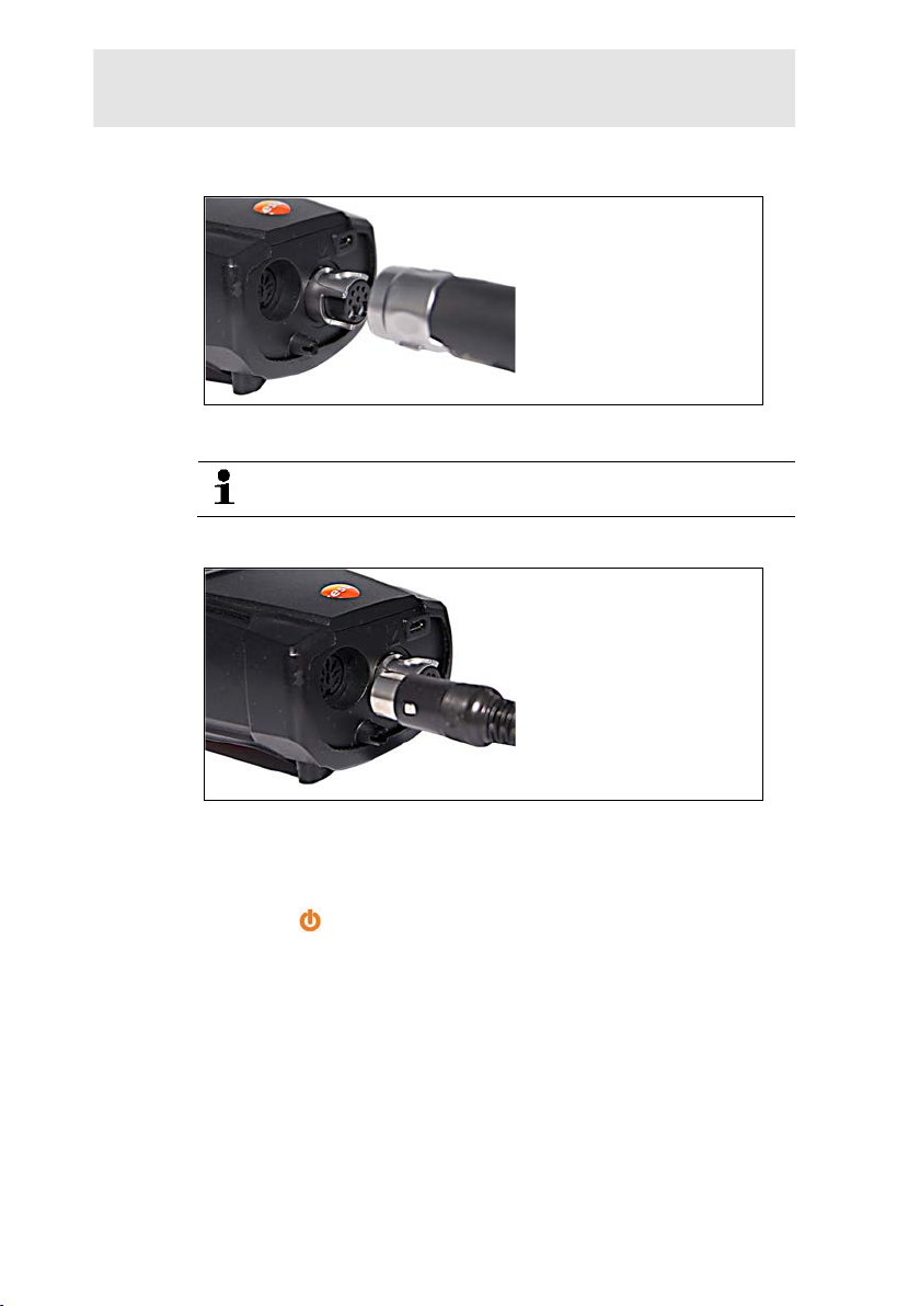
Connecting flue gas probes/gas pressu r e adapters/temperature adapters
> Insert the connector plug into the flue gas socket and lock by
slightly turning it clockwise (ba yo net lock).
There must be no more than one extension lead (0554
1201) between measuring instrument and flue gas probe.
Connecting other sensors
Pos: 54 /TD/Erste Schritte/testo 320/testo 320 Produk t ke nnenlernen Basisfunktionen @ 11\mod_132739842568 1_79. docx @ 104625 @ 353555555 @ 1
5.2.3. Switching on
> Press [ ].
- The s tart screen is displayed (duration: approx 15 s).
- During c ommissioning, when the instrument is switched on, the
Country version menu is displayed.
Set the country version:
1. Select the country version: [▲], [▼] → [OK].
2. Confirm confirmation request: Yes → [OK]
- The testo 320 switches off.
29
> Insert the connector plug of the probe int o the probe socket.
Page 30
5 First steps
3. Restart instrument: Press [ ].
- If t he voltage supply was interrupted for a longer period: The
Date/time menu opens.
- The gas sensors are zeroed.
- Ther e i s an i nstrument error: The Error diagnosis is displayed.
- The Measurement options menu is displayed.
5.2.4. Calling up the function
1. Select function: [▲], [▼].
- The s el ec ted function appears in a frame.
2. Confirm selection: [OK].
- The s el ec ted function is opened.
5.2.5. Entering values
Some functions require values ( num bers, units, characters) to be
entered. Depending on the selected function, the values are
entered either via a list field or an input editor.
List field
30
1. Select the value to be changed (numerical value, unit) : [▲],
[▼], [◄], [►] (depending on the selected function).
2. Press [Edit].
3. Set value: [▲], [▼], [◄], [►] (depending on the selected
function).
4. Confirm the entry: [OK].
5. Repeat steps 1 and 4 as required.
6. Save the entry: [Finished].
Page 31
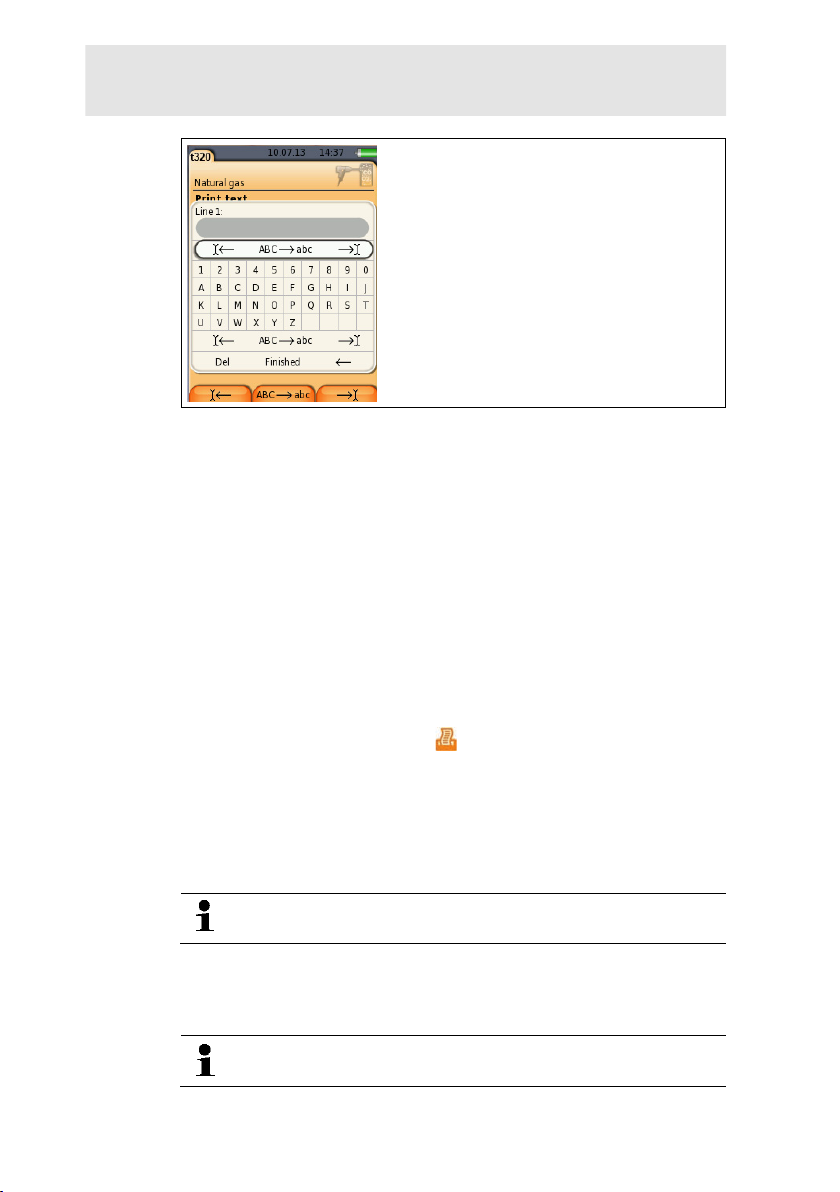
Input editor
5 First steps
1. Select the value (character) to be changed: [▲], [▼], [◄], [►].
2. Apply value: [OK].
Options:
> Toggle between upper/lower case:
select Ι← ABC→&$/ →Ι: [▲], [▼] → [ABC→&$/].
> Position the cursor in the text:
select Ι← ABC→&$/ →Ι: [▲], [▼] → [Ι←] or [→Ι].
> Delete character before or after the cursor:
select ← next → [▲], [▼] → [←] or [→].
3. Repeat steps 1 and 2 as required.
4. Save the entry: Select ← next → [▲], [▼]
5.2.6. Printing/saving data
Data is printed out via the key [ ]. Data is saved via the Options
menu. The Options menu is accessed via the left function k ey and
is available in many different menus.
To assign the right function key with the Save function or see
Assigning the right function key, page 36,
Only readings assigned a display field in the measurement view will
be saved / printed out.
The measurement data can be printed out parallel to the
saving process, while a measureme nt program is running.
To be able to transfer data to a record printer via infrared or
Bluetooth interface, the printer used must be enabled, see Fehler!
Verweisquelle konnte nicht gefunden werden., page Fehler!
Textmarke nicht definiert..
Graph charts can be printed out using t he Bluetooth® /
IRDA printer 0554 0620.
→ [Next].
31
Page 32
5 First steps
5.2.7. Saving data to the clipboard (temporary memory)
Using the clipboard, measurement r esults from various
measurement types can be combined to produce a common
record, which can then be printed out (see above). Data is saved to
the clipboard via the Options menu and the Clipboard command.
If there is data in the clipboard, t he s tatus bar shows the symbol .
If there is data in the clipboard and the Print command is triggered,
all data in the clipboard will be print ed out.
> [Options] → Delete clipboard: Any data saved to the
clipboard is deleted.
5.2.8. Confirming an error message
If an error occurs, an error message is s hown on the display.
> Confirming an error message: [OK].
Errors that have occurred but have n ot yet been rectified are
indicated by a warning symbol ( ) in the header.
Error messages that have not yet been c ancelled can be displayed
in the Error diagnosis menu, see Instrument diagnosis, page 35.
5.2.9. Switching off
Unsaved measured values are lost if the flue gas analyser
Pos: 55 /TD/Erste Schritte/testo 330/testo 330 Produk t ke nnenlernen Ordner_Messorte @ 6\mod_1278942335615_79. doc x @ 65332 @ 255553535 @ 1
is switched off.
> Press [ ].
- Depend i ng on the instrument status, the pump starts and the
sensors are rinsed until the switch-off thresholds (O
> 20 %,
2
other measurement parameters < 50 ppm) are reached. Rinsing
lasts no more than 3 minutes.
- The m easuring instrument switches off.
5.3. Address/Location
All measuring values can be saved under the currently active
location. Measuring values that have not been saved are lost when
the measuring instrument is switched off!
Addresses and locations can be cr eated, edited, copied and
enabled. Addresses and locations (incl. protocols) can be deleted.
Call up function:
> [ ] → Address/Location → [OK].
There are various options for opening address.
1. Edit search setting: [Edit].
32
Page 33
5 First steps
2. Select search setting: [▲], [▼] → [OK].
Possible settings:
• Show all: All address/location are displayed.
• Search: A search text only brings up address/locati on that
contain characteristics of the searc h text.
• Filter: Individual letters or numbers can be selected. All data
beginning with the relevant letter/number is displayed.
The initial letter is the determining factor for the filter
function, and this can only be select ed individually. The
search function can also be used to f ind a series of several
letters within the address!
3. Carry out search according to search setting: [Search]
Show all
1. Select address: [▲], [▼].
2. Show details: [Details].
3. Enable a location: select the location → [OK].
- The location is activated.
> Open measurements menu: press [OK] again.
Search
1. Edit search criteria: [►] → [Edit].
2. Select search criteria: [▲], [▼] → [OK].
Possible options:
• Contact person
• Address
• Town/city
• Postcode
• Street
- The s el ec ted criterion is displayed.
3. Call up entry field for search text: [►] or [▼]
> Enter search text → [Finished]
Do not use the special character * as a placeholder.
33
Page 34

5 First steps
Filter
1. Edit search criteria: [Edit].
2. Select search criteria: [▲], [▼] → [OK].
Possible options:
• Contact person
• Address
• Town/city
• Postcode
• Street
- The s el ec ted criterion is displayed.
3. Enable tab: [▼]
4. Select the required tab: [▲], [▼] and sometimes [◄], [►]→
[Filter].
- The s earch result for the relevant letter or number is displayed.
Create a new measuring location:
A location is always created under an address.
1. Select the address in which the location is to be created.
2. [Options] → New/Location → [OK].
3. Enter values or make settings.
4. Finalise the entry: [Finished].
34
Other location options:
> [Options] → Edit location: make changes to an existing
location.
> [Options] → Copy location: make a copy of an existing
location in the same address.
> [Options] → Delete location: delete an existing location. Create new address:
1. [Options] → New address → [OK].
2. Enter values or make settings.
3. Finalise the entry: [Finished].
Other address options:
• Edit address: make changes to an existing folder.
• Copy address: make a copy of an existing folder.
• Delete address: delete an existing folder, including the
locations created therein.
• Delete All addr esses: delete all existing folders, including the
locations created in them.
Page 35

Pos: 56 /TD/Erste Schritte/testo 320/testo 320 Produk t kennenlernen Protokolle @ 11\mod_1327399737788_79. docx @ 104658 @ 1355 @ 1
5.4. Measurement records
Call up function:
> [ ] → Measurement records → [OK].
There are various options for opening records. see
Address/Location, page 32.
Displaying a record:
1. Choose the required record from the detailed view.
2. Print [Data].
Printing all records for a location:
1. Select measuring location: [▲], [▼]
2. Start printout: [ ].
- All records for the location are printed out.
Options:
> [Options] → Delete Record: delete the selected record.
> [Options] → Delete all Records: delete all saved rec ords for a
Pos: 57 /TD/Erste Schritte/testo 320/testo 320 Produk t ke nnenlernen Gerätediagnose @ 11\mod_1327400657624_79. docx @ 104724 @ 3555 @ 1
location.
5.5. Instrument diagnosis
Important operating values and instrument data are displayed. The
status of the sensors and any instrument er rors not yet rectified can
be displayed.
Call up function:
> [ ] → Instrument diagnosis → [OK].
Displaying instrument errors:
> Error diagnosis→ [OK].
- Unrectified errors are displayed.
> Display next/previous error: [▲], [▼].
Displaying sensor diagnosis:
1. Sensor diagnosis → [OK].
2. Select sensor. [▲], [▼].
- The s tatus of the sensor is indicated by a traffic l ight.
A sensor is able to recover. The sensor status indication
may therefore change from yellow to green or from red to
yellow.
5 First steps
Displaying instrument information
> Device information → [OK].
- Information is displayed.
35
Page 36
6 Using the product
Pos: 58 /TD/Überschriften/6. Produkt verwenden @ 0\mod_ 1173 774928554_79.docx @ 328 @ 3 @ 1
6 Using the product
Pos: 59 /TD/Überschriften/6.1 Einstellungen vorn ehmen @ 0\mod_1184584321421_79.docx @ 1863 @ 3 @ 1
6.1. Performing settings
Pos: 60 /TD/Produkt verwenden/testo 330/testo 330 Rec hte Funktionstaste belegen @ 6\mod_1279283093786_79.doc x @ 67168 @ 3 @ 1
6.1.1. Assigning the right function key
The right function key can have a functi on from the Options menu
assigned to it. The menu Options is accessed via the left function
key and is available in many different menus. This assignment is
only valid for the currently opened menu / the opened function.
✓ A menu / function is opened in which the Options menu is
Pos: 61 /TD/Produkt verwenden/testo 350 neu/testo 350 Ger ät eeinstellungen CU/testo 350 Geräteeinstellunge n_Ueberschrift @ 5\mod_1266322627982_79.doc x @ 58663 @ 3 @ 1
6.1.2. Instrument settings
Pos: 62 /TD/Produkt verwenden/testo 330/testo 330 Gerä teeinstellungen aufrufen @ 6\mod_1279008333499_79. doc x @ 65426 @ @ 1
Pos: 63 /TD/Produkt verwenden/testo 320/testo 320 Mess wertanzeige @ 11\mod_1327406858634_79.docx @ 104758 @ 4555 @ 1
displayed on the left function key.
1. Press [Options] .
2. Select option: [▲], [▼].
Depending on the menu / function from which the Options menu
was opened, the following functions are available.
3. Assign the selected function to the right function key: Press
[Config. Key].
It is assumed that the contents of the chapter First steps
(see First steps, page 28) are known.
Calling up a function:
> [ ] → Device Settings.
see First steps, page 28
6.1.2.1. Measurement view
The parameters/units and the display (number of measured values
shown per display page) can be set.
The settings are only valid for the currently chosen measurement
type, which is indicated by the symbol i n the info field.
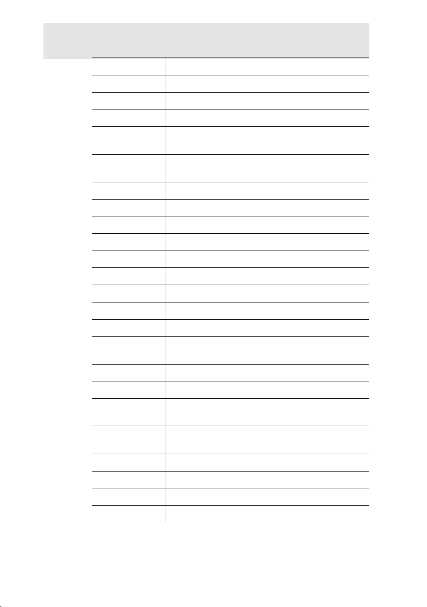
Total overview of selectable meas urement parameters and units
(available selection depends on the set country version and
selected measurement type):
Display Measurement param eter
FT
AT
36
Flue gas temperature
Combustion air temperature
Page 37
Display Measurement param eter
GT
O2
CO2
qA+
Instrument temperature
Oxygen
Carbon dioxide
Flue gas loss with due consideration of the
calorific value range
η+
Efficiency with due considerati on of the calorific
value range
CO
COunv
λ
COumg
CO2um
O2ref
Draught
ΔP
E draught
E-ΔP
Carbon monoxide
Carbon monoxide undiluted
Air ratio
Ambient carbon monoxide
Ambient carbon dioxide
Oxygen reference
Draught measurement
Differential pressure measurement
External draught (external micr o pressure probe)
External differential pressure (external micro
pressure probe)
cCO
ExAir
qA
Carbon dioxide reduction
Air surplus
Flue gas loss without due considerat ion of the
calorific value range
η
Efficiency without consideration of the heat value
range
Dew Pt
Nett
GI
ET
Flue gas dew point temperature
Differential temperature
Toxin index
qA+ - qA
6 Using the product
37
Page 38

6 Using the product
Calling up the function:
> [ ] → Device settings → [OK] → Measurement view →
[OK]
Changing the parameter/unit in a line:
1. Select the line: [▲], [▼] → [Edit]
2. Select the parameter: [▲], [▼] → [OK]
3. Select the unit: [▲], [▼] → [OK]
4. Save changes: [OK]
Options:
> [Options] → Number of lines: change the number of
measured values per display page.
> [Options] → Blank line: insert a blank line in front of the
selected line.
> [Options] → Delete line: delete the selected line.
> [Options] → Factory setting: reset the measured value
Pos: 64 /TD/Produkt verwenden/testo 330/testo 330 Alarsc hwellen @ 6\mod_1279021018511_79.docx @ 65490 @ 45 @ 1
display to the factory settings.
6.1.2.2. Alarm limits
Alarm limits can be set for several display parameters. An audible
alarm signal is triggered when the alarm l imit is reached.
Calling up the function:
> [ ] → Instrument Settings → [OK] → Alarm Limits → [OK]
Switching alarm signals on / off, changing alarm limits:
1. Select function or parameter: [▲], [▼] → [Edit].
2. Set parameter: [▲], [▼] and partly [◄], [►] → [OK].
3. Save changes: [Finished].
Pos: 65 /TD/Produkt verwenden/testo 320/testo 320 Ei nhei ten @ 11\mod_1327407419025_79.docx @ 104791 @ 45 @ 1
> Reset the enabled value to the factory setting: [Standard].
6.1.2.3. Units
The units used for parameters in configuration menus can be set.
Call up function:
> [ ] → Device settings → [OK] → Units → [OK].
38
Page 39

6 Using the product
Adjustable units
Parameter Unit
Altitude m, ft
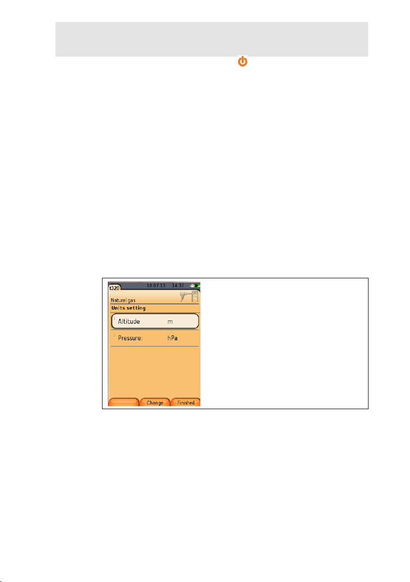
Pressure mbar, hPa
1. Select the line: [▲], [▼]→ [Edit].
2. Select the unit to be changed: [▲], [▼] → [OK].
Pos: 66 /TD/Produkt verwenden/testo 330/testo 330 Datu m _ Uhrzeit @ 6\mod_1279023342203_79.docx @ 65553 @ 45 @ 1
3. Confirm the entry: [Finished].
6.1.2.4. Date / time
Date, time mode and time can be set.
Calling up the function:
> [ ] → Instrument Settings → [OK] → Date/Time → [OK]
Setting date/time:
1. Select parameter: [◄], [▲], [▼] → [Edit].
2. Set parameter: [▲], [▼] and partly [◄], [►] → [OK].
Pos: 67 /TD/Produkt verwenden/testo 330/Testo 330 Energi e verwaltung @ 6\mod_1279023810346_79.docx @ 65585 @ 45 @ 1
3. Save changes: [Save].
6.1.2.5. Energy management
Automatic instrument shutdo wn (Auto-Off) and switching off of the
display light in battery operation can be set.
Calling up the function:
> [ ] → Instrument Settings → [OK] → Energy Management
→ [OK]
Making settings:
1. Select function or parameter: [▲], [▼] → [Edit].
2. Set parameter: [▲], [▼] and partly [◄], [►] → [OK].
Pos: 68 /TD/Produkt verwenden/testo 330/testo 330 Di splay @ 6\mod_1279025603358_79.docx @ 65617 @ 4 @ 1
3. Save changes: [Finished].
6.1.2.6. Display brightness
The intensity of the display illumination can be set.
Calling up the function:
> [ ] → Instrument Settings → [OK] → Display Brightness →
[OK]
Performing settings
> Set parameter: [◄], [►] → [OK].
39
Page 40
6 Using the product
Pos: 69 /TD/Produkt verwenden/testo 330/testo 330 Aus wahl_Messart @ 15\mod_1386331304928_79.docx @ 179731 @ 45 @ 1
6.1.2.1. Choose measurement type
Individual measurement types can be shown or hidden. These are
displayed or hidden accordingly un der Measurement options.
Call up function:
> [ ] → Device settings → [OK] → Choose measurement
type → [OK].
Show or hide measurement types :
1. Select measurement type: [▲], [▼]
2. Enable / disable measurement type: [ ] (enabled), [ ]
(disabled)
Pos: 70 /TD/Produkt verwenden/testo 330/Testo 330 Druc ker @ 6\mod_1279025854485_79.docx @ 65649 @ 455 @ 1
3. Save selection: [Finished].
6.1.2.2. Printer
The headers (lines 1-3) and the footers f or the printout can be set.
The printer that is used can be activat ed.
Calling up the function:
> [ ] → Instrument Settings → [OK] → Printer → [OK]
Activating the printer:
The printer 0554 0543 can only be selected after the
Bluetooth
Bluetooth
1. Select Printer → [OK].
2. Select the printer: [▲], [▼] → [OK].
- The pr i nter is activated and the menu Printer is opene d.
®
-interface has been activated, see
®
, page 41.
Pos: 71 /TD/Produkt verwenden/testo 330/testo 330 Blu et ooth @ 6\mod_1279026530745_79.docx @ 65681 @ 45 @ 1
40
Configuring the print text:
1. Print text → [OK].
2. Select function: [▲], [▼] → [Edit].
> Enter values for Line 1, Line 2, Line 3 and the Footnote
> Print out system data and/or customer data: [ ]
3. Save the entry: select [Finished].
see Bluetooth
®
, page 41
Page 41

6.1.2.3. Bluetooth®
This menu is only available if the inst r ument is equipped with
Bluetooth. The Bluetooth module can be switched on / off.The relay
can now be tested.
Calling up the function:
> [ ] → Instrument Settings → [OK] → Bluetooth → [Edit].
Making settings:
Pos: 72 /TD/Produkt verwenden/testo 330/testo 330 Spr ac he @ 6\mod_1279026896670_79.docx @ 65713 @ 45 @ 1
> Set parameter → [OK].
6.1.2.4. Language
The menu language can be set. The number of available
languages depends on the activated country version, see Country
version, page 41.
Calling up the function:
> [ ] → Instrument Settings → [OK] → Language → [OK]
Activating the language:
> Select the language → [OK].
Pos: 73 /TD/Produkt verwenden/testo 330/testo 330 Land es version @ 6\mod_1279026924467_79.docx @ 65745 @ 35 @ 1
see Country version, page 41
6 Using the product
6.1.2.5. Country version
Changing the country version ma y alter the basis for calculation
and therefore also the displayed meas ure ment parameters, fuels,
fuel parameters and calculation formulas.
The selection of the country version influences the menu languages
that can be enabled.
Calling up the function:
> [ ] → Instrument Settings → [OK] → Country Version →
[OK]
This action can be password protect ed. A password is
specified in the menu Password Protection, see
Password protection, page 42.
Possibly:
> Enter the password: [Enter] → Enter password → [Next] →
[OK].
41
Page 42

6 Using the product
Setting the country version:
1. Select the country version: [▲], [▼] → [OK].
2. Confirm the confirmation request: Yes → [OK]
- The s ystem is restarted.
Pos: 74 /TD/Produkt verwenden/testo 330/testo 330 Pass wortschutz @ 6\mod_1279028157194_79.docx @ 65809 @ 45 @ 1
see Password protection, page 42
6.1.2.6. Password protection
The password protection is only vali d for functions identified by the
following symbol: or .
Password protection can be activated / deactivated, the password
can be changed.
To deactivate the password protec tion change the password to
Pos: 75 /TD/Produkt verwenden/testo 320/testo 320 Sens oreinstellungen_Überschrift @ 11\mod_132740792322 8_79.docx @ 104824 @ 4 @ 1
0000 (factory setting).
Calling up the function:
> [ ] → Instrument Settings → [OK] → Password Protection
→ [OK]
Possibly:
> Enter the currently valid password:
[Enter] → Enter password → [Next] → [OK].
Changing the password:
1. [Edit].
2. Enter the new password → [Next].
3. [Edit].
4. Enter the new password again to confirm → [Next].
5. Save changes: [Finished].
6.1.3. Sensor settings
Pos: 76 /TD/Produkt verwenden/testo 320/testo 320 O2_ Referenz @ 11\mod_1327408118653_79.docx @ 104890 @ 35 @ 1
6.1.3.1. O2 reference
The O2 reference value can be set.
The O2 reference value setting may be password protected, see
Password protection, page 42.
Call up function:
> [ ] → Sensor settings → O2 reference → [Edit].
Possibly:
> Enter the password: [Enter] → Enter password → [Next] →
[OK].
Setting the O
> Set value → [OK].
42
reference:
2
Page 43
Pos: 77 /TD/Produkt verwenden/testo 320/testo 320 Sens orschutz @ 11\mod_1327408172169_79.docx @ 104923 @ 35 @ 1
WARNING
6.1.3.2. Sensor protection
Protection limits can be set to protect the sensors against overload.
Sensor protection switch-off is available for the CO sensor.
Sensor protection is activated if the threshold is exceeded.
To disable sensor protection, the threshold values must be set to 0
ppm.
Call up function:
> [ ] → Sensor settings → Sensor protection → [OK].
Setting sensor protection thresholds:
1. Select parameter: [Edit].
2. Set value → [OK].
Pos: 78 /TD/Produkt verwenden/testo 320/testo 320 J ustage @ 11\mod_1327408238998_79.docx @ 104956 @ 25 @ 1
3. Save changes: [Finished].
6.1.3.3. Recalibration/adjustment
The CO sensor can be recalibrated and adjusted.
For recalibration/adjustment, Testo recommends using calibration
adapter 0554 1205 or sending the ins trument off to Testo Customer
Service.
If obviously unrealistic measur ed v alues are displayed, the
sensors should be checked (calibrat ed) and, if required,
adjusted.
Adjustments made with low gas concentrations can lead to
accuracy deviations in the upper meas uring ranges.
Call up function:
> [ ] → Sensor settings → Recalibration → [OK].
Possibly:
> Enter the password: [Enter] → Enter password → [Next] →
[OK].
- Gas zeroing (30 s).
6 Using the product
Performing recalibration/adjustment:
Dangerous gases
Danger of poisoning!
> Observe safety regulations/ accident prevention regulations
when handling test gas.
> Use test gases in well ventilated room s only.
43
Page 44
6 Using the product
1. Connect the calibration adapter to the flue gas socket .
2. Enable CO measurement parameter: [OK].
3. [Edit] → Enter the test gas concentration (nominal value).
4. Attach the connecting line of the test gas bottle to t he
calibration adapter.
5. Apply test gas to the sensor.
6. Start recalibration: [Start].
7. Apply the target value once the actual value is st abl e
(adjustment): [OK].
-orCancel (no adjustment): [esc].
Pos: 79 /TD/Produkt verwenden/testo 320/testo 320 Br enns toffe @ 12\mod_1337858675263_79.docx @ 124408 @ 3555 @ 1
8. Save changes: [Finished].
6.1.4. Fuels
The fuel can be selected. The fuel-specific coefficients and limits
can be set.
Call up function:
> [ ] → Fuels → [OK].
In order to maintain the measuring acc ur acy of the
instrument, the correct fuel must be sel ec ted or configured.
Correct representation of measuring results is only assured
if the threshold values for the ideal r ange of the
corresponding measurement task have been set correctly.
The pre-set threshold values are typical values for the
selected system type and the chosen t yp e of fuel.
44
Activating fuels:
> Select the fuel → [OK].
- The fuel is activated and the main menu is opened.
Setting coefficients:
1. Select the fuel → [Coeff.].
2. Select the coefficients: [Edit].
Possibly:
> Enter the password: [Enter] → Enter password → [Next] →
[OK].
3. Set values → [OK].
4. Save changes: [Finished].
Page 45
Setting limits:
1. Select limit → [Edit].
2. Set values → [OK].
Pos: 80 /TD/Überschriften/6.3 Messungen durchführ en @ 0\mod _118 4584650078_79.docx @ 1872 @ 2 @ 1
6.2. Measuring
Pos: 81 /TD/Produkt verwenden/testo 320/testo 320 Messu ng vorbereiten @ 11\mod_1327409352859_79.docx @ 104989 @ 35555 455444 @ 1
3. Save changes: [Finished].
6.2.1. Preparing for measurement
The First steps chapter (see First steps, page 28) must
have been read.
6.2.1.1. Testing for leaks
The entire measurement system (pr obe, condensate trap, hoses
and connections) must be tested for leak s before each
measurement to avoid incorrect m eas urements due to the
infiltration of external air. Testing is carried out while the pump is
running and may be performed by attac hi ng a compress ed ball oo n
pump. The measurement system is leak -tight if the balloon pump is
not filled with air.
6.2.1.2. Zeroing phases
Measuring the combustion air temp erature
If no combustion air temperature probe is connected, during the
zeroing phase, the measured temper ature of the flue gas probe is
taken as the combustion air temperature.
The flue gas probe should not be in the flue gas duct during
the zeroing phase.
All dependent parameters are calculated using this value. This
method of measuring combustion air temperature is sufficient for
systems dependent on ambient air.
If a temperature probe is connected, the combustion air
temperature is measured continuously via this probe.
6 Using the product
Gas zeroing
When the instrument is switched on, the measurement menu is
opened and the gas sensors are zeroed.
The flue gas probe must be in fresh air dur ing the zeroing
phase!
45
Page 46
6 Using the product
Draught/pressure zeroing
The pressure sensors are zeroed when a pressure measuring
function is called up.
The flue gas probe must be in the fresh air during the
zeroing phase / the instrument must not be pressurised
during zeroing.
6.2.1.3. Using flue gas probe
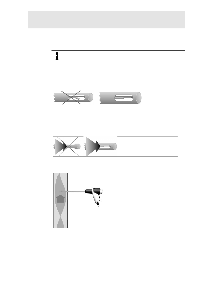
Checking the thermocouple
The thermocouple of the flue gas probe must not lie against the
probe cage.
> Check before use. Bend the thermocouple back if necessary.
Aligning the flue gas probe
The flue gas must be able to flow freely pas t the thermocouple.
> Align the probe by turning it as required.
The tip of the probe must be in the centre of the flue gas flow.
> Align the flue gas probe in the flue gas duc t so that the tip is in
the core current (area of the highest f l ue gas temperature).
46
Page 47
6.2.1.4. Measurement view
Only those measurement parameters and -units that are enabled in
the reading display appear in the reading display, in the saved
measurement records and on record pr i ntouts.
> Before carrying out measurements, s et up the measured value
display in such a way that the required parameters and units
are enabled, see Measurement view, page 36.
6.2.1.5. Setting the location and fuel
Before carrying out measurements, the location and fuel must be
correctly selected, see Address/Location, page 32
and
Pos: 82 /TD/Produkt verwenden/testo 320/testo 320 Abga smessung @ 11\mod_1327409708812_79.docx @ 105022 @ 35555 @ 1
6.2.2. Flue gas
see Fuels, page 44.
To achieve usable measurement results , the measurement
period of a flue gas measurement should be approx. 3 min
and the measuring instrument should di splay stable
measuring values.
Call up function:
1. [ ] → Measurement options → [OK] → Flue Gas → [OK].
2. Select the fuel → [OK].
6 Using the product
Carrying out the measurement:
1. Start measurement: [ ].
If a separate measurement of CO undiluted has not yet
been carried out, this value is calculated using the
measured values of the flue gas probe and is updated
continuously.
If CO undiluted and/or a draught measur ement has already
been carried out separately, the value obtained is applied.
- The measured values are displayed.
2. End measurement: [ ].
Options
> [Options] → Clipboard: data is saved to the clipboard.
> [Options] → Delete clipboard: any data saved to the c l ipboard
is deleted.
> [Options] → Save: the me asured values are saved in a record.
> [Options] → Fluegas matrix: the measured valu es are
displayed as a flue gas matrix, see below.
47
Page 48

6 Using the product
> [Options] → Number of lines: change the number of
> [Options] → Recalibrate: the gas sensors are set to zero.
> [Options] → Measurement view: (This function is not available
Showing the flue gas matrix
This function is only available if t he measurement parameter CO
has been activated in the measured value display.
Call up function:
✓ The flue gas function is open.
> [Options] → Fluegas matrix.
Options
> [Options] → Clipboard: data is saved to the clipboard.
> [Options] → Delete clipboard: any data saved to the c l ipboard
> [Options] → Save: the me asured values are saved in a record.
> [Options] → Show numeric value: data is displayed as
> [Options] → System type: (This function is not available
> [Options] → Reset graphic: the displayed graphi c al v alues are
> [Options] → Thresholds: (This function is not available during
> [Options] → CO + O2 or CO + CO2: choose which paramet er
> [Options] → Measurement view: (This function is not available
Pos: 83 /TD/Produkt verwenden/testo 320/testo 320_ Zu gm ess ung @ 11\mod_1327410556665_79.docx @ 105055 @ 355 @ 1
3.
measured values per display page.
during a measurement): the measured value display menu is
opened.
is deleted.
numerical values.
during a measurement) Set the system type to be able to
configure the ideal zone (green) of the flue gas matrix, using the
limits pre-configured for each system type.
deleted.
a measurement) Enter limits to be able to c onfigure the ideal
zone (green) of the flue gas matrix.
should be assigned to the x-axis of the display matrix (O2 or
CO2).
during a measurement) Open the measured value display
menu.
48
Page 49
6.2.3. Draught measurement
Call up function:
✓ A flue gas probe m ust be connected.
1. [ ] → Measurement options → [OK] → Draught → [OK].
Carrying out the measurement:
During the zeroing phase, the flue gas probe must be
outside the flue gas duct.
Do not measure for longer than 5 min, as a drift of the
pressure sensor means that the measured values may be
outside the tolerance limits.
1. Start measurement: [ ].
- Draught zeroing is carried out.
2. Position the flue gas probe in the hot spot (area of the highest
flue gas temperature).
The display showing the maximum measured flue gas
temperature (AT max ) helps when positioning the probe.
- The m easured value is displayed.
3. End measurement [ ].
Options:
> [Options] → Clipboard: Data is saved to the clipboard.
> [Options] → Delete clipboard: Any data saved to the clipboard
is deleted.
> [Options] → Save: The measured values are saved in a
record.
> [Options] → Measurement view: (This function is not available
during a measurement): The measured v alue display menu is
Pos: 84 /TD/Produkt verwenden/testo 320/testo 320_Fein stdrucksonde (Landesversion DE) @ 13\mod_13421660386 08_79.docx @ 137097 @ 3 @ 1
4.
6.2.4. External micro pressure probe
opened.
The following measurements can be per formed using the external
micro pressure probe (0638 0330):
• Ext-Draught
• Ext-Delta-P Single meas.
• Ext-Delta Pro gram
• Ext 4Pa-Measurement ( only available if Germany country
version is selected)
• Heating Check (only available if Germany country vers ion is
selected)
See instruction manual for externa l micro pressure probe.
6 Using the product
49
Page 50

6 Using the product
Pos: 85 /TD/Produkt verwenden/testo 320/testo 320_ Mit telwert (Landesversion IT) @ 13\mod_1342177433764_79. docx @ 137329 @ 355 @ 1
5.
6.2.5. Average
This function is only available when the Italy country version is
selected.
Call up function:
✓ A flue gas probe or a multi-hole probe (0554 5762) is
connected.
> [ ] → Measurement options → [OK] → Average → [OK].
Options:
> [Options] → Recalibrate: the gas sensors are set t o z ero.
> [Options] → Addresse/Location: the Addres s /Location folder
is opened.
> [Options] → Fuels: select fuel.
> [Options] → Sensor detection: once the probe has been
changed, start sensor detection manually.
To calculate the average, a series of 3 measurements are carried
out.
Averaging:
1. Position the flue gas probe in the centre of flow (area of t he
highest flue gas temperature).
2. Start measurements
> First measurement: [ ].
> Second and third measurement: [OK]
- The s et measurement parameters, measurement period and
measured values are displayed.
- A signa l i s sounded after 2 min (recommended measurement
period)
3. End measurements: [ ].
- Once the series of measurements has been carried out, the
record for averaging is displayed.
> If necessary, scroll through the rec or d: [◄], [►]
4. [Next]
5. Enter checks:
> Select criterion: [▲], [▼].
> Change value: [Edit] → [▲], [▼] → [OK].
6. End check: [Close]
- The r ecord is saved.
50
Page 51
Pos: 86 /TD/Produkt verwenden/testo 320/testo 320_BI MSCHV @ 11\mod_1327410706836_79.docx @ 105088 @ 355 @ 1
7.
6.2.6. BImSchV
This function is only available when the Germany country version
is selected.
A qA average value measurement can be carried out. For this
purpose the average is determined cont i nuously over a period of 30
s, the measuring cycle takes 1 s. The average values actually valid
at the corresponding time of recordi ng are displayed.
Call up function:
✓ A flue gas probe and a combustion air temperature probe must
be connected.
> [ ] → Measurement options → [OK] → BImSchV → [OK].
> Select the fuel → [OK].
Carrying out the measurement:
1. Start the measurement series: [ ]
Wait for the balancing time, until O
20%.
2. [Next].
- The qA measured values (O
- The m easurement stops automatically.
- The m easured values are displayed and saved automatically in
a record.
3. End measurement: [Close]
or
End measurement and call up draught measurement function:
[Draught - Measuring].
6 Using the product
shows a value below
2
, AT, VT) are determined (30 s).
2
Options:
> [Options] → Clipboard: data is saved to the clipboard.
> [Options] → Delete clipboard: any data saved to the c l ipboard
is deleted.
> [Options] → Save: the me asured values are saved in a record.
> [Options] → Address/Location: the Address/ Location folder is
Pos: 87 /TD/Produkt verwenden/testo 320/testo 320_C O unverdünnt @ 11\mod_1327410871945_79.docx @ 105121 @ 355 @ 1
4.
51
opened.
Page 52
6 Using the product
6.2.7. CO undiluted
Call up function:
✓ A multi-hole probe (0554 5762) should be connected.
> [ ] → Measurement options → [OK] → CO undiluted →
[OK].
Carrying out the measurement:
1. Start measurement: [ ]
- The m easured value is displayed.
2. End measurement: [ ]
Options:
> [Options] → Clipboard: data is saved to the clipboard.
> [Options] → Delete clipboard: any data saved to the clipboard
is deleted.
Pos: 88 /TD/Produkt verwenden/testo 320/testo 320 Rußza hl/WTT @ 13\mod_1342166204287_79.docx @ 137161 @ 355555 @ 1
> [Options] → Save: the me asured values are saved in a record.
6.2.8. Smoke number/HCT
Calling up the function:
> [ ] → Measurement options → [OK] → Smoke
number/HCT→ [OK].
The parameters Smoke No. and Oil depos. are only
available for oil fuels.
52
Determine smoke tester no./smoke nos./oil depos. with the
smoke pump and enter manually:
1. Select parameter → [Edit].
2. Enter data or values → [OK].
Determine smoke tester no./smoke nos./oil depos. with the
smoke tester testo 308 and transmit wirelessly:
- The testo 308 must be in data transfer mode ( lights up).
> [Options] → t308.
- The v al ues recorded by the smoke tester are transferred to the
testo 320.
Page 53
Entering the heat carrier temperature:
WARNING
> Heat carrier. → [Edit] → enter value → [OK].
Options:
> [Options] → Clipboard: data is saved to the clipboard.
> [Options] → Delete clipboard: any data saved to the c l ipboard
is deleted.
> [Options] → Save: the me asured values are saved in a record.
Pos: 89 /TD/Produkt verwenden/testo 320/testo 320 Di f ferenzdruckmessung @ 11\mod_1327410984257_79.docx @ 105 154 @ 355 @ 1
> [Options] → Reset values: The entered values are delet ed.
6.2.9. Pressure
✓ The gas pressure set (0554 1203) must be connected.
Call up function:
> [ ] → Measurement options → [OK] → Pressure → [OK].
Carrying out the measurement:
Dangerous mixture of gases
Danger of explosion!
> Make sure there are no leaks bet ween the s ampling point and
the measuring instrument.
> Do not smoke or use naked flames during measurement.
Do not measure for longer than 5 min, as the drift of the
pressure sensor could mean that the measured values are
outside the tolerance limits.
1. Connect the gas pressure set to the probe socket.
2. Start measurement: [ ].
- Pressur e zeroing is carried out (system mus t be unpressurised).
3. Pressurise the system.
- The m easured value is displayed
4. End measurement: [ ].
6 Using the product
53
Page 54

6 Using the product
Options:
> [Options] → Clipboard: data is saved to the clipboard.
> [Options] → Delete clipboard: any data saved to t he clipboard
is deleted.
> [Options] → Save: the me asured values are saved in a record.
> [Options] → Measurement view: (This function is not available
during a measurement): the measured value display menu is
Pos: 90 /TD/Produkt verwenden/testo 320/testo 320 Di ff_Temperaturmessung @ 11\mod_1327411287226_79.doc x @ 105187 @ 355 @ 1
opened.
6.2.10. Differen tial temp era tu re
✓ The different ial temperature set (0554 1208) must be
connected.
Call up function:
> [ ] → Measurement options → [OK] → Differential
temperature → [OK].
Carrying out the measurement:
1. Start measurement: [ ].
- The m easured values and the calculated differential
temperature (T1 - T2) are displayed.
2. End measurement: [ ].
Options:
> [Options] → Clipboard: Data is saved to the clipboard.
> [Options] → Delete clipboard: Any data saved to the clipboard
is deleted.
> [Options] → Save: The measured values are saved in a
record.
> [Options] → Measurement view: (This function is not available
during a measurement): The measured v alue display menu is
Pos: 91 /TD/Produkt verwenden/testo 320/testo 320 Zuluf t @ 11\mod_1327411374804_79.docx @ 105220 @ 355 @ 1
opened.
6.2.11. O2 air
✓ An O2 dual wall clearance probe (0632 1260) must be
54
connected.
Call up function:
> [ ] → Measurement options → [OK] → O2air → [OK].
Page 55

Car
rying out the measurement:
1. Start measurement: [ ].
- The measured value is displayed.
2. End measurement: [ ].
Options:
> [Options] → Clipboard: data is saved to the clipboard.
> [Options] → Delete clipboard: any data sav ed to the clipboard
is deleted.
Pos: 92 /TD/Produkt verwenden/testo 320/testo 320_ Gas dur chsatz @ 12\mod_1337860730512_79.docx @ 124622 @ 355 @ 1
> [Options] → Save: the measured values are saved in a recor d.
6.2.12. Gas flow rate
The function is only available if the chosen fuel is a gas.
Call up function:
> [ ] → Measurement options → [OK] → Flowrate → [OK].
Carrying out the measurement:
1. Make a note of the gas meter value.
2. Start measurement: [ ].
3. When the adjusted gas flow is reached: [ ].
- The calculated gas flow rate a nd the gas burner capacity (in
kW) are displayed.
6 Using the product
Options:
> [Options] → Clipboard: data is saved to the clipboard.
> [Options] → Delete clipboard: any data sav ed to the clipboard
is deleted.
> [Options] → Save: the measured values are saved in a recor d.
> [Options] → Enter Gas Flow: set the gas flow va l ue.
> [Options] → Enter heating value: heating value can be set.
> [Options] → Units setting: the unit for gas flow, heating value,
Pos: 93 /TD/Produkt verwenden/testo 330/testo 330 Öldurc hsatz @ 6\mod_1279183991201_79.docx @ 66323 @ 355 @ 1
duration and GasPgr can be changed.
6.2.13. Oil flow
The function is only available if the chosen fuel is an oil.
Calling up the function:
> [ ] → Measurements → [OK] → Oil Flow → [OK].
55
Page 56

6 Using the product
Performing the measurement:
1. Select the parameters Oil Flow (of the oil nozzle) and Oil
Pressure (no effect on calculati on) : [▲], [▼] → [Edit].
2. Enter values. [▲], [▼] and part ly [◄], [►]→ [OK].
- The c al c ul ated oil burner capacity (in kW) is dis played.
Options:
> [Options] → Clipboard: Data are saved to the clipboard
> [Options] → Delete clipboard: Any data saved to t he clipboard
is deleted.
> [Options] → Save: The r eadings are saved in a protocol.
> [Options] → Unit settings: The unit for the oil flow can be
Pos: 94 /TD/Produkt verwenden/testo 320/testo 320 CO- Umgebung @ 13\mod_1342165096491_79.docx @ 137063 @ 355 @ 1
changed (kg/h > gal/h or gal/h > kg/h).
6.2.14. Ambient CO
This function is not available when the Spain country version is
selected.
✓ An ambient CO probe (recommended) or a flue gas probe must
be connected.
Cigarette smoke influences the meas urement by more than
50 ppm. The breath of a smoker influences the
measurement by about 5 ppm.
When using an ambient CO probe, note that:
The direction of flow of the gas has an effect on the
accuracy of measurement. Frontal flow onto the probe
leads to higher measured values. The best measurement
results are achieved when the probe is m oved gently
backwards and forwards.
When using the ambient CO probe and the flue gas probe,
note that:
the probe must be in the fresh air (CO -free) during the
zeroing phase!
Call up function:
> [ ] → Measurement options → [OK] → CO ambient →
[OK].
56
Carrying out the measurement:
1. Start measurement: [ ].
- The m easurement starts and the measured value i s di s played
graphically (trend display).
- An audible alarm signal is triggered when the alarm limit is
reached.
Page 57
2. End measurement: [ ].
3. Confirm the message: [OK].
Options:
> [Options] → Clipboard: data is saved to the clipboard.
> [Options] → Delete clipboard: any data saved to the c l ipboard
is deleted.
> [Options] → Save: the me asured values are saved in a record.
Pos: 95 /TD/Produkt verwenden/testo 320/testo 320 CO2- Umgebung @ 11\mod_1327411691882_79.docx @ 105253 @ 355 @ 1
> [Options] → Set alarm limits: the alarm limits menu is opened.
6.2.15. CO2 ambient
This function is not available when the Spain country version is
selected.
✓ An ambient CO 2 probe (0632 1240) must be connected.
In order to obtain correct measured values , it is imperative
to enter the prevailing absolute pressure. This can be
entered directly (Pressure absolute), or it is automatically
calculated when entering Altitude and barometric pressure
(Barometric pressure).
Call up function:
> [ ] → Measurement options → [OK] → AmbCO2 → [OK].
6 Using the product
Carrying out the measurement:
1. Select parameter → [Edit].
2. Enter values. [▲], [▼] and in some cases [◄], [►] → [OK].
3. Start measurement: [ ].
4. End measurement: [ ].
- The am bi ent CO2 value is displayed.
Options:
> [Options] → Clipboard: data is saved to the clipboard.
> [Options] → Delete clipboard: any data saved to the c l ipboard
is deleted.
> [Options] → Save: the me asured values are saved in a record.
> [Options] → Alarm limit: the alarm limits menu is opened.
> [Options] → Edit: values for adjustable parameters can be
edited.
> [Options] → Measurement view: (This function is not available
during a measurement) The measured value display menu is
opened.
57
Page 58

6 Using the product
Pos: 96 /TD/Produkt verwenden/testo 320/testo 320 Lec ksuc he @ 11\mod_1327411894898_79.docx @ 105286 @ 155 @ 1
6.2.16. Leak detection
This function is not available when the Spain country version is
selected.
During gas leak detection, no measur em ent is carried out, but gas
detection is performed.
Pos: 97 /TD/Produkt verwenden/testo 330/testo 330 Über sc hrift Daten übertragen @ 6\mod_1279258550805_79.doc x @ 66583 @ 1 @ 1
✓ A gas leak probe (0632 3330) must be connected.
You must also refer to the documentation that comes with
the gas leak probe.
Call up function:
> [ ] → Measurement options → [OK] → Gas leak detection
→ [OK].
Carrying out detection:
> Set the gas type to be detected and perform gas leak testing by
following the instructions descr i bed in the documentation of the
gas leak probe.
1. Start detection: [ ].
- The gas concentration is displayed, and if it exceeds the limit,
an alarm signal will sound.
Options:
> [Options] → Save: the readings are sav ed in a record.
> [Options] → Alarm limit: (this function is not available during a
measurement) Adjusting alarm li m i ts.
> [Options] → Alarm signal: (this function is not available during
a measurement) Disable/enable al ar m signal.
> [Options] → Zeroing probe: perform zeroing.
> [Options] → Sensor detection: newly inserted sensor is
detected.
2. End detection: [ ].
58
Page 59
6.3. Transferring data
Pos: 98 /TD/Produkt verwenden/testo 330/testo 330 Date n über tragen @ 6\mod_1279258680964_79.docx @ 66614 @ 23 @ 1
6.3.1. Report printer
To be able to transmit data via infrared or Bluetooth interface to a
Testo report printer, the printer to be used must have been
activated, see Printer, page 40.
Printing out data takes place via [Print] or [ ]. The function is only
available if a printout is possible.
Representation of the available char ac ters per line is
limited on the printout. Thus, the uni t mg/KWh is displayed
on the printout as mg/k.
6.3.2. PC / Pocket PC
Data transfer to a PC can take place via USB, IrDA or Bluetooth®.
Data transfer to a Pocket PC can take place via IrDA or Bluetooth
You must also refer to the documentation that comes with the
Pos: 99 /TD/Überschriften/7. Produkt instand halte n @ 0\ mod_1173789831362_79.docx @ 397 @ 2 @ 1
software.
6 Using the product
®
.
59
Page 60
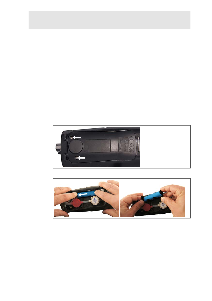
7 Maintaining the product
7 Maintaining the product
Pos: 100 /TD/Produkt instand halten/testo 330/test o 330 I nstandhaltung_Messgerät reinigen @ 6\mod_127926028 9656_79.docx @ 66679 @ 2 @ 1
7.1. Cleaning the measuring instrument
> If the housing of the measuring instrum ent is dirty, clean it with
a damp cloth. Do not use any aggressive cleaning agents or
solvents! Mild household cleaning agents and soap suds may
Pos: 101 /TD/Produkt instand halten/testo 320/test o 320 Pr odukt Instandhaltung_Akku @ 12\mod_1339577934470_ 79.docx @ 130753 @ 2333 @ 1
be used.
7.2. Replacing the rechargeable battery
✓ The measuring instrument must not be connected to a mains
socket via the mains unit. The instrum ent must be switched off.
Change the rechargeable battery within 2 minutes so that
instrument settings (e.g. date/time) are not lost.
1. Place the measuring instrument on its front.
2. Unscrew, lift up and remove the service cover.
3. Press down on the holder lightly with your fingers. Pull the
retaining clip in the direction o f the arrow until the catch is
released. Remove holder.
60
Page 61
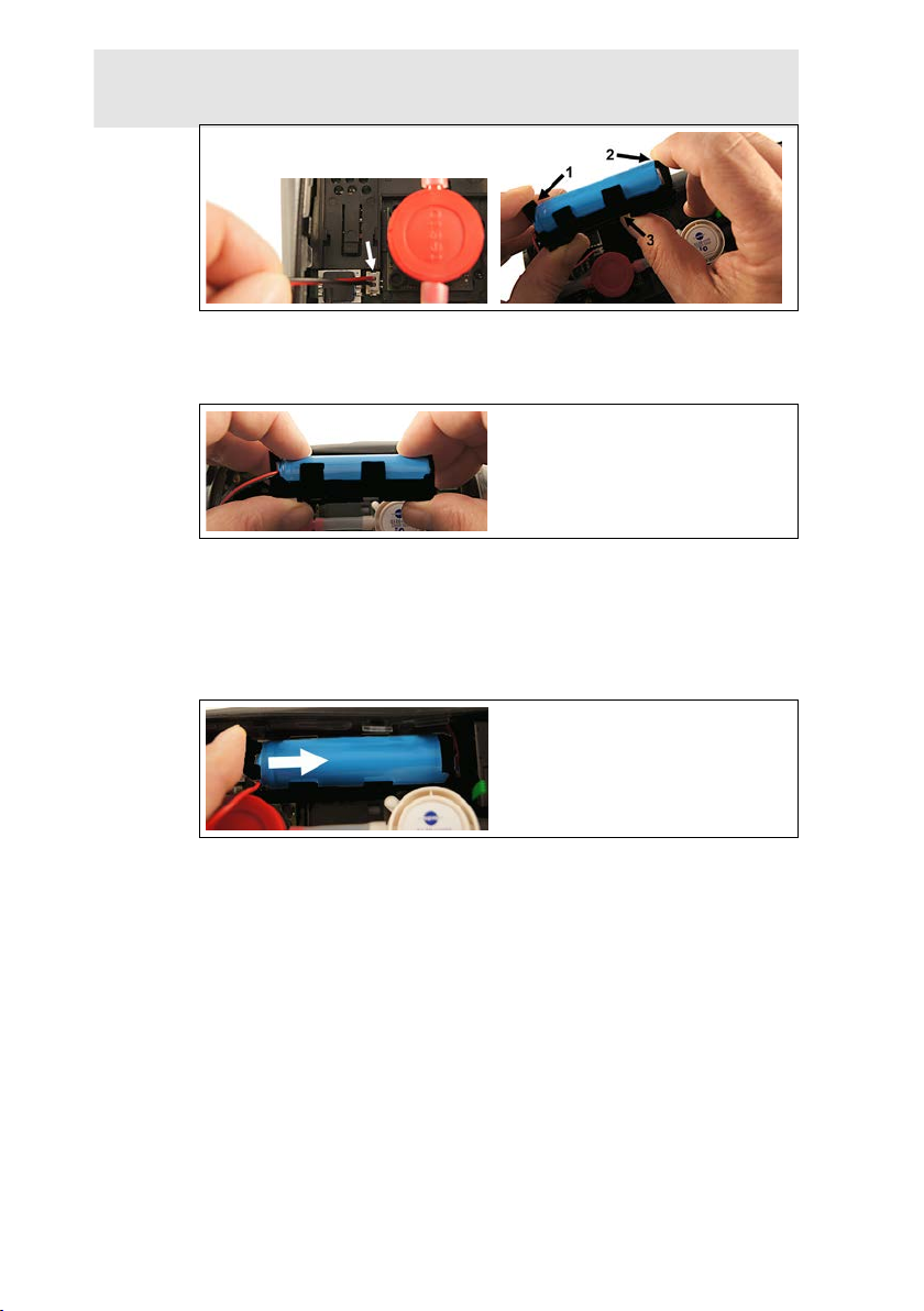
7 Maintaining the product
4. Unplug the plug-in connection from the slot.
5. Carefully pull the retaining clips (1, 2) outwards and p ush
rechargeable battery up and out of the holder (3).
6. Insert the new rechargeable battery in the holder. M ak e sure
that the plug-in connection cable is ro uted out of the holder at
the side. Press the rechargeable battery into the holder until the
retaining clips click into place.
7. Plug the new rechargeable battery plug-in connection into the
slot.
8. Insert the holder into the guide rail and slide it in the direction of
the arrow until the holder clicks into place.
9. Refit and close the service cover.
61
Page 62
7 Maintaining the product
7.3. Charging the battery
The rechargeable battery can only be charged at an ambient
temperature of ±0 to +35°C. If the rechar geable battery has been
completely discharged, the charging time at room temperature with
the testo mains unit is approx. 6 h.
Charging in the measuring instrument
1. Connect the mains unit instrument plug to the instrument's
micro USB socket.
2. Connect the mains plug of the mains unit to a mains socket.
- The c harging process will start. The chargin g process will stop
automatically when the batter y is fully charged.
Battery care
> Do not fully exhaust rechargeable batteries.
> Store rechargeable batteries only in charged condition and at
low temperatures, but not belo w 0°C (b est storage conditions
with a charge level of 50-80%, at an ambi ent temperature of
Pos: 102 /TD/Produkt instand halten/testo 320/test o 320 I nstandhaltung_Sensoren wechseln @ 11\mod_132741252 2161_79.docx @ 105320 @ 23 @ 1
10 - 20°C, recharge completely befor e us e).
7.4. Replacing sensors
✓ The measuring instrument must be switched off.
1. Place the measuring instrument on its front.
2. Unscrew, lift up and remove the service cover.
3. Disconnect the hose connections from the faulty sensor/bridge.
4. Remove the faulty sensor/bridge from the slot.
5. Install new sensor / new bridge in the slot.
6. Push the hose connections on to the sensor/bridge.
7. Refit and close the service cover.
After replacing an O2 sensor, wait f or an equalisation
period of 60 min to elapse before using the instrument
again.
When retrofitting a sensor, the assoc i ated measurement
parameter and unit must be enabled, see Sensor settings,
page 42.
62
Page 63
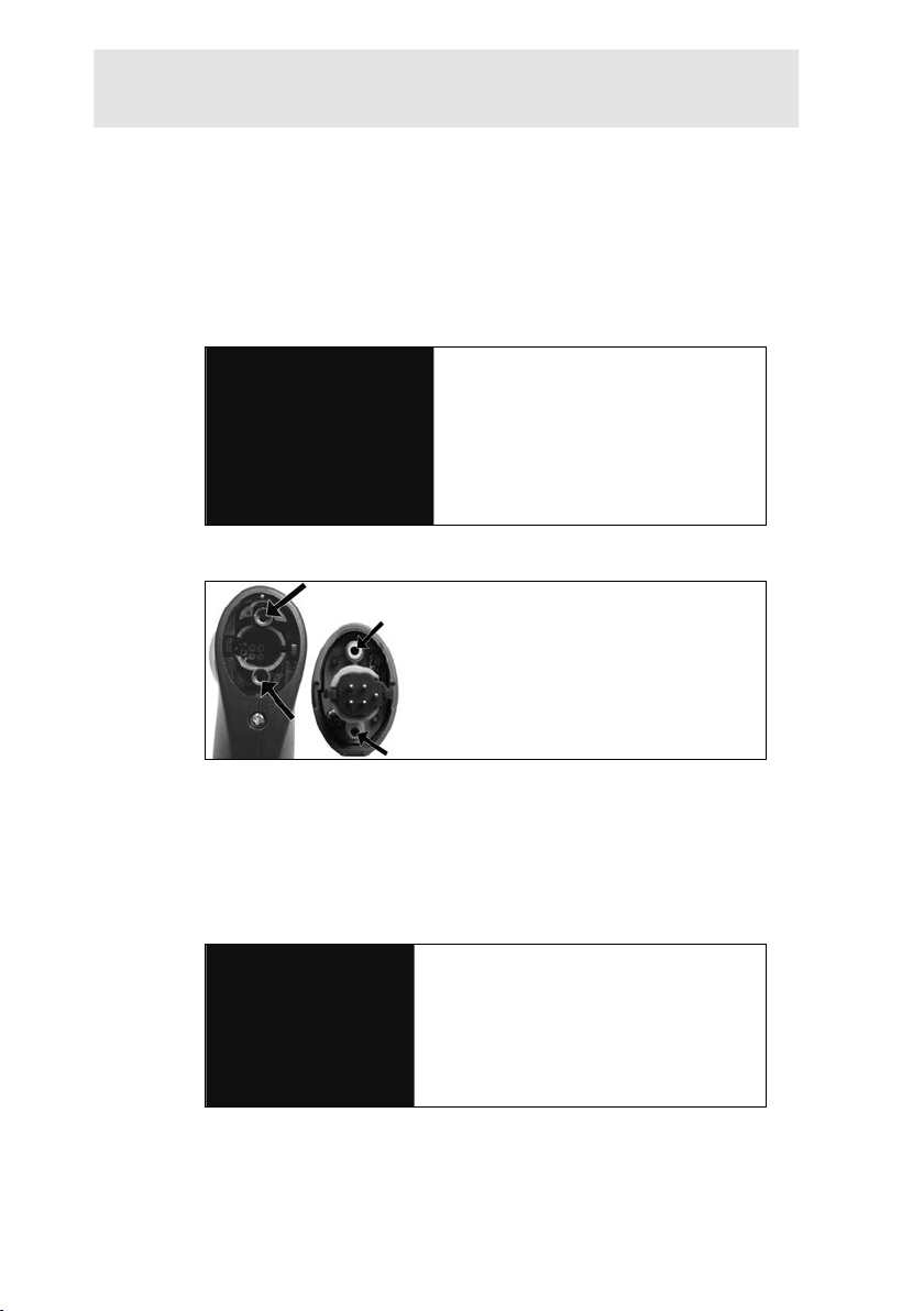
7.5. Recalibrating/adjusting sensors
Pos: 103 /TD/Produkt instand halten/testo 320/test o 320 Modulare Abgassonde reinigen, TE wechsel, Partikelf i lter @ 14\mod_1375269971876_79.docx @ 174476 @ 233333 @ 1
See Recalibration/adjustment, page 43.
7.6. Modular flue gas probe
7.6.1. Cleaning the flue gas ducts
✓ Disconnect the flue gas probe from the measuring instrument.
1. Release the probe catch by pressing the key on the probe
handle and remove the probe module.
7 Maintaining the product
2. Blow compressed air through the flue gas ducts in probe
module and probe handle (see illustration). Do not use a brush!
3. Fit a new probe module on the handle and engage in place.
7.6.2. Replacing the probe module
63
✓ Disconnect the flue gas probe from the measuring inst r ument.
1. Press the key on the top of the probe handle and remove th e
probe module.
2. Plug in the new probe module and engage it in place.
Page 64
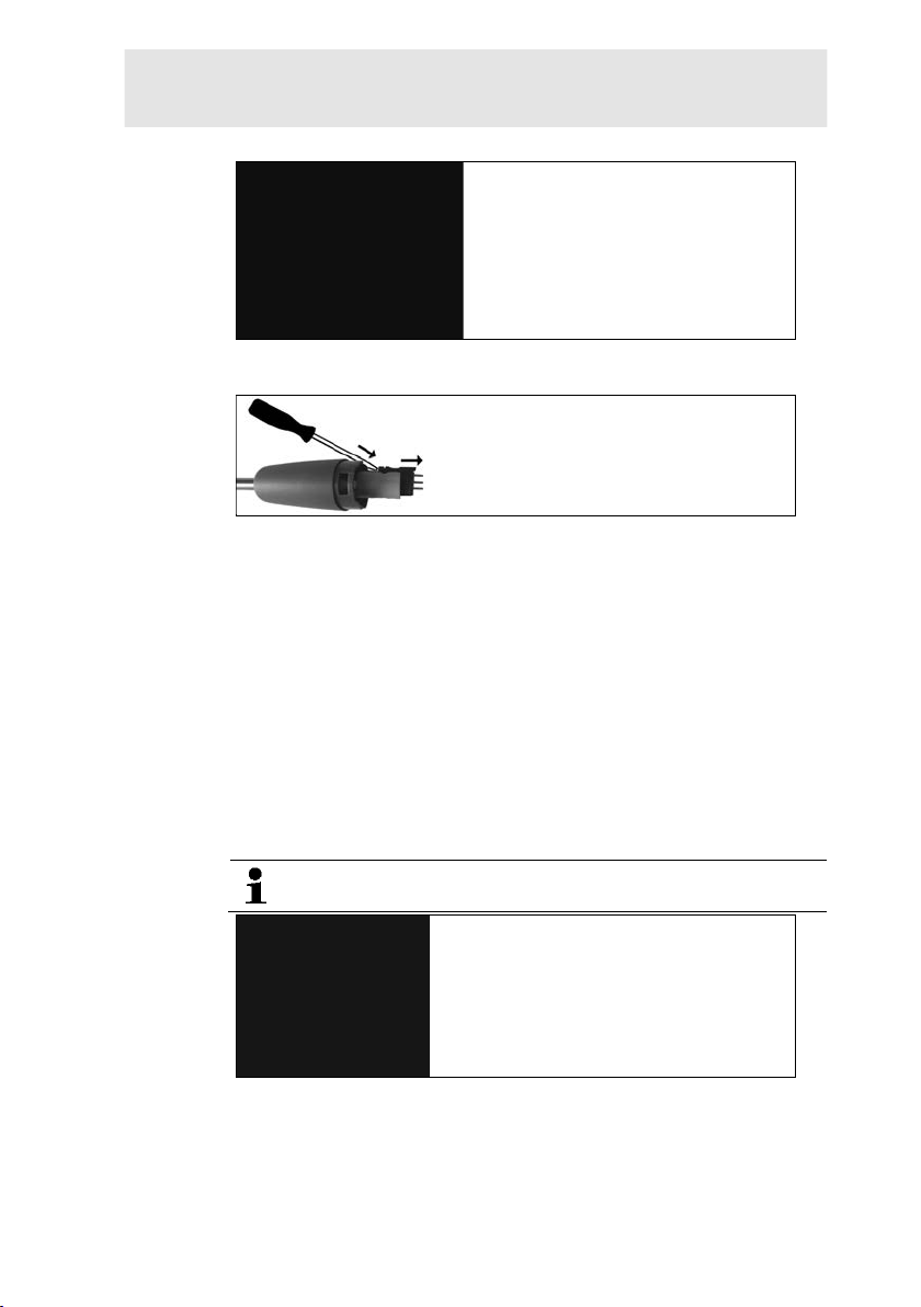
7 Maintaining the product
7.6.3. Replacing the thermocouple
1. Release the probe catch by pressing the key on the probe
handle and remove the probe module.
2. Remove the thermocouple plug-in head from the socket us i ng
a screwdriver and pull the thermocou pl e out of the probe shaft.
3. Keep inserting the new thermocouple into the probe s haft until
the connection head clicks into plac e.
4. Fit a new probe module on the handle and engage in place.
7.6.4. Checking the particle filter
> Check the particle filter of the modul ar flue gas probe regularly
for contamination: check visually by looking through the window
of the filter chamber.
Replace the filter if there are signs of c ontamination.
7.6.5. Replacing the particle filter:
The filter chamber may contain cond ensate.
1. Open the filter chamber: turn slightly anti-clockwise.
2. Remove the filter cartridge and replace it with a ne w one
(0554 3385).
3. Attach the filter chamber and lock it: turn slightl y clockwise.
64
Page 65
Pos: 104 /TD/Produkt instand halten/testo 320 basic/ testo 320 basic Kompakte Abgassonde reinigen, TE wechsel, Par ti k elfilter @ 14\mod_1375256927020_79.docx @ 173742 @ 1333 3 @ 1
7.7. Compact flue gas probe
7.7.1. Cleaning the probe shaft
✓ Disconnect the flue gas probe from the measuring instrument.
7 Maintaining the product
1. Loosen and remove halfshell handles (1).
2. Turn the sealing cap (2) clockwise as far as it will go and
remove probe shaft.
3. Blow compressed air through the probe shaft.
4. Replace the probe shaft and lock the sealing cap (2) by tightening
it anti-clockwise (as far as it will go, observe markings).
5. Replace halfshell handles and secure with screws.
7.7.2. Replacing the thermocouple
✓ Disconnect the flue gas probe from the measuring inst r ument.
65
Page 66
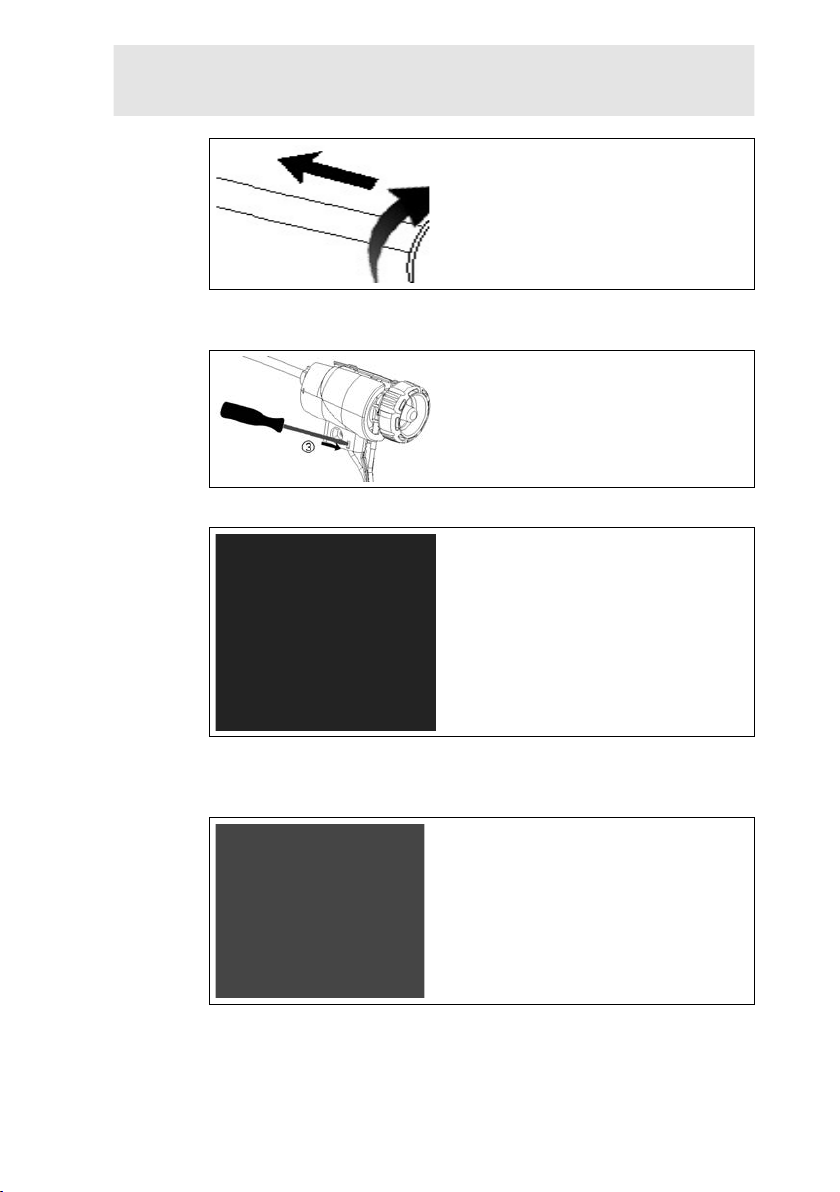
7 Maintaining the product
1. Loosen and remove halfshell handles (1).
2. Turn the sealing cap (2) clockwise as far as it will go and
remove probe shaft.
3. Release halfshell elements (3) and remove.
4. Remove the adapter (4) and hose (5), push the thermocou ple
out of its holder and disconnect the cable (6) from the
thermocouple.
5. Connect cables to the new thermocouple (white -, gr een +) (7)
and push the thermocouple back into t he holder.
66
Page 67
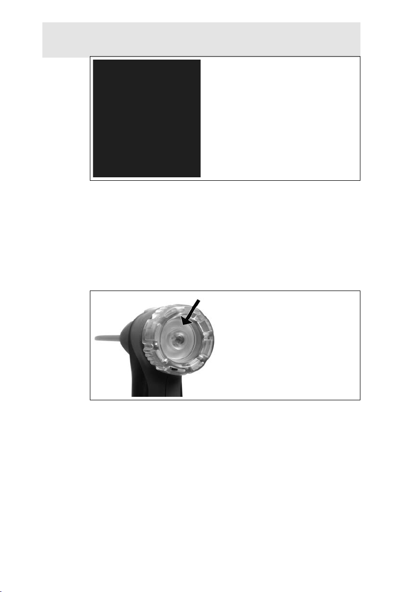
6. Connect the adapter and hose to the thermocouple (8). Adjust
cables and hoses (9), refit halfshell elements.
7. Replace the probe shaft and lock the sealing cap by tightening
it anti-clockwise (as far as it will go, observe markings).
8. Replace halfshell handles and secure with screws.
7.7.3. Checking the particle filter
> Check the particle filter of the compact flue gas probe regularly
for contamination:
7 Maintaining the product
> Carry out a visual inspection through the window in the filter
chamber.
- Replace the filter if there are any signs of contamination.
67
Page 68
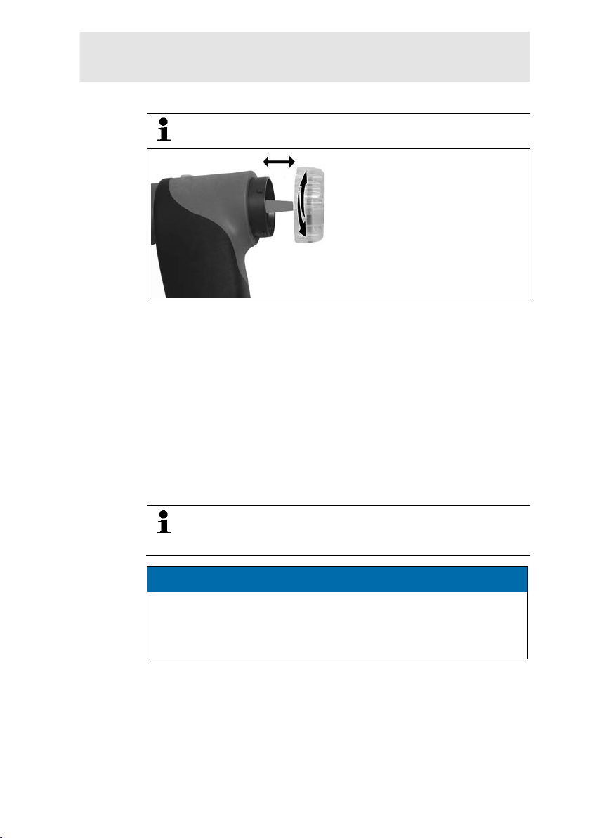
7 Maintaining the product
pump is in operation.
7.7.4. Replacing the particle filter
The filter chamber may contain cond ensate.
1. Open the filter chamber: turn slightly anti-clockwise.
2. Remove the filter cartridge and replace it with a ne w one
Pos: 105 /TD/Produkt instand halten/testo 320/test o 320_I nstandhaltung Kondensatbehälter @ 11\mod_1327 4133 54413_79.docx @ 105353 @ 23 @ 1
(0554 0040).
3. Attach the filter chamber and lock it: turn slightl y clockwise.
7.8. Condensate container
The fill level of the condensate contai ner can be read from the
markings on the condensate trap.
Draining the condensate container
The condensate consists of a weak mix of acids. Avoid skin
contact. Make sure that the condensate does not run over
the housing.
ATTENTION
Damage to the sensors and the flue gas pum p due to
condensate entering the gas path!
> Do not empty the condensate contain er while the flue gas
68
Page 69
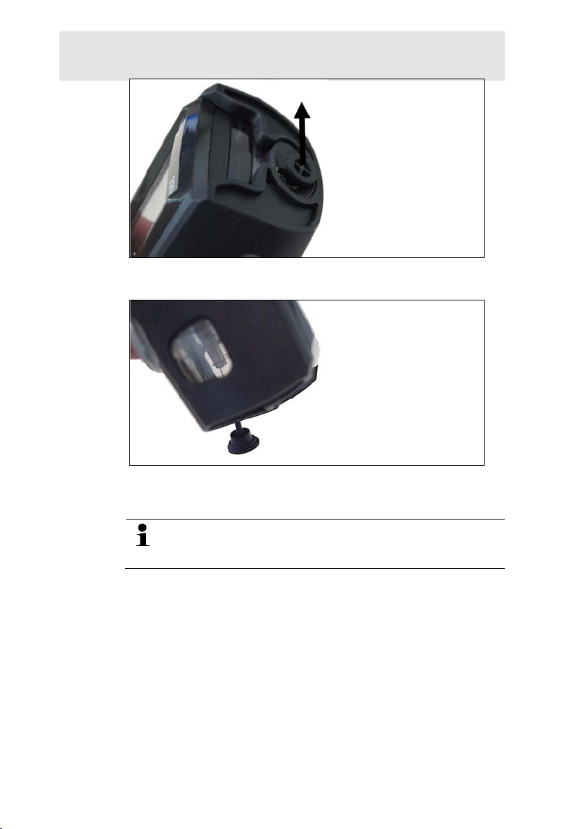
7 Maintaining the product
1. Open the condensate outlet on the condensate trap: Pull out
the plug as far as it will go.
2. Let the condensate run out into a sink.
3. Wipe off any drops still on the condensate outlet with a cloth
and close the condensate outlet.
The condensate outlet must be completely closed
(marking), otherwise measuring errors could be caused by
Pos: 106 /TD/Überschriften/8. Tipps und Hilfe @ 0\mod_11737 89887985_79.docx @ 406 @ 2 @ 1
69
infiltrated air.
Page 70

8 Tips and assistance
8 Tips and assistance
Pos: 107 /TD/Überschriften/8.1 Fragen und Antworten @ 0\m od_1 177402017078_79.docx @ 1093 @ 2 @ 1
8.1. Questions and answers
Pos: 108 /TD/Tipps und Hilfe/Fragen und Antworten/testo 3 20 Fragen und Anworten @ 11\mod_1327414318366_79.doc x @ 105419 @ @ 1
Question Possible causes/solution
Rechargeable battery low > Switch to mains operation.
Measuring instrument
switches off automatically
or cannot be switched on
Batteries/rechargeable batter ies
empty.
> Charge rechargeable battery or
switch to mains operation.
Error message: Cell
protection enabled
The shutdown limit of the CO sensor
was exceeded.
> Remove the probe from the stack.
Error message: Printing
not possible
• With printer 0554 0543: Bluetooth
interface not enabled.
• Wrong printer enabled.
• Printer switched off.
• Printer outside wireless
transmission range.
> Enable Bluetooth interfac e, see
Bluetooth
> Enable printer to be used.
> Switch on printer.
> Move printer into wireless
transmission range.
®
, page 41.
Pos: 109 /TD/Überschriften/8.3 Zubehör und Ersatztei le @ 0\mod_1177402058734_79.docx @ 1102 @ 5 @ 1
8.2.
Pos: 110 /TD/Tipps und Hilfe/Zubehör und Ersatzteile/ testo 320 Zuberhör_Ersatzteile @ 11\mod_132741407002 3_79.docx @ 105386 @ 5555555555 @ 1
Accessories and spare parts
Printer
Description Article no.
Infrared high-speed printer 0554 0549
Bluetooth® /IRDA printer, incl. Mains unit 5 V / 1.0 A
with micro USB cable
Mains unit 5 V / 1.0 A with micro USB cable 0554 1105
Spare thermal paper for printer (6 rolls) 0554 0568
70
0554 0620
Page 71
8 Tips and assistance
Mo
dular flue gas probes
Description Article no.
Modular flue gas probe 180mm, 500 °C,
thermocouple 0.5 mm, probe shaft diameter: 8 mm
Modular flue gas probe 300 mm, 500 °C,
thermocouple 0.5 mm, probe shaft diameter: 8 mm
Modular flue gas probe 180mm, 500 °C,
thermocouple 0.5 mm, probe shaft diameter: 6 mm
Modular flue gas probe 300 mm, 500 °C,
thermocouple 0.5 mm, probe shaft diameter: 6 mm
Flexible modular flue gas probe, length 330 mm,
Tmax. 180 °C, short-term 200 °C, bending radius
max. 90° for measurements at diffic ul t to access
locations
Compact flue gas probes
Description Article no.
Compact flue gas probe 180 mm, 500°C,
thermocouple 1.0 mm, probe shaft diameter: 6 mm
incl. cone
Compact flue gas probe 300mm, 500°C,
thermocouple 1.0 mm, probe shaft diameter: 6 mm
incl. cone
Flexible compact flue gas probe, length 330 mm,
Tmax. 180 °C, short-term 200 °C, bending radius
max. 90° for measurements at difficult to access
locations
0600 9760
0600 9761
0600 9762
0600 9763
0600 9770
0600 9740
0600 9741
0600 9742
Probe modules/accessories for modular flue gas probes
Description Article no.
Probe shaft module 180mm, 500°C, therm ocouple
0.5mm, probe shaft diameter: 8 mm
Probe shaft module 300mm, 500°C, therm ocouple
0.5mm, probe shaft diameter: 8 mm
Probe shaft module 180mm, 500°C, therm ocouple
0.5mm, probe shaft diameter: 6 mm
Probe shaft module 300mm, 500°C, therm ocouple
0.5mm, probe shaft diameter: 6 mm
0554 9760
0554 9761
0554 9762
0554 9763
71
Page 72
8 Tips and assistance
Probe shaft module 300 mm, 1000°C, thermocouple
1.0 mm, probe shaft diameter: 6 mm
Probe shaft module 700mm, 1000°C, t hermocouple
1.0 mm, probe shaft diameter: 6 mm
Spare thermocouple for module 05 54 9760,
0554 9762
Spare thermocouple for module 05 54 9761,
0554 9763
Spare thermocouple for module 05 54 8764 0430 8764
Spare thermocouple for module 05 54 8765 0430 8765
Cone, 8mm, steel 0554 3330
Cone, 6mm, steel 0554 3329
Multi-hole probe shaft, length 300 mm, Ø 8 mm, for
CO averaging
Multi-hole probe shaft, length 180 mm, Ø 8 mm, for
CO averaging
Flexible probe shaft module 0554 9770
Hose extension 2.8 m, extension line probe -
instrument
Particle filter for modular flue gas probe, 10 pieces 0554 3385
0554 8764
0554 8765
0430 9760
0430 9761
0554 5762
0554 5763
0554 1202
72
Probe modules/accessories for compact flue gas probes
Description Article no.
Spare thermocouple for 0600 9740 0430 0383
Spare thermocouple for 0600 9741 0430 0382
Particle filter for compact flue gas probe, 10 pieces 0554 0040
Temperature probe
Description Article no.
Combustion air temperature probe, 300mm 0600 9791
Combustion air temperature probe, 190mm 0600 9787
Combustion air temperature probe, 60m m 0600 9797
Fast reaction surface sensor 0604 0194
Miniature ambient air sensor 0600 3692
Page 73
8 Tips and assistance
Ot
her probes
Description Article no.
O2 annular gap probe 0632 1260
Gas leak probe 0632 3330
Ambient CO probe 0632 3331
CO2 ambient probe (without connec ting cable) 0632 1240
Connecting cable for CO2 ambient pr obe, 1.5 m 0430 0143
Gas pressure set: Draught path adapter , silicone
hose 4 mm / 6 mm, reducing cones
Smoke tester incl. oil, soot plates, for measuring
soot in flue gas
Spare sensors
Description Article no.
O2 sensor 0393 0005
CO sensor 0393 0053
CO sensor H2-compensated 0393 0105
COlow sensor 0393 0103
0554 1203
0554 0307
Cases
System case with double floor (height:180 mm) for
instrument, probes and accessories
System case (height: 130 mm) for instrument,
probes and accessories
System case with tool pouch without contents 0516 0329
Other accessories
Description Article no.
Mains unit incl. micro USB cable 0554 1105
Spare rechargeable battery 0515 0046
Readout adapter for automatic fur nac es 0554 1206
Connecting cable instrument / PC 0449 0047
Easyheat (PC configuration sof tware) 0554 3332
Draught set 0554 3150
0516 3301
0516 3300
73
Page 74

8 Tips and assistance
Description Article no.
External micro pressure probe 0638 0330
Set of capillary hoses 0554 1215
Solid fuel measurement module with adapter and
probe shaft with sintered filter
Sintered filter for solid fuel measurement probe shaft 0133 0035
Filter material for condensate tr ap on solid fuel
measurement adapter
Adhesive kits (x50) for printouts, paper barcode
labels etc.
Straight Pitot tube 0635 2050
ISO Calibration Certificate Flu e Gas 0520 0003
Pos: 111 /TD/Tipps und Hilfe/testo 320 Instandhaltung Update Firmware @ 12\mod_1337944150042_79.doc x @ 124943 @ 2 @ 1
8.3. Updating the instrument software
0600 9765
0133 0012
0554 0116
> Unplug the micro USB cable and switch off the testo 320.
1. Hold down [▲].
2. Reconnect the micro USB m ains cable to the testo 320,
continue holding down [▲].
- The display shows Firmware update along the bottom edge.
3. Release [▲].
- Your PC recognises the test o 320 as a removable medium.
4. Copy the new file (ap32 0rel.bin) to the detected removabl e
medium.
- On the display the status bar pr ogresses from left to right. This
process may take a few minutes.
- Once the instrument software (firmware) has been updated, the
system will automatically rebo ot and is ready for use.
=== Ende der Liste für Textmarke Inhalt ===
5. Disconnect the connecting cable from the testo 320.
Test Equipment Depot - 800.517.8431 - 99 Washington Street Melrose, MA 02176
TestEquipmentDepot.com
74
 Loading...