

Page 1
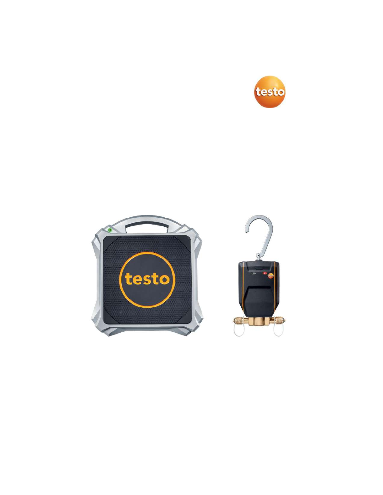
testo 560i and testo Smart Valve
0564 1560
0560 5600
Instruction manual
Find Quality Products Online at: [email protected]
www.GlobalTestSupply.com
Page 2

Page 3

Contents
Contents
1 About this document ........................................................................... 3
2 Safety and disposal .............................................................................. 3
3 Product-specific approvals ................................................................. 3
4 Product-specific information............................................................... 4
5 Intended use ......................................................................................... 5
6 Product description ............................................................................. 6
6.1 Overview of testo 560i ............................................................................ 6
6.2 Overview of testo Smart Valve ............................................................... 7
7 First steps ................................ ............................................................. 8
7.1 Inserting batteries ................................................................................... 8
7.2 Switching the instrument on and off ....................................................... 9
7.3 Establishing a Bluetooth® connection ................................................... 10
7.3.1 Establishing a Bluetooth® connection to the testo Smart App .............. 10
7.3.2 Establishing a Bluetooth® connection to the testo 550s / testo 557s
manifold ................................................................................................ 11
7.3.2.1 Switching on ......................................................................................... 11
7.3.2.2 Switching off ......................................................................................... 12
8 Using the product ............................................................................... 13
8.1 Control via manifold .............................................................................. 14
8.2 Connecting the instruments .................................................................. 15
8.3 Manual charging via weight .................................................................. 16
8.4 Automatic charging by target weight .................................................... 18
8.5 Automatic charging by superheat ......................................................... 22
8.6 Automatic charging by subcooling ........................................................ 25
8.7 Automatic charging via target superheat .............................................. 28
8.8 Control via app ..................................................................................... 32
8.8.1 Creating and editing a customer .......................................................... 34
8.8.2 Creating and editing measuring sites ................................................... 35
8.8.3 Searching for and deleting measurement results ................................. 36
8.8.4 Sensors ................................................................................................ 37
8.8.4.1 Information ........................................................................................... 37
8.8.4.2 Settings ................................................................................................ 38
8.8.5 Language ............................................................................................. 38
8.8.6 Measurement settings .......................................................................... 38
8.8.7 Company details................................................................................... 39
8.8.8 Privacy settings .................................................................................... 39
8.8.9 Help and Information ............................................................................ 40
Find Quality Products Online at: [email protected]
www.GlobalTestSupply.com
Page 4

Contents
8.8.9.1 Instrument information ......................................................................... 40
8.8.9.2 Tutorial ................................................................................................. 40
8.8.9.3 Exclusion of liability .............................................................................. 40
9 Maintenance ....................................................................................... 41
9.1 Calibration ........................................................................................... 41
9.2 Cleaning instruments ........................................................................... 41
9.3 Keeping connections clean .................................................................. 41
9.4 Removing oil residues ......................................................................... 41
9.5 Ensuring measuring accuracy.............................................................. 41
9.6 Changing batteries ............................................................................... 42
10 Technical data ................................ ................................ .................... 43
10.1 Technical data for testo 560i ................................................................ 43
10.2 Technical data for testo Smart Valve ................................................... 44
11 Tips and assistance ........................................................................... 44
11.1 Accessories ......................................................................................... 44
12 Support ............................................................................................... 44
Find Quality Products Online at: [email protected]
www.GlobalTestSupply.com
Page 5
1 About this document
3
1 About this document
• The instruction manual is an integral part of the instrument.
• Pay particular attention to the safety instructions and warning advice in order
to prevent injury and damage to the product.
• Please read this instruction manual through carefully and familiarize yourself
with the product before putting it to use.
• Familiarity with a PC as well as the Microsoft® products is assumed in this
documentation.
Symbols and writing standards
Display
Explanation
Note: basic or further information
Warning advice, risk level according to the signal word:
Warning! Serious physical injury may occur.
Caution! Minor physical injury or damage to the equipment may
occur.
Careful! Possible damage to equipment.
- Implement the specified precautionary measures.
1
2
…
Action: several steps, the sequence must be followed
Result of an action
✓
Requirement
Menu
Elements of the instrument, the instrument display or the
program interface.
[OK]
Control keys of the instrument or buttons of the program
interface.
2 Safety and disposal
Please observe the Testo information document (enclosed with the product).
3 Product-specific approvals
For the relevant country approvals, please refer to the printed quick reference
guides or short instructions enclosed with the products.
Find Quality Products Online at: [email protected]
www.GlobalTestSupply.com
Page 6

4 Product-specific information
4
4 Product-specific information
• The instrument being dropped or any other comparable mechanical stress
may result in breakage of the pipe sections in the refrigerant hoses. The
valve positioners may also suffer damage, causing further damage inside
the measuring instrument that is not necessarily visible externally. Therefore,
always replace the refrigerant hoses with new ones after the measuring
instrument is dropped or after any comparable mechanical stress. For your
own safety, return the instrument to Testo Customer Service for technical
inspection.
• Electrostatic charging may destroy the instrument. Integrate all the
components (system, manifold’s valve block, refrigerant bottle, etc.) into the
equipotential bonding (earthing). Please see the safety instructions for the
system and the refrigerant used.
• Refrigerant gases can harm the environment. Please note the applicable
environmental regulations.
• Use with A2L refrigerants
Testo measuring instruments (as of July 2020) can be used in compliance
with the prescribed laws, standards, directives and safety regulations for
refrigeration systems and refrigerants as well as regulations of the
manufacturers of refrigerants of safety group A2L as per ISO 817.
Regional standardization and interpretation must always be observed.
For example, DIN EN 378-Part 1-4 applies to the scope of the EN standards.
During maintenance work, the employer must ensure that a hazardous
explosive atmosphere is prevented (see also TRBS1112, TRBS2152 VDMA
24020-3).
A hazardous and potentially explosive atmosphere must be anticipated
during maintenance and repair work on refrigeration systems with flammable
refrigerants (e.g. those in category A2L and A3).
Maintenance, repairs, removal of refrigerants and commissioning of systems
may only be carried out by qualified personnel.
Find Quality Products Online at: [email protected]
www.GlobalTestSupply.com
Page 7
5 Intended use
5
5 Intended use
The testo 560i scale and the testo Smart Valve are aids for carrying out
maintenance and service work on refrigeration systems and heat pumps. They
may only be used by qualified authorized personnel.
Via their functions, the instruments help with charging refrigeration systems and
heat pumps.
The testo 560i and testo Smart Valve can be used either in conjunction with
the testo Smart App or in conjunction with one of the testo 550s and testo 557s
manifolds.
The testo Smart Valve is compatible with most non-corrosive refrigerants,
water and glycol. The testo Smart Valve is not compatible with refrigerants
containing ammonia.
The products are suitable for gaseous charging of refrigeration systems.
When charging with liquid refrigerant, an evaporation adapter must be used to
protect the compressor or the flow rate limited via the manifold.
ATTENTION
Charging liquid refrigerant too quickly can damage the compressor!
- Only charge liquid refrigerant slowly.
The products must not be used in potentially explosive atmospheres!
The testo Smart Valve must not be used in the vicinity of a magnetic field.
ATTENTION
Danger due to leaking refrigerant.
The testo Smart Valve does not constitute a safety mechanism.
- Stop the flow of refrigerant at the refrigerant bottle once the
charging process has been completed.
- Always stop the flow of refrigerant from the refrigerant bottle to the
testo Smart Valve when not in use.
Always hang the testo Smart Valve up straight using the hook and
make sure that the scale and the valve are always level/horizontal.
Find Quality Products Online at: [email protected]
www.GlobalTestSupply.com
Page 8
6 Product description
6
6 Product description
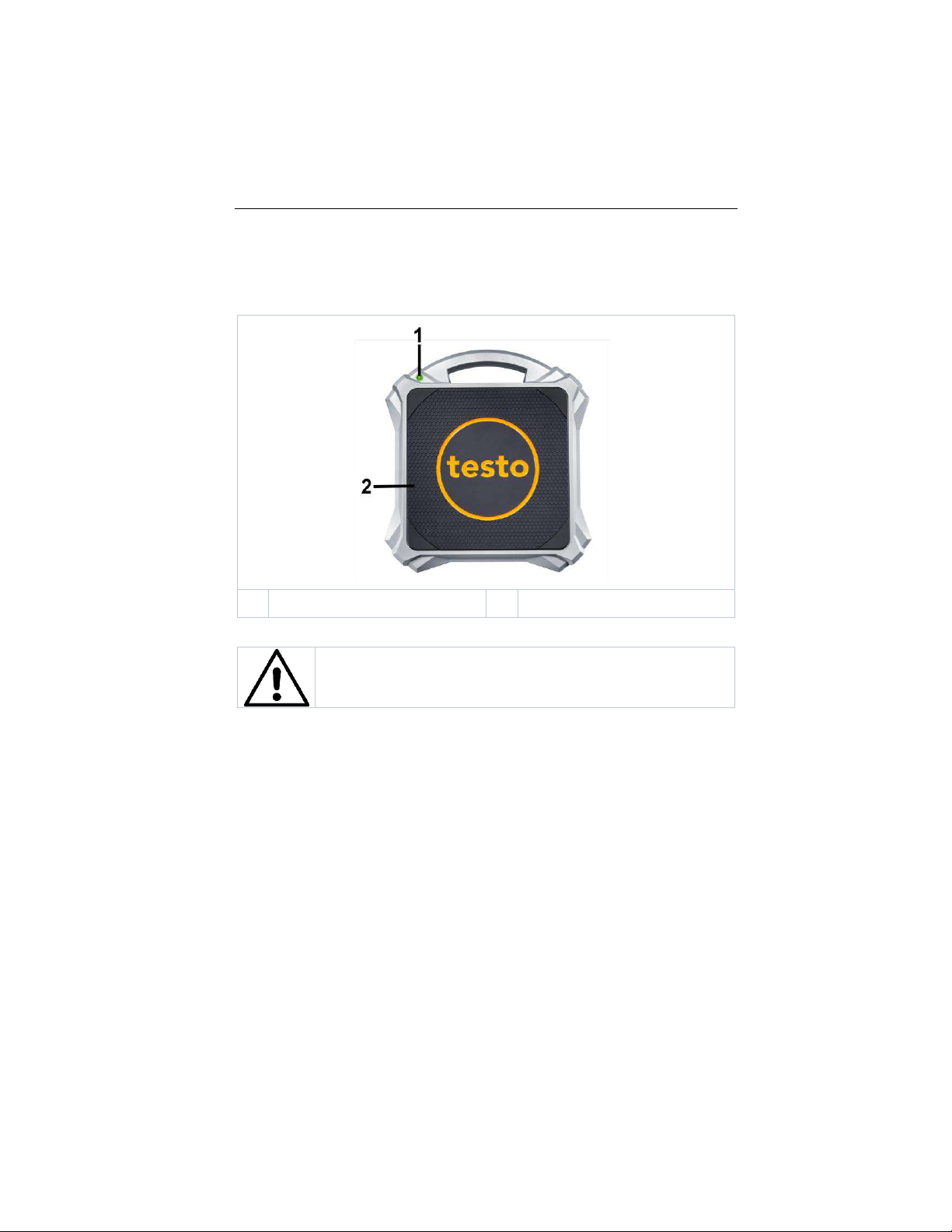
6.1 Overview of testo 560i
1
On/off switch
2
Battery compartment (on rear)
Symbol explanation
Observe operating instructions
Find Quality Products Online at: [email protected]
www.GlobalTestSupply.com
Page 9
6 Product description
7
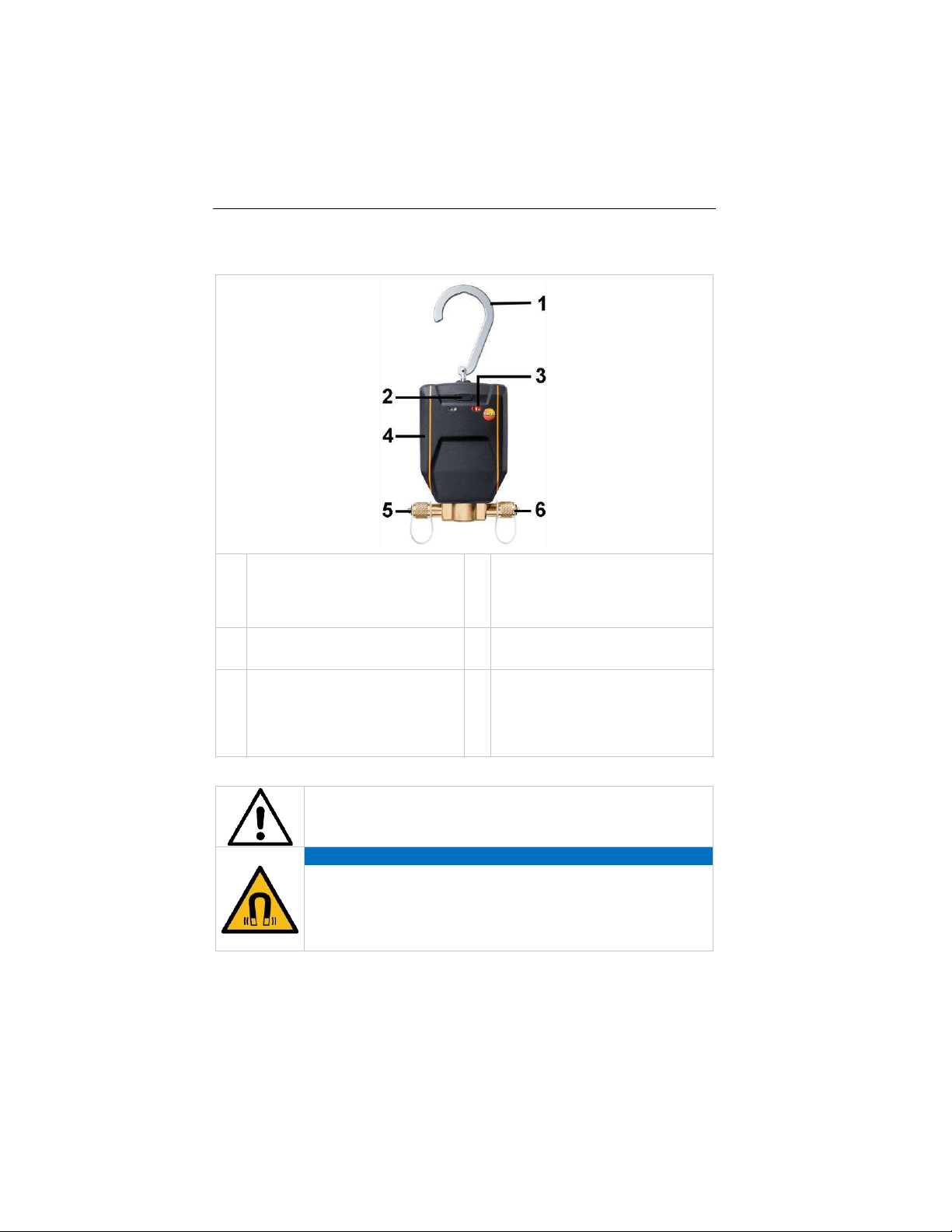
6.2 Overview of testo Smart Valve
1
Folding suspension device (rear)
2
On/off switch
- 1x click: Switch on
- Hold down: Switch off
- 3x clicks: Open valve for 1 s
3
Status LED
- Constant red: Valve open
4
Battery compartment (on rear)
5
Refrigerant outlet: Connection
7/16" UNF, brass. For refrigerant
hoses with quick-release fitting,
passage can be closed via valve
positioner.
6
Refrigerant inlet: Connection
7/16" UNF, brass. For refrigerant
hoses with quick-release fitting,
passage can be closed via valve
positioner.
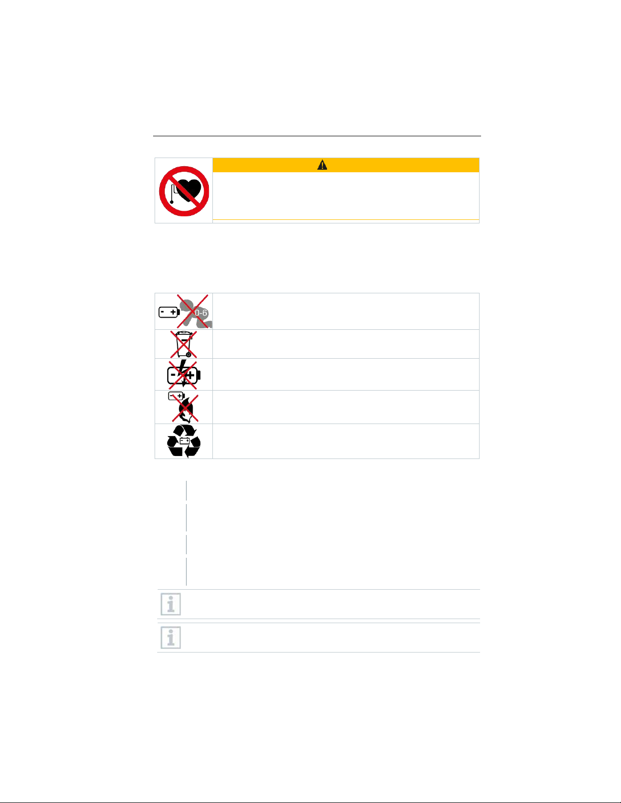
Symbol explanation
Observe operating instructions
ATTENTION
Magnetic field
Damage to other devices!
- Keep a safe distance from products that can be
damaged by magnetism (e.g. monitors, computers,
credit cards).
Find Quality Products Online at: [email protected]
www.GlobalTestSupply.com
Page 10
7 First steps
8
WARNING
Magnetic field
May be hazardous to the health of pacemaker wearers.
- Keep a minimum distance of 15 cm between the
pacemaker and the device.
7 First steps
7.1 Inserting batteries
Symbol explanation
Do not allow children under 6 years of age to play with batteries.
Do not throw batteries in the trash.
Do not charge batteries.
Do not place batteries near fire.
Batteries are recyclable.
Inserting batteries in the testo 560i
1
Open battery compartment.
2
Insert the batteries (scope of delivery) into the battery compartment.
Observe the polarity!
3
Close the battery compartment.
After inserting the batteries, the instrument switches on automatically
and is in Bluetooth® connection mode.
In Bluetooth® connection mode, connection can be established to the
testo Smart App or to a testo 550s or testo 557s manifold.
Do not change or remove batteries during operation, otherwise the
charging process will be interrupted.
Find Quality Products Online at: [email protected]
www.GlobalTestSupply.com
Page 11

7 First steps
9
When not in use for a long period: Take out the batteries.
Inserting batteries in the testo Smart Valve
1
Unfold the suspension hook and open the battery compartment (clip
lock).
2
Insert the battery (supplied, block battery) into the battery
compartment. Observe the polarity!
3
Close the battery compartment.
After inserting the batteries, the instrument switches on automatically
and is in Bluetooth® connection mode.
In Bluetooth® connection mode, connection can be established to the
testo Smart App or to a testo 550s or testo 557s manifold.
Do not change or remove batteries during operation, otherwise the
charging process will be interrupted.
When not in use for a long period: Take out the batteries.
7.2 Switching the instrument on and off
Switching on testo 560i
1
Press the ON key.
The instrument switches on and is in Bluetooth® connection mode.
In Bluetooth® connection mode, connection can be established to the
testo Smart App or to a testo 550s or testo 557s manifold.
2
Press and hold the ON key.
The instrument is switched off.
Find Quality Products Online at: [email protected]
www.GlobalTestSupply.com
Page 12
7 First steps
10
Switching on Testo Smart Valve
✓
Do not switch on Testo Smart Valve until all hoses have been
attached and the installation is ready for charging.
1
Press the ON key.
The instrument switches on and is in Bluetooth® connection mode.
In Bluetooth® connection mode, connection can be established to the
testo Smart App or to a testo 550s or testo 557s manifold.
2
Press and hold the ON key.
The instrument is switched off.
7.3 Establishing a Bluetooth® connection
✓
The testo 560i scale or the testo Smart Valve are switched on.
7.3.1 Establishing a Bluetooth® connection to the testo Smart App
To establish a connection via Bluetooth®, you need a tablet or
smartphone with the Testo Smart App already installed on it.
You can obtain the app for iOS devices from the App
Store, for Android devices from the Play Store or by
scanning the QR code in the manifold.
Compatibility:
Requires iOS 12.0 or later/Android 6.0 or later, requires Bluetooth® 4.0.
1
Open Testo Smart App.
The app automatically searches for Bluetooth® devices in the vicinity.
2
In the Bluetooth menu, check whether the required instrument is
connected.
If necessary, switch the instrument to be connected off and on again
to restart the connection mode.
Find Quality Products Online at: [email protected]
www.GlobalTestSupply.com
Page 13
7 First steps
11
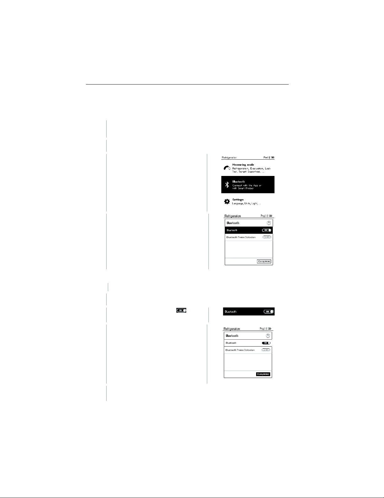
7.3.2 Establishing a Bluetooth® connection to the testo 550s / testo 557s manifold
✓
The instrument is switched on and the measurement menu is
displayed.
1
Press [Menu/Enter].
2
Use [▲] / [▼] to select Bluetooth
and [Menu/Enter] to confirm.
The Bluetooth menu is displayed.
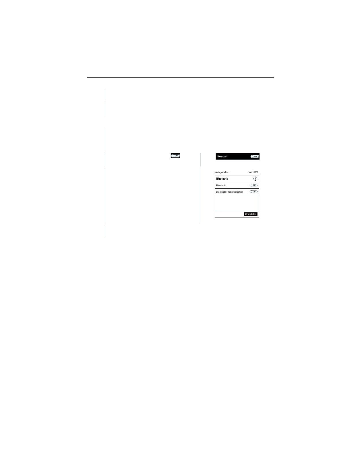
7.3.2.1 Switching on
✓
The Bluetooth menu is selected.
1
[Menu/Enter]
In the On/Off switch icon, is
displayed.
2
Enable Bluetooth®: Use [▼] to
activate the [Completed] button and
[Menu/Enter] to confirm.
When the Bluetooth® icon appears on the display, Bluetooth® is
switched on.
Find Quality Products Online at: [email protected]
www.GlobalTestSupply.com
Page 14
7 First steps
12
Bluetooth® automatically searches for and connects available devices.
If necessary, switch the instrument to be connected off and on again
to restart the connection mode.
7.3.2.2 Switching off
✓
The Bluetooth® menu is activated.
1
[Menu/Enter]
In the On/Off switch icon, is
displayed.
3
Disable Bluetooth®: Use [▼] to
activate the [Completed] button and
[Menu/Enter] to confirm.
When the Bluetooth® icon is not shown on the display, Bluetooth® is
switched off.
Find Quality Products Online at: [email protected]
www.GlobalTestSupply.com
Page 15
8 Using the product
13
8 Using the product
The testo 560i scale and the testo Smart Valve can either be used in
conjunction with the testo Smart App or in conjunction with one of the testo
550s and testo 557s manifolds or with two testo 549i smart probes.
This product is suitable for gaseous charging of refrigeration systems.
When charging with liquid refrigerant, an evaporation adapter must be
used to protect the compressor or the flow rate limited via the manifold.
The valve opens and attempts to fill with the set charge quantity. When
charging by target weight, no pulsating charging takes place.
The suitable filling mode must be selected individually based on the
AC system which needs to be filled.
ATTENTION
Charging liquid refrigerant too quickly can damage the compressor!
- Only charge liquid refrigerant slowly.
It is necessary to enter the maximum capacity of the system to prevent
overcharging.
If unsure of total charge and information about the system is
unavailable, reclaim all refrigerant.
If the refrigerant bottle is empty and needs to be replaced with a new
one, the value of the previously filled quantity must be noted down.
Despite automation, the system can be overcharged. Reasons for this
may be due to specific local or system-specific conditions. The
technician must always monitor the automatic charging.
If the superheat cannot be measured (display shows xx° superheat),
then automatic charging cannot be started. Measuring the superheat
forms the basis for automatic charging.
Generally, charging stops in the following situations:
• The weight on the scale changes suddenly or involuntarily.
• The maximum charge quantity has been reached, although the final
value (SH/SC) has not yet been reached.
Find Quality Products Online at: [email protected]
www.GlobalTestSupply.com
Page 16
8 Using the product
14
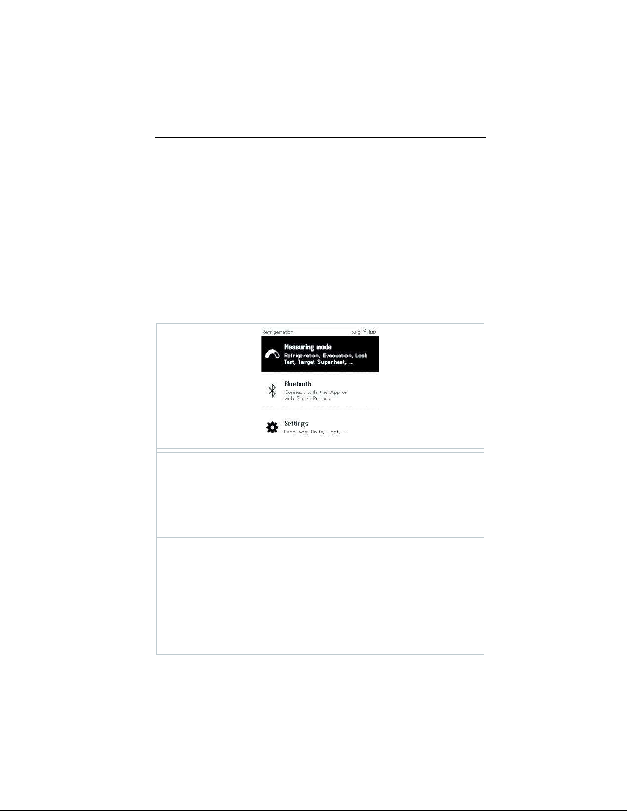
8.1 Control via manifold
✓
Scale and valve are switched on.
✓
The manifold is switched on and connected to the valve and scale via
Bluetooth®.
✓
The firmware of the manifold is up to date.
The firmware is updated by downloading the latest testo Smart App
from the App Store or Play Store.
Settings and controls are implemented via the manifold.
Manifold main menu
Measuring mode
Refrigeration
Evacuation
System Leak Test
Target Superheat
Compressor Test (DLT)
Delta T
Refrigerant Filling
Bluetooth®
Connection to the testo Smart App or Smart Probes
Settings
Backlight duration
Backlight brightness
Auto Off
Auto Tfac (Temperature compensation factor)
Units
Language
Setup Wizard
Restore factory settings
Instrument information
Find Quality Products Online at: [email protected]
www.GlobalTestSupply.com
Page 17
8 Using the product
15
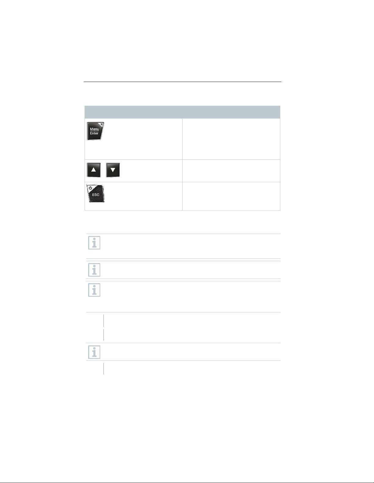
Manifold control keys
Symbol
Meaning
- Open menu
- Confirm input
- Switch on the display illumination:
Press and hold the key for >2s
- Switch off the display illumination:
Press and hold the key for >2s
/
Change/navigate the display screen.
- Switches to the measurement view
- Back to the menu
- Switch off the instrument: Press
and hold the key for >2s
8.2 Connecting the instruments
Before each use, make sure that the refrigerant hoses are in flawless
condition.
Observe the system's maximum permitted operating pressure.
Do not switch on the testo Smart Valve until all hoses have been
attached and the installation is ready for charging.
Protect the testo Smart Valve from vibrations. Otherwise, safe opening
and closing cannot be guaranteed.
If the testo Smart Valve is subjected to a hard impact or a fall, it must
be switched on and off again. Otherwise, the valve position may be lost.
✓
All connections must be pressureless (ambient pressure).
1
Place refrigerant bottle on scale.
Make sure that there is always enough refrigerant in the bottle so that
the charging process can be carried out correctly.
2
Connect refrigerant bottle to valve.
Find Quality Products Online at: [email protected]
www.GlobalTestSupply.com
Page 18

8 Using the product
16
3.1
From the valve, connect the yellow refrigerant hose to the middle port
of the manifold and connect the low pressure side (blue) and high
pressure side (red) of the manifold to the system.
Pay attention to the refrigerant flow direction. This is indicated by an
arrow on the valve.
3.2
When using the app, connect the valve directly to the system with
refrigerant hoses, without the manifold.
Ensure hoses are filled with refrigerant prior to opening valves into a
system to eliminate air from entering the system.
3.3
Click 3 times on on/off button to open the valve for 1 second and fill
the hoses with refrigerant.
8.3 Manual charging via weight
This function enables a refrigerant circuit to be charged manually via weight
using the testo 560i in combination with the app or testo 550s / testo 557s
manifold.
By manually opening and closing the refrigerant bottle valve, the system is
charged with refrigerant until the target value (weight/superheating/subcooling)
is reached.
Displaying the current target values superheating/subcooling is only
possible in combination with testo 115i smart probes.
When using the manifold, the app is in second-screen mode. All
settings must be made on the manifold.
Before each measurement, check that the refrigerant hoses are in
flawless condition and applied to all ports tight to prevent leaks.
The system must be supervised by a competent person throughout the
entire process.
✓
testo 560i is connected via Bluetooth to the testo Smart App or the
testo 550s / testo 557s manifold.
✓
testo 560i is integrated into the refrigerant circuit.
1
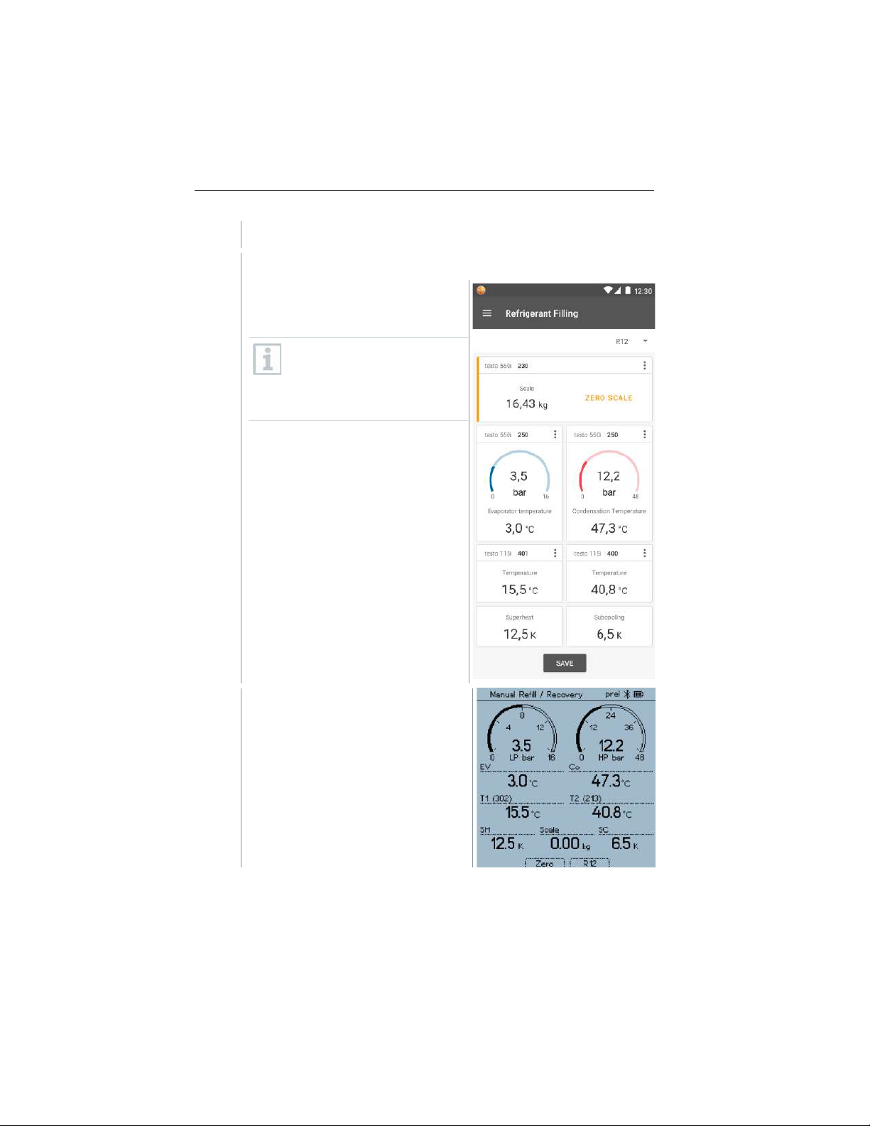
Select the required refrigerant on the manifold/app and press
[Menu/Enter] to confirm.
Find Quality Products Online at: [email protected]
www.GlobalTestSupply.com
Page 19
8 Using the product
17
1.1
If necessary, zero sensor on manifold/app [P = 0].
1.2
If necessary, zero testo 560i on manifold/app [W = 0].
2
Open connected valve(s) manually
and add refrigerant to the system
until the required value is reached.
Charging manually means the
user will need to control the
charge by opening and closing
valves with a manifold or other
valves.
Added refrigerant is displayed in g/kg
increments on the manifold/app.
Find Quality Products Online at: [email protected]
www.GlobalTestSupply.com
Page 20

8 Using the product
18
8.4 Automatic charging by target weight
This function enables the system to be charged automatically with an input
target weight using the testo 560i scale and the testo Smart Valve in
combination with the app or the testo 550s / testo 557s manifold.
When using the manifold, the app is in second-screen mode. All
settings must be made on the manifold.
Before each measurement, check that the refrigerant hoses are in
flawless condition and applied to all ports tight to prevent leaks.
The system must be supervised by a competent person throughout the
entire process.
✓
testo 560i and testo Smart Valve are connected via Bluetooth to the
testo Smart App or the testo 550s / testo 557s manifold.
✓
testo 560i and testo Smart Valve are integrated into the refrigerant
circuit.
1
Select the required refrigerant on the manifold/app and press
[Menu/Enter] to confirm.
1.1
If necessary, zero sensor on manifold/app [P = 0].
Find Quality Products Online at: [email protected]
www.GlobalTestSupply.com
Page 21
8 Using the product
19
2
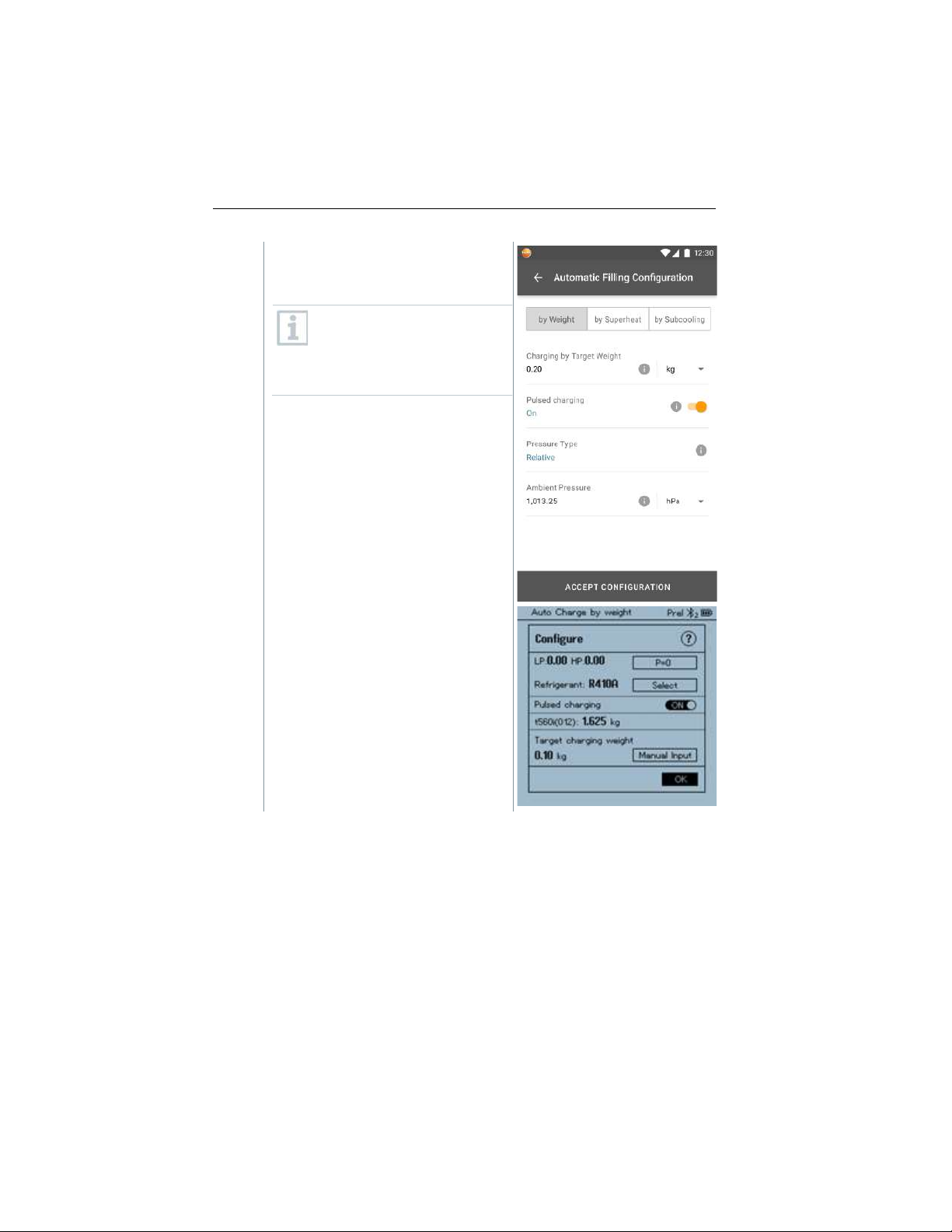
- In the manifold/app, select the proper
refrigerant and select if pulsed
charging is desired (on/off).
Pulsed charging means that
the valve opens and closes
several times and the desired
amount is thus filled in several
small steps.
Find Quality Products Online at: [email protected]
www.GlobalTestSupply.com
Page 22
8 Using the product
20
3
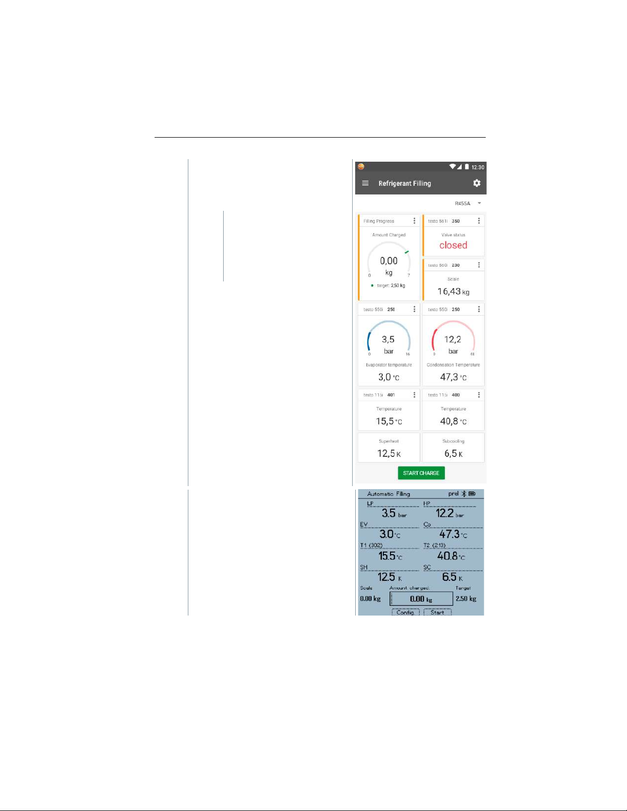
Enter Target Weight by selecting
manual input and hit
[START CHARGE] to start the
process.
The valve opens and
attempts to fill with the set
charge quantity.
No pulsating charging
takes place.
Added refrigerant is displayed in g/kg
increments on the manifold/app.
Find Quality Products Online at: [email protected]
www.GlobalTestSupply.com
Page 23
8 Using the product
21
4
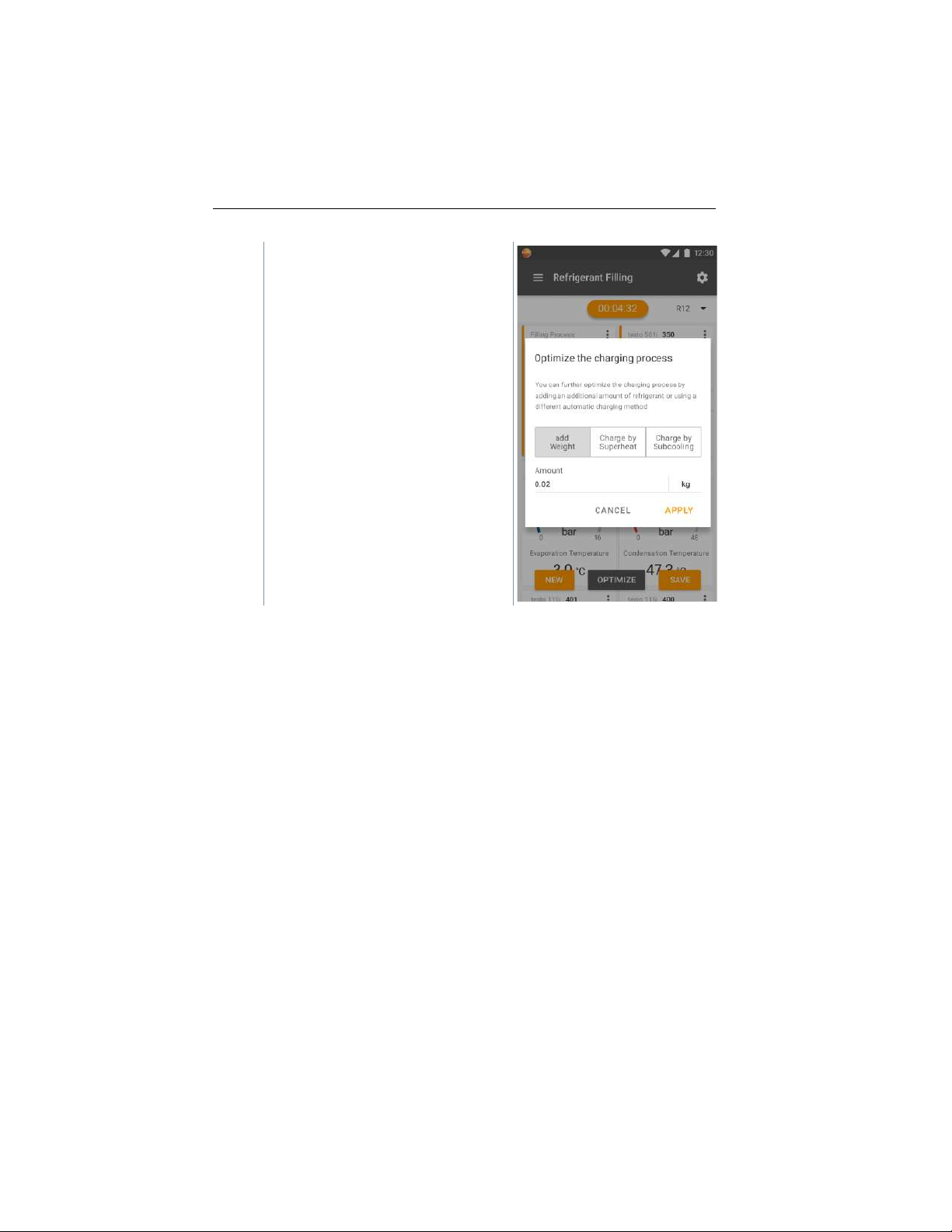
Once charging is finished, the
process can be repeated [NEW] or
another mode for charging
[OPTIMIZE] can be selected.
Find Quality Products Online at: [email protected]
www.GlobalTestSupply.com
Page 24

8 Using the product
22
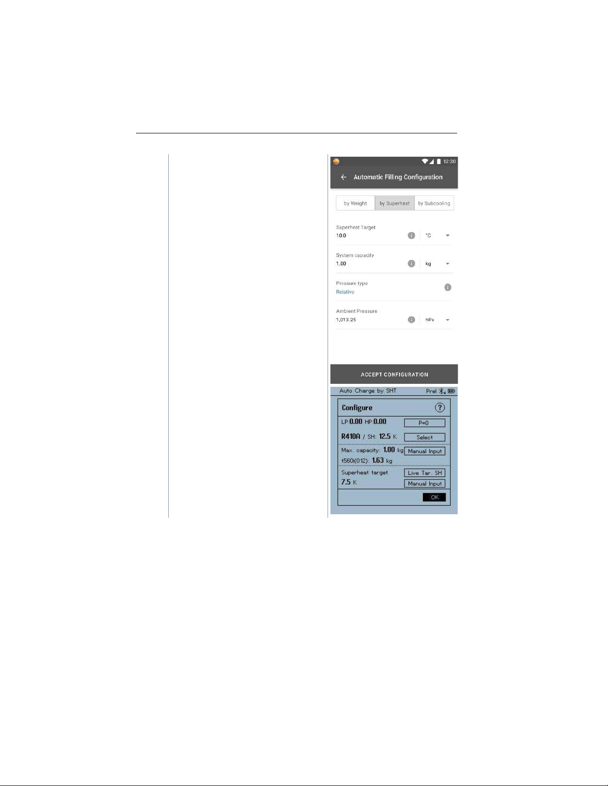
8.5 Automatic charging by superheat
This function enables a refrigerant circuit to be charged via the target superheat
value using the testo 560i scale and the testo Smart Valve in combination with
the app or testo 550s / testo 557s manifold.
For this, the current superheating value is determined. Based on this
information, a target superheat value can be entered. The system is filled
automatically until the target value is reached.
Displaying the target superheat value is only possible in combination
with testo 115i smart probes.
The appropriate maximum charge value for a system must be entered
in the [Max charge] field on the manifold/app.
The appropriate superheat target value for a system must be entered
on the manifold/app.
Based on the specified system size the algorithm creates a maximum
weight to be filled. When this maximum weight is reached, automatic
filling is paused and must be restarted. This prevents overfilling or
incorrect filling.
When using the manifold, the app is in second-screen mode. All
settings must be made on the manifold.
Before each measurement, check that the refrigerant hoses are in
flawless condition.
The system must be supervised by a competent person throughout the
entire process.
✓
testo 560i and testo Smart Valve are connected via Bluetooth to the
testo Smart App or the testo 550s / testo 557s manifold.
✓
testo 560i and testo Smart Valve are integrated into the refrigerant
circuit.
1
Select the required refrigerant on the manifold/app and press
[Menu/Enter] to confirm.
1.1
If necessary, zero sensor on manifold/app [P = 0].
Find Quality Products Online at: [email protected]
www.GlobalTestSupply.com
Page 25
8 Using the product
23
2
In the manifold/app, select the proper
refrigerant and enter the maximum
system charge.
Find Quality Products Online at: [email protected]
www.GlobalTestSupply.com
Page 26
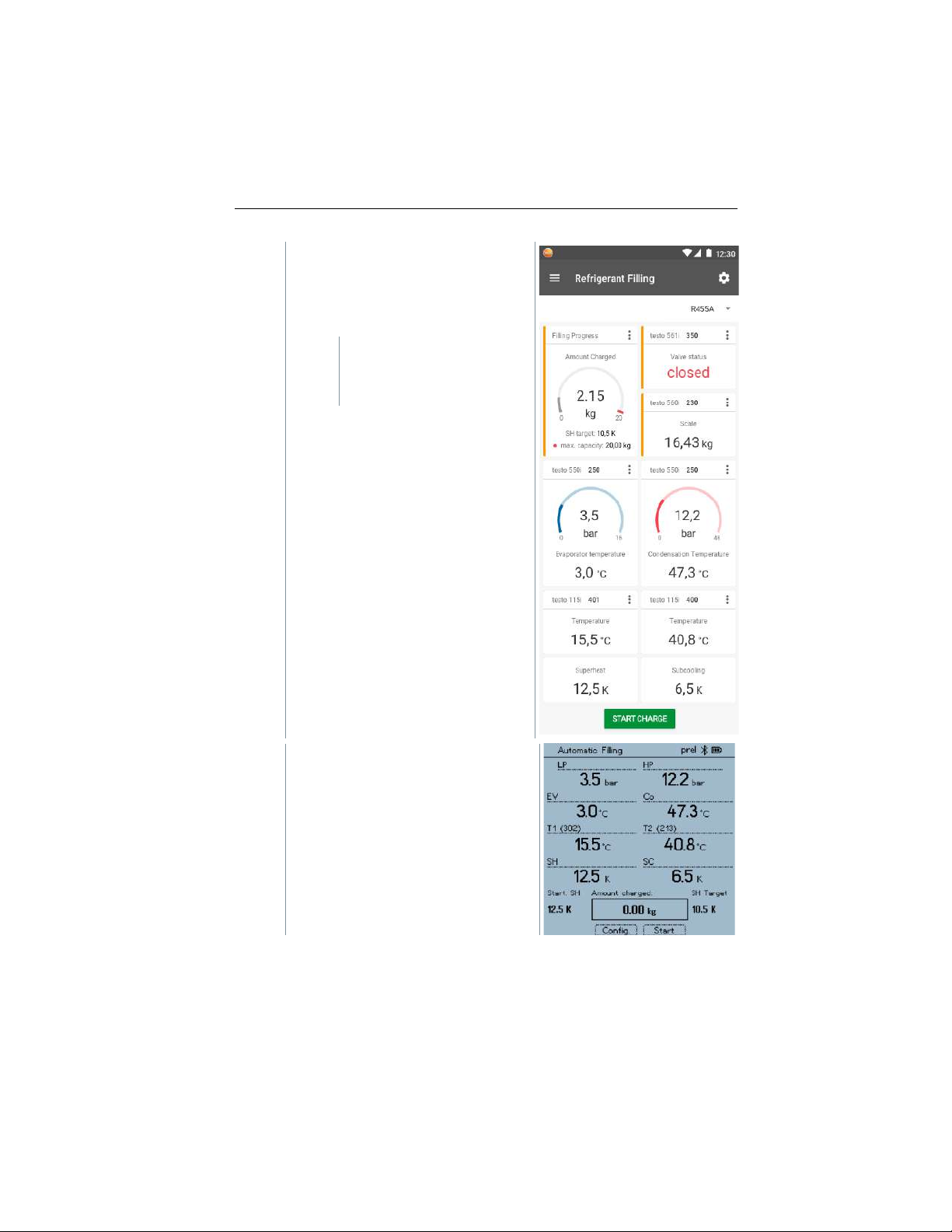
8 Using the product
24
3
Set the required target superheat
value to be reached on the
manifold/app and hit
[START CHARGE] to start the
process.
The valve opens and
attempts to reach the set
superheat by charging
refrigerant.
Added refrigerant is displayed in g/kg
increments on the manifold/app.
Find Quality Products Online at: [email protected]
www.GlobalTestSupply.com
Page 27

8 Using the product
25
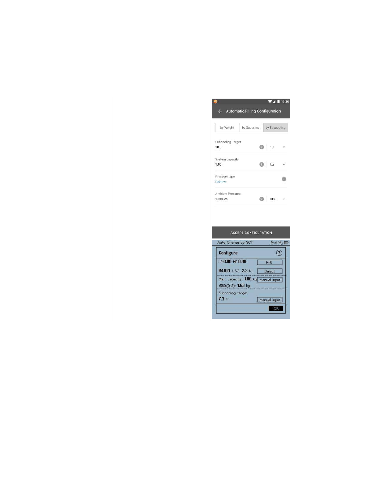
8.6 Automatic charging by subcooling
This function enables a refrigerant circuit to be charged via the target subcooling
value using the testo 560i scale and the testo Smart Valve in combination with
the app or testo 550s / testo 557s manifold.
For this, the current subcooling value is determined. Based on this information,
a target subcooling value can be entered. The system is filled automatically until
the target value is reached.
Displaying the target subcooling value is only possible in combination
with testo 115i smart probes.
The appropriate maximum charge value for a system must be entered
in the [Max charge] field on the manifold/app.
The appropriate subcooling target value for a system must be entered
on the manifold/app.
When using the manifold, the app is in second-screen mode. All
settings must be made on the manifold.
Based on the specified system size the algorithm creates a maximum
weight to be filled. When this maximum weight is reached, automatic
filling is paused and must be restarted. This prevents overfilling or
incorrect filling.
Before each measurement, check that the refrigerant hoses are in
flawless condition.
The system must be supervised by a competent person throughout the
entire process.
✓
testo 560i and testo Smart Valve are connected via Bluetooth to the
testo Smart App or the testo 550s / testo 557s manifold.
✓
testo 560i and testo Smart Valve are integrated into the refrigerant
circuit.
✓
Two testo 115i are attached and connected via Bluetooth to the testo
Smart App or the testo 550s / testo 557s manifold.
1
Select the required refrigerant on the manifold/app and press
[Menu/Enter] to confirm.
1.1
If necessary, zero sensor on manifold/app [P = 0].
Find Quality Products Online at: [email protected]
www.GlobalTestSupply.com
Page 28
8 Using the product
26
2
In the manifold/app, select the proper
refrigerant and enter the maximum
system charge.
Find Quality Products Online at: [email protected]
www.GlobalTestSupply.com
Page 29
8 Using the product
27
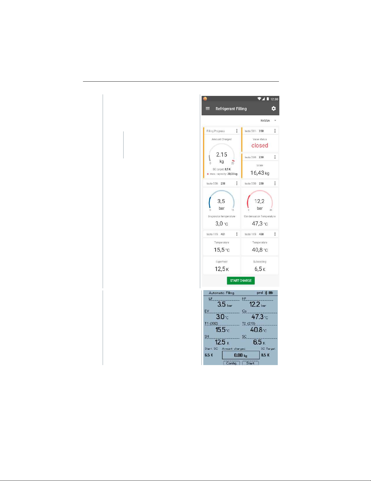
3
Set the required target subcooling
value to be reached on the
manifold/app and hit
[START CHARGE] to start the
process.
The valve opens and
attempts to reach the set
subcooling by charging
refrigerant.
Added refrigerant is displayed in g/kg
increments on the manifold/app.
Find Quality Products Online at: [email protected]
www.GlobalTestSupply.com
Page 30

8 Using the product
28
8.7 Automatic charging via target superheat
This function enables a refrigerant circuit to be charged via the target superheat
using the testo 560i scale and the testo Smart Valve in combination with the
app or the testo 550s / testo 557s manifold.
For this, two testo 605i Smart Probes are connected to the manifold or the testo
Smart App. Based on this information, the optimum target superheat can be
calculated live. The system is filled automatically until the target value is
reached.
Displaying the target superheat value is only possible in combination
with testo 115i smart probes and testo 605i smart probes.
The appropriate maximum charge value for a system must be entered
in the [Max charge] field on the manifold/app.
The appropriate target superheat value for a system must be entered
on the manifold/app.
Based on the specified system size the algorithm creates a maximum
weight to be filled. When this maximum weight is reached, automatic
filling is paused and must be restarted. This prevents overfilling or
incorrect filling.
When using the manifold, the app is in second-screen mode. All
settings must be made on the manifold.
Before each measurement, check that the refrigerant hoses are in
flawless condition and applied to all ports tight to prevent leaks.
The system must be supervised by a competent person throughout the
entire process.
✓
testo 560i and testo Smart Valve are connected via Bluetooth to the
testo Smart App or the testo 550s / testo 557s manifold.
✓
testo 560i and testo Smart Valve are integrated into the refrigerant
circuit.
✓
Two testo 115i and two testo 605i are attached and connected via
Bluetooth to the testo Smart App or the testo 550s / testo 557s
manifold.
Find Quality Products Online at: [email protected]
www.GlobalTestSupply.com
Page 31
8 Using the product
29
1
Select the required refrigerant on the manifold/app and press
[Menu/Enter] to confirm.
1.1
If necessary, zero sensor on manifold/app [P = 0].
2
3
4
5
6
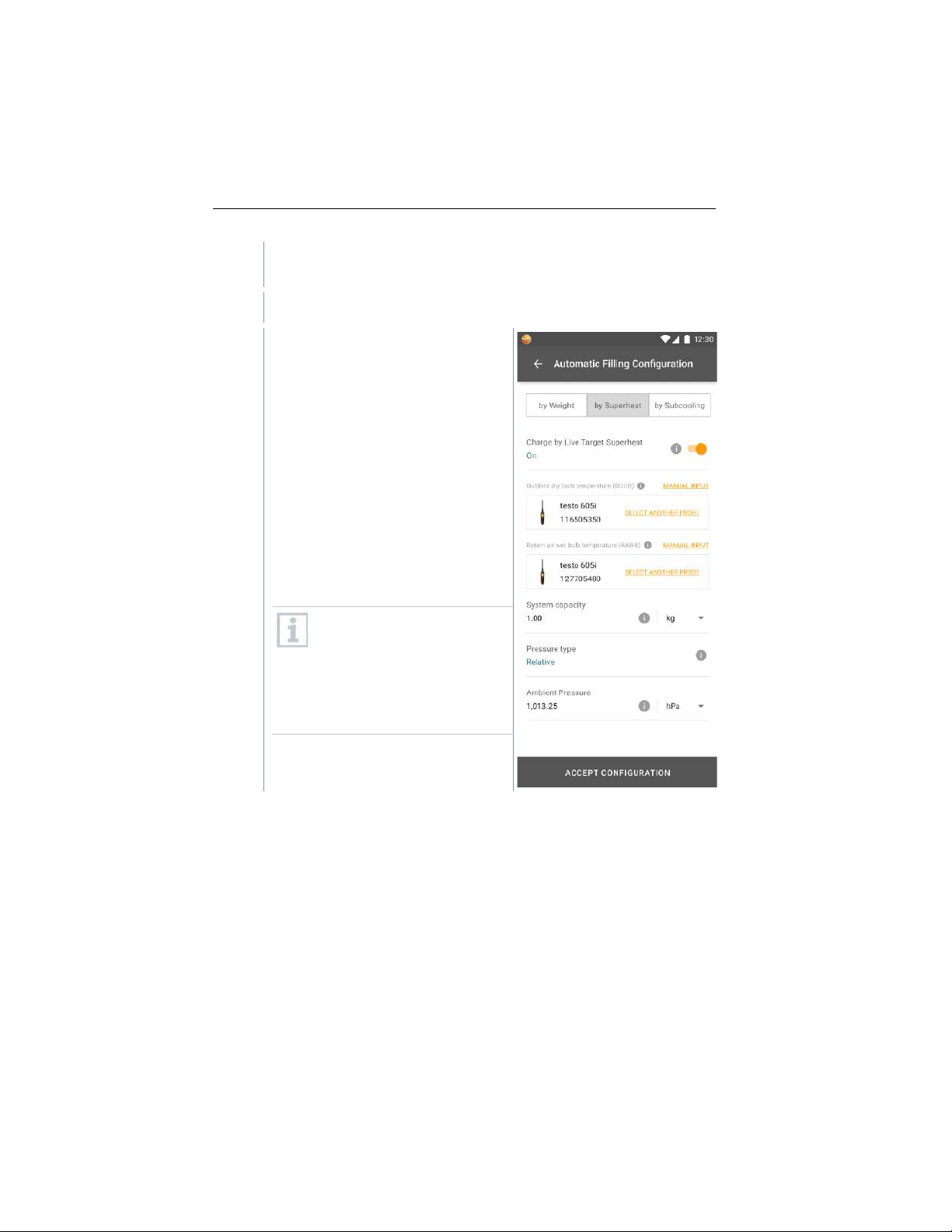
In the manifold/app, enter the
maximum system charge.
Select Live Target Superheat.
Connect two 605i smart probes, one
to outdoor dry bulb and the other to
indoor wet bulb.
Place two 605i smart probes to there
corresponding locations as
configured.
Press [OK] and a target superheat
value will be calculated.
If the target superheat value is
XXX, the method cannot be
used as it is outside the
allowed ambient ranges.
Select manual superheat input
to charge the system by
superheat.
Find Quality Products Online at: [email protected]
www.GlobalTestSupply.com
Page 32
8 Using the product
30
7
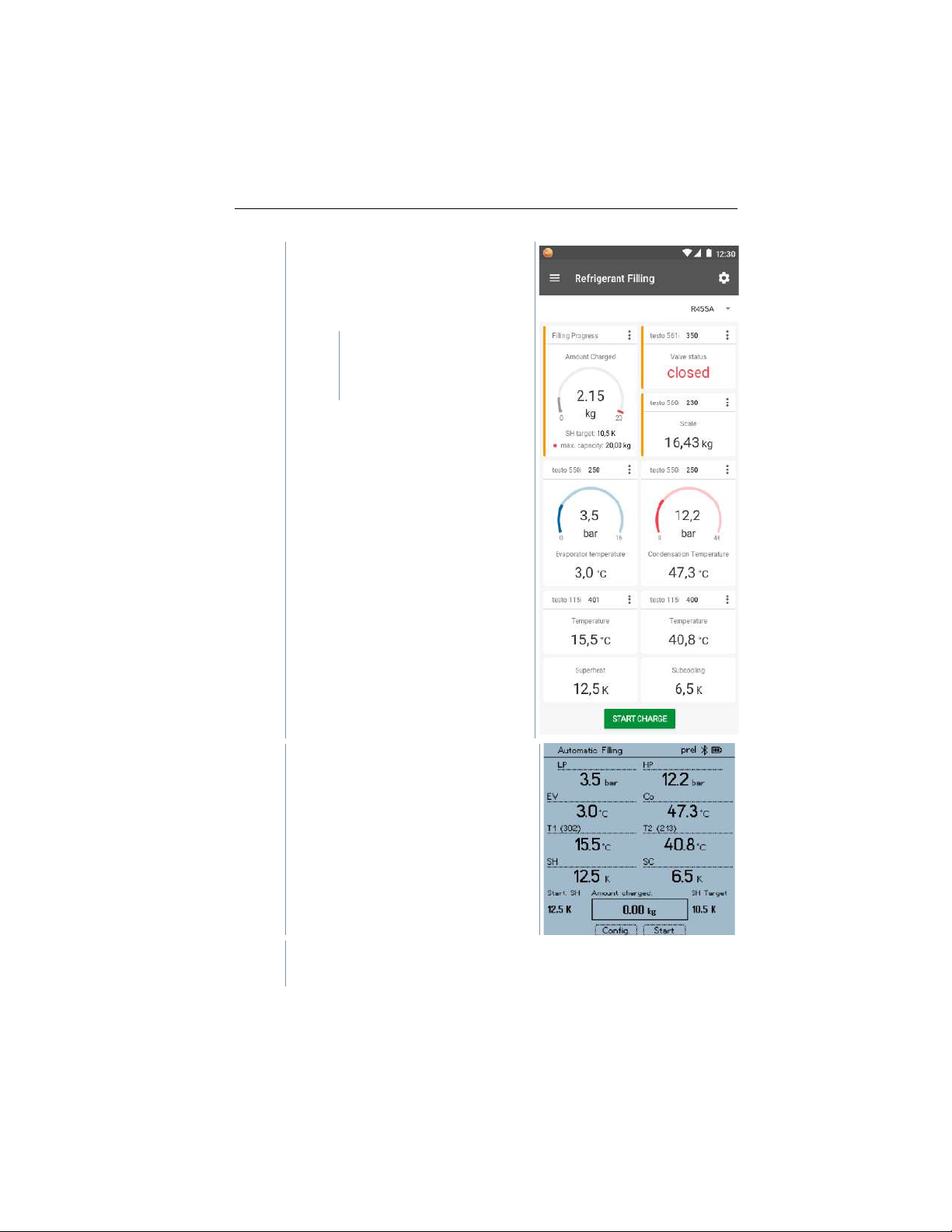
Set the required target superheat
value to be reached on the
manifold/app and hit
[START CHARGE] to start the
process.
Refrigerant is
automatically supplied to
the system until the set
value is reached.
Added refrigerant is displayed in g/kg
increments on the manifold/app.
8
Add another purging section to clear your lines of refrigerant into the
system:
Find Quality Products Online at: [email protected]
www.GlobalTestSupply.com
Page 33

8 Using the product
31
- Turn the bottle valve to the closed position.
- Purge the lines by pressing the valve on off button 3 times until
all refrigerant has been clear of the lines into the system.
Find Quality Products Online at: [email protected]
www.GlobalTestSupply.com
Page 34
8 Using the product
32
8.8 Control via app
✓
Scale and valve are switched on.
✓
The app is installed on the smartphone and connected to the valve
and scale via Bluetooth®.
Settings and controls are implemented via the app.
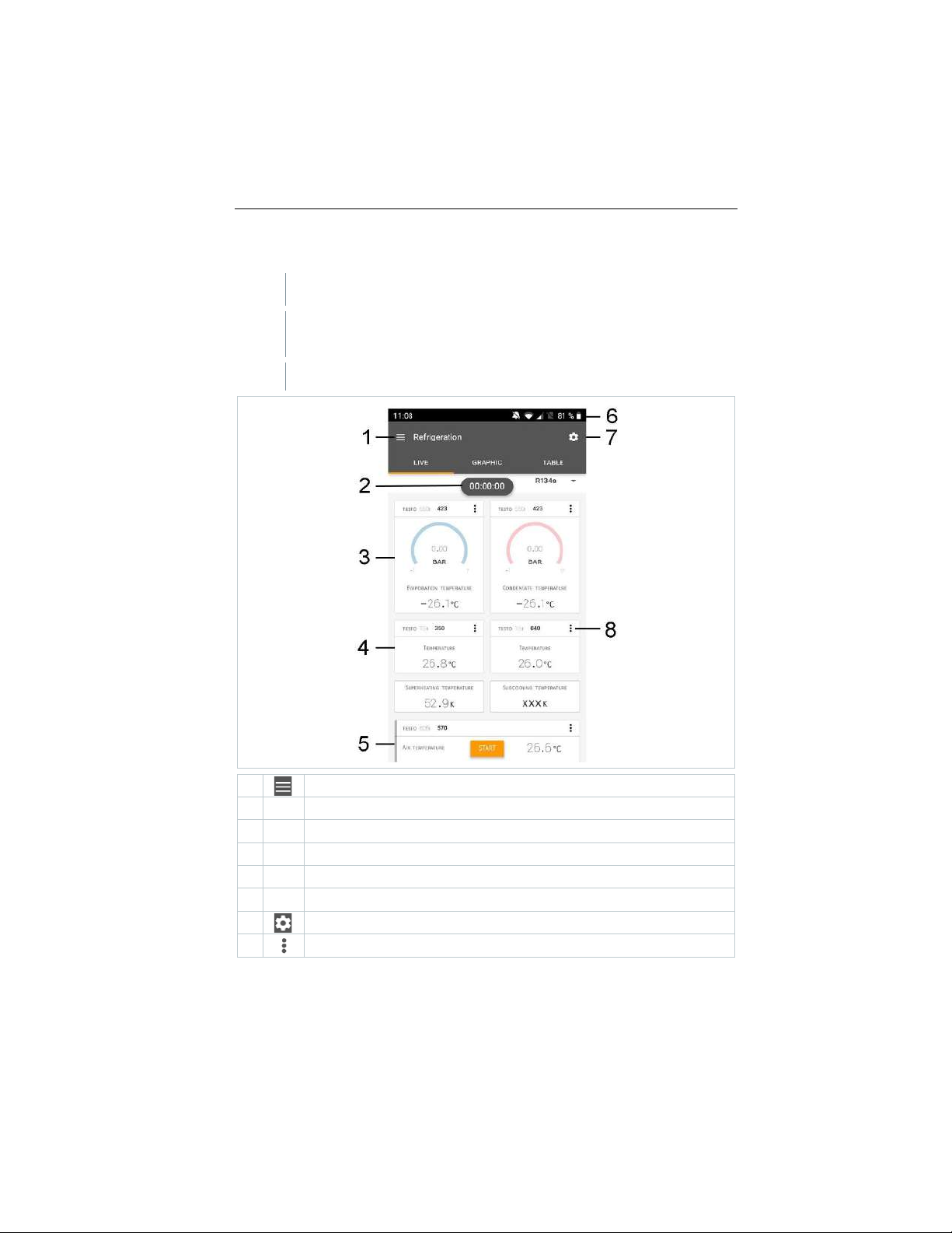
1 Open main menu
2
Display of the measurement period
3 Display of the maximum system charging
4 Reading for each probe
5 Can be controlled with different function keys
6 Instrument status bar
7 Configuration
8 Edit reading display
Find Quality Products Online at: [email protected]
www.GlobalTestSupply.com
Page 35
8 Using the product
33
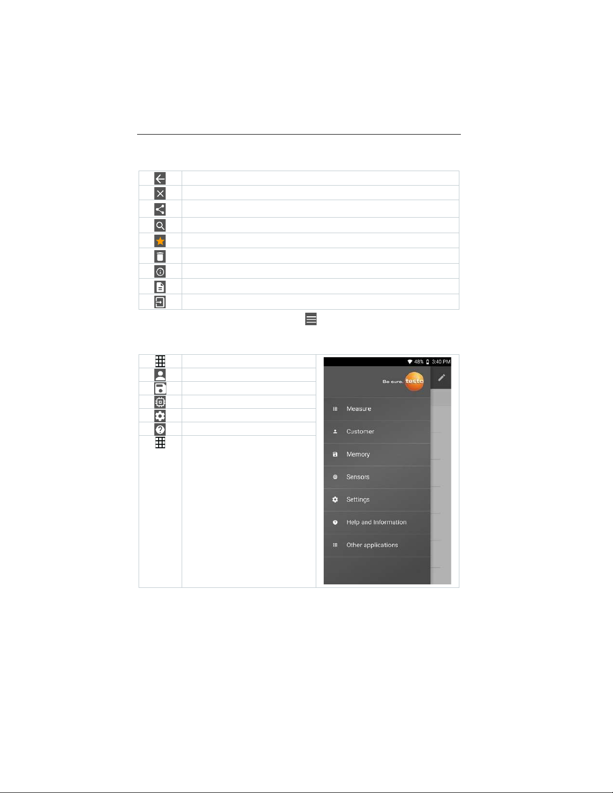
Further symbols on the user interface (without numbering)
One level back
Exit view
Share measurement data/report
Search
Favourite
Deleting
Further information
Display report
Multiple selection
The Main menu can be accessed via the icon at top left. To exit the main
menu, select a menu or right-click on the guided menus. The last screen
displayed is shown.
Measure
Customer
Memory
Sensors
Settings
Help and Information
Other applications
Find Quality Products Online at: [email protected]
www.GlobalTestSupply.com
Page 36
8 Using the product
34
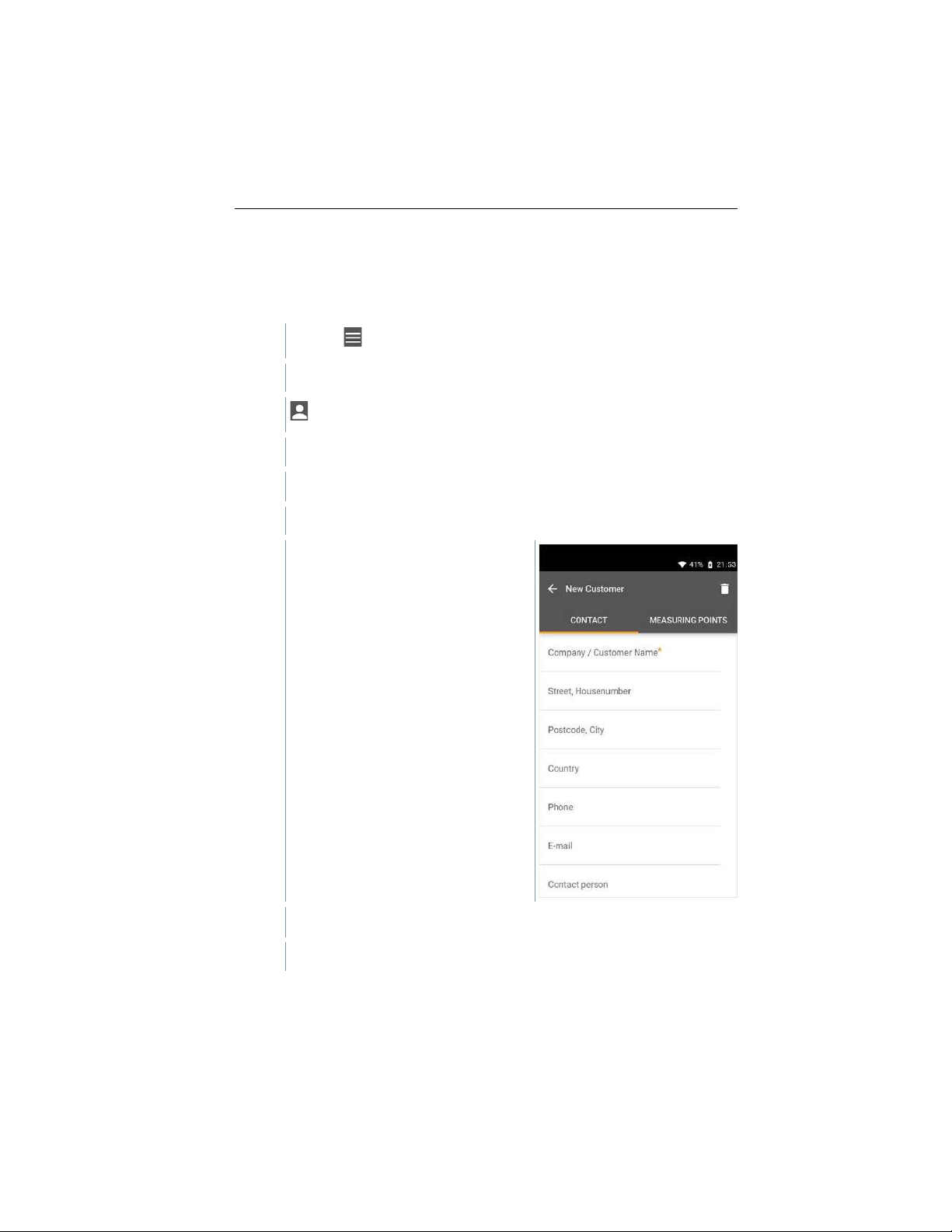
8.8.1 Creating and editing a customer
In the Customer menu, all customer and measuring site information can be
created, edited and deleted. Fields marked with * are mandatory. Without any
information in this field, no customers or measuring sites can be stored.
1
Click on .
Main menu opens.
2
Click on Customer.
The Customer menu opens.
3
Click on + New Customer.
A new customer can be created.
4
Store all relevant customer data.
5
Click on Save.
The new customer was saved.
Find Quality Products Online at: [email protected]
www.GlobalTestSupply.com
Page 37
8 Using the product
35
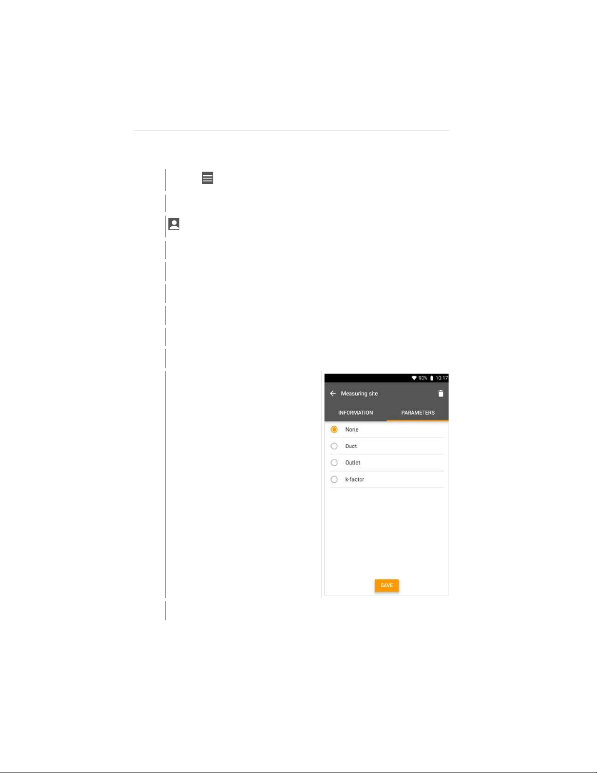
8.8.2 Creating and editing measuring sites
1
Click on .
Main menu opens.
2
Click on Customer.
The Customer menu opens.
3
Click on + New Customer.
4
Click on right tab Measuring Points.
5
Click on + New Measuring Point.
A new measuring point can be created.
6
Store all relevant measuring site information.
7
Click on right tab Parameters.
8
Select further parameters.
Find Quality Products Online at: [email protected]
www.GlobalTestSupply.com
Page 38
8 Using the product
36
For the duct, outlet or duct with k-factor measuring points, further
parameter settings can be implemented.
9
Click on Save.
The new measuring site has been saved.
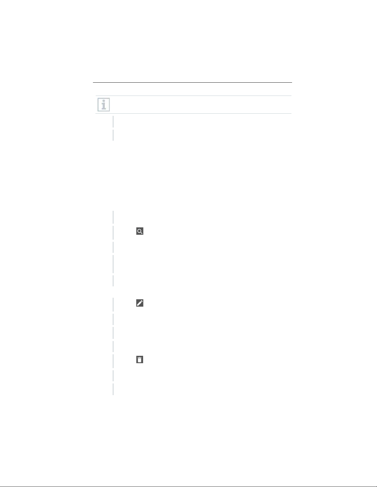
8.8.3 Searching for and deleting measurement results
In the Memory menu, you can call up all the stored measurements, analyze
them in detail and also create and save csv data and PDF reports. When
clicking on a measurement, an overview of the measurement results is
displayed.
In the Memory menu, all stored measurements are sorted by date and time.
Searching
✓
The Memory menu is open.
1
Click on .
Search field with measurements opens.
2
Enter the customer name or measuring site or date/time in the search
field.
The result is displayed.
Deleting
1
Click on .
A check box is displayed in front of each measurement.
2
Click on the required measurement.
A tick is displayed in the respective box.
3
Click on .
Information window is displayed.
4
Acknowledge the information.
Find Quality Products Online at: [email protected]
www.GlobalTestSupply.com
Page 39
8 Using the product
37
Selected measurements were deleted.
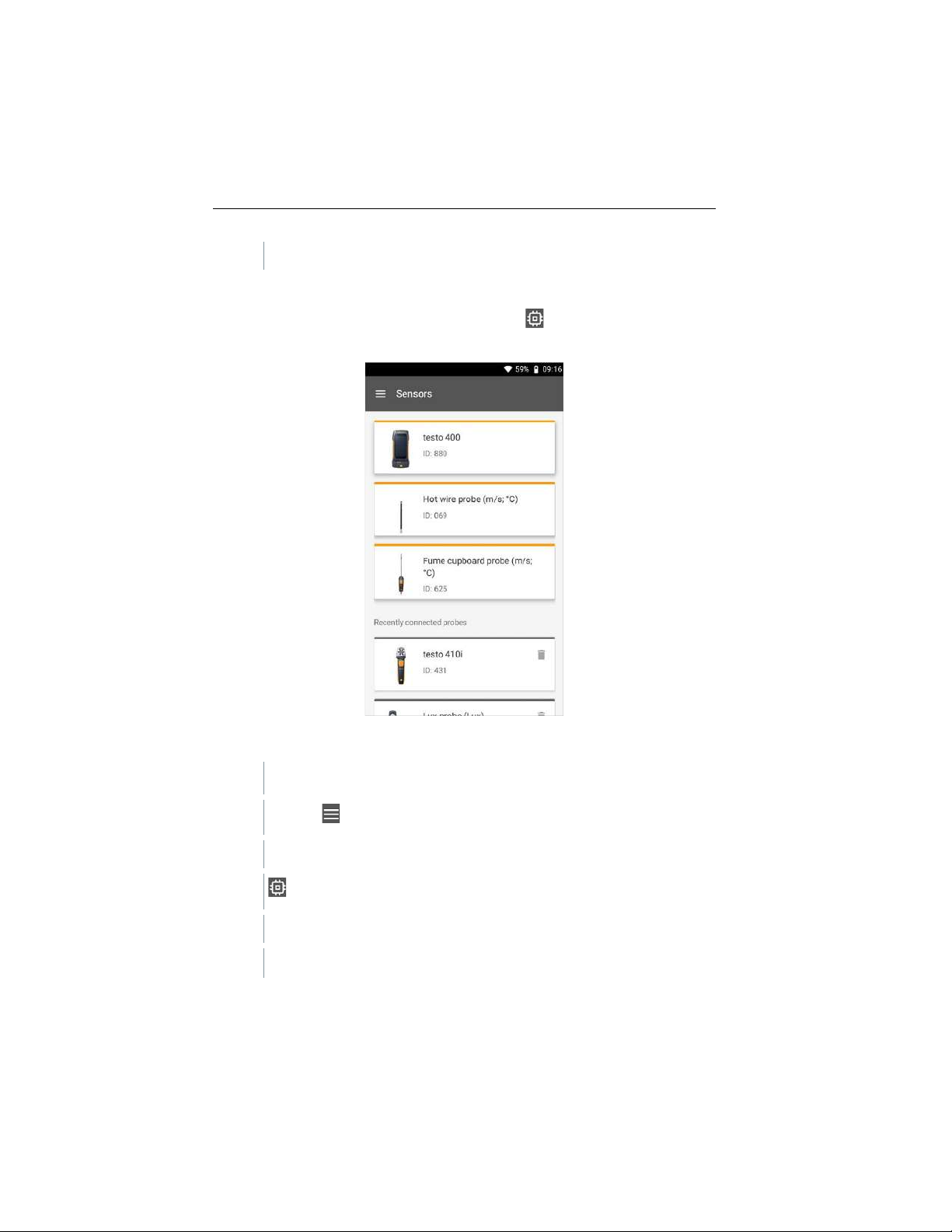
8.8.4 Sensors
All sensors used with the App can be found in the Sensors menu. There,
you can view general information about currently connected probes as well as
recently connected probes.
8.8.4.1 Information
Information is stored for each probe.
✓
The app is connected to testo 550s / testo 557s.
1
Click on .
Main menu opens.
2
Click on Sensors.
The Sensors menu opens.
3
Click on one of the displayed probes.
Find Quality Products Online at: [email protected]
www.GlobalTestSupply.com
Page 40
8 Using the product
38
Information is displayed about the model, order number, serial number
and firmware version.
8.8.4.2 Settings
Settings can also be made for each probe.
✓
The probe is connected to the App.
1
Click on .
Main menu opens.
2
Click on Sensors.
The Sensors menu opens.
3
Click on one of the displayed probes.
4
Click on the Settings tab.
5
Click on one of the displayed probes.
Settings appear that can be changed if necessary.
8.8.5 Language
1
Click on Settings.
The Settings menu opens.
2
Click on Language.
A window with different languages opens.
3
Click on the required language.
The required language is set.
8.8.6 Measurement settings
1
Click on Settings.
Find Quality Products Online at: [email protected]
www.GlobalTestSupply.com
Page 41
8 Using the product
39
The Settings menu opens.
2
Click on Measurement settings.
A window with different basic settings for measurement opens.
3
Click on the required settings and change if necessary.
The required measurement settings are set.
4
Exit Measurement settings.
8.8.7 Company details
1
Click on Settings.
The Settings menu opens.
2
Click on Company details.
A window with company details opens.
3
Click on the required data and enter if necessary.
The required company details are set.
4
Exit Company details.
8.8.8 Privacy settings
1
Click on Settings.
The Settings menu opens.
2
Click on Privacy settings.
A window with privacy settings opens.
3
Activate or deactivate the required settings.
The required settings are set.
Find Quality Products Online at: [email protected]
www.GlobalTestSupply.com
Page 42

8 Using the product
40
4
Exit Privacy settings.
8.8.9 Help and Information
Under Help and Information, you will find information about the testo 550s /
testo 557s, and the tutorial can be called up and implemented. This also where
legal information can be found.
8.8.9.1 Instrument information
1
Click on Help and Information.
The Help and Information menu opens.
2
Click on Instrument information.
The current App version, Google Analytics instance ID, refrigerant
version and update are displayed for the connected instrument.
Automatic updates for instruments can be enabled or disabled.
>
Use the slider to activate or deactivate Update for connected
instruments.
8.8.9.2 Tutorial
1
Click on Help and Information.
The Help and Information menu opens.
2
Click on Tutorial.
The tutorial shows you the most important steps prior to
commissioning.
8.8.9.3 Exclusion of liability
1
Click on Help and Information.
The Help and Information menu opens.
2
Click on Exclusion of liability.
The data protection information and licence usage information is
displayed.
Find Quality Products Online at: [email protected]
www.GlobalTestSupply.com
Page 43

9 Maintenance
41
9 Maintenance
9.1 Calibration
The testo 560i scale and the testo Smart Valve are supplied with a
factory calibration certificate as standard.
Recalibration once every 12 months is recommended in many
applications.
This can be carried out by Testo Industrial Services (TIS) or other
certified service providers.
Please contact testo for further information.
9.2 Cleaning instruments
Do not use any aggressive cleaning agents or solvents! Mild household
cleaning agents and soap suds may be used.
>
If the instrument housing is dirty, clean it with a damp cloth.
Connect high pressure air and use the function to click 3 times the
button and the valve will open for 1 s. This can help to remove small
dust inside the valve.
9.3 Keeping connections clean
>
Keep screw connections clean and free of grease and other deposits;
clean with a damp cloth as required.
9.4 Removing oil residues
>
Carefully blow out oil residues in the valve block using compressed
air.
9.5 Ensuring measuring accuracy
Testo Customer Service will be happy to help you as required.
>
Check the instrument regularly for leaks. Keep to the permissible
pressure range!
>
Calibrate the instrument regularly (recommendation: once a year).
Find Quality Products Online at: [email protected]
www.GlobalTestSupply.com
Page 44

9 Maintenance
42
9.6 Changing batteries
Changing batteries in the testo 560i scale
✓
The instrument is switched off.
1
Open battery compartment.
2
Remove spent batteries and insert new ones (4 x 1.5V, type AA /
Mignon / LR6) into the battery compartment. Observe the polarity!
3
Close the battery compartment.
After inserting the batteries, the instrument switches on automatically
and is in Bluetooth® connection mode.
In Bluetooth® connection mode, connection can be established to the
testo Smart App or to a testo 550s or testo 557s manifold.
Do not change or remove batteries during operation, otherwise the
charging process will be interrupted.
When not in use for a long period: Take out the batteries.
Changing the batteries in the testo Smart Valve
✓
The instrument is switched off.
1
Unfold the suspension hook and open the battery compartment (clip
lock).
2
Remove the spent battery and insert a new one (1 x 9.0V (6LR61)
block battery) into the battery compartment. Observe the polarity!
3
Close the battery compartment.
After inserting the batteries, the instrument switches on automatically
and is in Bluetooth® connection mode.
In Bluetooth® connection mode, connection can be established to the
testo Smart App or to a testo 550s or testo 557s manifold.
Do not change or remove batteries during operation, otherwise the
charging process will be interrupted.
Find Quality Products Online at: [email protected]
www.GlobalTestSupply.com
Page 45

10 Technical data
43
When not in use for a long period: Take out the batteries.
10 Technical data
10.1 Technical data for testo 560i
Feature
Value
Connection to the sensor
BLE 4.2+
Interface
BLE 4.2+
Power supply
Power source: Batteries 4 x 1.5 V type AA /
Mignon / LR6
Battery life: > 70 h at 25 °C
IP class
44
Weight
4.01 kg (with batteries, with bag)
3.11 kg (with batteries, without bag)
Dimensions
Approx. 310 x 287 x 58 mm
Ambient conditions
Operating temperature: -10 to 50 °C / 14 to
122 °F
Storage temperature: -10 to 50 °C / 14 to
122 °F
Humidity in area of use: 10…90 % RH
Measuring range
0.00 to 100.00 kg
Accuracy (nominal
temperature 22 °C/71.6 °F)
(After zeroing)
Operating temperature 25 ± 5 °C (inclination
angle around 0°):
≤ ± (10 g + 0.03 %rdg) (0~30 kg)
≤ ± (10 g + 0.05 %rdg) (30~100 kg)
Other operating temperature (inclination angle
around 0°):
≤ ± (20 g) (0~10 kg)
≤ ± (10 g + 0.15 %rdg) (10~100 kg)
Solution
0.01 kg
Bluetooth range
≥ 30 m in all directions in an open area
Find Quality Products Online at: [email protected]
www.GlobalTestSupply.com
Page 46

11 Tips and assistance
44
10.2 Technical data for testo Smart Valve
Feature
Value
Connection to the sensor
BLE 4.2+
Interface
BLE 4.2+
Power supply
Power source: Battery 9.0 V, type 6LR61
Battery life:
> 60 h at 3000 valve actuations
IP class
54
Weight
0.57kg (with battery)
Dimensions
Approx. 95 x 119 x 47 mm
Ambient conditions
Operating temperature: -10 to 50 °C / 14 to
122 °F
Storage temperature: -10 to 50 °C / 14 to
122 °F
Humidity in area of use: 10…90 % RH
Bluetooth range
≥ 50 m in all directions in an open area
Max. permitted operating
pressure
35 bar
11 Tips and assistance
11.1 Accessories
Description
Order no.
Magnetic strap for valve
0564 1001
For a complete list of all accessories and spare parts, please refer to the product
catalogues and brochures or visit our website
12 Support
You can find up-to-date information on products, downloads and links to contact
addresses for support queries on the Testo website at:
If you have any questions please contact your local dealer or the Testo
Customer Service. You can find contact details on the back of this document or
online at
Find Quality Products Online at: [email protected]
www.GlobalTestSupply.com
Page 47

Page 48

0970 5610 en 02 – 06.2022
Find Quality Products Online at: [email protected]
www.GlobalTestSupply.com
 Loading...