

Page 1

testo 550s / testo 557s digital manifold
Instruction manual
Find Quality Products Online at: [email protected]
www.GlobalTestSupply.com
Page 2

Contents
1
2
3
4
5
6
7
8
Contents
About this document ........................................................................... 7
Safety and disposal .............................................................................. 7
Product-specific approvals ................................................................. 7
Product-specific information............................................................... 8
Use ......................................................................................................... 8
Product description ............................................................................. 9
6.1 Overview of the testo 550s ................................................................................. 9
6.2 Overview of the testo 557s ............................................................................... 10
6.3 Overview of main menu .................................................................................... 11
6.4 Control keys ..................................................................................................... 12
First steps ........................................................................................... 12
7.1 Inserting (rechargeable) batteries ..................................................................... 12
7.2 Switching the instrument on and off .................................................................. 13
7.3 Setup wizard ..................................................................................................... 13
Using the product ............................................................................... 14
8.1 Preparing for measurement .............................................................................. 14
8.1.1 Operating the valve positioners ................................................................................ 14
8.1.2 Automatic mode ....................................................................................................... 15
8.2 Measuring mode ............................................................................................... 15
8.2.1 Refrigeration ............................................................................................................ 15
8.2.2 Evacuation ............................................................................................................... 19
8.2.3 Pressure Leak Test .................................................................................................. 22
8.2.4 Target Superheat ..................................................................................................... 25
8.2.5 Compressor Test (DLT) ............................................................................................ 29
8.2.6 Delta T ..................................................................................................................... 32
8.3 Bluetooth .......................................................................................................... 33
8.3.1 Probes compatible with the instrument ..................................................................... 33
8.3.2 Establishing a connection ......................................................................................... 34
8.3.3 Switching on/off ........................................................................................................ 35
8.3.3.1 Switching on ............................................................................................................................35
8.3.3.2 Switching off ............................................................................................................................36
8.3.3.3 Manual probe selection ...........................................................................................................36
8.4 Settings ............................................................................................................ 37
Find Quality Products Online at: [email protected]
www.GlobalTestSupply.com
Page 3

Contents
9
8.4.1 Duration .................................................................................................................. 38
8.4.2 Brightness ............................................................................................................... 38
8.4.3 Auto Off ................................................................................................................... 39
8.4.4 Auto Tfac (Temperature compensation factor) ......................................................... 40
8.4.5 Units ........................................................................................................................ 41
8.4.6 Language ................................................................................................................ 42
8.4.7 Setup Wizard ........................................................................................................... 43
8.4.8 Factory Settings ...................................................................................................... 44
8.4.9 Instrument ............................................................................................................... 45
Smart App........................................................................................... 46
9.1 App – user interface ......................................................................................... 46
9.2 Main menu ....................................................................................................... 47
9.3 Measurement menu .......................................................................................... 48
9.3.1 Basic view ............................................................................................................... 49
9.3.1.1 Graphic view ........................................................................................................................... 49
9.3.1.2 Table view ............................................................................................................................... 50
9.3.2 Refrigeration ............................................................................................................ 50
9.3.3 Target Superheat ..................................................................................................... 53
9.3.4 Pressure Leak Test ................................................................................................. 55
9.3.5 Evacuation .............................................................................................................. 57
9.4 Customer .......................................................................................................... 58
9.4.1 Creating and editing a customer .............................................................................. 58
9.4.2 Creating and editing measuring sites ....................................................................... 59
9.5 Memory ............................................................................................................ 61
9.5.1 Searching for and deleting measurement results ...................................................... 61
9.6 Sensors ............................................................................................................ 62
9.6.1 Information .............................................................................................................. 62
9.6.2 Settings ................................................................................................................... 63
9.7 Settings ............................................................................................................ 63
9.7.1 Language ................................................................................................................ 63
9.7.2 Measurement settings ............................................................................................. 64
9.7.3 Company details ...................................................................................................... 64
9.7.4 Privacy settings ....................................................................................................... 64
9.8 Help and Information ........................................................................................ 65
9.8.1 Instrument information ............................................................................................. 65
9.8.2 Tutorial .................................................................................................................... 65
9.8.3 Exclusion of liability ................................................................................................. 66
Find Quality Products Online at: [email protected]
www.GlobalTestSupply.com
Page 4

10
11
12
13
Contents
9.9 testo DataControl archiving software ................................................................ 66
9.9.1 System requirements ............................................................................................... 66
9.9.1.1 Operating system ....................................................................................................................66
9.9.1.2 PC ............................................................................................................................................66
9.9.2 Procedure ................................................................................................................ 67
Maintenance........................................................................................ 68
10.1 Calibration ........................................................................................................ 68
10.2 Cleaning the instrument .................................................................................... 68
10.3 Keeping connections clean ............................................................................... 69
10.4 Removing oil residues ...................................................................................... 69
10.5 Ensuring measuring accuracy ........................................................................... 69
10.6 Changing batteries/rechargeable batteries ........................................................ 69
Technical data .................................................................................... 70
Tips and assistance ........................................................................... 73
12.1 Questions and answers .................................................................................... 73
12.2 Error Codes ...................................................................................................... 73
12.2.1 Main screen ............................................................................................................. 73
12.2.2 Status view .............................................................................................................. 73
12.3 Accessories and spare parts ............................................................................. 74
Support ............................................................................................... 74
Find Quality Products Online at: [email protected]
www.GlobalTestSupply.com
Page 5
1
Note: basic or further information
Warning
Warning!
Caution!
occur.
> Take the specified precautionary measures.
1
…
Action: several steps, the sequence must be followed
-
Result of an action
Requirement
>
Action
Menu
Elements of the instrument, the instrument display or the
program interface.
[OK]
Control keys of the instrument or buttons of the program
interface.
2
3
1 About this document
About this document
• The instruction manual is an integral part of the instrument.
• Pay close attention to the safety instructions and warning advice in order to
prevent injury and damage to the product.
• Please read this instruction manual carefully and familiarize yourself with the
product before putting it to use.
• Familiarity with a PC as well as the Microsoft® products is assumed in this
documentation.
Symbols and writing standards
Display Explanation
advice, risk level according to the signal word:
Serious physical injury may occur.
Minor physical injury or damage to the equipment may
2
Safety and disposal
Please observe the Testo information document (enclosed with the product).
Product-specific approvals
Please find the current country approvals in the Approvals and Certifications
document.
7
Find Quality Products Online at: [email protected]
www.GlobalTestSupply.com
Page 6

4
5
4 Product-specific information
Product-specific information
• The measuring instrument being dropped or any other comparable
mechanical stress may cause breakage of the pipe pieces in the refrigerant
hoses. The valve positioners may also suffer damage, causing further
damage inside the measuring instrument that is not necessarily visible
externally. Therefore, always replace the refrigerant hoses with new ones
after the measuring instrument is dropped or after any comparable
mechanical stress. For your own safety, you should return the measuring
instrument to the Testo Customer Service for technical inspection.
• Electrostatic charging may destroy the instrument. Integrate all the
components (system, manifold's valve block, refrigerant bottle, etc.) into the
potential bonding (earthing). Please see the safety instructions for the
system and the refrigerant used.
• Refrigerant gases can harm the environment. Please note the applicable
environmental regulations.
• Use with A2L refrigerants
Testo measuring instruments (as of July 2020) can be used in compliance
with the prescribed laws, standards, directives and safety regulations for
refrigeration systems and refrigerants as well as regulations of the
manufacturers of refrigerants of safety group A2L as per ISO 817.
Regional standardization and interpretation must always be observed.
For example, DIN EN 378-Part 1-4 applies to the scope of the EN
standards.
During maintenance work, the employer must ensure that a hazardous
explosive atmosphere is prevented (see also: TRBS1112, TRBS2152
VDMA 24020-3).
A hazardous and potentially explosive atmosphere must be anticipated
during maintenance and repair work on refrigeration systems with
flammable refrigerants (e.g. those of category A2L and A3).
Maintenance, repairs, removal of refrigerants and commissioning of
systems may only be carried out by qualified personnel.
Use
testo 550s and testo 557s are digital manifolds for maintenance and service
work refrigeration systems, heat pumps, and other air conditioning systems.
They may only be used by qualified authorized personnel.
The functions of the instruments testo 550s and testo 557s mean they can
replace mechanical manifolds, thermometers and pressure/temperature charts.
Pressures and temperatures can be applied, adapted, tested and monitored.
The instruments testo 550s and testo 557s are compatible with most non-
Find Quality Products Online at: [email protected]
corrosive refrigerants, water and glycol. The instruments testo 550s and testo
557s are not compatible with refrigerants containing ammonia.
The products must not be used in potentially explosive atmospheres!
8
www.GlobalTestSupply.com
Page 7

6
6.1
Mini-DIN probe socket for NTC
cover
•
•
5
6
3 x hose bracket for refrigerant
hoses
3 x connections 7/16" UNF, brass
positioner.
Product description
Overview of the testo 550s
6 Product description
temperature probe, with socket
1
3 Display. Instrument status icons 4
Control keys
7 2 x valve positioner 8
Left/right: Low/high pressure for
refrigerant hoses with quick
release screw fitting; passage
can be closed via valve
9
positioner center: e.g. for
refrigerant bottles, with sealing
cap, refrigerant hoses with quickrelease screw fitting; passage
can be closed via valve
Foldable suspension device
2
(rear).
Rear
Battery compartment
Mini USB port for firmware
update
It is not possible to charge
rechargeable batteries in the
instrument.
Sight glass for refrigerant flow
9
Find Quality Products Online at: [email protected]
www.GlobalTestSupply.com
Page 8

6.2
Mini-DIN probe socket for NTC
cover
Rear
•
•
5
Control keys
6
Sight glass for refrigerant flow
4 x hose bracket for refrigerant
hoses
Connection 7/16" UNF, brass.
valve positioner.
Connection 7/16" UNF, brass.
valve positioner.
6 Product description
Overview of the testo 557s
1
temperature probe, with socket
3 Display. Instrument status icons 4
7 4 x valve positioner 8
High pressure, for refrigerant
9
hoses with quick-release screw
fitting, passage can be closed via
Connection 7/16" UNF, brass,
11
e.g. for refrigerant cylinders, with
sealing cap
Foldable suspension device
2
(rear).
Battery compartment
Mini USB port for firmware
update
It is not possible to charge
rechargeable batteries in the
instrument.
Connection 5/8" UNF, brass, for
10
vacuum pump
Low pressure, for refrigerant
12
hoses with quick-release screw
fitting, passage can be closed via
10
Find Quality Products Online at: [email protected]
www.GlobalTestSupply.com
Page 9

6.3
Refrigeration
Delta T
Bluetooth®
Connection to the testo Smart App or Smart Probes
Settings
Duration
Information
Overview of main menu
Evacuation
Measuring mode
Pressure Leak Test
Target Superheat
Compressor Test (DLT)
Brightness
Auto Off
Auto Tfac (Temperature compensation factor)
Units
Language
Setup Wizard
Factory Settings
6 Product description
11
Find Quality Products Online at: [email protected]
www.GlobalTestSupply.com
Page 10

6.4
• Open menu
•
•
•
• Switches to the measurement view
•
• Switch off the instrument: Press and
7
7.1
1
Unfold the suspension hook and open the battery compartment (clip
lock).
2
Insert the batteries (scope of delivery) or rechargeable batteries (4 x
the polarity!
3
Close the battery compartment.
After insertion of the batteries, the instrument switches on
automatically and goes into the settings menu.
7 First steps
Control keys
Symbol Meaning
Confirm input
Switch on the display illumination:
Press and hold the key for >2s
Switch off the display illumination:
Press and hold the key for >2s
/
Change/navigate the display screen.
Back to the menu
hold the key for >2s
First steps
Inserting (rechargeable) batteries
1.5V, type AA / Mignon / LR6) into the battery compartment. Observe
When not in use for a long period: Take out the (rechargeable)
batteries.
12
Find Quality Products Online at: [email protected]
www.GlobalTestSupply.com
Page 11
7.2
off
Instrument
Instrument is switched off.
The instrument setup that is implemented can be adapted at any time
7.3
The instrument setup that is implemented can be adapted at any time
Instrument is switched on and the initialization phase has been
completed.
1
Select language: Press [▲] / [▼]
Switching the instrument on and off
7 First steps
Current
Action Function
status
Instrument
Press
Instrument is switched on.
When the measuring instrument is started for the first time, the setup
wizard guides you through the following setting parameters step by
step:
- Language
- testo Smart App
Press and hold
down (> 2 s)
in the Settings menu.
on
Setup wizard
When the testo 550s / testo 557s is started up for the first time and after the
factory settings have been reset, the setup wizard is activated and guides you
step-by-step through the following setup parameters.
in the Settings menu.
Language selection and QR code
and [Menu/Enter] to confirm.
Selecting the language activates
the appropriate presetting of the
units of measurement
13
Find Quality Products Online at: [email protected]
www.GlobalTestSupply.com
Page 12

2
Take a photo of the QR code with a
-
The measurement menu is displayed.
8
8.1
8.1.1
-
-
Close the valve: Turn valve positioner clockwise.
•
•
•
8 Using the product
mobile device of the testo Smart App
and press [Menu/Enter] to confirm.
Using the product
Preparing for measurement
Operating the valve positioners
With respect to the refrigerant flow path, the digital manifold behaves just like a
conventional four-way manifold: The passages are opened by opening the
valves. The applied pressure is measured with the valves closed and the valves
opened.
Open the valve: Turn valve positioner counterclockwise.
WARNING
Valve positioner tightened too tightly.
Damage to the PTFE seal (1).
Mechanical deformation of the valve
piston (2) leading to the PTFE seal (1)
falling out.
Damage to the thread of the threaded
spindle (3) and the valve screw (4).
Broken valve knob (5).
Only tighten the valve positioner hand-tight.
Do not use any tools to tighten the valve
positioners.
14
Find Quality Products Online at: [email protected]
www.GlobalTestSupply.com
Page 13

8.1.2
8.2
Risk of injury caused by refrigerant that is under high pressure, hot, cold,
or toxic!
>
>
>
>
psi).
8.2.1
Automatic mode
The manifold automatically detects the pressure difference between the lowpressure and high-pressure sides. If the measured pressure on the low pressure
side is 14.7 psi higher than on the high pressure side, a dialogue appears and
the display can be changed accordingly. If “yes” is selected, the low pressure
moves from left to right and the high pressure moves from right to left.
This mode is particularly suitable for air conditioning systems that provide
cooling and heating.
Measuring mode
WARNING
Wear protective goggles and safety gloves.
Before applying pressure to the measuring instrument: Always fasten the
measuring instrument on the suspension hook to prevent it from falling
(danger of breakage).
Before each measurement, check the refrigerant hoses are intact and
connected properly. Ensure seals are clean and intact. Do not use any tools
to connect the hoses; only tighten hoses hand-tight (max. torque
5.0 Nm/3.7 ft*lb).
Comply with the permissible measuring range (-1 to 60 bar/-14,7 to 870
Pay attention to this in systems with R744 refrigerant, since these are
frequently operated at higher pressures!
Refrigeration
The Refrigeration application is used to determine the following system
measuring values:
• High pressure
• Low pressure
• Refrigerant evaporating temperature
• Refrigerant condensation temperature
• Temperature of suction line
• Temperature of liquid line
• Superheating
• Subcooling
An NTC temperature probe (accessory) must be connected for
measuring the pipe temperature and for automatic calculation of
superheating and subcooling.
8 Using the product
15
Find Quality Products Online at: [email protected]
www.GlobalTestSupply.com
Page 14

8 Using the product
These can be fixed cable temperature probes or testo Smart Probes
The instrument is switched on and the measurement menu is
displayed.
All connections must be pressureless (ambient pressure).
1
Press [Menu/Enter] to confirm.
-
The main menu is displayed.
2
Press [Menu/Enter] to confirm.
3
Select Refrigeration and press
Before each measurement, check that the refrigerant hoses are in
perfect condition.
(e.g. testo 115i).
Before each measurement, zero the pressure sensors. All connections
must be pressureless (ambient pressure). Press the [▲] (P=O) key for
2 seconds to zero the sensors.
[Menu/Enter] to confirm.
16
Find Quality Products Online at: [email protected]
www.GlobalTestSupply.com
Page 15
8 Using the product
-
4
Connect the refrigerant hoses.
4.1
Close the valve positioners.
4.2
Connect the refrigerant hoses for low-pressure side (blue) and highpressure side (red) to the measuring instrument.
4.3
Connect the refrigerant hoses to the system.
5
Connect testo 115i or fixed cable probes.
6
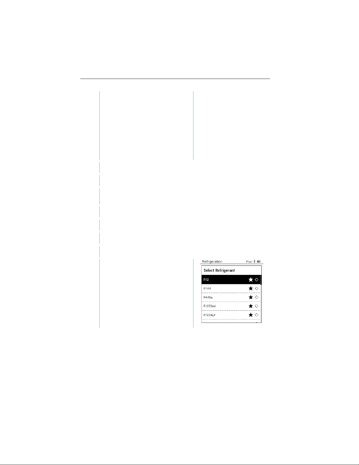
Set refrigerant.
6.1
Press the key [▼] (Rxx) (refrigerant number according to ISO 817).
-
The refrigerant menu opens and the
The measurement menu is displayed.
current refrigerant is highlighted.
17
Find Quality Products Online at: [email protected]
www.GlobalTestSupply.com
Page 16

8 Using the product
6.2
Setting the refrigerant: Press [▲] or
Users have the option of setting up favorite refrigerants on the
must be connected to the instrument via
instrument must remain closed.
-
The newly set refrigerant is displayed in the refrigerant list.
7
Press the [▲] (P=O) key for 2 seconds to zero the sensors.
-
Zeroing takes place.
8
Pressurize the measuring instrument.
-
The measurement starts
-
Measurement results are displayed:
[▼] to select the refrigerant and
press [Menu/Enter] to confirm.
instrument and in the app. These then appear at the beginning of the
refrigerant list.
To do this, the testo Smart App
Bluetooth.
In the refrigerant list (App), now choose the refrigerant as a favorite by
clicking on the star.
The new favorite refrigerant will now be synchronized to the testo 550s
or testo 557s.
Note: During synchronization, the refrigerant list/selection on the
automatically.
• Low/high pressure
• Condensation (CO) and evaporation temperature (EV)
• Suction and liquid line temperature
• Superheating and subcooling
18
Find Quality Products Online at: [email protected]
www.GlobalTestSupply.com
Page 17

). Dependent on this assignment, the display
8.2.2
is recommended for carrying out the measurement. The
The instrument is switched on and the measurement menu is
displayed.
Bluetooth® is enabled.
Hoses are connected.
1
[Menu/Enter]
2
Press [▲] / [▼] to select Measuring
8 Using the product
With zeotropic refrigerants, the evaporation temperature to/Ev is
displayed after complete evaporation. The condensation temperature
tc/Co is displayed after complete condensation.
The measured temperature must be assigned to the superheating or
subcooling side (t
<--> t
oh
cu
will show toh/T1 resp. Δtoh/SH or tcu/T2 resp. Δtcu/SC, depending on the
selected display.
Reading and display illumination flash:
• 1 bar/14.5 psi before reaching critical refrigerant pressure
• When max. permissible pressure of 60 bar/870 psi is exceeded.
All values can be saved and sent in the app. The data can also be
transferred between the app and the testo DataControl software.
Evacuation
Via the Evacuation application, foreign gases and moisture can be removed
from the refrigeration circuit.
The testo 552i
measurement is also possible without the testo 552i, with testo
550s/testo 557s.
accuracy.
However, this is not advisable due to insufficient
Press
.
Mode and press [Menu/Enter] to
confirm.
19
Find Quality Products Online at: [email protected]
www.GlobalTestSupply.com
Page 18
8 Using the product
-
The Measuring Mode menu is
3
Press [▲] / [▼] to select Evacuation and press [Menu/Enter] to
confirm.
-
4
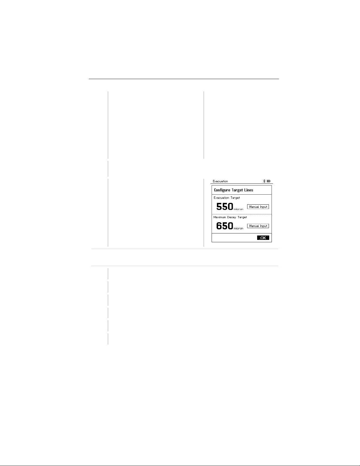
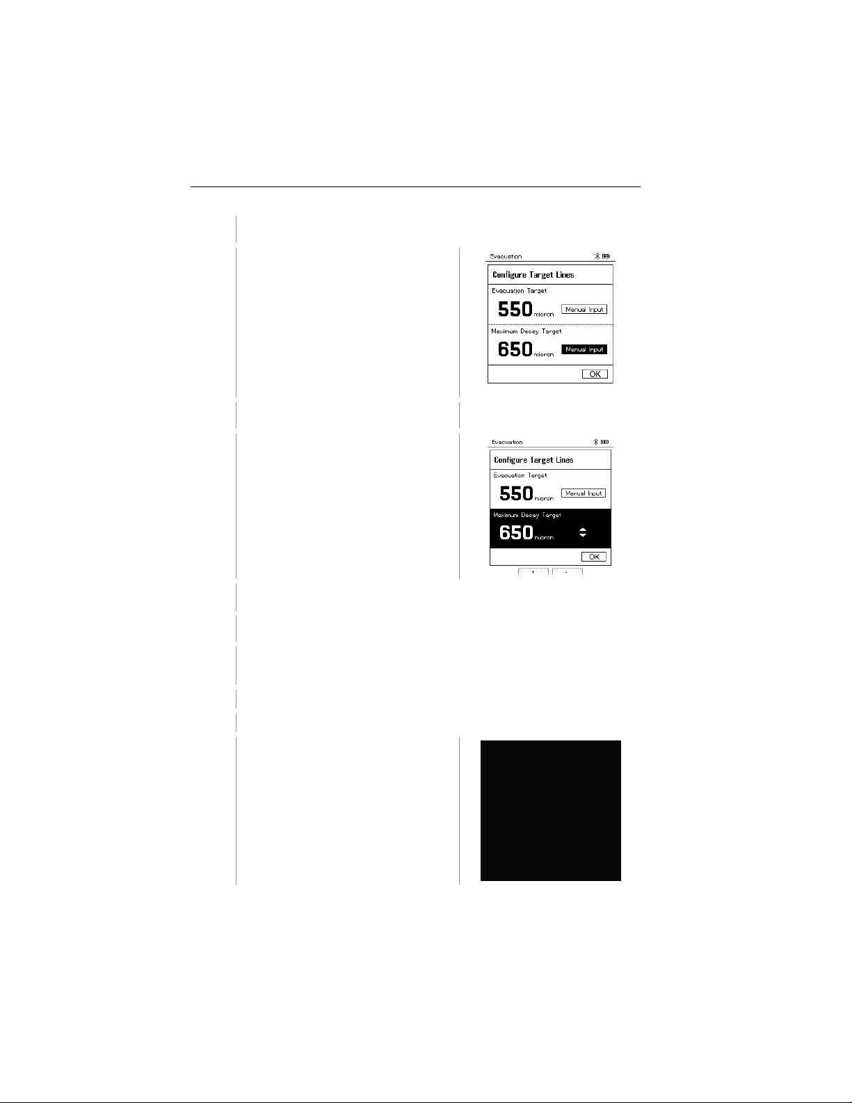
Target Line
4.1
Press the [▲] key and in the Target Line field, select Manual Input.
4.2
Press [Menu/Enter] to confirm.
-
4.3
Press [▲] / [▼] to set the value.
4.4
Press [Menu/Enter] to confirm.
displayed.
The Configure Target Lines menu is
displayed.
20
Evacuation Target will be set at 500 microns as a default. Maximum
decay target will be set at 1000 microns as a default.
Adjust the
value
The field is activated.
Find Quality Products Online at: [email protected]
www.GlobalTestSupply.com
Page 19
8 Using the product
5
Adjust the Maximum Decay Target value
5.1
Press the [▼] button and in the
5.2
[Menu/Enter]
-
The field is activated.
5.3
Press [▲] / [▼] to set the value.
5.4
[Menu/Enter]
6
Confirm the entries in steps 4 and 5:
Press [▼] to select OK and press [Menu/Enter] to confirm.
-
A connection is established with available Bluetooth® probes.
-
testo 552i is switched on and connected automatically.
-
The Evacuation measurement menu
Maximum Decay Target field, select
Manual Input.
Press
to confirm.
Press
is displayed.
to confirm.
21
Find Quality Products Online at: [email protected]
www.GlobalTestSupply.com
Page 20

7
Start measurement: Press the [▼] (Start) key.
-
8
End measurement: Press the [▼] (Stop) key.
-
The measurement result is displayed.
9
Press [Menu/Enter] to return to the main menu.
8.2.3
Smart Probe for measuring the air temperature can be connected. As a
8 Using the product
Once the measuring range 0 to
20,000 microns / 0 to 26.66 mbar is
reached, the current vacuum value is
shown on the instrument display.
The instrument also displays the
current ambient temperature, the
water evaporation temperature which
corresponds to the vacuum reading,
and the delta between these two
temperatures.
Press the [▲] New key to reset the determined values. If necessary, a
test can also be started again.
Pressure Leak Test
The temperature compensated leak test can be used to check the leak tightness
of systems. For this purpose both the system pressure and the ambient
temperature are measured over a defined period of time.
A temperature probe that measures the ambient temperature or a
result, information is provided about the temperature-compensated
differential pressure and about the temperature at the beginning/end of
the test. Due to the temperature compensation, the actual pressure
drop is displayed as delta P. If no temperature probe is connected, you
may also perform the pressure leak test without temperature
compensation.
Surface temperature probes (e.g. testo 115i) can also be used for the
temperature-compensated leak testing, but must not be used to
measure surface temperature. They must be positioned as far as
possible to measure the air temperature. If a surface probe is used, in
the Settings menu of the testo 550s / testo 557s, the Auto Tfac
(Temperature compensation factor) must be switched off, see
section 8.3.4.
22
Find Quality Products Online at: [email protected]
www.GlobalTestSupply.com
Page 21
8 Using the product
The instrument is switched on and the measurement menu is
displayed.
Hoses are connected.
1
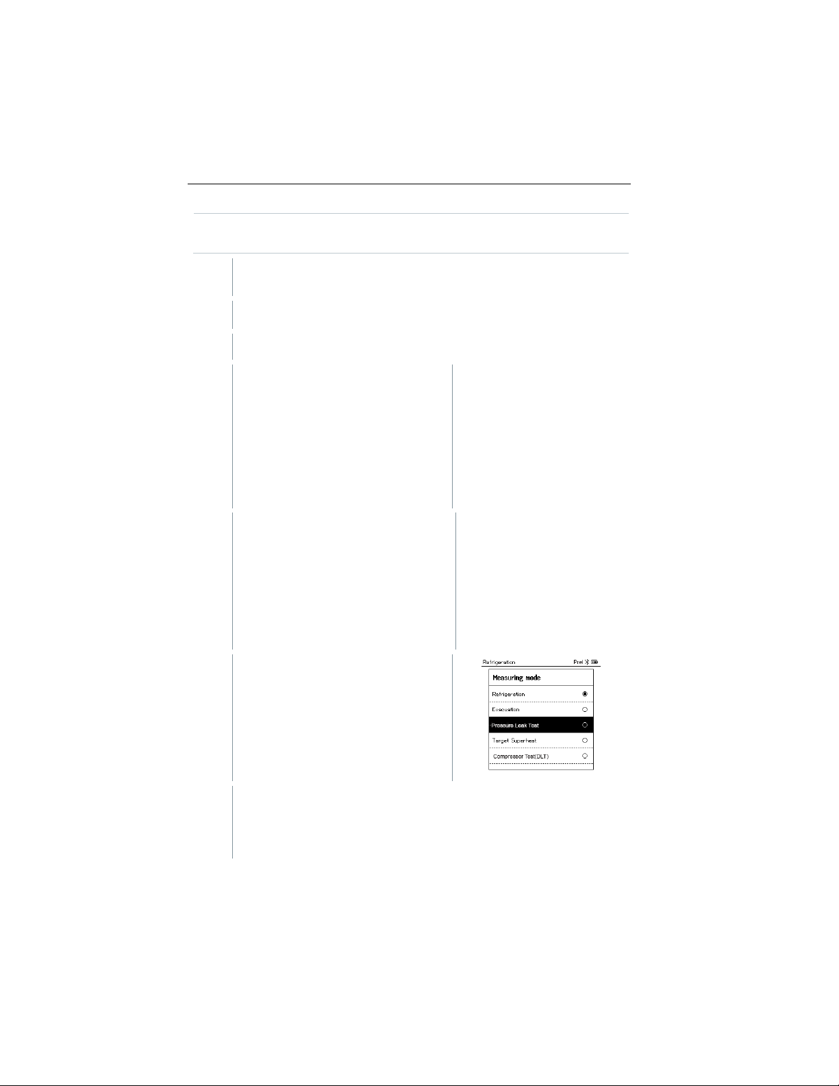
Press [Menu/Enter].
2
Press [▲] / [▼] to select Measuring
-
The Measuring Mode menu is
3
Press [▲] / [▼] to select Pressure
-
For the temperature-compensated leak test, a connection is
compensated leakage testing.
The testo 550s or testo 557s manifold is used to carry out the
measurement.
Mode and press [Menu/Enter] to
confirm.
displayed.
Leak Test and press [Menu/Enter]
to confirm.
established with available Bluetooth® probes. If cable probes are
connected to the instrument, they are prioritized for the compensation.
Please note that only air probes are ideal for temperature-
23
Find Quality Products Online at: [email protected]
www.GlobalTestSupply.com
Page 22
8 Using the product
-
testo 905i / testo 605i is switched on and automatically connected.
can be connected.
-
The Pressure Leak Test menu is displayed.
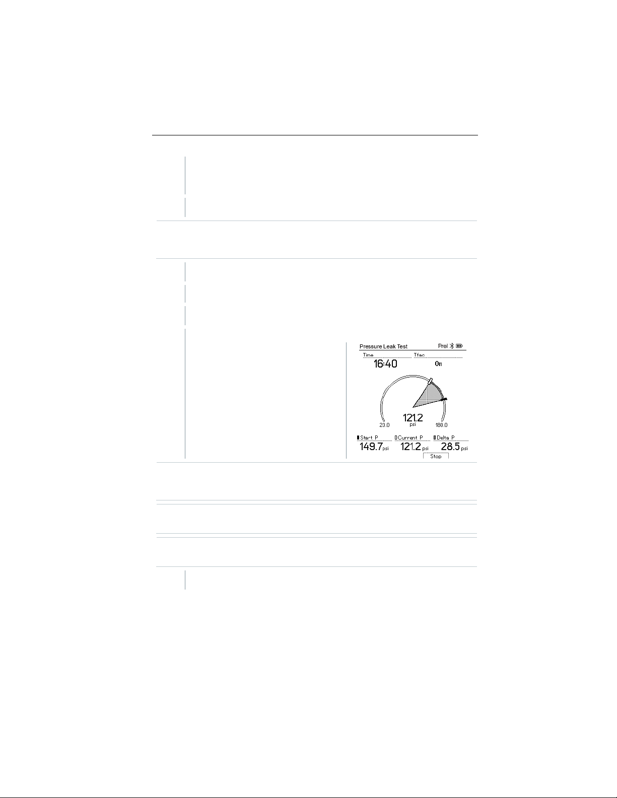
4
Press the [▼] (Start) key.
-
5
Press the [▼] (Stop) key.
-
The leakage test is terminated.
-
The measurement result is
6
Press [Menu/Enter] to return to the main menu.
Other temperature probes compatible with testo 550s / testo 557s
T Comp is shown on the display if a compatible probe is connected via
Bluetooth
measurement result.
The leakage test is carried out.
displayed.
®
or cable. The temperature compensation is used for the
24
Start the measurement once pressure has been achieved. Once
pressure has been reached, press start to enable the Pressure Leak
Test. This will begin the test and the clock.
Press the [▲] New key to reset the determined values. If necessary, a
test can also be started again.
The measurement result can be displayed graphically on the manifold
as well as in the app.
Find Quality Products Online at: [email protected]
www.GlobalTestSupply.com
Page 23

8.2.4
The instrument is switched on and the measurement menu is
displayed.
All connections must be pressureless (ambient pressure).
Bluetooth® is enabled.
1
Press [Menu/Enter].
2
Press [▲] / [▼] to select Measuring
8 Using the product
Target Superheat
This feature makes it possible to connect the testo 550s and testo 557s
manifolds to two additional testo 605i Smart Probes in order to calculate the
target superheat. This application can only be used for split air conditioning
systems/heat pumps with a fixed expansion valve. The two connected testo
605i Smart Probes determine the Outdoor Dry Bulb Temp (ODDB) and Return
Air Wet Bulb (RAWB) values. The target superheat value appears on the
display as a result.
The following are used for the measurement:
• testo 115i (clamp thermometer) or
• fixed cable probes
• testo 605i
Alternatively, the values can be configured manually.
Before each measurement, check that the refrigerant hoses are in
perfect condition.
Before each measurement, zero the pressure sensors.
Mode and press [Menu/Enter] to
confirm.
25
Find Quality Products Online at: [email protected]
www.GlobalTestSupply.com
Page 24
8 Using the product
-
The Measuring Mode menu is
3
Press [▲] / [▼] to select Target Superheat and press [Menu/Enter]
to confirm.
-
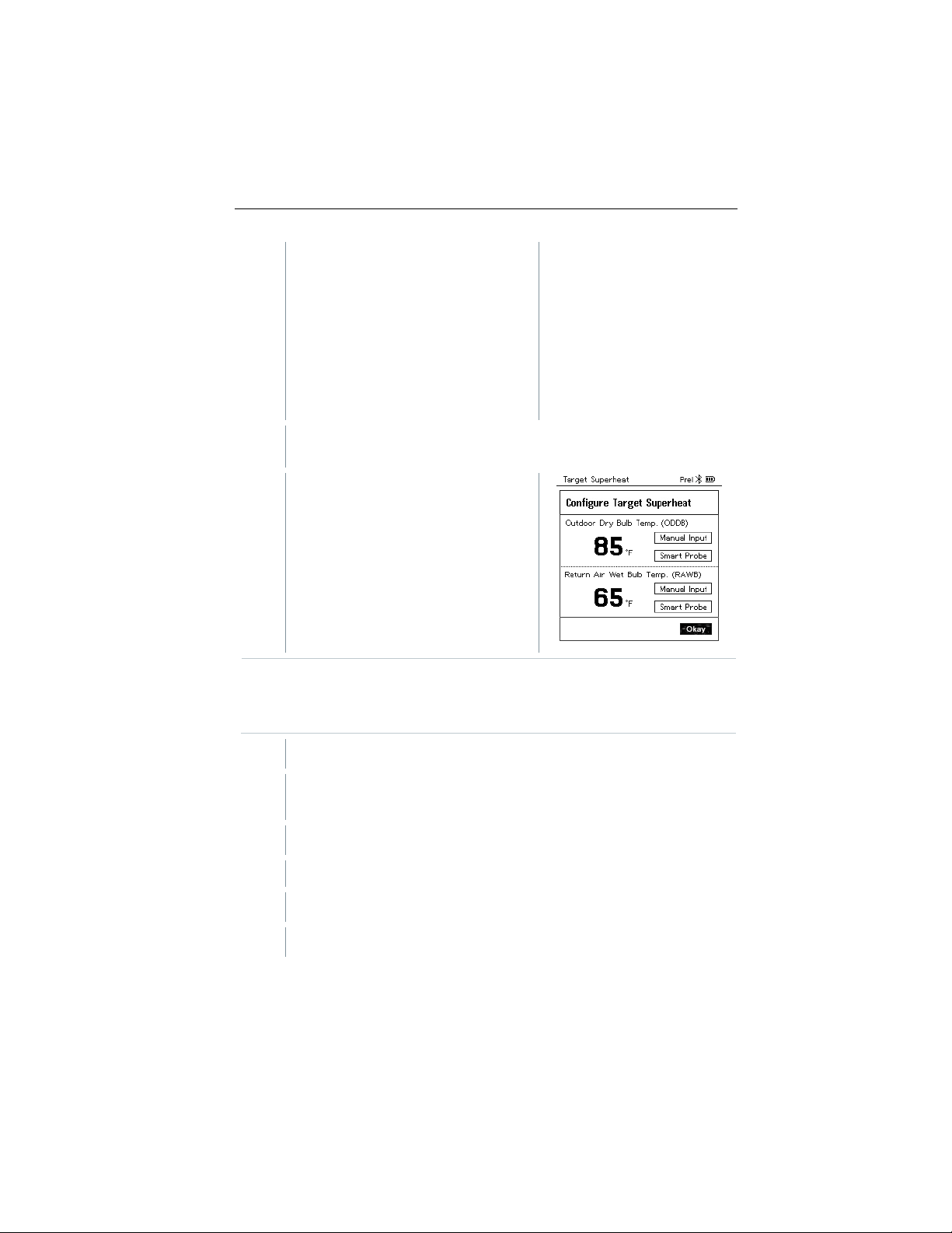
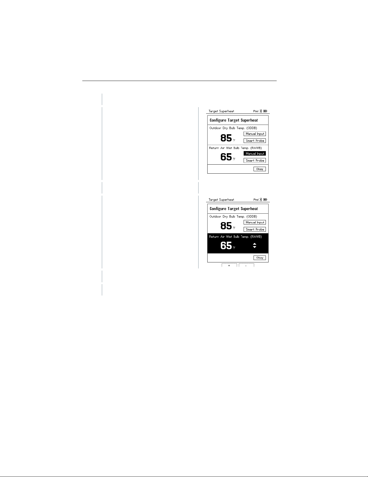
The Configure Target Superheat
4
Adjust values for Outdoor Dry Bulb Temp.
4.1
Press the [▲] key and in the Outdoor Dry Bulb Temp. field, select
4.2
Press [Menu/Enter] to confirm.
-
4.3
Press [▲] / [▼] to set the value.
4.4
Press [Menu/Enter] to confirm.
displayed.
menu is displayed.
26
The values can either be configured manually via Manual Input or
recorded by the testo 605i via Smart Probe. When a Smart Probe is
selected, available testo 650i instruments are displayed for the
connection.
Manual Input.
The field is activated.
Find Quality Products Online at: [email protected]
www.GlobalTestSupply.com
Page 25
8 Using the product
5
Adjust the Return Air Wet Bulb Temp. value
5.1
Press the [▲] / [▼] key and in the
5.2
Press [Menu/Enter] to confirm.
-
5.3
Press [▲] / [▼] to set the value.
5.4
Press [Menu/Enter] to confirm.
Return Air Wet Bulb Temp. field,
select Manual Input.
The field is activated.
27
Find Quality Products Online at: [email protected]
www.GlobalTestSupply.com
Page 26
8 Using the product
6
Confirm the entries in steps 4 and 5:
Press [▼] to select Okay and press [Menu/Enter] to confirm.
-
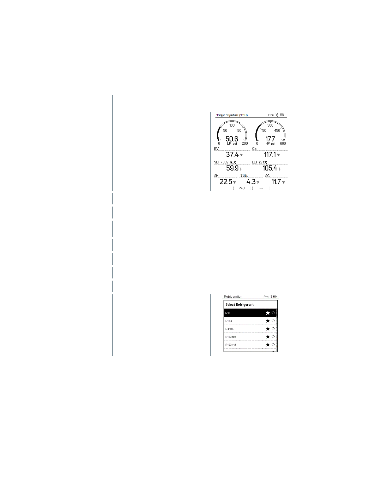
The Target Superheat
7
Connect the refrigerant hoses.
7.1
Close the valve positioners.
7.2
Connect the refrigerant hoses for low-pressure side (blue) and highpressure side (red) to the measuring instrument.
7.3
8
Connect testo 115i/fixed cable probes.
9
Set refrigerant.
9.1
Press the key [▼] (Rxx) (refrigerant number according to ISO 817).
-
The refrigerant menu opens and the
measurement menu is displayed.
Connect the refrigerant hoses to the system.
current refrigerant is highlighted.
28
Find Quality Products Online at: [email protected]
www.GlobalTestSupply.com
Page 27

9.2
Setting the refrigerant: Press [▲] or
-
The newly set refrigerant is displayed in the refrigerant list.
10
Press the [▲] (P=O) key for 2 seconds to zero the sensors.
-
Zeroing takes place.
11
Pressurize the measuring instrument.
-
The measurement starts automatically.
-
8.2.5
The instrument is switched on and the measurement menu is
displayed.
8 Using the product
[▼] to select the refrigerant and
press [Menu/Enter] to confirm.
Measurement results are displayed:
• Low/high pressure
• Condensation and evaporation temperature
• Suction and liquid line temperature
• Superheating and subcooling
• Target superheat TSH
Compressor Test (DLT)
For this mode, 3 temperature probes are used. In addition to the conventional
temperature sensors for superheating and subcooling, an additional temperature
probe must be connected via Bluetooth.
The testo 115i (clamp thermometer) or fixed cable probes are used to
carry out the measurement.
Before each measurement, check that the refrigerant hoses are in
perfect condition.
Before each measurement, zero the pressure sensors.
29
Find Quality Products Online at: [email protected]
www.GlobalTestSupply.com
Page 28
8 Using the product
1
Press [Menu/Enter].
2
Press [▲] / [▼] to select Measuring
-
The Measuring Mode menu is
3
Press [▲] / [▼] to select Compressor Test (DLT) and press
[Menu/Enter] to confirm.
The measurement menu is
4
Connect the refrigerant hoses.
4.1
Close the valve positioners.
4.2
Connect the refrigerant hoses for low-pressure side (blue) and highpressure side (red) to the measuring instrument.
4.3
Connect the refrigerant hoses to the system.
Mode and press [Menu/Enter] to
confirm.
displayed.
displayed.
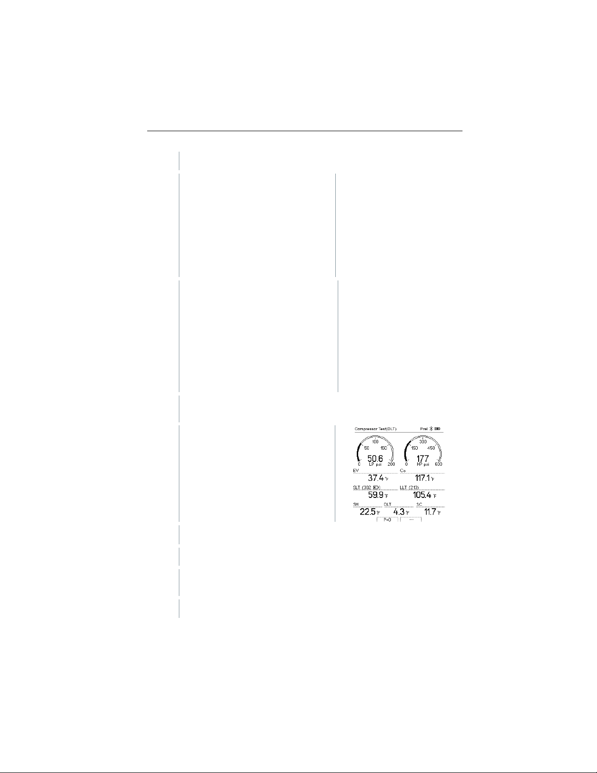
The DLT temperature is shown on the
display.
30
Find Quality Products Online at: [email protected]
www.GlobalTestSupply.com
Page 29
8 Using the product
5
Connect the testo 115i or fixed cable probes and third temperature
probe to the compressor outlet.
6
Set refrigerant.
6.1
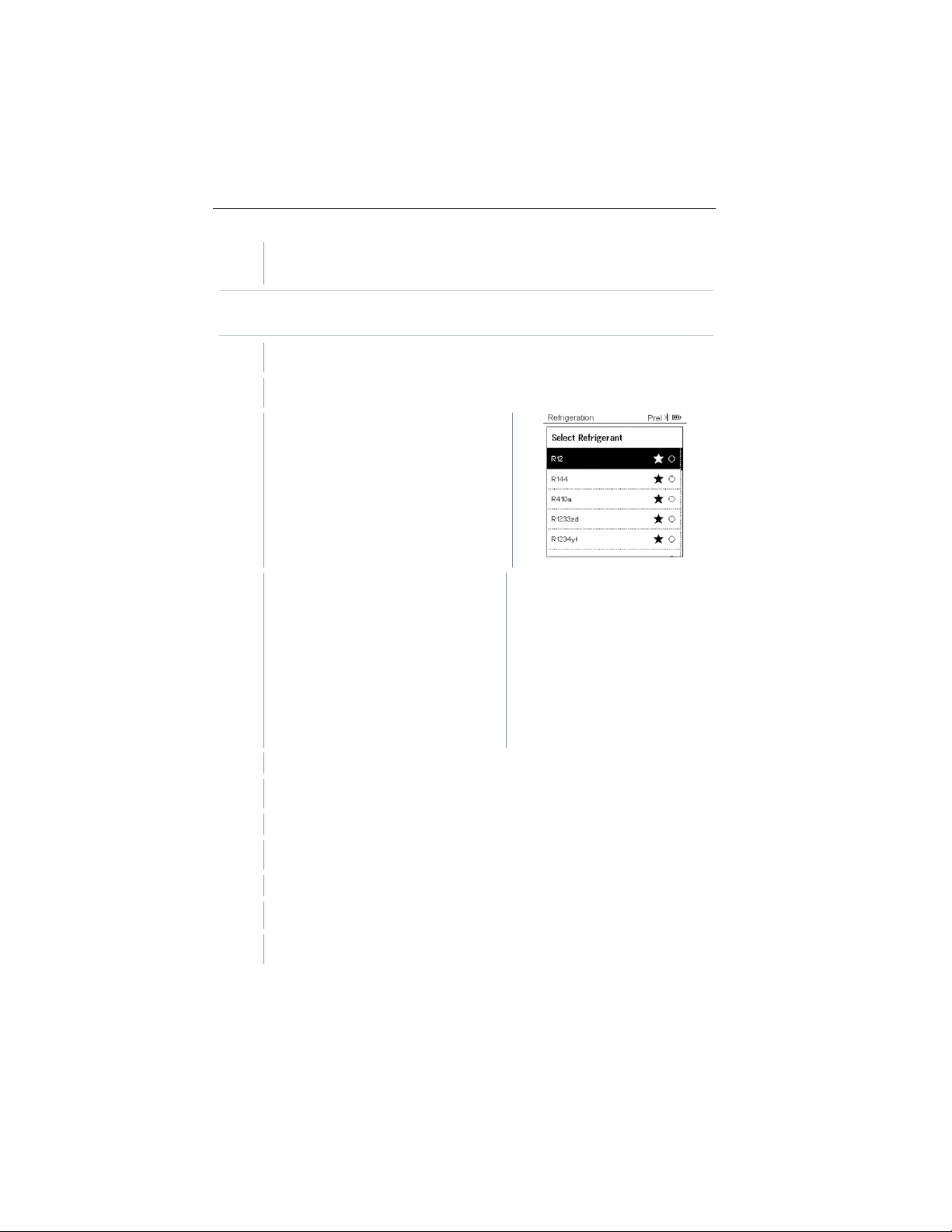
Press the key [▼] (Rxx) (refrigerant number according to ISO 817).
-
The refrigerant menu opens and the
6.2
Setting the refrigerant: Press [▲] or
-
The newly set refrigerant is displayed in the refrigerant list.
7
Press the [▲] (P=O) key for 2 seconds to zero the sensors.
-
Zeroing takes place.
8
Pressurize the measuring instrument.
-
The measurement starts automatically.
-
9
Press [Menu/Enter] to return to the main menu.
Recommended to use a wireless probe for the compressor outline line
to not impede the fan blade.
current refrigerant is highlighted.
[▼] to select the refrigerant and
press [Menu/Enter] to confirm.
The measurement result is displayed.
31
Find Quality Products Online at: [email protected]
www.GlobalTestSupply.com
Page 30

8 Using the product
8.2.6
The instrument is switched on and the measurement menu is
displayed.
Preparing for measurement
been followed/carried out.
testo 115i is switched on.
1
Place the testo 115i at the measuring points.
2
Press [Menu/Enter].
3
Press [▲] / [▼] to select Measuring
-
The Measuring Mode menu is
4
Press [▲] / [▼] to select Delta T and press [Menu/Enter] to confirm.
Delta T
Temperature 1 and temperature 2 are measured. The difference is shown on
the display as the delta temperature.
The testo 115i (clamp thermometer) or fixed cable probes are used to
carry out the measurement.
The steps described in the
section have
Mode and press [Menu/Enter] to
confirm.
displayed.
32
Find Quality Products Online at: [email protected]
www.GlobalTestSupply.com
Page 31
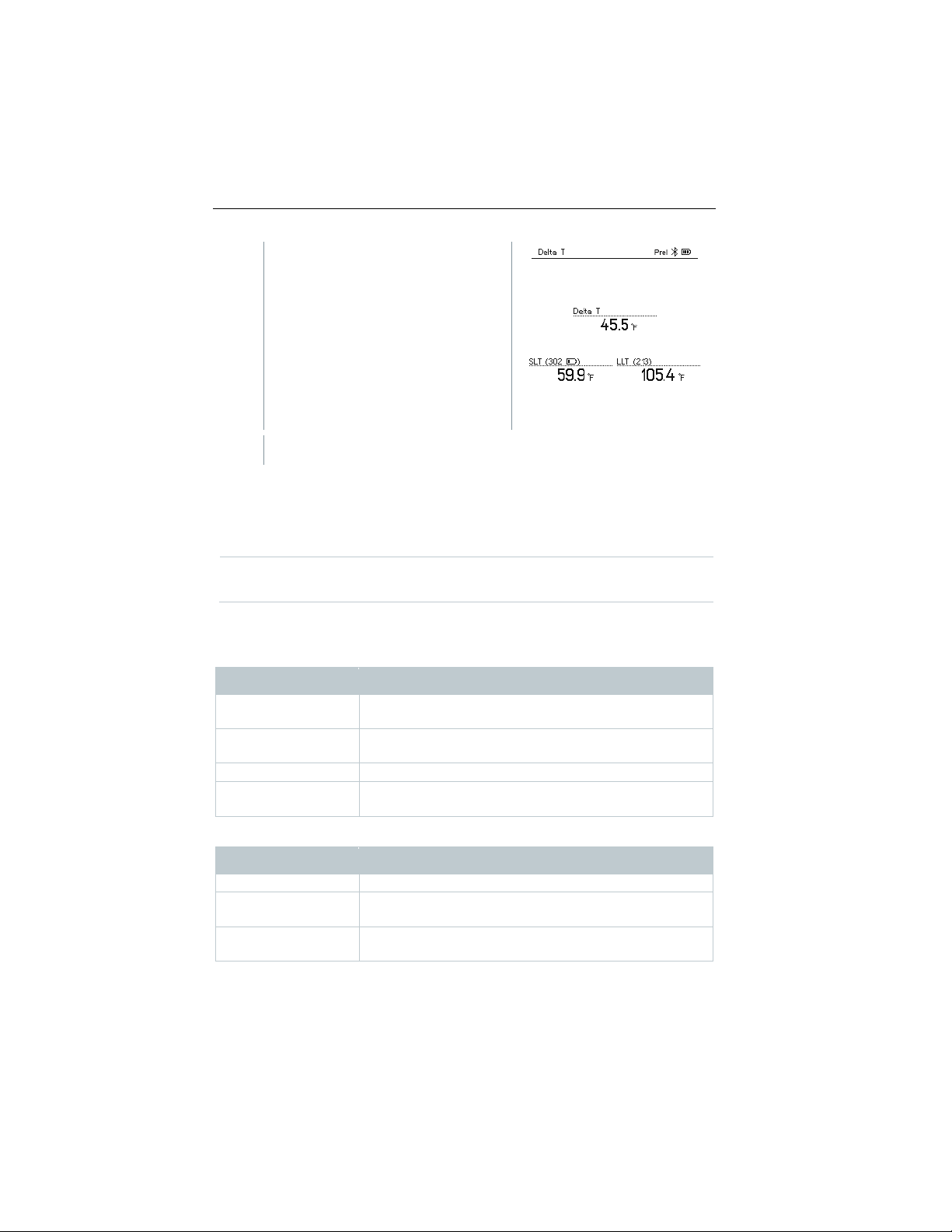
-
The measurement result is
5
Press [Menu/Enter] to return to the main menu.
8.3
8.3.1
0560 2115 02
testo 115i – clamp thermometer with smartphone
operation
0560 2605 02
testo 605i – thermohygrometer with smartphone
operation
0564 2552 01
testo 552i – vacuum Smart Probe
0560 1905
testo 905i – temperature probe with smartphone
operation
0613 1712
Robust air temperature probe (NTC)
0613 5505
Clamp probe (NTC) for temperature measurements on
pipes (Ø ¼ to 1 ¼ inch), 5ft m fixed cable
0613 5506
Clamp probe (NTC) for temperature measurements on
pipes (Ø ¼ to 1 ¼ inch), 16ft fixed cable
8 Using the product
displayed.
Bluetooth
testo 550s / testo 557s have the option of establishing a Bluetooth® connection
with wireless probes as well as a connection to the testo Smart App at the same
time.
If the testo 550s or testo 557s is used with Smart Probes, they must
be at least 8 in apart.
Probes compatible with the instrument
Smart Probes
Order no. Designation
NTC probes
Order no. Designation
33
Find Quality Products Online at: [email protected]
www.GlobalTestSupply.com
Page 32

0613 5507
2 x clamp probes (NTC) for temperature
cable
0613 4611
Temperature probe with Velcro (NTC)
0613 5605
Pipe wrap probe (NTC), measuring range:
-58 to 248 °F
surfaces, measuring range: -58 to 248 °F
8.3.2
the App for iOS instruments in the App Store or for Android
8 Using the product
Order no. Designation
measurements on pipes (Ø ¼ to 1 ¼ inch), 5ft fixed
0613 1912 Waterproof surface temperature probe (NTC) for flat
Establishing a connection
®
To establish a connection via Bluetooth
smartphone with the testo Smart App installed on it.
You can get
instruments in the Play Store.
Compatibility:
Requires iOS 12.0 or later/Android 6.0 or later, requires
Bluetooth
®
4.0.
Once the connection between the app and the testo 550s and testo 557s has
been successfully established, the app is in second screen mode. This is
indicated by a yellow frame in the app.
This means that all measurement data from the manifold is being mirrored on
the app. The measurement can now be controlled from both instruments. It is
possible to carry out the following actions:
• Start measurement
• Stop measurement
• Reset measurement
• Configure measurement
• Select refrigerant
, you need a tablet or
34
Find Quality Products Online at: [email protected]
www.GlobalTestSupply.com
Page 33
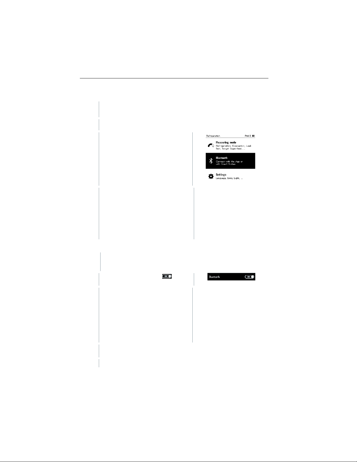
8.3.3
The instrument is switched on and the measurement menu is
displayed.
1
Press [Menu/Enter].
2
[▲] / [▼]
Bluetooth
-
The Bluetooth menu is displayed.
8.3.3.1
The Bluetooth menu is selected.
1
[Menu/Enter]
-
In the On/Off switch icon, is
displayed.
2
Enable Bluetooth®: Press [▼] to
-
When the Bluetooth® icon is shown on the display, Bluetooth is
switched on.
-
Bluetooth® automatically searches for and connects available probes.
Switching on/off
Press
and press [Menu/Enter] to confirm.
Switching on
to select
8 Using the product
:
activate the [Completed] button and
press [Menu/Enter] to confirm.
35
Find Quality Products Online at: [email protected]
www.GlobalTestSupply.com
Page 34

8 Using the product
-
After opening the App, the instrument is automatically connected if it is
smartphone/tablet via settings beforehand.
8.3.3.2
The Bluetooth® menu is activated.
1
[Menu/Enter]
-
In the On/Off switch icon, is
displayed.
3
Disable Bluetooth®: Press [▼] to
-
When the Bluetooth® icon is not shown on the display, Bluetooth® is
switched off.
8.3.3.3
The Bluetooth® menu is activated (in the On/Off switch icon, is
1
Press [▼] to select Manual probe selection.
within range. The instrument does not have to be connected to the
Switching off
activate the [Competed] button and
press [Menu/Enter] to confirm.
Manual probe selection
If this menu is activated, it appears before a measurement.
displayed.
Enable function: Via [Menu/Enter], set the switch to [ON].
An info window with the available probes appears before each
measurement to be carried out. The information must be
confirmed by pressing [Menu/Enter]/[Okay].
Disable function: Via [Menu/Enter], set the switch to [OFF].
®
If the advanced Bluetooth
instrument automatically connects to the first compatible Smart
Probe.
settings are switched off, the
36
Find Quality Products Online at: [email protected]
www.GlobalTestSupply.com
Page 35
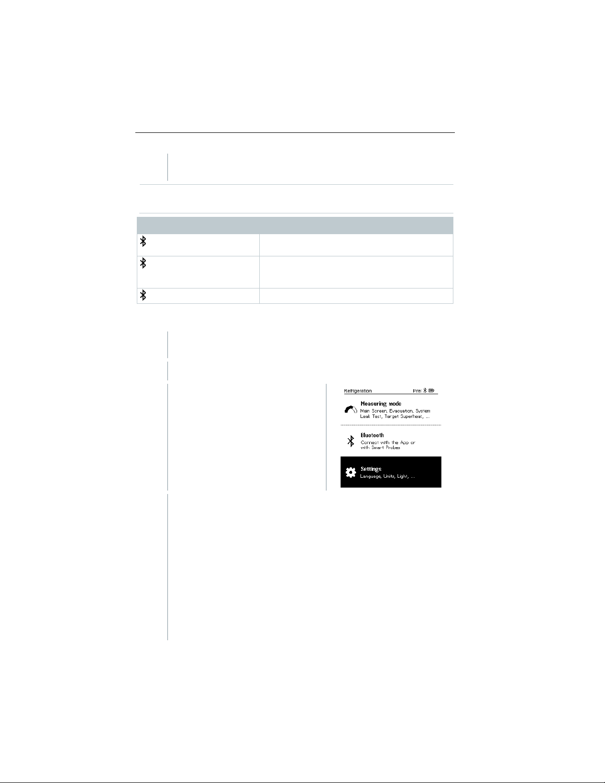
2
Press [▼] to click on the [Completed] button and press [Menu/Enter]
to confirm.
There is no Bluetooth® connection, or a
potential connection is being searched for.
There is a Bluetooth® connection, the number
next to it.
is not displayed
8.4
The instrument is switched on and the measurement menu is
displayed.
1
Press [Menu/Enter].
2
Select Settings: Press [▼] and then
-
The Settings menu is displayed.
In the Bluetooth® menu, you will obtain further information.
Display Explanation
flashes
8 Using the product
is permanently displayed
Settings
[Menu/Enter] to confirm.
Available settings:
• Duration
• Brightness
• Auto Off
• Auto Tfac (Temperature compensation factor)
• Units
• Language
• Setup Wizard
• Factory Settings
• Instrument
of connected Bluetooth® probes is displayed
Bluetooth® is disabled.
37
Find Quality Products Online at: [email protected]
www.GlobalTestSupply.com
Page 36
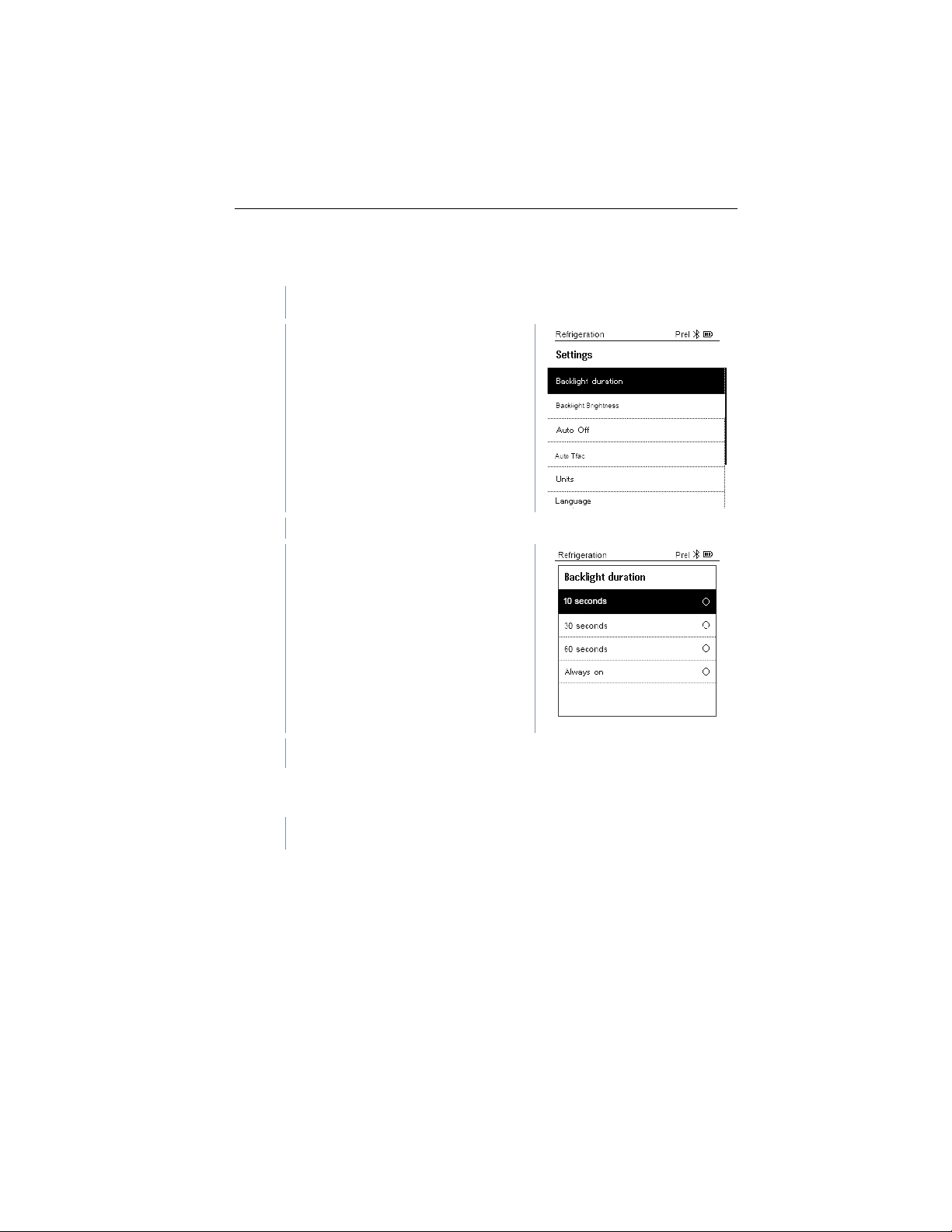
8.4.1
The Settings menu is activated.
1
Press [▲] / [▼] to select Backlight
-
Menu properties are displayed.
2
[▲] / [▼]
3
Press [ESC]: 1x main menu view, 2 x measurement menu view.
8.4.2
The Settings menu is activated.
8 Using the product
Backlight Duration
Set the backlight duration for the display.
duration and press [Menu/Enter] to
confirm.
Press
backlight duration and press
[Menu/Enter] to confirm.
to select the
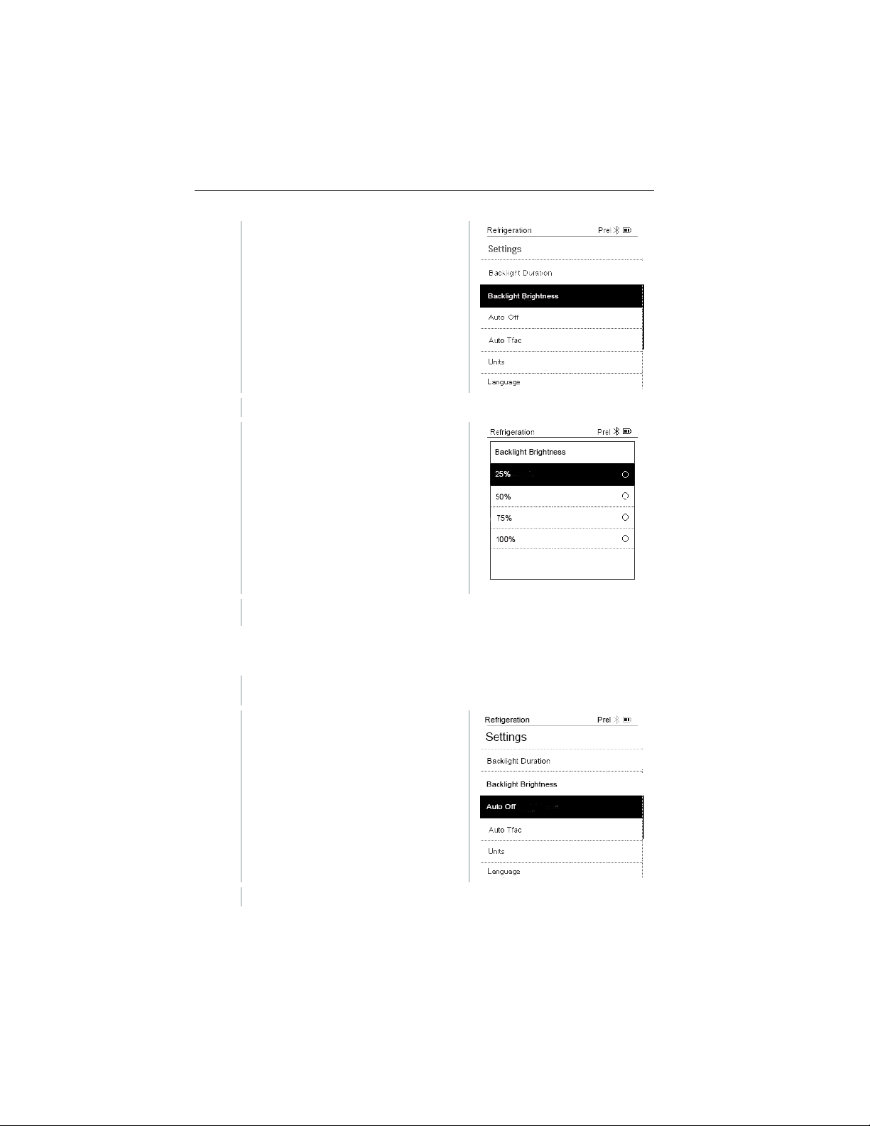
Backlight Brightness
Set the brightness for the display.
38
Find Quality Products Online at: [email protected]
www.GlobalTestSupply.com
Page 37
8 Using the product
1
Press [▲] / [▼] to select the
-
Menu properties are displayed.
2
Press [▲] / [▼] to select the
3
Press [ESC]: 1x main menu view, 2 x measurement menu view.
8.4.3
The Settings menu is activated.
1
Press [▲] / [▼] to select [Auto OFF]
-
Menu properties are displayed.
Backlight brightness and press
[Menu/Enter] to confirm.
brightness value (25%, 50%, 75%,
100%) and press [Menu/Enter] to
confirm.
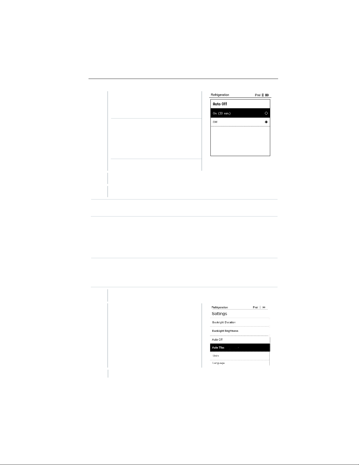
You can manage the energy consumption for your instrument yourself.
Auto Off
and press [Menu/Enter] to confirm.
39
Find Quality Products Online at: [email protected]
www.GlobalTestSupply.com
Page 38
8 Using the product
2
Press [▲] / [▼] to select Auto OFF
measured and no key has been
long as pressure is present, the
3
Confirm selection by pressing [Menu/Enter].
4
Press [ESC]: 1x main menu view, 2 x measurement menu view
Unsaved readings are lost when the measuring instrument is switched
8.4.4
Surface temperature probe
An NTC temperature probe (accessory) must be connected to measure
The Settings menu is activated.
1
Select Auto Tfac and press
-
Menu properties are displayed.
On: The instrument automatically
switches off after 30 minutes of
inactivity.
The instrument switches off
automatically if no pressure is
pressed within 10 minutes. As
instrument remains on.
• Off: Continuous operation
off.
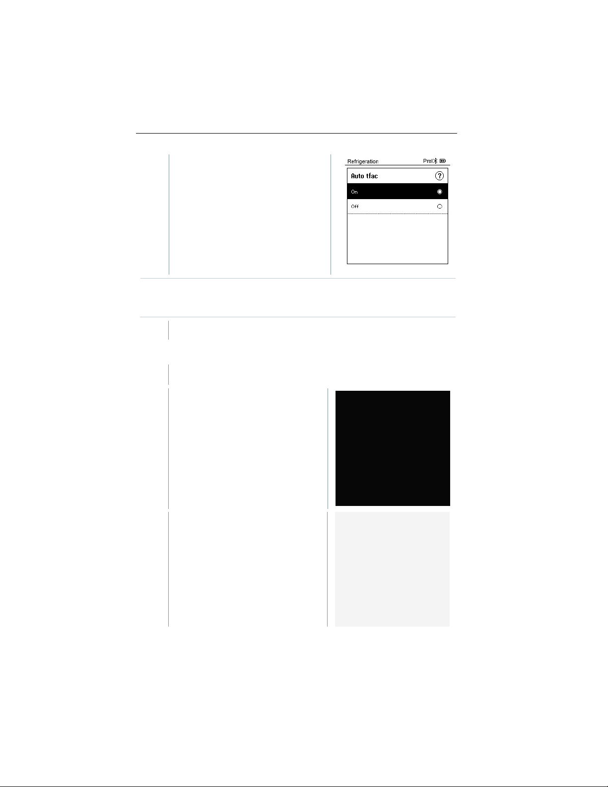
Auto Tfac (Temperature compensation
factor)
A surface compensation factor has been set in the measuring instrument to
reduce the measuring errors in the main field of applications. This reduces
measuring errors when using surface temperature probes.
the pipe temperature and to automatically calculate superheating and
subcooling.
[Menu/Enter] to confirm.
Find Quality Products Online at: [email protected]
40
www.GlobalTestSupply.com
Page 39
2
Press [▲] / [▼] to activate
3
Press [ESC]: 1x main menu view, 2 x measurement menu view
8.4.5
1
[▲] / [▼]
[Units]
-
Menu properties are displayed.
8 Using the product
(On)/deactivate (Off) Auto Tfac and
press [Menu/Enter] to confirm.
Press [▲] / [▼] to select the question mark icon and press
[Menu/Enter] to open. You will obtain further information on
temperature compensation.
Units
The Settings menu is activated.
Press
press [Menu/Enter] to confirm.
to select
and
41
Find Quality Products Online at: [email protected]
www.GlobalTestSupply.com
Page 40

8 Using the product
Temperature
°C, °F
Set unit for temperature.
psi, kPa, MPa,
bar
Prel, Pabs
Depending on the chosen unit for
pressure displays.
bar (Pabs)
Set the current absolute pressure
Internet).
Micron, mbar,
hPa, Pa
3
Press [ESC]: 1 x Units menu, 2 x main menu view, 3 x measurement
menu view.
8.4.6
The Settings menu is activated.
1
Press [▲] / [▼] to select
-
Menu properties are displayed.
Adjustable units
Measurement
parameter
Pressure
Pressure mode
Absolute
pressure
Vacuum
pressure
Language
Unit Description
Set unit for pressure.
pressure:
Change between absolute and relative
(current air pressure values for your
region can be obtained, for example,
from the local weather service or on the
Torr, mTorr
inH2O, in Hg,
[Language] and press [Menu/Enter]
to confirm.
42
Find Quality Products Online at: [email protected]
www.GlobalTestSupply.com
Page 41

2
Select language: [▲] / [▼] and
press [Menu/Enter] to confirm.
3
[ESC]
Units
menu view.
8.4.7
The Settings menu is activated.
1
Press [▲] / [▼] to select [Setup
-
Language selection opens.
2
Press [▲] / [▼] to select the
-
The units for the respective country are set automatically.
Selecting the language activates
the appropriate presetting of the
units of measurement.
Press
Setup Wizard
Wizard] and press [Menu/Enter] to
confirm.
: 1 x
8 Using the product
menu, 2 x main menu view, 3 x measurement
language.
43
Find Quality Products Online at: [email protected]
www.GlobalTestSupply.com
Page 42

-
Barcode is displayed and the testo
8.4.8
The Settings menu is activated.
1
Press [▲] / [▼] to select [Restore
-
Menu properties are displayed.
2
Start [Restore Factory Reset]:
8 Using the product
Smart App can be downloaded from
the respective app store.
Factory Settings
The instrument is reset to the factory settings.
Factory Reset] and press
[Menu/Enter] to confirm.
Press [▲] / [▼] to select [Do a
factory reset] and press
[Menu/ESC] to confirm.
Press [Back] to quit the process.
44
Find Quality Products Online at: [email protected]
www.GlobalTestSupply.com
Page 43

-
[Restore Factory Reset] is carried
3
See Setup Wizard.
8.4.9
The Settings menu is activated.
1
Press [▲] / [▼] to select [Device
-
The Versions Info menu is displayed.
2
Press [ESC]: 1 x Units menu, 2 x main menu view, 3 x measurement
menu view.
8 Using the product
out.
Instrument
Info] and press [Menu/Enter] to
confirm.
The following information can be viewed:
• Serial number
• Firmware version
• Refrigerant version
• BLE Version)
45
Find Quality Products Online at: [email protected]
www.GlobalTestSupply.com
Page 44

9
9.1
1
2
Display of the measurement period
3 Display of calculated measurement results
4
5 Can be controlled with different function keys
6 Device status bar
7
8
One level back
9 Smart App
Smart App
App – user interface
Open main menu
Reading for each probe
Configuration
Edit reading display
Further symbols on the user interface (without numbering)
Exit view
Share report
46
Find Quality Products Online at: [email protected]
www.GlobalTestSupply.com
Page 45
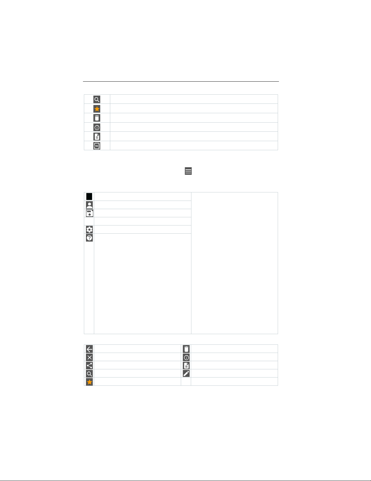
Search
Display report
9.2
Measure
Customer
Memory
Sensors
Settings
Help and Information
One level back
Delete
Exit view
Further information
Share measurement data/reports
Display report
Search
Edit Favorite
9 Smart App
Favorite
Delete
Further information
Multiple selection
Main menu
The Main menu can be accessed via the icon at top left. To exit the main
menu, select a menu or right-click on the guided menus. The last screen
displayed is shown.
Additional icons:
47
Find Quality Products Online at: [email protected]
www.GlobalTestSupply.com
Page 46

9.3
Basic view
Volume flow – duct
Volume flow – outlet
Differential temperature (ΔT)
Differential pressure (ΔT)
Refrigeration
Target superheat
Cooling and heating output
Leakage test
Evacuation
9 Smart App
Measurement menu
The testo Smart App has permanently installed measurement programs. These
enable the user to carry out convenient configuration and implementation of
specific measuring tasks.
The testo Smart App offers the following Measurement menus:
Find Quality Products Online at: [email protected]
48
www.GlobalTestSupply.com
Page 47

9.3.1
9.3.1.1
1
menu
2
Change of display
3
Reading for selected
channel
4
Measurement
measurement unit
5
Graphic with selected
channels and 4 Y-axes
6
Status bar
7
configuration menu
8
Selection of other
channels
9
Time axis
10
New/Start/Stop/Save
9 Smart App
Basic view
In the Basic view application menu, the current measuring values can be read,
recorded and saved. The Basic view is particularly suitable for fast,
uncomplicated measurements without the specific requirements of a standardcompliant measurement.
All Bluetooth® probes compatible with the testo Smart App are displayed in the
Basic view.
In all application menus, apart from the volume flow measurement, there are
three different screens for the measurement - Live (or also Basic view), Graphic
and Table.
Graphic view
In the Graphic view, the values for a maximum 4 channels can be displayed
simultaneously in a chronological trend graph. All measured parameters can be
displayed in the Graphic view via the channel selection (click on one of the four
selection fields). Once a measurement parameter has been selected, the value
is updated automatically.
The Zoom touch function allows individual parts of the graphic to be viewed in
more detail or time progressions to be displayed compactly.
Open the main
parameter and
Open the
button
49
Find Quality Products Online at: [email protected]
www.GlobalTestSupply.com
Page 48
9.3.1.2
1
menu
2
Change of display
3
Column with date and
time
4
Arrow keys to go
the table
5
Status bar
6
configuration menu
7
Probe ID measurement unit
8
Measuring values
9
New/Start/Stop/Save
button
9.3.2
9 Smart App
Table view
Open the main
directly to the end of
Open the
Refrigeration
The Refrigeration application is used to determine the following system
measuring values:
• Low-pressure side: Evaporation pressure, refrigerant evaporation
temperature to/Ev (T evap.)
• Evaporation pressure: Measured temperature toh/T1
• Evaporation pressure: Superheating Δtoh/SH
• High-pressure side: Condensation pressure, refrigerant condensation
temperature tc/Co (T condens.)
• Condensation pressure: Measured temperature tcu/T2
• Condensation pressure: Subcooling Δtcu/SC
The testo 115i clamp thermometer is used for the measurement.
An NTC temperature sensor (accessory) must be connected for
measuring the pipe temperature and for automatic calculation of
superheating and subcooling. Testo Smart Probes (e.g. testo 115i) can
be used.
50
Find Quality Products Online at: [email protected]
www.GlobalTestSupply.com
Page 49

9 Smart App
1
2
Click on Refrigeration.
3
4
Make the required settings.
5
Click on Apply Configuration.
Before each measurement, check that the refrigerant hoses are in
flawless condition.
Before each measurement, zero the pressure sensors. All connections
must be pressureless (ambient pressure). Press the button [▲] (P=O)
for 2 seconds to zero the sensors.
Click on Measure.
The Refrigeration measurement menu opens.
Click on .
Configuration menu opens.
51
Find Quality Products Online at: [email protected]
www.GlobalTestSupply.com
Page 50

9 Smart App
6
Set refrigerant.
You have the option of setting up favourite refrigerants in the App.
list (App).
7
Click on Start.
subcooling side (toh <--> tcu). Dependent on this assignment, the display
52
These then appear at the beginning of the refrigerant list.
To do this, click on the asterisk next to the refrigerant in the refrigerant
The newly set refrigerant is displayed in the refrigerant list.
The measurement starts.
Values currently being measured are displayed.
Measured values can be saved or a new measurement can be started.
With zeotropic refrigerants, the evaporation temperature to/Ev is
displayed after complete evaporation/the condensation temperature
tc/Co is displayed after complete condensation.
The measured temperature must be assigned to the superheating or
Find Quality Products Online at: [email protected]
www.GlobalTestSupply.com
Page 51

9 Smart App
will show toh/T1 resp. Δtoh/SH or tcu/T2 resp. Δtcu/SC, depending on the
9.3.3
1
2
Click on Target superheat.
3
Reading and display illumination flash:
selected display.
• 1 bar/14.5 psi before reaching critical refrigerant pressure
• When max. permissible pressure of 60 bar/870 psi is exceeded.
Target Superheat
This feature allows the calculation of target superheat in conjunction with the
App and additional testo 605i Smart Probes. This application can only be used
for split air conditioning systems/heat pumps with a fixed expansion valve. The
two connected testo 605i Smart Probes determine the ODDB and RAWB
values. As a result, the target superheat appears in the App.
The following are used for the measurement:
• testo 115i (clamp thermometer)
• testo 605i
Before each measurement, check that the refrigerant hoses are in
flawless condition.
Before each measurement, zero the pressure sensors.
Click on Measure.
The Target superheat measurement menu opens.
Click on .
Configuration menu opens.
53
Find Quality Products Online at: [email protected]
www.GlobalTestSupply.com
Page 52

9 Smart App
4
Make the required settings.
5
Click on Apply Configuration.
6
Set refrigerant.
The newly set refrigerant is displayed in the refrigerant list.
54
Find Quality Products Online at: [email protected]
www.GlobalTestSupply.com
Page 53

7
Click on Start.
9.3.4
al pressure drop is displayed as delta P. If no temperature sensor is
connected, you may also perform the tightness test without temperature
1
2
Click on Leakage test.
3
9 Smart App
The measurement starts.
Values currently being measured are displayed.
Measured values can be saved or a new measurement can be started.
Pressure Leak Test
The temperature compensated tightness test can be used to check the leak
tightness of systems. For this purpose both the system pressure and the
ambient temperature are measured over a defined period of time.
For this purpose a temperature sensor to measure the ambient
temperature may be connected (recommendation: Deactivate the
surface compensation factor and use an NTC air probe or Bluetooth
temperature Smart Probes) or Smart Probe for air temperature
measurement. This provides information about the temperaturecompensated differential pressure and the temperature at the
beginning/end of the test. Due to the temperature compensation, the
actu
®
Surface temperature probes (e.g. testo 115i) can also be used for the
compensation.
temperature-compensated tightness testing, but must not be used for
measuring surface temperature. They must be positioned as far as
possible to measure the air temperature.
The 550i, 550s or 557s manifold is used to perform the measurement.
Click on Measure.
The Leakage test measurement menu opens.
Click on .
Configuration menu opens.
55
Find Quality Products Online at: [email protected]
www.GlobalTestSupply.com
Page 54

9 Smart App
4
Make the required settings.
5
Click on Apply Configuration.
7
Click on Start.
The measurement starts.
Values currently being measured are
displayed.
Measured values are saved. The values can be exported or a report
can be created.
56
Find Quality Products Online at: [email protected]
www.GlobalTestSupply.com
Page 55

9.3.5
1
2
Click on Evacuation.
3
4
Make the required settings.
5
Click on Apply Configuration.
9 Smart App
Evacuation
With the Evacuation application, foreign gases and moisture can be removed
from the refrigeration circuit.
Click on Measure.
The Evacuation measurement menu opens.
Click on .
Configuration menu opens.
57
Find Quality Products Online at: [email protected]
www.GlobalTestSupply.com
Page 56

9 Smart App
6
Click on Start.
9.4
9.4.1
1
2
The measurement starts.
Values currently being measured are
displayed.
Measured values can be saved or a new measurement can be started.
Customer
In the Customer menu, all customer and measuring site information can be
created, edited and deleted. Fields marked with * are mandatory. Without any
information in this field, no customers or measuring sites can be stored.
Creating and editing a customer
Click on .
58
Main menu opens
Click on Customer.
The Customer menu opens.
Find Quality Products Online at: [email protected]
www.GlobalTestSupply.com
Page 57

9 Smart App
3
Click on + New customer.
4
Store all relevant customer data.
5
Click on Save.
9.4.2
1
2
3
Click on + New customer.
4
Click on the right tab Measuring point.
A new customer can be created.
The new customer was saved.
Creating and editing measuring sites
Click on .
Main menu opens
Click on Customer.
The Customer menu opens.
59
Find Quality Products Online at: [email protected]
www.GlobalTestSupply.com
Page 58

9 Smart App
5
Click on + New measuring site.
6
Store all relevant measuring site information.
7
Click on right tab Parameters.
8
Select further parameters.
9
Click on Save.
A new measuring site can be created.
60
For the duct, outlet or duct with k-factor measuring sites, further
parameter settings can be implemented.
The new measuring site has been saved.
Find Quality Products Online at: [email protected]
www.GlobalTestSupply.com
Page 59

9.5
9.5.1
The Memory menu is open.
1
2
Enter the customer name or measuring site or date/time in the search
1
2
Click on the required measurement.
3
4
Acknowledge the information.
9 Smart App
Memory
In the Memory menu, you can call up all the measurements stored on the
mobile device, analyze them in detail and also create and save csv data and
PDF reports. When clicking on a measurement, an overview of the
measurement results is displayed.
Searching for and deleting measurement
results
In the Memory menu, all stored measurements are sorted by date and time.
Click on .
Deleting
Search field with measurements opens.
field.
The result is displayed.
Click on .
A check box is displayed in front of each measurement.
A tick is displayed in the respective box.
Click on .
Information window is displayed.
Selected measurements were deleted.
61
Find Quality Products Online at: [email protected]
www.GlobalTestSupply.com
Page 60

9.6
9.6.1
The App is connected to an instrument.
1
2
3
Click on one of the displayed probes.
9 Smart App
Sensors
All sensors used with the App can be found in the Sensors menu. There,
you can view general information about currently connected probes as well as
recently connected probes.
Information
Information is stored for each probe.
Click on .
62
Main menu opens.
Click on Sensors.
The Sensors menu opens.
Information is displayed about the model, order number, serial number
and firmware version.
Find Quality Products Online at: [email protected]
www.GlobalTestSupply.com
Page 61

9.6.2
The probe is connected to the App.
1
2
3
Click on one of the displayed probes.
4
Click on the Settings tab.
5
Click on one of the displayed probes.
9.7
9.7.1
1
2
Click on Language.
3
Click on the required language.
Settings
Settings can also be made for each probe.
Click on .
Main menu opens.
Click on Sensors.
The Sensors menu opens.
Settings appear that can be changed if necessary.
Settings
Language
9 Smart App
Click on Settings.
The Settings menu opens.
A window with different languages opens.
The required language is set.
63
Find Quality Products Online at: [email protected]
www.GlobalTestSupply.com
Page 62
9.7.2
1
2
Click on Measurement settings.
3
Click on the required settings and change if necessary.
4
9.7.3
1
2
Click on Company details.
3
Click on the required data and enter if necessary.
4
9.7.4
1
2
Click on Privacy settings.
9 Smart App
Measurement settings
Click on Settings.
The Settings menu opens.
A window with different basic settings for measurement opens.
The required measurement settings are set.
Exit Measurement settings.
Company details
Click on Settings.
The Settings menu opens.
A window with company details opens.
The required measurement settings are set.
Exit Company details.
Privacy settings
Click on Settings.
64
The Settings menu opens.
A window with privacy settings opens.
Find Quality Products Online at: [email protected]
www.GlobalTestSupply.com
Page 63

3
Activate or deactivate the required settings.
4
9.8
9.8.1
1
2
Click on Instrument information.
>
Use the slider to activate or deactivate Update for connected
9.8.2
1
2
Click on Tutorial.
9 Smart App
The required settings are set.
Exit Privacy settings.
Help and Information
Under Help and Information, you will find information about the instrument, and
the tutorial can be called up and implemented. This also where legal information
can be found.
Instrument information
Click on Help and Information.
Automatic updates for instruments can be enabled or disabled.
The Help and Information menu opens.
The current App version, Google Analytics instance ID, refrigerant
version and update are displayed for the connected instrument.
Tutorial
instruments.
Click on Help and Information.
The Help and Information menu opens.
The tutorial shows you the most important steps prior to
commissioning.
65
Find Quality Products Online at: [email protected]
www.GlobalTestSupply.com
Page 64

9.8.3
1
2
Click on Exclusion of liability.
9.9
9.9.1
9.9.1.1
9.9.1.2
9 Smart App
Exclusion of liability
Click on Help and Information.
The Help and Information menu opens.
The data protection information and licence usage information is
displayed.
testo DataControl archiving software
The free testo DataControl measurement data management and analysis
software enhances the functionality of the testo Smart App measuring
instrument with lots of useful functions:
• Manage and archive customer data and measuring site information
• Read out, evaluate and archive measurement data
• Presenting readings in graphic form
• Create professional measurement reports from the existing measurement
data
• Conveniently add pictures and comments to measurement reports
• Data import from and data export to the measuring instrument
System requirements
Administrator rights are required for installation.
Operating system
The software can be run on the following operating systems:
• Windows
• Windows® 8
• Windows
The computer must meet the requirements of the operating system in each
case. The following requirements must also be met:
• Interface USB 2 or higher
• DualCore processor with minimum 1 GHz
• Minimum 2 GB RAM
• Minimum 5 GB available hard disk space
66
®
7
®
10
PC
Find Quality Products Online at: [email protected]
www.GlobalTestSupply.com
Page 65

• Screen with a resolution of at least 800 x 600 pixels
9.9.2
To transfer the data from the App to testo DataControl, both
1
Open testo Smart App on the smartphone or tablet.
2
Open the testo DataControl archiving software on the PC.
3
Click on Select instrument.
Procedure
instruments must be in the same network.
For example: A notebook with installed testo DataControl and a
smartphone with installed testo Smart App are connected to the same
WLAN.
9 Smart App
An overview with available instruments opens.
67
Find Quality Products Online at: [email protected]
www.GlobalTestSupply.com
Page 66

10 Maintenance
4
Select instrument.
5
Click on Transfer data to DataControl and delete from instrument.
10
10.1
10.2
Do not use any aggressive cleaning agents or solvents! Mild household
>
If the housing of the instrument is dirty, clean it with a damp cloth.
A safety notice is displayed.
Data has been successfully transferred.
Maintenance
Calibration
The testo 550s / testo 557s is supplied with a factory calibration
certificate as standard.
Recalibration once every 12 months is recommended in many
applications.
This can be carried out by Testo Industrial Services (TIS) or other
certified service providers.
Cleaning the instrument
cleaning agents and soap suds may be used.
68
Find Quality Products Online at: [email protected]
www.GlobalTestSupply.com
Page 67

10.3
Keeping connections clean
>
> Keep screw connections clean and free of grease and other
deposits; clean with a damp cloth as required.
10.4
>
> Carefully blow out oil residues in the valve block using
compressed air.
10.5
>
Check the instrument regularly for leaks. Keep to the permissible
pressure range!
>
> Calibrate the instrument regularly (recommendation: once a
year).
10.6
The instrument is switched off.
1
Fold out the suspension hook,
2
Remove the spent (rechargeable) batteries and insert new ones (3 x
the polarity!
3
Attach and close the battery compartment lid (the clip must click into
place).
4
Switch the instrument on.
Removing oil residues
10 Maintenance
Ensuring measuring accuracy
> Testo Customer Service will be happy to help you as required.
Changing batteries/rechargeable
batteries
release the clip and remove the
battery compartment lid.
AAA batteries / Micro / R03) into the battery compartment. Observe
69
Find Quality Products Online at: [email protected]
www.GlobalTestSupply.com
Page 68

11
Measurement parameters
Pressure: kPa/MPa/bar/psi
micron / inHg / Pa
Sensor
testo 550s
testo 557s
Connections: 3
Valves: 3
Connections: 4
Valves: 4
Pressure: 2 x pressure sensor
connection
Measuring cycle
0.5 s
Interfaces
Pressure ports: 3 x 7/16" UNF, 1 x 5/8" UNF
External vacuum probe
Measuring ranges
HP/LP pressure measuring range: -100 to
Vacuum measuring range: 0 to 20,000 microns
Overload
65 bar; 6500 kPa; 6.5 MPa; 940 psi
Resolution
Resolution pressure: 0.01 bar/0.1
to 20,000 microns)
11 Technical data
Technical data
Feature Value
Temperature: °C/°F/K
Vacuum: hPa / mbar/ Torr / mTorr / inH2O /
Temperature: 2 x NTC
Vacuum: via external probe
Up to 4 Smart Probes via Bluetooth®
NTC measurement
70
6000 kPa/-0.1 to 6 Mpa/-1 to 60 bar (rel)/-14.7
to 870 psi
Temperature measuring range: -50 to +150 °C
/ -58 to 302 °F
Temperature measuring range of testo 115i:
-40 to +150 °C / -40 to 302 °F
psi/1 kPa/0.001 Mpa
Resolution temperature: 0.1 °C / 0.1 °F / 0.1 K
Vacuum resolution:
1 micron (from 0 to 1000 microns) 10 microns
(from 1000 to 2000 microns) 100 microns (from
2000 to 5000 microns) 500 microns (from 5000
to 10,000 microns) 5000 microns (from 10,000
Find Quality Products Online at: [email protected]
www.GlobalTestSupply.com
Page 69

Feature Value
Accuracy (nominal
Pressure: ±0.5% of full scale value (±1 digit)
1000 microns)
Measurable media
Measurable media: all media that are stored in
ammonia.
Ambient conditions
Operating temperature: -20 to 50 °C / -4 to
Humidity application range: 10 to 90 %RH
Housing
Material: ABS/PA/TPE
Weight: 930 g (without batteries)
IP class
54
Power supply
Current source: Rechargeable batteries /
vacuum probe connected)
Auto off
10 min, if enabled
Display
type: Illuminated LCD
Response time: 0.5 s
Directives, standards and
EU Directive: 2014/30/EU
You can find the EU declaration of
11 Technical data
temperature 22 °C/71.6 °F)
Temperature (-50 to 150 °C): ±0.5 °C (±1 digit),
±0.9 °F (±1 digit),
testo 115i temperature: ±2.3 °F (-4° to 185 °F) /
±1.3 °C (-20 to +85 °C),
Vacuum: ±(10 microns + 10% of m.v.) (100 to
the testo 557. Not measurable: ammonia
(R717) and other refrigerants which contain
122 °F
-10 to 50 °C / 14 to 122 °F (vacuum)
Storage temperature: -20 to +60 °C/-4 to
140 °F
Dimensions: approx. 235 x 121 x 80 mm
batteries 4 x 1.5 V type AA / Mignon / LR6
Battery life:
> 250 h (display illumination off, Bluetooth off,
vacuum probe not connected)
> 100 h (display illumination on, Bluetooth on,
tests
conformity under the product-specific
downloads on the Testo website:
71
Find Quality Products Online at: [email protected]
www.GlobalTestSupply.com
Page 70

11 Technical data
No. of refrigerants
~ 90
Selectable refrigerants in the
R114
R407C
R444B
R12
R407F
R448A
R123
R407H
R449A
R1233zd
R408A
R450A
R1234yf
R409A
R452A
R1234ze
R410A
R452B
R124
R414B
R453a
R125
R416A
R454A
R13
R420A
R454B
R134a
R421A
R454C
R22
R421B
R455A
R23
R422B
R458A
R290
R422C
R500
R32
R422D
R502
R401A
R424A
R503
R401B
R427A
R507
R402A
R434A
R513A
R402B
R437A
R600a
R404A
R438A
R718 (H2O)
R407A
R442A
R744 (CO2)
R11
R227
R417A
FX80
R236fa
R417B
I12A
R245fa
R417C
R1150
R401C
R422A
R1270
R406A
R426A
R13B1
R407B
R508A
R14
R407D
R508B
R142B
R41
R600
R152a
R411A
RIS89
R161
R412A
SP22
R170
R413A
Available refrigerants
Feature Value
instrument
72
Find Quality Products Online at: [email protected]
www.GlobalTestSupply.com
Page 71
12
12.1
Question
Possible causes/solution
> Change the batteries.
> Change the batteries.
measuring range.
The value is above the permissible
measuring range.
12.2
12.2.1
E 11
Remove the batteries and reinsert them in the instrument. If the
E 12
E 13
E 14
E 15
12.2.2
E 30
An old version is still running on the testo 550s / testo 557s. Update
department.
persists, please contact our service department.
E 32
Remove the batteries and reinsert them in the instrument. If the
error persists, please contact our service department.
Tips and assistance
Questions and answers
12 Tips and assistance
flashes
The device switches itself off.
Below range lights up instead of the
measurement parameter display
Above range lights up instead of the
measurement parameter display
Error Codes
Main screen
Code Possible cause / solution
error persists, please contact our service department.
Status view
Batteries are almost empty.
Residual capacity of batteries too low.
The value is below the permissible
measuring range.
> Keep within the permissible
measuring range.
> Keep within the permissible
Code Possible cause / solution
the instrument. If the error persists, please contact our service
E 31 testo 550s / testo 557s is still using the old version refrigerant. If you
wish to use the latest refrigerant, please update it again. If the error
73
Find Quality Products Online at: [email protected]
www.GlobalTestSupply.com
Page 72

13 Support
12.3
Description
Order no.
Clamp probe for temperature measurement on pipes
(1.5 m)
Clamp probe for temperature measurement on pipes (5
m)
2 x clamp temperature probes kit (NTC) for digital
manifolds
Pipe wrap probe with Velcro tape for pipe diameters of
up to max. 75 mm, Tmax +75 °C, NTC
Precise, robust NTC air probe
0613 1712
Magnetic strap
0564 1001
Accessories and spare parts
0613 5505
0613 5506
0613 5507
0613 4611
Water tight NTC surface probe 0613 1912
Spare valve set 0554 5570
External vacuum probe 0564 2552
For a complete list of all accessories and spare parts, please refer to the product
catalogues and brochures
74
Find Quality Products Online at: [email protected]
www.GlobalTestSupply.com
 Loading...