

Page 1
testo 480 · Climate measuring instrument
Instruction manual
Page 2

2
Page 3

1 Contents
1 Contents
1 Contents ................................................................................................... 3
2 Safety and the environment .................................................................... 5
2.1. About this document ........................................................................ 5
2.2. Ensure safety ................................................................................... 6
2.3. Protecting the environment .............................................................. 7
3 Specifications .......................................................................................... 8
3.1. Use .................................................................................................. 8
3.2. Technical data ................................................................................. 8
4 Product description ............................................................................... 11
4.1. Overview........................................................................................ 11
4.1.1. Hand instrument ............................................................................................ 11
4.1.2. Instrument connections and interfaces ........................................................... 12
4.1.3. Controls ......................................................................................................... 13
4.1.4. Display ........................................................................................................... 14
5 First steps .............................................................................................. 16
5.1. Commissioning .............................................................................. 16
5.2. Getting to know the product ........................................................... 19
5.2.1. Navigating in the menu .................................................................................. 19
5.2.2. Calling up a function ...................................................................................... 20
5.2.3. Exit the menu ................................................................................................. 20
5.2.4. Switching to another tab ................................................................................ 20
5.2.5. Entering values .............................................................................................. 20
5.2.6. Saving values ................................................................................................ 21
6 Using the product .................................................................................. 22
6.1. Performing settings ........................................................................ 22
6.2. Setting the measurement display .................................................. 23
6.2.1. Calculated measurement parameters ............................................................ 24
6.3. Favourites tab ................................................................................ 25
6.4. Probe menu ................................................................................... 26
6.5. Explorer menu ............................................................................... 27
3
Page 4

1 Contents
6.6.
Measurements & Measuring programs ......................................... 30
6.6.1. Retaining (“holding”) measurement values .................................................... 31
6.6.2. Quick back-up ................................................................................................ 31
6.6.3. Measuring program ........................................................................................ 31
6.6.4. Grid measurement ......................................................................................... 34
6.6.5. Turbulence measurement .............................................................................. 38
6.6.6. Pitot tube measurement ................................................................................. 39
6.6.7. Measurement with the funnel ......................................................................... 40
6.6.8. Pressure measurement ................................................................................. 40
6.6.9. CO2 measurement ......................................................................................... 41
6.6.10. WBGT measurement ..................................................................................... 41
6.6.11. PMV/PPD measurement ................................................................................ 43
6.6.12. Saving measurement values .......................................................................... 47
6.6.13. Printing measurement values ........................................................................ 49
6.6.14. Display measuring values graphically ............................................................ 49
6.6.15. Transferring measurement values ................................................................. 51
7 Maintaining the product ....................................................................... 52
7.1.1. Battery care ................................................................................................... 52
7.1.2. Carrying out humidity adjustment................................................................... 52
7.1.3. Carrying out a firmware update ...................................................................... 54
8 Tips and assistance .............................................................................. 55
8.1. Questions and answers ................................................................ 55
8.2. Accessories and spare parts ......................................................... 56
4
Page 5
2 Safety and the environment
2 Safety and the environment
2.1. About this document
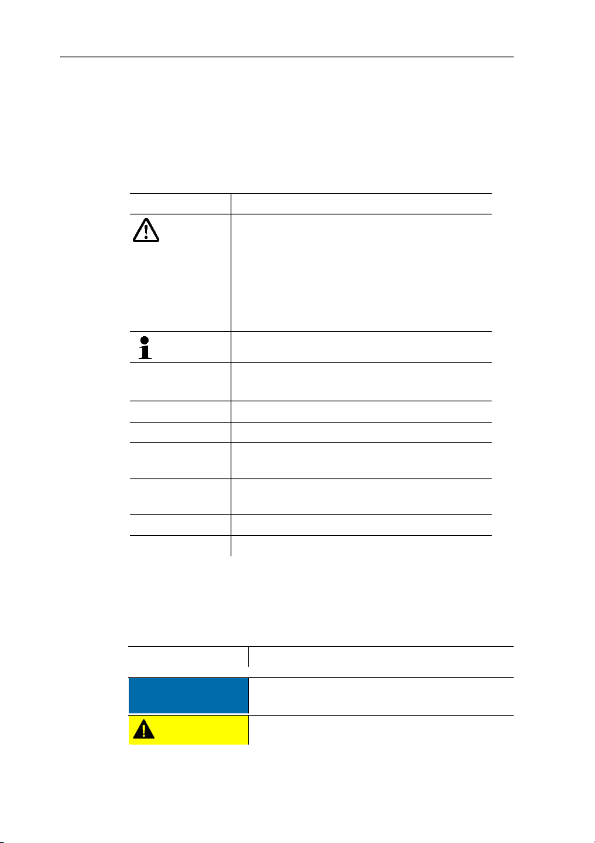
Symbols and writing standards
Representation Explanation
Warning advice, risk level according to the
signal word:
Warning! Serious physical injury may occur.
Caution! Slight physical injury or damage to
the equipment may occur.
> Implement the specified precautionary
measures.
Note: Basic or further information.
1. ...
2. ...
Action: more steps, the sequence must be
followed.
> ... Action: a step or an optional step.
- ... Result of an action.
Menu Elements of the instrument, the instrument
display or the program interface.
[OK] Control keys of the instrument or buttons of
the program interface.
... | ... Functions/paths within a menu.
“...” Example entries
Warnings
Always pay attention to information that is marked by the following
warnings with warning pictograms. Implement the specified
precautionary measures.
Representation Explanation
CAUTION
NOTICE
indicates circumstances that may lead to
damage to the products
indicates potential minor injuries
5
Page 6

2 Safety and the environment
2.2. Ensure safety
> Only operate the product properly, for its intended purpose and
within the parameters specified in the technical data. Do not
use any force.
> The objects to be measured or the measurement environment
may also pose risks: Note the safety regulations valid in your
area when performing the measurements.
> Do not perform contact measurements on non-insulated, live
parts.
> Do not store the product together with solvents. Do not use any
desiccants.
> Carry out only the maintenance and repair work on this
instrument that is described in the documentation. Follow the
prescribed steps exactly. Use only original spare parts from
Testo.
> Temperatures given on probes relate only to the measuring
range of the sensors. Do not expose handles and feed lines to
temperatures in excess of 40 °C (104 °F), unless they are
expressly permitted for higher temperatures.
> After the final measurement, allow probes and probe shafts to
cool down sufficiently in order to avoid burns from the hot
sensor tip or the probe shaft.
> Improper use of rechargeable batteries can lead to destruction
or injuries by means of current surges, fire or escaping
chemicals. The following instructions must be observed to avoid
such hazards:
• Only use in accordance with the directions in the instruction
manual.
• Do not short, take apart or modify.
• Do not expose to heavy impacts, water, fire or temperatures
above 60 °C.
• Do not store in the proximity of metal objects.
• Do not use leaky or damaged rechargeable batteries. In the
event of contact with battery acid: Thoroughly wash affected
area with water and consult a doctor, if necessary.
6
Page 7

• Only charge in the instrument or the recommended charging
station.
• Immediately stop the charging process if this is not
completed in the given time.
• In the event of improper function or signs of overheating,
immediately remove the rechargeable battery from the
measuring instrument/charging station. Caution:
Rechargeable battery may be hot!
Use
> Please read this documentation through carefully and
familiarize yourself with the product before putting it to use. Pay
particular attention to the safety instructions and warning advice
in order to prevent injuries and damage to the products.
> Keep this document to hand so that you can refer to it when
necessary.
> Hand this documentation on to any subsequent users of the
2.3. Protecting the environment
product.
> Dispose of faulty rechargeable batteries/spent batteries in
accordance with the valid legal specifications.
> At the end of its useful life, send the product to the separate
collection for electric and electronic devices (observe local
regulations) or return the product to Testo for disposal.
2 Safety and the environment
7
Page 8

3 Specifications
3 Specifications
3.1. Use
The testo 480 is a measuring instrument for measuring climaterelated parameters. The testo 480 is ideal for comfort level
measurements for the workplace evaluation and flow
measurements in and at ventilation and air-conditioning systems.
The instrument is only to be used by qualified expert personnel.
3.2. Technical data
Then product must not be used in explosive environments!
Hand-held instrument
Feature Values
Measurement
parameters
• Temperature (°C, °F, difference-°C,
difference-°F)
• Humidity (%RH, td°C, td°F, wet bulb °C,
wet bulb °F, g/m
3
, g/ft3, g/kg, g/lb, kJ/kg,
BTU/lb, ppm, Vol%)
• Flow velocity (m/s, ft/m)
• Pressure (Pa, hPa, mbar, kPa, bar, psi,
inH2O, inHg, mmH2O, Torr)
• CO
(ppm, Vol%)
2
• Lux (Lux, footcandle)
Sensor connections • 2x temperature (TC type K)
• 1x differential pressure
• 3x digital probes (flow, humidity,
temperature, CO
, Lux, absolute
2
pressure)
Interfaces • Mini USB
• Infrared for testo report printer
• SD card
• Mains connection
Internal memory
capacity
Rechargeable battery
life
1.8 GB (approx. 60,000,000 measuring
values)
Approx. 17 h (hand instrument without
probe with 50% display brightness)
8
Page 9

Feature Values
Measuring cycle 0.5 s
Operating
0 to +40 °C
temperature
Storage temperature -20 to +60 °C
Dimensions 81 mm x 235 mm x 39 mm
Housing material ABS, TPE, PMMA
Weight Approx. 435 g
IP protection class 30 (with connected probes)
Integrated measurement (at 22 °C, ±1 digit)
Feature Values
Temperature (TC
type K; internal
reference point
measurement:
measuring range 0 to
+40 °C, accuracy
±0.5 °C)
Measuring range: -200.0 to +1370.0 °C
Accuracy: ±(0.3 °C + 0.1 % of meas. val.)
Resolution: 0.1 °C
The accuracy information applies in
a similar, stable temperature state.
Plugging in the main unit, charging
the battery or adding digital probes
can distort this temporarily, and
additional errors may occur.
3 Specifications
Differential pressure Measuring range: -25 to +25 hPa
Accuracy1: ±(0,3 Pa + 1% of meas. val.)
Resolution: 0.001 hPa
The accuracy specification applies
immediately after zeroing of the
sensor. For long-term
measurements, mains operation
with fully-charged battery is
recommended.
Temperature coefficient: <0.01%
FS/K typical
1
Source: DIN EN ISO 7726
9
Page 10
3 Specifications
Feature Values
Absolute pressure Measuring range: +700 to +1100 hPa
Accuracy: ±3 hPa
Resolution: 0.1 hPa
Standards, tests, warranty
Feature Values
EU Directive 2004/108/EC
Vibration IEC 60068-2-6
Warranty
2 years, warranty conditions: see
www.testo.com/warranty
Mains unit (0554 8808) for continuous measurements and
battery charging
Feature Values
Output voltage 5 V / 4 A
EU Directive 2004/108/EC
Warranty period
2 years, warranty conditions: see
www.testo.com/warranty
Lithium battery
Feature Values
Charging option In instrument
Charging current Max. 2.5 A per battery
Discharge current Max. 1.5 A per battery
Charge time Approx. 8 h
Battery life
Approx. 17 h (hand instrument without
probe with 50% display brightness)
Ambient temperature 0 – 40 °C / 32 – 104 °F
Long-term storage
<23 °C / <73 °F
temperature
EU Directive 2004/108/EC
Warranty period
2 years, warranty conditions: see
www.testo.com/warranty
10
Page 11
4 Product description
4.1. Overview
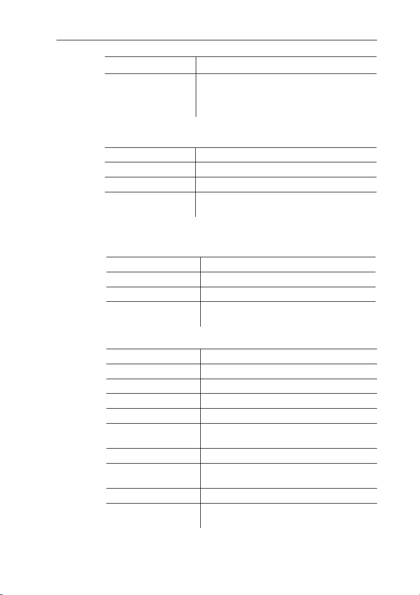
4.1.1. Hand instrument
4 Product description
1 Display
2 Mini USB interface (right-hand side of instrument)
3 Control buttons and trackpad (navigation field)
4 SD card slot (right-hand side of instrument)
5 Magnetic holder (on back)
CAUTION
Damage to other equipment caused by strong magnets!
> Keep well away from products that could be damaged by the
effects of magnetism (e.g. pacemakers, monitors, computers or
credit cards).
11
Page 12
4 Product description
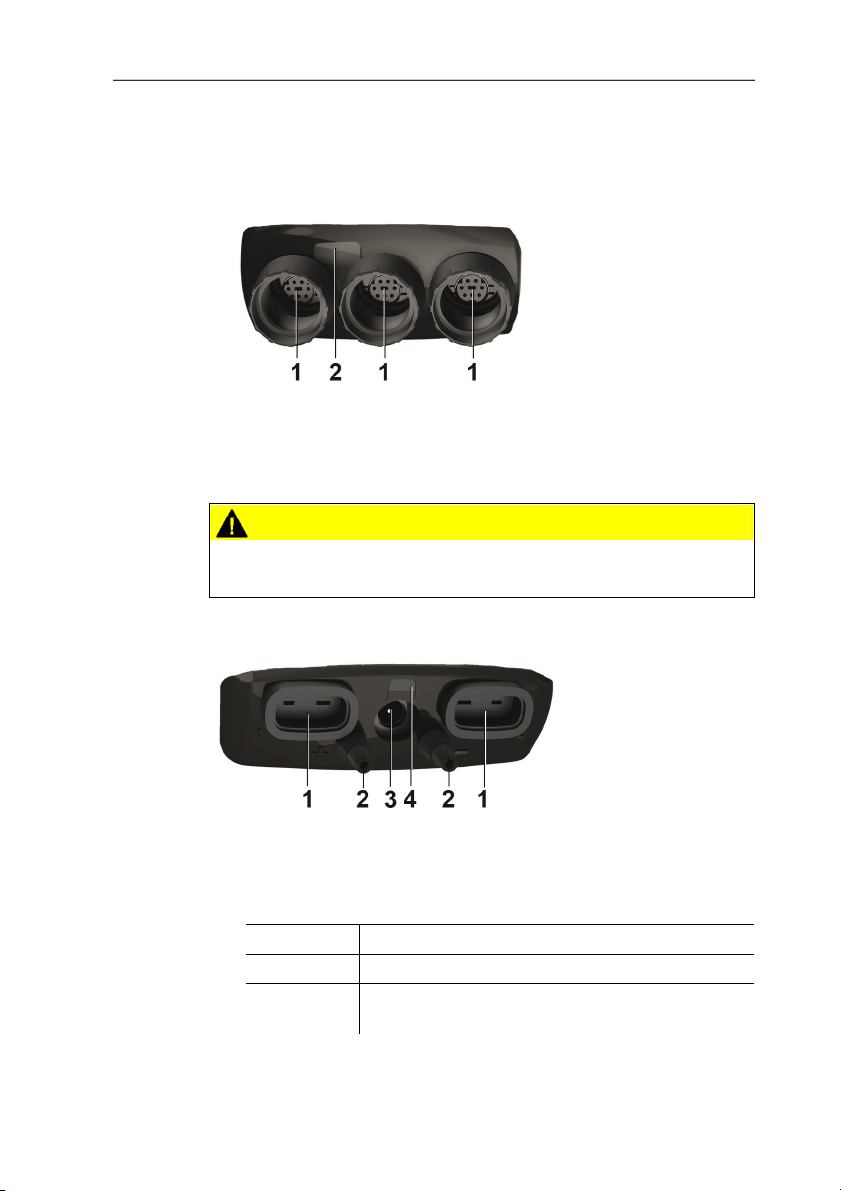
4.1.2. Instrument connections and interfaces
Top
1 Probe sockets for digital probes
2 IR interface for printouts with testo report printer (art. no. 0554
0549)
CAUTION
Risk of injury from infrared beam!
> Do not direct infrared beam at human eyes!
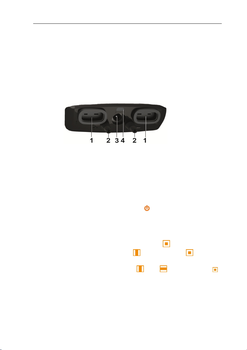
Bottom
12
1 TC connection for temperature probe type K
2 Connections for differential pressure (+/- sign on the instrument)
3 Mains socket
4 Status LED, mains socket
Status Explanation
LED off Rechargeable battery is not charging
LED on,
Rechargeable battery is charging
lights up
Page 13
Status Explanation
LED on,
flashes
slowly
LED on,
flashes
quickly
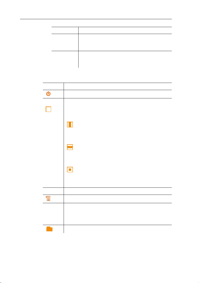
4.1.3. Controls
Button Functions
[]
[]
[Esc]
[]
[–]
[]
4 Product description
Rechargeable battery is not charging,
instrument/battery temperature too high
Rechargeable battery is not charging, battery
faulty
Switch measuring instrument on / off
The following symbols are used to operate the trackpad.
see Navigating in the menu, page 19.
Move your finger on the trackpad to scroll up or down
on the screen.
Move your finger smoothly over the trackpad
[]
from top to bottom: scrolls down.
Move your finger smoothly over the trackpad
from bottom to top: scrolls up.
Move your finger smoothly over the trackpad
[]
from left to right: scrolls right.
Move your finger smoothly over the trackpad
from right to left: scrolls left.
Briefly touch the trackpad with your finger to
[]
confirm the selection. When confirming, you
should notice a click similarly to pressing a
button.
Back, cancel function
Open main menu, save settings
Configurable button for quick access to a frequently
used function. The button is not preassigned at the
factory. Configure button, see Performing settings, page
22.
Explorer is opened, see Explorer menu, page 27.
13
Page 14
4 Product description
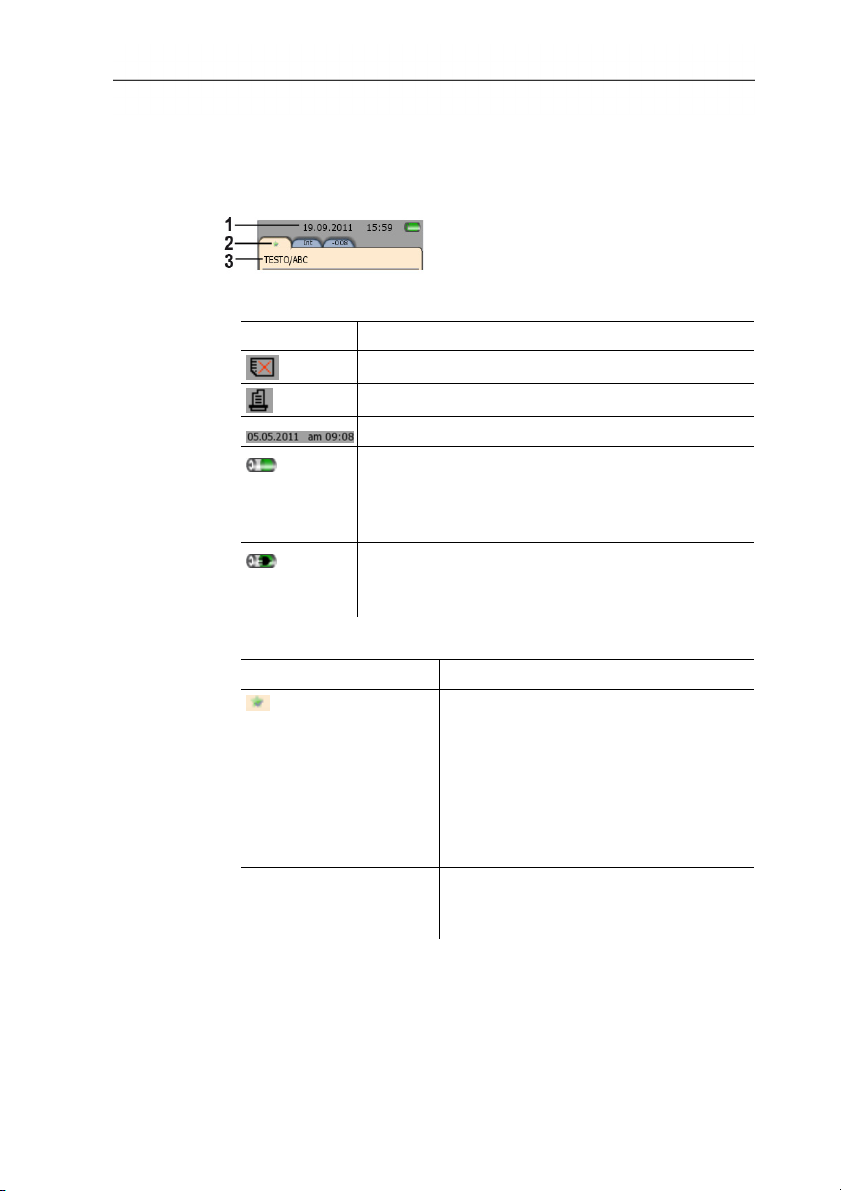
4.1.4. Display
Status line and tabs
1 Status bar (dark grey background):
Icon Explanation
2 Tabs:
Tab name Explanation
(Favourites tab)
Int Measurement values of the internal
There is no SD card in the instrument
Printing
Date and time
Battery operation
Indication of remaining capacity of the rech. batt.
by the colour and fill level of the battery symbol
(green = 5-100%, red = < 5%)
Mains operation
Indication of remaining capacity of rech. batt:
see above
The Favourites tab is the actual work
area for the instrument see Favourites
tab, page 25.
Here, measurement values of various
probes can be combined into one
measurement, and measuring
programs can be run, saved and
printed.
sensors and connected TC probes
are displayed.
14
Page 15
4 Product description
Tab name Explanation
-881 (Example; the last
three digits of the serial
number of the probe
are displayed. The full
serial number of the
probe is shown on a
label on the probe.)
An additional tab is displayed for each
connected probe with the
measurement values of the probe and
the calculated parameters. The tabs
are displayed in the order in which the
probes were connected to the
instrument.
3 Info field of register tabs: display of the selected measuring
location/measuring point. The displayed measuring point can be
selected in Explorer, see Explorer menu, page 27.
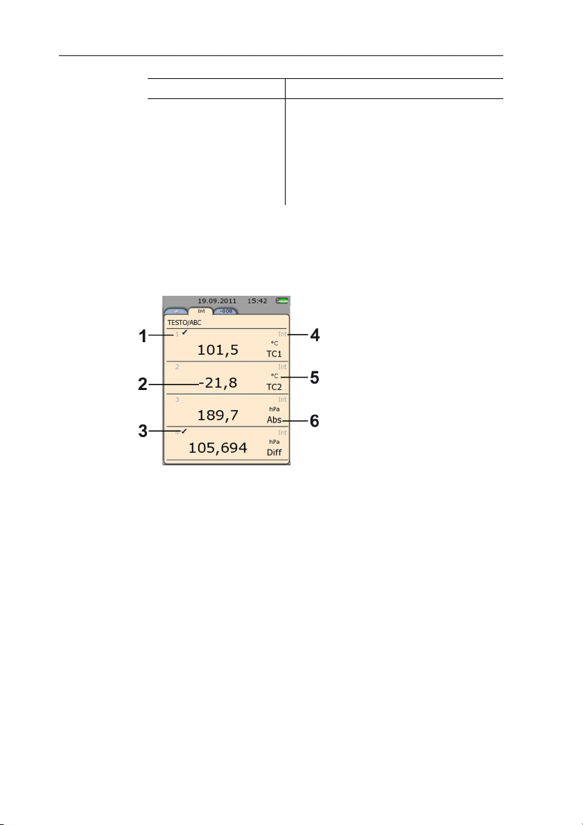
Measuring view
1 Line number
2 Measurement value
3 Indication that the measurement value is also displayed in the
Favourites tab.
4 Probe designation
5 Unit
6 Measurement parameter
The measuring view can be changed individually for each tab, see
Setting the measurement display, page 23.
15
Page 16
5 First steps
5 First steps
5.1. Commissioning
Initial charging of rechargeable battery
The testo 480 is delivered with a partially charged battery. Charge
the battery fully before using it for the first time.
1. Connect the mains unit to the mains socket (3).
2. Connect the mains plug to a power socket.
- Battery charging is started: status LED (4) lights up.
- The battery is fully charged: status LED (4) is off.
3. Disconnect instrument from the mains unit.
- After initial charging of the rech. battery, the instrument is ready
for use.
Switching on
1. Switch the instrument on with [].
- The start screen appears.
For initial commissioning or after a factory reset, the Initial
operation menu is opened automatically. Set the required menu
language:
> Call up the required selection list with [].
2. Select the language with [] and confirm with [].
- Instrument language is changed.
3. Set the date and time with [] and [] and confirm with [].
16
Page 17
5 First steps
4. Select ISO/US units with [] and confirm with [].
The setting only relates to the measured values and can be
individually adjusted for each measurement value if
required.
5. [] → Save and close.
- The current measurement values are displayed. The instrument
is now operational.
Switching off
Unsaved measurement values are lost when the
instrument is switched off.
> Switch the instrument off with [].
Connecting probes / sensors
Probes are detected automatically by the instrument.
Make sure the connections are secure, but do not use force!
> Insert the probe connector into the probe socket:
• Bottom of the instrument: TC probe (type K)
• Top of the instrument: digital probe:
Push/pull plug-in connections protect digital probes from
being unintentionally disconnected from the instrument.
> Connect pressure tubes to + and -.
Caution! Danger of injury caused by the pressure tube
jumping away from the connection socket!
> Ensure correct connection.
17
Page 18
5 First steps
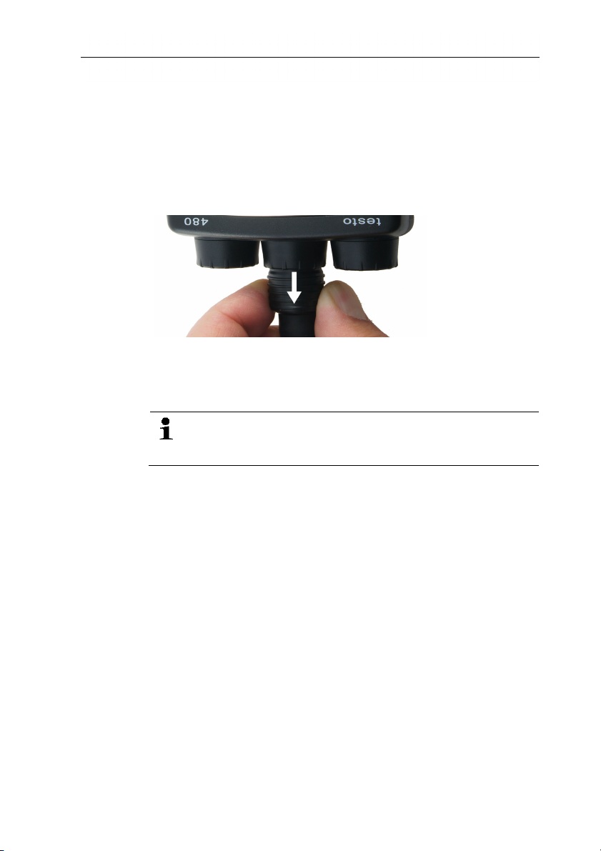
Removing probes
Thermocouple (TC) probe:
> Unplug connector from the socket.
Digital probe:
1. Pull back outer sleeve to release the push/pull plug-in
connection.
2. Unplug connector from the socket.
Connecting the mains unit
If the mains unit is connected, the instrument is powered
automatically via the mains unit.
When power is supplied via the mains unit, the instrument
may heat up. This may increase the measurement
uncertainty during TC measurement.
1. Plug the mains unit instrument connector (art. no. 0554 8808)
into the mains socket on the bottom of the instrument.
2. Plug the mains unit plug into a mains socket.
- The instrument is supplied with power via the mains unit and
battery charging begins automatically.
18
Page 19

5.2. Getting to know the product
5.2.1. Navigating in the menu
1. Press [].
- The Options menu is opened. Selected function is highlighted
white.
2. Select navigation/function:
• [] Move the trackpad down to select the menu item.
• [] Briefly touch the trackpad with your finger to confirm
the selection.
• Press [Esc] to cancel the action and switch to measuring
mode.
5 First steps
Short form
This document uses a short form for describing operating steps
(e.g. calling up a function).
Example: calling up Min/Max
Short form
Steps
required
[] →
1. Open Main
menu: [].
function
Display → Min/Max.
2. Select
Display
4. Select
menu: [].
3. Confirm
5. Confirm
selection: [
].
Min/Max
menu: [].
selection: [
].
19
Page 20

5 First steps
5.2.2. Calling up a function
1. Select function: [].
- A box appears around the selected function.
2. Confirm selection: [].
- The selected function is opened.
5.2.3. Exit the menu
> Press [Esc].
Before the entered data or measurement data may be lost,
a confirmation prompt always appears, which must be
confirmed with [].
Or
5.2.4. Switching to another tab
> [] → Save and close.
> Select the required tab: [].
- Required tab is activated and all other tabs are greyed out.
5.2.5. Entering values
Some functions require values (numbers, units, characters) to be
entered. Depending on the function that is chosen, the values are
entered via either a list field or an input editor.
20
List field
1. Select the value to be changed (numerical value, unit): [], [
] (depending on the selected function).
2. Press [].
3. Set value: [], [] (depending on the selected function).
Page 21

4. Confirm the entry: [].
5. Repeat steps 1 and 4 as required.
6. Save the entry: [] → Save and close.
Input editor
1. Select the value to be changed (character): [], [].
2. Accept value: [].
Options:
> Toggle between upper / lower case characters:
Select
> Toggle between characters and numbers: select or
.
> Insert space: select
.
> Delete character in front of cursor:
select .
3. Repeat steps 1 and 2 as required.
4. Save the entry: select .
5 First steps
5.2.6. Saving values
21
> [] → Save and close.
Page 22

6 Using the product
6 Using the product
6.1. Performing settings
1. Press [].
- The configuration menu is opened.
2. Select Settings and set parameters:
Symbol Explanation
Energy brightness The brightness of the display can be
adapted to suit ambient conditions.
Trackpad It is possible to set the response time of
the trackpad.
Speed-dial keys Functions that are frequently required can
be assigned to one of the two function
keys [–].
Energy
management
It is possible to set the time frame for
automatically switching off the instrument
or the display illumination to preserve the
battery.
Date/time
Password
Various displays can be selected.
When password protection is enabled, all
these functions can only be carried out by
entering the password:
• Instrument factory reset
• Probe reset
• Firmware update
• Change/deactivate password
• Probe name
22
If you forget the password, it can
only be reset by Testo Service
Password protection is not set as default.
Units It is possible to toggle between ISO and
US units. The setting only relates to the
unit of the measured parameters, not to
the calculated parameters.
Page 23

6 Using the product
Symbol Explanation
Norm data The temperature and absolute pressure
values for the internal calculation of the
standard flow rate can be changed.
Factory-set: 25 °C, 1013.25 hPa
Pressure settings Selection of the additional information
that should be included on a
measurement value printout.
Language The instrument language is set. Select a
language that you can understand well.
Factory reset The instrument is reset to the factory
settings:
• Settings
• Adjustment data
• Password deactivated
• Favourites tab is blank
> After a factory reset, switch off the
instrument with [] and then switch it
on again.
3. []→ Save and close.
- Instrument switches to the measuring view.
6.2. Setting the measurement display
The measurement display can be set individually for each probe
tab. These settings are saved in the probe and also apply when the
probe is next connected.
✓ Tab for which the measurement display should be changed is
selected.
1. Press [].
- The configuration menu is opened.
23
2. Select Display function and set parameters:
Adjustable parameters
Representation Explanation
Min/max
When the function is activated, each
line shows: average value, min value and
max value.
To deactivate: select function again.
Page 24

6 Using the product
Representation Explanation
Parameter display The individual lines can be changed in
the parameter display:
• Changing measurement parameters
and units: Select line [].
• Move/delete/insert lines [].
• Copy lines to Favourites tab [].
Lines displayed on the Favourites tab
are indicated with a tick.
Number of lines Selects how many lines should be
displayed at the same time.
If not all lines can be displayed at the
same time, a scrollbar appears on the
right. The remaining lines can be
displayed with [].
- Instrument switches to the selected measuring view.
see Calculated measurement parameters, page 24
6.2.1. Calculated measurement parameters
The following calculated measurement parameters can –
depending on the connected probes – also be included in the
measurement value display for the measured parameters.
24
Operating flow rate
Value calculated from measured air velocity multiplied by the crosssection under the prevailing conditions in the application (e.g.
56 °C, 920 hPa).
Standard flow rate
Value calculated from the operating flow rate relating to the values
entered under norm data (e.g. 25 °C, 1013 hPa).
Dampness degree (pressure-dependent)
Unit g/kg: Describes how many grams of water are contained in a
kg of dry air. It is used to calculate the absolute pressure entered
under norm data.
Water content
Indicates the volume percentage of water vapour in the measured
gas. Unit is not absolute (ppm or %).
Page 25

Dewpoint
Temperature at which condensation of the water vapour in the gas
occurs.
Psychrometer temperature (pressure-dependent)
Wet-bulb temperature of a psychrometer. It is used to calculate the
absolute pressure entered under norm data
Enthalpy
Heat content of the measured gas. Unit kJ/kg or BTU/lb.
Absolute humidity
Describes how many grams of water are contained in a cubic metre
of the currently measured gas. Unit g/m³.
6.3. Favourites tab
The Favourites tab is the actual work area for the instrument.
Here, measurement values of various probes can be combined into
one measurement, and measuring programs can be run, saved and
printed.
Only the measurement values displayed on the Favourites tab are
saved in the measurement protocol.
> [] → Display → Parameter display → [] → Add line to
Favorites.
When the probe is first connected, all measurable parameters are
transferred over to the Favourites tab. Calculated measurement
parameters must be added manually on the Favourites tab.
6 Using the product
Adjusting the displayed measurement parameters
25
> [] → Display → Parameter display → []
Page 26

6 Using the product
6.4. Probe menu
Call up function:
> [] → Probe menu.
Adjustable parameters
Symbol Explanation
Damping (moving
average)
Probe info Probe name, serial number and probe
Probe name
Adjustment info The probe-specific adjustment data saved
Damping type and duration can be
individually adjusted.
Damping can be activated/deactivated.
type are displayed.
Probe name can be edited.
on the probe can be displayed.
The digital probes allow direct
measurement and signal
conversion in the probe. This
technology means that
measurement uncertainty caused
by the instrument is no longer an
issue.
The probe can be calibrated
without a hand instrument.
Entering the adjustment data via
the EasyClimate software
generates a zero-error display.
26
Humidity
adjustment
Humidity adjustment is possible with the
following probes:
• Humidity probe
• IAQ probe
• Thermal air flow measuring head and
humidity probe
When a thermal air flow
measuring head and humidity
probe is used, the probe must be
deactivated before the
adjustment.
Page 27

Symbol Explanation
Probe reset
6.5. Explorer menu
In Explorer, all saved measurement values are displayed with the
assigned data like the measuring program and customer data in a
set structure.
Measurement values that were not saved are lost when the
measuring instrument is switched off!
Calling up the Explorer view
> Press [].
- Explorer structure is displayed.
6 Using the product
Probe is reset to the factory settings:
• Measurement value display
• Probe name
• Adjustment table
• Humidity adjustment
• Damping
Icon Feature
The root folder is a default folder, which
cannot be deleted, moved or renamed.
The folder is used to structure data and is where
all elements (such as folders, measuring
locations, measuring points, etc.) are saved.
27
Selection collapses sub-tree.
Selection expands sub-tree.
Page 28

6 Using the product
Factory-set measuring point under which the
measuring programs are saved if no specific
measuring location is created.
Measuring location documenting the name and
address of the customer. A measuring location
can have several measuring points.
Measuring point (e.g. ventilation shaft 1)
documenting the location description with
measurement-related parameters, e.g. crosssections. A measuring point can have several
measuring programs.
Measuring program documenting the measuring
process and the start and stop criteria for the
measurement (e.g. continuous or punctual
measurement).
Grid measurement (standards-compliant air flow
and volumetric flow rate measurement in
ventilation and air-conditioning systems) see Grid
measurement, page 34.
Turbulence measurement (standards-compliant
measurement of comfort) see Turbulence
measurement, page 38.
Report of the saved measurement data
All settings configured in the Explorer
structure before measurement are stored
in the protocol and cannot be
subsequently changed.
The Explorer structure can also be edited via the
EasyClimate software and re-imported into the instrument.
28
Creating a new folder
A folder is always created in another folder.
1. Select the (root) folder in which the new folder is to be created.
2. [] → New folder.
3. Enter name.
4. Finalise the entry: [] → Save and close.
Page 29

6 Using the product
Other folder options
• [] → New measuring location: create new measuring
location in the selected folder.
• [] → Edit folder: change the name of an existing folder.
• [] → Delete folder: delete an existing folder, including the
locations created therein.
Creating a new location
A location is always created in a folder.
1. Select the folder in which the location is to be created.
2. [] → New measuring location.
3. Enter values.
4. Finalise the entry: [] → Save and close.
Other measuring location options
> [] → New measuring point: create new measuring point in
the selected measuring location.
> [] → Edit measuring location: make changes to an existing
location.
> [] → Delete measuring location: delete an existing
measuring location, including the measuring points created
therein.
Creating a new measuring point
A measuring point is always created under a measuring location.
1. Select the measuring location in which the measuring point is to
be created.
2. [] → New measuring point.
3. Enter values.
4. Finalise the entry: [] → Save and close.
29
Page 30

6 Using the product
Other measuring point options
> [] → Select measuring point: measuring point is selected
> [] → Edit measuring point: make changes to an existing
> [] → Delete measuring point: delete an existing measuring
> [] → New measuring program: determine parameters for a
> [] → New grid measurement: carry out grid measurement,
> [] → New turbulence measurement: carry out turbulence
> [] → New PMV/PPD measurement: Carrying out a
> [] → New WBGT measurement: Carrying out a WBGT
For creating a new measuring program, see PMV/PPD
measurement, page 43.
see WBGT measurement, page 41
see Measuring program, page 31
and displayed in the status line in the measuring view. Reports
are saved under the selected measuring point.
measuring point.
point, including the measurement protocols saved for it.
new individual measurement.
see Grid measurement, page 34.
measurement, see Turbulence measurement, page 38.
PMV/PPD measurement, see PMV/PPD measurement, page
43.
measurement, see WBGT measurement, page 41.
6.6. Measurements & Measuring programs
General measurement information
• Depending on the measurement parameter to be measured,
certain probes must be plugged into the instrument.
• Some (thermal) probes require a warming-up phase until they
are ready to measure.
Adjustment phase
• For some measurement parameters, additional calculation
parameters must be set to ensure correct measurement results,
see Performing settings, page 22
30
Page 31

6 Using the product
6.6.1. Retaining (“holding”) measurement values
Displayed measurement values can be held on the Favourites or
Probe tabs and printed out. The measurement values cannot be
saved in one measurement protocol.
> [] →Hold.
- The measurement value is retained. is displayed.
> Cancel Hold: [] →Hold.
Held measurement values can be printed see Measuring program,
page 31
The measuring values can be saved in one measurement protocol.
6.6.2. Quick back-up
With quick back-up, the current measuring values are saved to the
folder selected for the measurement.
If no measuring point has been selected, the measurement
protocols are saved under "Default Point".
> [] → Quick back-up.
- Measuring values are saved.
see Printing measurement values, page 49
6.6.3. Measuring program
You can customise measuring programs to match the relevant
measuring task (e.g. continuous or punctual measurement). These
measuring programs are linked to a specific measuring point. After
the measurement, the relevant measurement protocols are saved
under the measuring program.
For creating a new measuring program,
A measuring program is always created under a measuring point.
1. Press [].
- Explorer structure is displayed.
2. Select a measuring point for which the measuring program
should be created.
3. [] → New measuring program.
31
Page 32

6 Using the product
4. Determine parameters.
Parameter Explanation
Name Name under which the measuring program is
saved in Explorer.
Measuring point Measuring point to which the measuring
program is assigned.
Measuring type
• Continuous: Mean calculation across a
specific period
• Punctual: Mean calculation across
individual current values buffered via []
or button on probe handle.
• Continuous/Punctual: At each point a
mean value is calculated according to the
end criterion set (Duration or Number of
values). At the end of the measurement,
an overall mean value is calculated.
Measuring rate Interval at which the measurement values are
recorded.
Start criterion
• Manual: Measurement is triggered via [
].
• Date/Time: Measurement starts at a set
time.
End criterion
• Manual: Measurement is ended via []
→ End.
• Date/Time: Measurement ends at a set
time.
• Duration: measurement ends after a set
duration has lapsed.
• Number of values: measurement ends
after a sequence of measured values.
The measuring program only applies to the Favourites tab.
Only the values displayed on the Favourites tab are saved
in the measurement protocol.
32
Page 33

6 Using the product
5. Save setting and navigate to the measuring program: select [
] → Save and start measurement.
> If you do not want the measurement to start immediately: select
[] → Save and close.
Another way to create a measuring program in the
Favourites tab under the selected measuring point:
> [] → Application → Measuring program.
Starting a measuring program
If a start date has been set, the program starts
automatically. In the case of a manual start, the
measurement must be triggered as described.
1. Select required measuring program.
2. [] → Start measuring program.
> Depending on the selected start criterion, the measurement
must be started via [].
Other measuring program options
> [] → Edit measuring program: make changes to an existing
measuring program.
> [] → Delete measuring program: delete an existing
33
measuring program.
Page 34

6 Using the product
6.6.4. Grid measurement
There are various options for measuring the air and volumetric flow
rate in ventilation and air-conditioning systems. These are
distinguishable by the measuring range in particular. For the testo
480, there are three different flow probes:
• Thermal probes (incl. temperature measurement and possibly
humidity measurement) for low flow speeds
• 16 mm wheel measuring head (incl. temperature measurement)
for average flow velocities
• Pitot tube for measurements at high velocities and in heavily
contaminated flows with a high percentage of particles
Detailed background information on grid measurement and
carrying it out can be found in the Testo Ambient Air
Measurement for Practical Users field guide. You can
request a free copy or download it from www.testo.com.
Selecting a suitable measuring point
The main prerequisite for accurate measurement is the suitability of
the measuring point. Minimum distances from points of
discontinuity must be observed:
• From points of discontinuity upstream of the flow, observe a
clearance of at least six times the hydraulic diameter Dh = 4A/U
(A: channel cross-section, U: channel circumference).
• From points of discontinuity downstream of the flow, observe a
clearance of at least twice the hydraulic diameter Dh = 4A/U (A:
channel cross-section, U: channel circumference).
34
Preparing for measurement
✓ 16 mm wheel measuring head, thermal air flow measuring head
and humidity probe or Pitot tube is connected.
1. Switch the instrument on.
2. Create a new measuring point in Explorer under the required
measuring location.
3. Set the following parameters:
Page 35

6 Using the product
Parameter Values
Temperature,
Relative humidity
and Absolute
pressure
The parameters must be correctly entered or
measured. This affects the measurement
with Pitot tube.
Thermal probe has an internal absolute
pressure sensor. No entry is required here.
Flow rate
correction factor
Pitot factor
Must be 1.00 (has a proportional effect on
the flow rate).
Only has to be entered for measurement with
Pitot tube, see Pitot tube measurement, page
39.
Channel geometry
Profile and dimensions of the channel. Select
channel geometry with []:
Electric power
Manual input value, only used for logging.
4. In Explorer, under the created measuring point, create a new
grid measurement, see Explorer menu, page 27.
5. Make the following settings to suit the measuring point:
Parameter Values
Measuring type
Punctual or Continuous/Punctual
The end criterion can be defined individually
depending on the selection.
Nominal
volumetric flow
Information value for the nominal volumetric
flow. The unit can be freely selected, this
value appears in the protocol and on the
printout as supplementary information.
Probe
Select probe via serial number with [].
If a Pitot tube is connected, the
differential pressure is measured
when INT is selected.
Layout Measuring
points
The number of measuring points depends on
the distance from the point of discontinuity
and irregularities in the profile. More
information can be found in the Testo
"Ambient Air Measurement for Practical
Users" field guide.
35
Page 36

6 Using the product
Parameter Values
Measuring type
Nominal
volumetric flow
Hole position
Edge spacing
Uncertainties
Channel
Uncertainties
Density (air
density, only for
Pitot tube
measurement)
6. Save setting and navigate to the measuring program: select [
> If you do not want the measurement to start immediately: select
Punctual or Continuous/Punctual
The end criterion can be defined individually
depending on the selection.
Information value for the nominal volumetric
flow. The unit can be freely selected, this
value appears in the protocol and on the
printout as supplementary information.
Select any hole position with [] depending
on channel accessibility.
For example, damping of the channel wall
can be taken into consideration. Entered
values influence the coordination of the
measuring points.
Estimated uncertainty of the channel
dimensions. Entered value is taken into
account in the flow rate calculation.
When all relevant measurement parameters
(temperature, relative humidity, absolute
pressure) are measured, the value can be set
to 0.
] → Save and start measurement.
[] → Save and close.
36
Page 37

6 Using the product
Performing the measurement
✓ All points under "Preparing for measurement" have been carried
out.
1. Position the probe at the grid measurement point shown in the
form of a chart on the display.
2. With [] or the integrated measurement button on the probe,
transfer the measured value, or start the continuous/punctual
measurement.
- The measured point is indicated with a tick.
- The position of the measuring point is automatically moved to
the next point on the display and the new immersion depth
required is displayed. The immersion depth of the probe can be
found on the scale of the probe shaft.
3. Repeat steps 1 and 2 until all points have been measured.
- The individual velocity measurement values are used to
calculate the mean flow velocity, from which the volumetric air
flow is then calculated.
If high differences in flow velocities are ascertained over
the cross-section, the number of measuring points is to be
increased.
The number of measuring points is then adequate if the
measurement value for each area is representative for its
immediate surroundings, i.e. if it can be regarded as a
genuine mean value for its portion of the area.
37
Page 38

6 Using the product
4. Before the measurement is completed, any measured point can
> Select [] → Save and close.
- Measurement protocol is saved in Explorer under the selected
The HVAC protocol contains multiple views, which can be changed
via[].
• Values Result: End result (mean value) and deviation of the
• Graphic Result: Channel view with the results per measuring
• HVAC program parameters: preset parameters for the
• Density parameters: preset values for calculating the density
be approached. If this point needs to be remeasured → []→
Repeat measurement.
As soon as all measuring points have been input,
"Measurement completed" is displayed. The whole
measurement can be repeated → []→ Repeat HVAC
measurement.
measuring point.
flow velocity and volumetric flow parameters.
point.
measurement (e.g. channel geometry).
(temperature, humidity, absolute pressure).
6.6.5. Turbulence measurement
A connected turbulence probe 0628 0143 enables the turbulence to
be calculated for the flow value in accordance with DIN EN 13779.
The turbulence probe 0628 0143 has an internal absolute pressure
sensor used to carry out automatic compensation. There is no need
to enter an absolute pressure value here.
✓ Turbulence probe 0628 0143 is connected.
1. Press [].
- Explorer structure is displayed.
2. Select the desired measuring point.
3. [] → New turbulence measurement.
- Turbulence calculation window is opened.
4. Start measurement: [].
- Turbulence determination is started. It takes 180 sec., but can
also be ended early.
- When measurement is completed: turbulence is displayed in %,
calculated according the formula:
38
Page 39

and draught rating as per EN ISO 7730 is displayed.
5. [] → Save and close.
- Measurement protocol is saved under the selected measuring
point.
6.6.6. Pitot tube measurement
To measure flow with a Pitot tube, the following parameters must
be entered in the measuring point (manual entry or measured
values).
• Temperature
• Relative humidity
• Absolute pressure
6 Using the product
These three paramet
These three parameters are taken into account in the calculation of
the flow.
The Pitot factor for Pitot tubes is generally the same and must be
entered:
• Pitot tubes from Testo 1.00
• Straight Pitot tubes, Pitot factor: 0.67
For Pitot tubes from other manufacturers, the Pitot factor can be
found in the instruction manual or you should ask your supplier.
For carrying out the measurement, see Measuring program, page
31 or see Grid measurement, page 34.
39
Page 40

6 Using the product
6.6.7. Measurement with the funnel
A flow rate funnel is required to determine the flow rate at
ventilation systems. The funnel set (art. no. 0563 4170) comprises
a funnel for measuring at poppet valves (200 x 200 mm) and a
funnel for measuring at fans (330 x 330 mm). The opening of the
funnel should cover the grille completely and tightly.
1. Secure the 100 mm wheel measuring head in the funnel
handle.
2. Connect 100 mm wheel measuring head to the instrument.
3. Switch the instrument on.
The following parameters must be entered for the funnel
measurement in the measuring point, as they influence the
measurement result:
• Flow rate correction factor: value 1.00
• Channel geometry (dimensions of the funnel used)
The input variables for the testovent 410/415 can be found
in the funnel instruction manual or on the funnel label.
For the testovent 417 funnel set, use the following
information (deviates from the information on the funnel):
Ø 8,5cm.
For carrying out the measurement, see Measuring program, page
31.
6.6.8. Pressure measurement
The testo 480 has an internal absolute and differential pressure
sensor. The pressure measurement values are therefore displayed
on the Int tab.
1. Connect pressure tubes for differential pressure measurement
(2) to + and -.
40
Caution! Danger of injury caused by the pressure tube
jumping away from the connection socket!
> Ensure correct connection.
2. Switch the instrument on with [].
Page 41

6 Using the product
3. Position the instrument ready for measurement and stabilise.
The parameter display depends on the position of the
pressure sensor.
4. Zero parameter display: []→ Zero.
- Current pressure measurement value appears on the Int tab in
the set unit.
> Change pressure unit in the parameter display: []→
Display→ Parameter display→ []→ Select measurement
parameter from list → []→[]→ Save and close.
If the measurement values fluctuate widely, it is advisable to damp
the measurement values. Damping is activated in the probe menu
see Probe menu, page 26.
6.6.9. CO2 measurement
• The CO2 probe measures the absolute pressure. The displayed
CO
value is compensated automatically in line with the
2
absolute pressure.
• Due to the sensor, the probe has a relatively high power
consumption. For continuous measurements, use a mains unit
for the power supply.
• To avoid the effects of the CO
probe as far away from your body as possible.
• If sudden changes occur in the concentration, the probe will
require approx. 30 - 60 sec. to adapt to the environment. Gently
waving the probe reduces the adjustment period.
content of respired air, hold the
2
6.6.10. WBGT measurement
Measurement program available as of firmware version
1.05.
Make sure that the specific instrument and cable
temperatures are not exceeded. Extension cables should
be used for high radiation temperatures in particular.
With the WBGT set, the WBGT (Wet Bulb Globe Temperature)
climate index is determined as per DIN 33403 or ISO 7243. The
WBGT index is used to determine the maximum permissible
exposure time at workplaces exposed to heat (e.g. steel industry,
foundries, glass industry or blast furnaces).
41
Page 42

6 Using the product
To calculate the WBGT, 3 different temperatures must be
measured:
• Radiation temperature T
• Ambient temperature T
• Wet bulb temperature T
The calculation is carried out with the following formulas:
WBGT = 0.7 x T
WBGTS = 0.7 x T
Preparing for measurement
✓ Globe thermometer, wet bulb temperature and air temperature
1. Switch the instrument on.
Selecting a suitable measuring point
Performing a measurement
✓ All points under "Preparing for measurement" have been carried
(globe thermometer)
g
a
(temperature of a naturally ventilated
nw
psychrometer)
+ 0.3 x Tg
nw
+ 0.2 x Tg + 0.1 x Ta
nw
probes are connected and mounted on a tripod.
The settings in the measuring point have no effects on the
measurement result.
out.
42
1. Press [].
- Explorer structure is displayed.
2. Select the desired measuring point.
3. [] → New WBGT measurement.
- WBGT measurement is opened.
4. Select ID numbers of the individual probes.
5. Select measuring type and measuring rate.
6. Set criteria for start and end of the measurement.
7. [] → Save and start measurement
During the measurement, the values are calculated from
the current measuring values.
After the measurement, a calculation is carried out based
on mean values.
8. [] → Save and close
- Measurement protocol is saved under the selected measuring
point.
Page 43

6.6.11. PMV/PPD measurement
Measurement program available as of firmware version
1.05.
The PMV/PPD measurement determines the comfort level (PMV =
Predicted Mean Vote) and the relative discomfort (PPD = Predicted
Percentage Dissatisfied) e.g. at workstations and is described in
the ISO 7730.
The mean radiation temperature required for determining
PMV/PPD is calculated in the testo 480 from the measurement
parameters of globe temperature, ambient temperature and air
speed. The formula is based on forced convection and applies to
standard bulbs with 150 mm diameter.
Necessary measuring values
• Mean radiation temperature in °C = t
• Globe temperature in °C = t
• Ambient temperature in °C = t
• Air speed in
m
/s = va
tr = [(tg+273)4+2.5*108*va0.6*(tg-ta)]1/4-273
Factors to be entered
• Clothing
Clothing reduces body heat losses and is therefore classified
based on its insulating value.
The insulating effect of clothing is given in the unit clo or m²
°K/W (1 clo = 0.155 m² °K/W).
The clo value can be calculated by adding together the values
of the individual items of clothing.
Insulating values for individual items of clothing can be found in
ISO 7730.
Alternatively, a clo range can be selected.
6 Using the product
2
r
g
a
2
Only with positive pressures
43
Page 44

6 Using the product
• Activity
Input parameters for clothing
Parameter
in clo
0 – 0.02 No clothing
0.03 – 0.29 0.005 – 0.045 Underwear
0.30 – 0.49 0.046 – 0.077 Shorts and T-shirt
0.50 – 0.79 0.078 – 0.122 Trousers and T-shirt
0.80 – 1.29 0.123 – 0.200 Light business wear
1.30 – 1.79 0.201 – 0.277 Warm business wear
1.80 – 2.29 0.278 – 0.355 Jacket or coat
2.30 – 2.79 0.356 – 0.432 Warm winter clothing
2.80 – 3.00 0.433 – 0.465 Extremely warm winter clothing
The metabolic rate gives the energy released by oxidation
processes in the human body, and depends on muscle activity.
The metabolic rate is given in met or W/m2 (1 met = 58.2 W/m²
body surface area). The average adult has a body surface area
of 1.7 m². In a state of thermal comfort, a person with a
metabolic rate of 1 met has heat loss of approx. 100 W.
When calculating the metabolic rate, a mean value of the
activity of the relevant person affected within the past hour must
be used. Met values for various activities can also be found in
ISO 7730.
Parameter in
m2K/W
Explanation
44
Input parameters for activity
Parameter
in met
0.1 – 0.7 6 – 45 Lying down, relaxed
0.8 – 0.9 46 – 57 Sitting down, relaxed
1.0 – 1.1 58 – 59 Seated activity
1.2 – 1.5 70 – 92 Standing up
1.6 – 1.7 93 – 104 Standing up, light activity
1.8 – 1.9 105 – 115 Standing up, moderate activity
Parameter in
W/m2
Explanation
Page 45

6 Using the product
Parameter
in met
Parameter in
W/m2
Explanation
2.0 – 2.3 116 – 139 Slow walking
2.4 – 2.9 140 – 174 Quick walking
3.0 – 3.4 175 – 203 Strenuous activity
3.5 – 4.0 204 - 233 Extremely strenuous activity
The factors to be entered refer to the ISO 7730 Appendix B
and C.
We recommend using the following probes:
• Globe thermometer (0602 0743)
• Humidity probe (0636 9743)
• Comfort probe (0628 0143)
• Tripod (0554 0743)
Preparing for measurement
✓ Globe thermometer, wet bulb temperature and air temperature
probes are connected and mounted on a tripod.
1. Switch the instrument on.
Performing a measurement
✓ All points under "Preparing for measurement" have been carried
out.
1. Press [].
- Explorer structure is displayed.
2. Select the desired measuring point.
3. [] → New PPMV/PPD measurement.
- PMV/PPD measurement is opened.
4. Select ID numbers of the individual probes.
5. Specify parameters and unit for clothing and activity.
6. Select measuring type and measuring rate.
45
Page 46

6 Using the product
7. Set criteria for start and end of the measurement.
8. [] → Save and start measurement
9. [] → Save and close
- Measurement protocol is saved under the selected measuring
10. The measurement protocol is displayed.
11. [] → Graphic
Graphical representation
1 PPD axis, scale from 0% to 100%
2 PMV axis, scale from -3 to +3
3 Green area of curve from -0.5 to 0.5 PMV
4 Calculated point from PPD and PMV.
5 Critical area of curve
During the measurement, the values are calculated from the
current measuring values.
After the measurement, a calculation is carried out based
on mean values.
point.
46
Formula for display
PPD = 100-95*exp(-0.03353*PMV
4
– 0.2179*PMV2)
Page 47

6.6.12. Saving measurement values
All measurement protocols displayed in Explorer are saved in the
internal instrument memory.
Saving measurement values on an SD card
6 Using the product
1. Insert SD card.
Only SD cards with max. 2 GB space can be used.
2. Select root folder in the Explorer view.
3. [] → Export.
- An export message is displayed.
47
Page 48

6 Using the product
Importing measurement values from an SD card
When importing data from an SD card, all data in the
internal instrument memory is overwritten.
48
1. Insert SD card.
Only SD cards with max. 2 GB space can be used.
2. Select root folder in the Explorer view.
3. [] → Import.
- A list of importable data is displayed.
4. Select the required entry.
- An import message is displayed.
Page 49

6.6.13. Printing measurement values
Selection of the additional information that should be
included on a measurement value printout, see Performing
settings, page 22.
From measuring mode
✓ testo printer (0554 0549) has been switched on.
✓ Required tab has been selected.
1. Align IR interfaces testo 480 and testo printer.
2. Select [] → Print.
- The set measuring view and are displayed.
- Printout of the currently displayed measurement values is
produced.
From the instrument memory
✓ testo printer (0554 0549) has been switched on.
1. Press [].
2. Navigate to the saved measuring protocol.
3. Select [] → Open measurement protocol.
- Measurement data view is opened.
4. Align IR interfaces testo 480 and testo printer.
5. Select [] → Print.
- The printout is generated.
The saved measurement protocols can also be displayed
via the testo EasyClimate software.
6 Using the product
6.6.14. Display measuring values graphically
Measuring values of max. four measurement parameters can be
displayed as a colour graphic over a period of 110 seconds. In the
case of longer time frames, the oldest values are deleted and
replaced by the new ones. The graphic mode is purely a display
mode, i.e. the measuring values cannot be stored.
Selection of the displayed measurement parameters is based on
the display sequence in measuring mode.
• First measurement parameter displayed: red
• Second measurement parameter displayed: green
49
Page 50

6 Using the product
• Third measurement parameter displayed: blue
• Fourth measurement parameter displayed: violet
1. Select the required tab.
> If necessary change the order of the measurement parameters,
2. [] → Graphic mode.
- Graphic mode is activated .
> Exit graphic mode: [] → Graphic mode or [ESC].
as only the first four measurement parameters are displayed.
The values are deleted when switching tabs, however
graphic mode is not terminated. On returning to the tab, the
measurement starts again in graphic mode.
If the values are to be retained after switching tabs, [] →
select Hold .
50
1 Displayed measuring values
2 Graphically displayed measuring value
3 Average, minimum and maximum values since graphic mode
selection
4 Vertical scaling marking (5 seconds)
5 Specific x-axis of the respective measurement parameter in the
same colour as the graphically displayed measuring value
Page 51

6.6.15. Transferring measurement values
To view and evaluate the measurement results on the PC,
you need the testo EasyClimate software.
1. Switch on the testo 480.
2. Connect the instrument to the PC with a mini USB cable.
- Instrument is identified by the PC as a USB mass storage
device. The operating system automatically assigns the
instrument memory a drive letter. This is displayed in Windows
Explorer.
When the instrument is connected to the PC, the
instrument control keys are locked. As soon as the
instrument is disconnected from the PC, it can be operated
again via the control keys.
3. For carrying out an instrument readout via testo EasyClimate
software and processing data, see separate testo EasyClimate
software instrument manual.
6 Using the product
51
Page 52

7 Maintaining the product
7 Maintaining the product
Cleaning the instrument
> If the housing of the instrument is dirty, clean it with a damp
cloth.
Do not use any aggressive cleaning agents or solvents! Weak
household cleaning agents and soap suds may be used.
7.1.1. Battery care
> Charge new rechargeable battery fully before commissioning.
> If possible, always discharge the rechargeable battery and
recharge it fully.
> At low ambient temperatures, the rechargeable battery running
time decreases. This reduces the available useful life.
> Do not store the rechargeable battery for long periods when
discharged. (The best storage conditions are at 50-80 % charge
level and 10-20 °C ambient temperature; charge fully before
using again).
> The rechargeable battery life depends on the storage, operating
and ambient conditions. The available useful life of the
rechargeable battery reduces more and more with frequent use.
If the useful life is significantly shortened, the rechargeable
battery should be replaced.
7.1.2. Carrying out humidity adjustment
In humidity calibration, the measurement parameter of the
connected probe is adjusted to the reference value at the two
standard adjustment points 11.3 % RH and 75.3 % RH and the
deviations between the measuring value and the nominal value are
minimised across the entire measuring range.
The Testo adjustment set provides a reference value to calculate
the offset for a humidity adjustment.
Humidity adjustment is possible with the following probes:
• Humidity probe
• IAQ probe
52
• Thermal air flow measuring head and humidity probe
When a thermal air flow measuring head and humidity
probe is used, the probe must be deactivated before the
adjustment ([] → Switch off flow probe). The probe can
only then be exposed to the reference conditions.
Page 53

7 Maintaining the product
✓ Instrument is switched on and probe is connected.
✓ Probe is already exposed to reference conditions (e.g. salt pot)
for an adequate adjustment time.
• Adjustment time for humidity probe at least 30 min
• Adjustment time for IAQ probe at least 1 h
• Adjustment time for thermal air flow measuring head and
humidity probe at least 3 h
✓ Tab for the relevant probe is activated.
1. [] → Probe menu.
2. Select reference value used (11.3%RH/75.3%RH).
3. [] → Adjustment.
- A pop-up window with the remaining adjustment time is
displayed.
4. [] → End.
- Adjustment menu is closed.
5. Carry out adjustment for the second adjustment point.
53
Page 54

7 Maintaining the product
7.1.3. Carrying out a firmware update
Updated firmware can be installed on the instrument.
A firmware update can also be carried out with testo
EasyClimate.
✓ Instrument is switched on.
1. Download the current firmware file from
www.testo.com/download-center (registration required).
2. Unzip downloaded zip file.
3. Connect the instrument to the PC with a mini USB cable.
- Instrument is identified by the PC as a USB mass storage
device. The operating system automatically assigns the
instrument memory a drive letter. This is displayed in Windows
Explorer.
When the instrument is connected to the PC, the
instrument control buttons are locked. As soon as the
instrument is disconnected from the PC, it can be operated
again via the control buttons.
4. Copy unzipped firmware file and res folder to Update folder.
5. Log out instrument from Windows (safely remove hardware).
6. Unplug USB cable.
7. Switch the instrument off.
8. Switch the instrument on.
- Firmware has been updated.
54
Page 55

8 Tips and assistance
8.1. Questions and answers
Question Possible causes / solution
flashes Rechargeable battery is low.
> Switch to mains operation.
-+++- lights up instead of
the measurement
parameter display
The value is above the permissible
measuring range.
> Keep to the permissible measuring
range.
+---+ lights up instead of
the measurement
parameter display
The value is below the permissible
measuring range.
> Keep to the permissible measuring
range.
- - - - lights up instead of
the measurement
parameter display
Data cannot be copied to
the SD card or imported
from the SD card.
Instrument no longer
responds when a button is
pressed.
Instrument sensor is faulty.
> Contact your dealer or the Testo
Customer Service.
SD card is write-protected.
> Cancel write protection (small
slider control on the SD card).
Internal error has occurred.
1. Hold down [] for >10 sec.
- The instrument is switched off.
2. Switch instrument on with [].
If we could not answer your question, please contact your dealer or
Testo Customer Service. For contact data, see back of this
document or website www.testo.com/service-contact.
8 Tips and assistance
55
Page 56

8 Tips and assistance
8.2. Accessories and spare parts
Description Article no.
System case for comfort level measurement 0516 4801
System case for grid measurements 0516 4800
Tripod for workplace evaluation with holders
for hand instrument and probe; can also be
used as probe extension, e.g. for 100 mm
probe
Connection hose, silicone-free, 5 m, load to
max. 700 hPa
Connection hose, silicone, 5 m, load to max.
700 hPa
Funnel set comprising funnel for disc valves
(Ø 200 mm) and funnel for fans (330 x
330 mm) for supply and exhaust air
Testovent 410, flow rate funnel, Ø
340 mm/330 x 330 mm, incl. case
Testovent 415, flow rate funnel, Ø
210 mm/190 x 190 mm, incl. case
Testo high speed printer with wireless
infrared interface, 1 roll of thermal paper and
4 AA batteries
For a complete list of all accessories and spare parts, please refer
to the product catalogues and brochures or look up our website
www.testo.com
0554 0743
0554 0453
0554 0440
0563 4170
0554 0410
0554 0415
0554 0549
56
Page 57

8 Tips and assistance
57
Page 58

0970 4800 en 04 V01.05 en-GB
 Loading...