

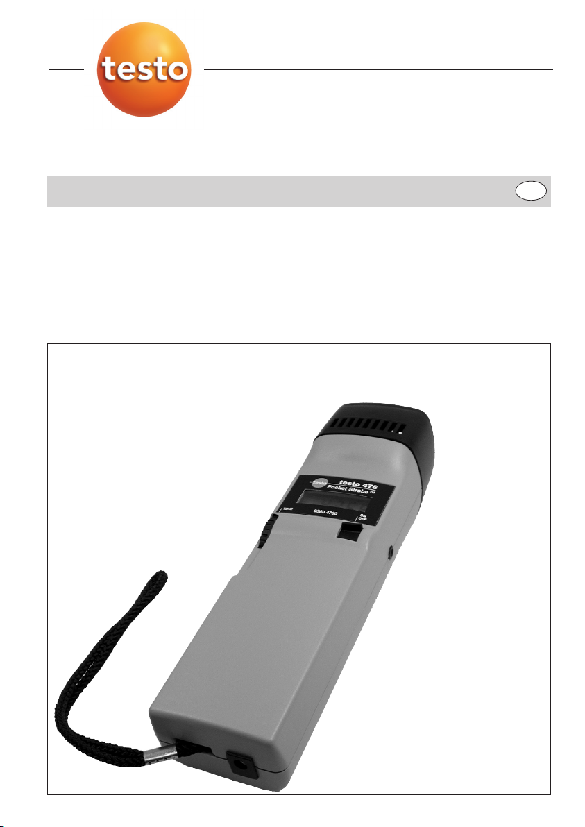
testo 476
Instruction manual
en

Preface
2
Foreword
Dear Testo customer,
Congratulations on choosing a Testo product. We hope
that you will enjoy many years of using the product and
that it will help you in your work.
If problems should occur which you cannot rectify
yourself, please consult our service department or your
dealer. We will endeavour to provide fast and competent
assistance to save you long periods out of operation.
Copyright
This documentation is subject to the copyright of Testo AG.
Reproduction and employment contrary to the justified
interests of Testo AG are prohibited without the prior, written consent of the company.
We reserve the right to modify technical details from the
descriptions, specifications and illustrations contained in
this documentation.
Testo AG
Postfach 11 40
79849 Lenzkirch
Germany

General Information
3
This instruction manual contains important information about the features and use of the
instrument. Please read this document carefully and familiarise yourself with the operation of
the instrument before putting it to use. Always keep this manual close at hand in order to
look up necessary information.
Standards/Tests
The conformity certificate confirms that this product fulfills the guidelines in accordance with 2004/108/EEC.

Contents
4
Preface ..........................................................2
General Information ......................................2
Contents ........................................................4
1. Basic safety instructions ..............................5
2. Intended use ..................................................6
3. Delivery range ................................................6
4. Overview ........................................................7
5. Power supply ................................................8
5.1 Mains unit Setup ............................................8
5.2 Charge the battery ..........................................9
5.3 Battery management ....................................10
6. Operation......................................................10
7. Error messages............................................11
8. External triggering ......................................11
9. Replacing the flash tube ............................12
10. Application information ..............................13
10.1 Slowing down motion ..................................13
10.2 Apparent direction of movement ..................14
10.3. Harmonics ....................................................14
10.4 Determing an object’s true RPM ..................15
11. Maintenance ................................................18
12. Accessories / Spare parts ............................18
13. Technical data..............................................19
1. Basic safety instructions
5
WARNING:
Stroboscopes give the illusion of stopped motion. Do
not touch the machine or object being observed!
The use of stroboscopes may induce an epileptic seizure in those persons predisposed to this type of attack.
Explosion hazard. Do not use this product in the
presence of an explosive environment.
CAUTION:
Do not use this product in wet or condensating
environments.
Do not allow liquids or metallic objects to enter into the
ventilation holes.
Recharge the battery using only the original mains unit
with supplied the
testo 476.
Use the supplied mains unit only with the
testo 476.
DANGER HIGH VOLTAGE!
To reduce risk of an electronic shock, do not open the
Pocket-Strobe. To replace the flash tube, refer to chapter 9. Replacing the flash tube.
There are no user-serviceable parts inside.

2. Intended use
6
You can use the testo 476 in a variety of industrial, laboratory, R&D and academic environments.
Most commonly, the
testo 476 is used to make objects
which are moving at high speeds appear to be moving in
slow motion. When this occurs, you can then safely and
easily analyse their motion, check for proper registration,
determine sources of unwanted vibration, etc.
Also, you can use the
testo 476 to apparently “freeze” an
object’s movement. Without making contact, you can
accurately measure the object’s rotational speed or reciprocation rate.
Unlike other portable stroboscopes, the
testo 476
(XENON-)stroboscope takes only one hand to operate.
Typical applications include use with:
- High speed assembly lines, conveyor systems,
bottling operations, etc.
- Printing presses and cloth looms
- Motors, fans, pumps and turbines
- Calibration and inspection equipment
- Monitoring laboratory & research applications
Your testo 476 hand-held stroboscope comes with the following items:
-
testo 476 Stroboscope
- Universal mains unit (100...240V AC)
and 4 adapters specific to country
- External Trigger Jack
- Carrying Case
- Instruction Manual
3. Delivery range

4. Overview
7
On/Off
Flash Adjustment Knob adjusts the flash rate. The
speed with which the flash rate changes is controlled by
how quickly the knob is rotated:
Quick rotation = flash rate changes in large
increments.
Slow rotation = flash rate changes in small
increments.
LCD display shows flash rate (flashes per minute =
FPM).
Low Bat indicator will light up when the battery needs
charging.
Power supply socket (incl. battery charging)
The External Trigger Jack is used when employing an
external sensor to control the flash rate.
EXT illuminates when External Trigger Jack is plugged.
Lanyard can be looped on a belt or used as a wrist
strap.
Front Bezel Screw is removed in order to replace the
flash tube.
Underside:
Close-up of LCD:

8
5. Power supply
5.1 Mains unit Setup
When first using the mains unit, select the appropriate plug
connector for use in the AC power outlet (several styles
provided). Align the holes in the rear side of the plug connector (
) with the pins in the receptacle in the mains unit
body (
) and push. When properly seated, you will hear a
click and the plug connector will not move. The charger is
now ready for use.
Change the Plug Connector
To remove the connector from the mains unit, slide the
switch on the mains unit (
) up and the connector will pop
out. To insert a different plug connector follow the procedures described in Battery Charger Setup.
5.2 Charge the battery
Charge the battery before first use or when the “LOW BAT“
indicator appears on the LCD.
NOTE:
When the “LOW BAT” indicator is shown, the
testo 476 has
approximately 6 minutes of operating time remaining. When
the “LOW BAT” indicator flashes on and off, the battery is
empty and the
testo 476 will automatically switch off.
Before first use, you must set up the battery charger. Refer
to 5.1 Battery Charger Setup.
1 Insert the barrel plug end of the mains unit into the
power supply socket on the
testo 476.
Plug the mains unit into a mains socket.
2 The red light on the mains unit will illuminate continuous-
ly while the battery is charging.
- The instrument will recharge in about five hours.

9
5. Power supply
5.3 Battery management
Several factors effect the battery life:
- The warmer the operating environment, the shorter the
battery life; the cooler the environment, the longer the
battery life.
To maximise the life of the battery:
Keep the battery not fully charged.
Keep storage temperature as low as possible (10...20
°C)

6. Operation
10
The testo 476 can be operated with and without mains
unit. The Lithium ion rechargeable battery is recharged
when the instrument is connected to the mains unit.
1 Aim the testo 476 at the moving object and turn it on
(
).
- There will be a delay of 1-2 seconds before the flash
begins to operate.
- If the LOW BAT symbol in the display is illuminated,
charge the battery.
2 Adjust the flash rate by rotating the Flash Adjustment
Knob (
) until the object appears motionless (as you
approach the movement frequency, the image appears
to move more slowly).
- This value will be shown in the LCD display ().
Unit: „Flashes per minute“ = 1/min = RPM.
To get the unit „Flashes per seconds“ = 1/s = Hz:
Divide the shown value by 60.
IMPORTANT:
Motionless images do not only appear when the movement
frequency is reached, but also when multiples and fractions
of the movement frequency are reached.
For additional information on visually slowing down the
motion of an object as well as using your
testo 476 as a
tachometer, please refer to the appropriate section(s) later
in this manual.
Helpful Hints:
The flash frequency for which the image of the object
appears with the greatest contrast is the movement frequency.

7. Error messages
11
E1: Front bezel is not fastened correctly. If the E1 messa-
ge appears, the instrument must be switched off.
Remove the front bezel screw, reseat the reflector
and tighten the front bezel screw (
).
Underside:
8. External triggering
The testo 476 can be externally triggered.
The EXTERNAL TRIGGER jack is DTL/ TTL compatible. It
detects a square-wave signal of 0 to +5 volts which is at
least 800nsec in duration.
The EXTERNAL TRIGGER jack uses a standard 1/8” phono
plug (max. cable length 3m, shielded cable is recommended) with the configuration shown below (only valid for
supplied plug!):
The outer connection (barrel) is common.
The middle connection provides an unregulated direct
voltage output (6 - 7.5 VDC, R
i
= 100 W) to drive exter-
nal sensors which are not self-powered.
The center connection is the input signal, which triggers
the flash.
NOTES:
Turn the Pocket-Strobe off when inserting or removing a
trigger cable.
Whenever an external trigger is used, the Flash
Adjustment Knob is disabled.
WARNING:
Do not trigger the device with signals over 208 Hz.
EXT illuminates when External
Trigger Jack is plugged.

12
9. Replacing the flash tube
1 Remove the front bezel screw located on the underside
of the front bezel (
).
2 Swing the bezel upwards and outward carefully (
). Be
sure not to break the old flash tube. Ensure that the
bezel hooks on the top edge are released. Remove the
bezel.
3 Firmly grasp the spent flash tube and pull it straight out
(
).
4 Using a lint and oil-free tissue, insert a new flash tube ,
with the marking pointing up, (
) into the socket.
CAUTION:
Make sure that the flash tube is correctly
installed in the socket. If it is crooked, the
light output of the reflector is reduced.
5 Slide the front bezel (
) over the new tube and rehinge
it at the top. Rotate the bezel back towards the bottom
of the case and reinsert the front bezel screw.
NOTE:
As a safety precaution, the unit will not flash unless the
bezel is in place. If the bezel is not secured properly, an
emergency message “E1” will be shown in the display.
Refer to 7. Error messages for additional information.

13
10. Application information
10.1 Slowing down motion
As discussed, the primary use of the Pocket-Strobe is to
slow down or “freeze” the apparent motion of moving
objects. This allows you to analyse their run-time performances safely and easily.
To make an object appear to move in slow motion, you
need to strobe it at a rate slightly above or slightly below its
actual speed (or any harmonic of its speed as discussed
below). Simply use the COARSE/FINE ADJUSTMENT knob
until you achieve the desired apparent movement.
Helpful Hints:
The speed at which the object appears to move can be
determined by subtracting the flash rate from the object’s
actual rate.
Example:
If an object is rotating at 1,000 RPM and you strobe it at a
rate of 1,005 flashes per minute (FPM), the object will
appear to be moving at a rate of 5 RPM.
Speed = Actual Rate - Flash Rate
= 1,000 PRM - 1,005 PRM
= 5 RPM

10. Application information
14
10.2 Apparent direction of movement
The direction (clockwise vs. counterclockwise or forward
vs. backward) at which the object appears to move is
determined by the flash rate, the object’s actual direction of
movement and the orientation of the stroboscopic beam to
the object.
Example:
Assume you wish to visibly slow down the movement of a
fan which is rotating clockwise at 1,000 RPM.
Case 1: If you stand in front of it and strobe it at a rate of
1,005 flashes per minute (FPM), the object will appear to
be moving at a rate of 5 RPM in a counterclockwise direction.
Case 2: If you stand in front of it and strobe it at a rate of
995 FPM, it will appear to move at a rate of 5 RPM in a
clockwise direction.
Case 3: If you stand behind it and strobe it at a rate of
1,005 FPM, it will appear to move in a clockwise direction
at a rate of 5 RPM.
Case 4: If you stand behind it and strobe it at a rate of
995 FPM, it will appear to move in a counterclockwise
direction at a rate of 5 RPM.
10.3. Harmonics
If you continuously increase the flash rate while strobing an
object, it may appear to freeze, slow down, speed up, go
forward, freeze again, go backwards, form multiple images,
etc. These images appear at mathematically determined
multiples or harmonics of the object’s actual speed.
Example:
Assume you wish to slow the motion of the fan used in the
last example, but you want it to be brighter.
Technique: Starting from 1,000 FPM, slowly increase the
flash rate. At 1,500 FPM the image will appear to freeze
again. Continue to increase the rate.

10. Application information
15
The image will appear to freeze again at 3,000 FPM. At this
rate, the fan appears to be very bright. You can now use
the FINE ADJUSTMENT knob to vary the rate above and
below 3,000 to make the fan appear to move both clokkwise and counterclockwise.
Helpful Hints:
- Harmonic images appear at both whole number multiples as well as fractional intervals of the object’s actual
rate.
For example, a fan rotating at 1,000 RPM will appear to
be frozen at the whole number multiples of 2,000 (2x),
3,000 (3x), 4,000 (4x) etc., as well as at the
fractional rates of 500 (1/2x), 750 (3/4x) and 1,500
(1 1/2x), etc.
- Some of the harmonic images are “singular” in appearance while others are “multiple”. This becomes important if you want to determine the objects actual rate as
discussed in chapter 10.4 Determing an object’s true
RPM.
10.4 Determing an object’s true RPM
The Pocket-Strobe can be used as a digital tachometer to
determine the true RPM and / or the reciprocation rate of an
object. This is done by visually “freezing” the object’s
movement and then reading the LCD display. As with all
stroboscopes, it is important to verify that this frozen image
is not a harmonic of the object’s actual rate.
Helpful Hints:
- Knowing the approximate rate of the object in advance
gives you a useful starting point.
- If the object has a uniform shape, like a multi-blade fan
or motor shaft, you must give it an identifying mark
(using paint or reflective tape or equivalent) in order to
differentiate its orientation.
- A single image always appears if the rotational speed
set on the instrument matches the rotational speed of
the object or if an integer divisor (1/2, 1/3, ...) of the
object speed has been set on the instrument.

10. Application information
16
Example 1 (mark needed):
This example shows why identifying marks are important.
Suppose you want to determine the true RPM of this fan.
The only thing you know is that its speed is less than 3,500
RPM. If you slowly decrease the flash rate starting from
3,500 FPM, the following “frozen” images appear:
Image No.: 1 2 3 4
Flash Rate: 3,300 2,200 1,650 1,320
Image No.: 5 6 7 8
Flash Rate: 1100 825 733.3 550
What is the actual rate of the fan? Images 1, 3, 5, 6 and 8
are all “frozen,” so the rate could be taken as 3,300, 1,650,
1,100, 825 and 550. Which is correct?
In order to determine the fan’s actual speed, a mark is
added to one of the blades and the test is run again.
Image No.: 1 2 3 4
Flash Rate: 3,300 2,200 1,650 1,320
Image No.: 5 6 7 8
Flash Rate: 1,100 825 733.3 550

10. Application information
17
Using the orientation mark, it is now clear that the images
appearing at 3,300, 1,650 and 825 RPM are multipleimage harmonics. In each of these cases, three identification marks appear. On the other hand, a singular image
appears at 1,100 and again at 550.
The first single image with only one reflection mark appears
if 1.100 rpm has been set on the instrument, another one
at 550. Please remember, a single image always appears if
the rotational speed set on the instrument matches the
rotational speed of the object or if an integer divisor (1/2,
1/3, ...) of the object speed has been set on the instrument. The true rotational speed therefore is 1.100 rpm. If
the instrument is set to 550 rpm, only every second rotor
revolution will be flashed.
Example 2 (no mark needed):
This example illustrates how the actual speed of an object
can be determined without the use of an orientation mark provided that the object has a suitable shape.
Assume that the speed of this cam is known only to be
less than 7,000 RPM. Because it has a unique shape, it
does not need an identifying mark. As the flash rate is
lowered from 7,000, the following harmonic images appear:
Image No.: 1 2 3 4
Flash Rate: 6,000 4,000 3,000 1,500
The harmonic images at 6,000 and 4,000 RPM are not singular, but double and quadruple. A singular image does
appear at 3,000 and again at 1,500 RPM. 3.000 rpm is the
actual rotational speed.

11. Maintenance
18
Due to the high voltage contained within the testo 476, the
user should not attempt to repair the device (exception:
Replacing the flash tube, see p. 12).
If your
testo 476 needs repair, please contact the nearest
Testo service point.
Clean the external surfaces with a dry, lint free cloth only.
Do not allow any liquids to enter into the instrument.
12. Accessories / Spare parts
Name Part no.
Belt bag with clip for hand-held stroboscope 0516 4760
Spare xenon flash lamp for hand-held stroboscope 0213 0020
High light intensity
ISO calibration certificate/rpm 0520 0012
Optical and mechanical rpm measuring instruments;
cal. points 500; 1000; 3000 rpm

13. Technical data
19
Display Parameters
Range 30...12,500FPM (flashes per minute)
Accuracy ±0.01% from Display ±1 digit
Resolution ±1 FPM
Repeatability ±1 FPM
Display 5 Digit LCD
Flash Tube Parameter
Longevity 200,000,000 flashes at 6000 FPM (approx. 550 hours)
Flash Duration < 9µs
Light Emission 1200 Lux measured at 20cm / 8” approx. from target
Flash Colour 6.000...6.500K
Flash Energy max. 170mJ
Electrical Specification
Use Battery and mains operation
Continuous Usage Time >2 h at 1.500 FPM on 23°C / 73°F
External Trigger Input 0...5V DTL/TTL compatible 3.5 mm / 1/8”
standard connector Uout = 7.2V unregulated direct voltage
output (6 - 7.5 VDC, Ri= 100 W)
Line Power Input for recharging 100...240V, 50/60Hz; incl. 4 area connector pins
Battery Lithium ion battery block
Recharging Time max. 3.5h
Overload protection / yes
trickle charge
Housing
Material ABS
Dimensions 240 x 65 x 40mm / 9,75 x 2,75 x 1,75inch
Weight 465g
Ambient Conditions
Ambient Temp. 0°...40°C (32°...114°F)
Storage Temp. -25°C...70°C (-10°F...125°F)
Humidity max. 95% not condensed
Warranty 2 years, warranty conditions see website www.testo.com/warranty

testo AG
Postfach 11 40, 79849 Lenzkirch
Testo-Straße 1, 79853 Lenzkirch
Telefon: (07653) 681-0
Fax: (07653) 681-100
E-Mail: info@testo.de
Internet: http://www.testo.com
0970 4761 en 02
 Loading...