

Page 1
testo
testo 454
Data logger
Instruction Manual
testo
454
Logger
testo
0
1
2
3
4
5
6
7
8
9
•
Aus
Off
Ein
On
Enter /
10...14V DC
TESTO
QUALITY
I
S
O
9
0
0
1
c
e
r
t
i
f
i
e
d
Page 2

testo
Contents
1 Applications. . . . . . . . . . . . . . . . . . . . . . . . . . . . . . . . . . . . . . . 3
2 Description of instrument. . . . . . . . . . . . . . . . . . . . . . . . . . . . 4
3 Warning . . . . . . . . . . . . . . . . . . . . . . . . . . . . . . . . . . . . . . . . . 5
4 Keyboard layout . . . . . . . . . . . . . . . . . . . . . . . . . . . . . . . . . . . 6
4.1 Hot keys. . . . . . . . . . . . . . . . . . . . . . . . . . . . . . . . . . . . . . . . 7
5 Menu overview. . . . . . . . . . . . . . . . . . . . . . . . . . . . . . . . . . . . . 8
6 Introductory training
6.1 Measuring . . . . . . . . . . . . . . . . . . . . . . . . . . . . . . . . . . . . . 10
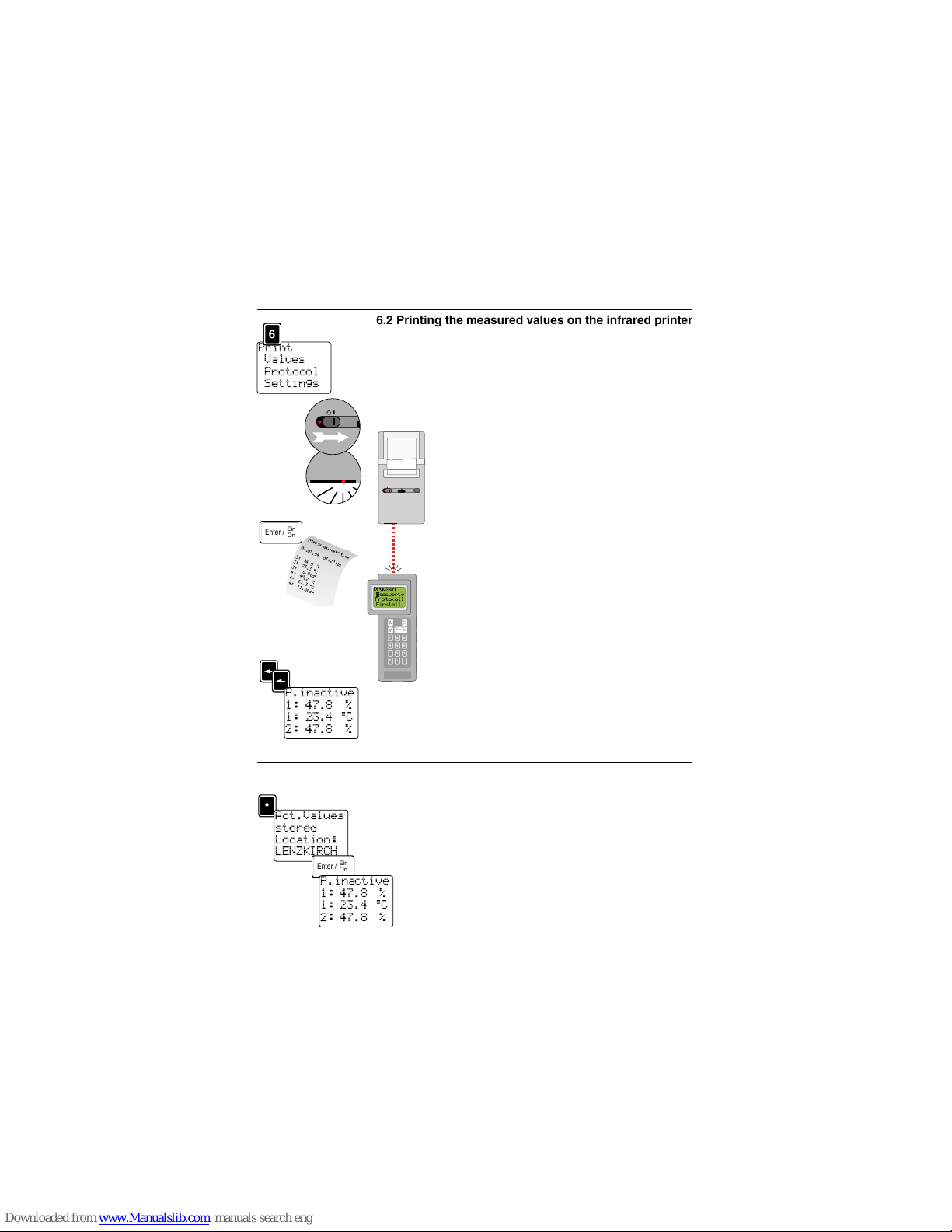
6.2 Printing the measured values on the infrared printer . . . . . 11
6.3 Saving measured values . . . . . . . . . . . . . . . . . . . . . . . . . . 11
6.4 Setting up a location . . . . . . . . . . . . . . . . . . . . . . . . . . . . . 12
7 Operating instructions
7.1 Measuring . . . . . . . . . . . . . . . . . . . . . . . . . . . . . . . . . . . . . 14
8 Main menu
8.1 Averaging. . . . . . . . . . . . . . . . . . . . . . . . . . . . . . . . . . . 15
8.2 Mean value configuration. . . . . . . . . . . . . . . . . . . . . . . 15
8.3 Memory
8.3.1 View . . . . . . . . . . . . . . . . . . . . . . . . . . . . . . . . . . . . . . . 16
8.3.2 State. . . . . . . . . . . . . . . . . . . . . . . . . . . . . . . . . . . . . . . 16
8.3.3 Programs 1 - 3
8.3.3.1 Starting criterium . . . . . . . . . . . . . . . . . . . . . . . . . . 18
8.3.3.2 Rate . . . . . . . . . . . . . . . . . . . . . . . . . . . . . . . . . . . . 20
8.3.3.3 Activating duration and program. . . . . . . . . . . . . . . 21
8.3.3.4 Overview of the programming system . . . . . . . . . . 22
8.3.4 Minimimum rate . . . . . . . . . . . . . . . . . . . . . . . . . . . . . . 22
8.3.5 Keylock. . . . . . . . . . . . . . . . . . . . . . . . . . . . . . . . . . . . . 23
8.3.6 Reset . . . . . . . . . . . . . . . . . . . . . . . . . . . . . . . . . . . . . . 23
8.4 Print . . . . . . . . . . . . . . . . . . . . . . . . . . . . . . . . . . . . . . . . 23
8.5 Location
8.5.1 Select . . . . . . . . . . . . . . . . . . . . . . . . . . . . . . . . . . . . . . 24
8.5.2 Enter. . . . . . . . . . . . . . . . . . . . . . . . . . . . . . . . . . . . . . . 24
8.5.3 Erase . . . . . . . . . . . . . . . . . . . . . . . . . . . . . . . . . . . . . . 24
8.6 Device
8.6.1 Display . . . . . . . . . . . . . . . . . . . . . . . . . . . . . . . . . . . . . 24
8.6.2 Date/Time. . . . . . . . . . . . . . . . . . . . . . . . . . . . . . . . . . . 25
8.6.3 Rechargeable battery. . . . . . . . . . . . . . . . . . . . . . . . . . 25
8.6.3.1 Notes on battery operation. . . . . . . . . . . . . . . . . . . . . . 25
8.6.3.2 Examples for rechargeable battery lifetime . . . . . . . . . 25
8.6.4 Auto-Off . . . . . . . . . . . . . . . . . . . . . . . . . . . . . . . . . . . . 26
8.6.5 Intermediate rate . . . . . . . . . . . . . . . . . . . . . . . . . . . . . 26
8.6.6 Alarm . . . . . . . . . . . . . . . . . . . . . . . . . . . . . . . . . . . . . . 27
8.6.7 Units. . . . . . . . . . . . . . . . . . . . . . . . . . . . . . . . . . . . . . . 28
8.7 Probes
8.7.1 Unit. . . . . . . . . . . . . . . . . . . . . . . . . . . . . . . . . . . . . . . . 29
8.7.2 Scaling . . . . . . . . . . . . . . . . . . . . . . . . . . . . . . . . . . . . . 29
8.7.3 Calibrate. . . . . . . . . . . . . . . . . . . . . . . . . . . . . . . . . . . . 29
8.7.4 Adjust . . . . . . . . . . . . . . . . . . . . . . . . . . . . . . . . . . . . . . 30
8.7.5 Discard. . . . . . . . . . . . . . . . . . . . . . . . . . . . . . . . . . . . . 30
8.8 Specials
8.8.1 Display . . . . . . . . . . . . . . . . . . . . . . . . . . . . . . . . . . . . . 31
8.8.2 Flow volume. . . . . . . . . . . . . . . . . . . . . . . . . . . . . . . . . 31
8.8.3 Density . . . . . . . . . . . . . . . . . . . . . . . . . . . . . . . . . . . . . 31
8.8.4 Pressure. . . . . . . . . . . . . . . . . . . . . . . . . . . . . . . . . . . . 31
2
Page 3

testo 454 -The handy measuring instrument
Nearly all of the probes from the Testo range can be connected to the universal hand-held
instrument. The automatic probe recognition function facilitates quick control measurements. In air conditioning technology several parameters can be quickly measured on
location e.g. temperature, humidity, velocity and pressure. The probe designs are fully
adapted to the respective applications.
testo 454 - The powerful data logger
All of the boundary conditions for an independent long-term measurement are programmable: start of measurement, end of measurement, location name and alarm outputs are
determined by selectable starting criteria. The six freely assignable channels and three
measuring programs make the data logger very versatile. There are various additional special functions available for air conditioning and ventilation technology: averaging, volume
flow display, Pitot tube calculation etc.
testo 454 - Independent application
The rechargeable, environment friendly rechargeable battery makes the user independent
of the power supply. Power can also be supplied from a car battery.
testo 454 - User-friendly operation
The housing is ergonomic and ideal for practical operation and is made of robust ABS.
The large, illuminated display can be easily read and can display three different parameters. The menu-driven user operation via the sealed keyboard makes the instrument easy
to use.
testo 454 - Configuring and data processing on the PC
If a PC and the Comfort software are connected you can take full advantage of the benefits
offered by the data logger. All of the settings in the data logger are prepared first in the PC
and are then loaded into the data logger. Only the measurement is started on the measuring location. The processing of saved measured in the PC is just as uncomplicated as configuring.
Contents
9 Error messages . . . . . . . . . . . . . . . . . . . . . . . . . . . . . . . . . . . 32
10 Technical data
10.1 Measuring instrument . . . . . . . . . . . . . . . . . . . . . . . . . . . . 34
10.2 Infrared printer . . . . . . . . . . . . . . . . . . . . . . . . . . . . . . . . . . 35
10.3 Comfort software - 454 module . . . . . . . . . . . . . . . . . . . . . 35
10.4 Probes . . . . . . . . . . . . . . . . . . . . . . . . . . . . . . . . . . . . . . . . 36
10.4.1 Connection cables for probes . . . . . . . . . . . . . . . . . . . . . . 40
11 Ordering data. . . . . . . . . . . . . . . . . . . . . . . . . . . . . . . . . . . . . 41
12 Warranty conditions . . . . . . . . . . . . . . . . . . . . . . . . . . . . . . . 43
Probe description - Measuring technology. . . . . . . . . . . . . Appendix
1Applications
3
Page 4
testo
2Description of instrument
4
testo
454
Logger
testo
0
1
2
3
4
5
6
7
8
9
•
Aus
Off
Ein
On
Enter /
10...14V DC
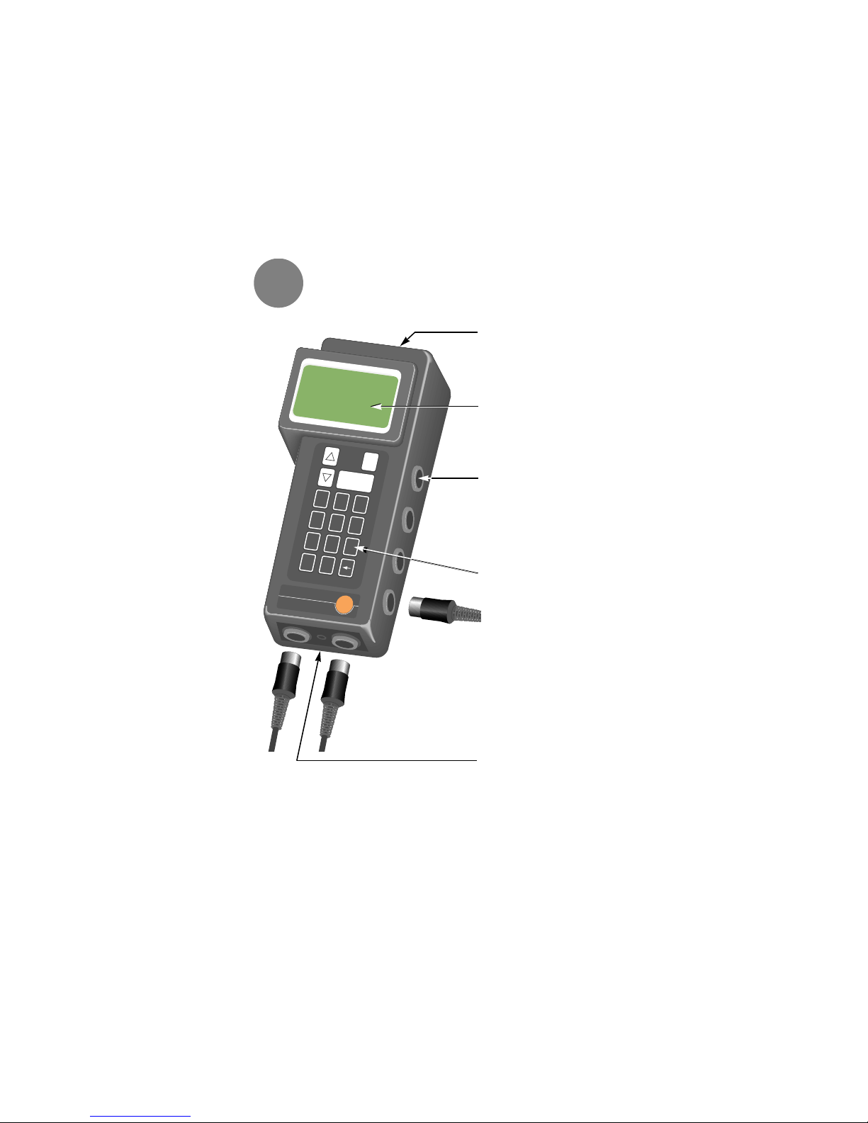
Top of housing
with protective cover for PC interface and alarm/trigger interface.
Display with 4 lines.
6 probe inputs
Assignment is freely selectable,
the instrument recognises the
probes connected by way of a
special code. See label on the
back for socket assignment.
Keyboard
The keyboard commands are
described in the Chapter “Keyboard layout”.
Mains connection
Measuring instrument conforms with
EN 50 082-1 / EN 55 011 Group 1 Class A
Page 5
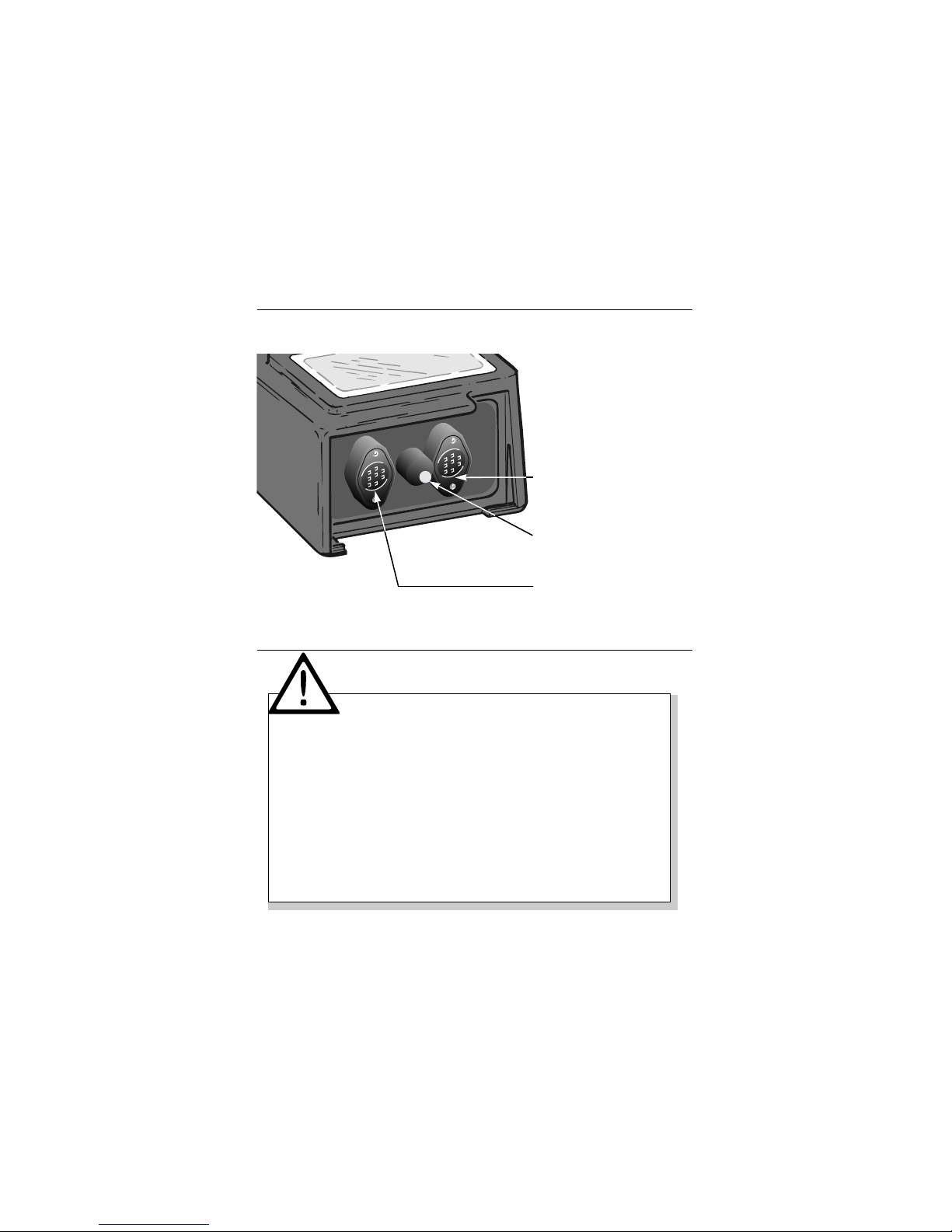
RS/232 Trigger/Alarm
2Description of instrument
5
Trigger/alarm connection for
alarm/ trigger connection cable
0554.0012
Infrared diode for transferring
data to the infrared printer. The
cover does not need to be
removed before printing.
RS/232 interface for connection
to the PC.
3
Warning
Please read before using instrument
Do not measure on live parts.
Observe permissible storage and transport temperatures and the permissible oper-
ating temperature (e.g. protect measuring instrument from direct sunlight)!
Switch off the instrument when changing the configuration (e.g. probe change, plug-
ging in the V24 cable) because the values specific to the probes can only be read
after the instrument is switched on.
If the instrument is opened, improperly handled or force is used the warranty rights
are cancelled.
In the case of temperature probes which come into contact with metal, there may
be an electric discharge caused by the different potential between metal and the
surface probe. Please apply adhesive tape to the point of measurement during
this type of application. In this way a discharge which could limit the functioning
of the instrument is preventde.
Page 6
testo
4Keyboard layout
6
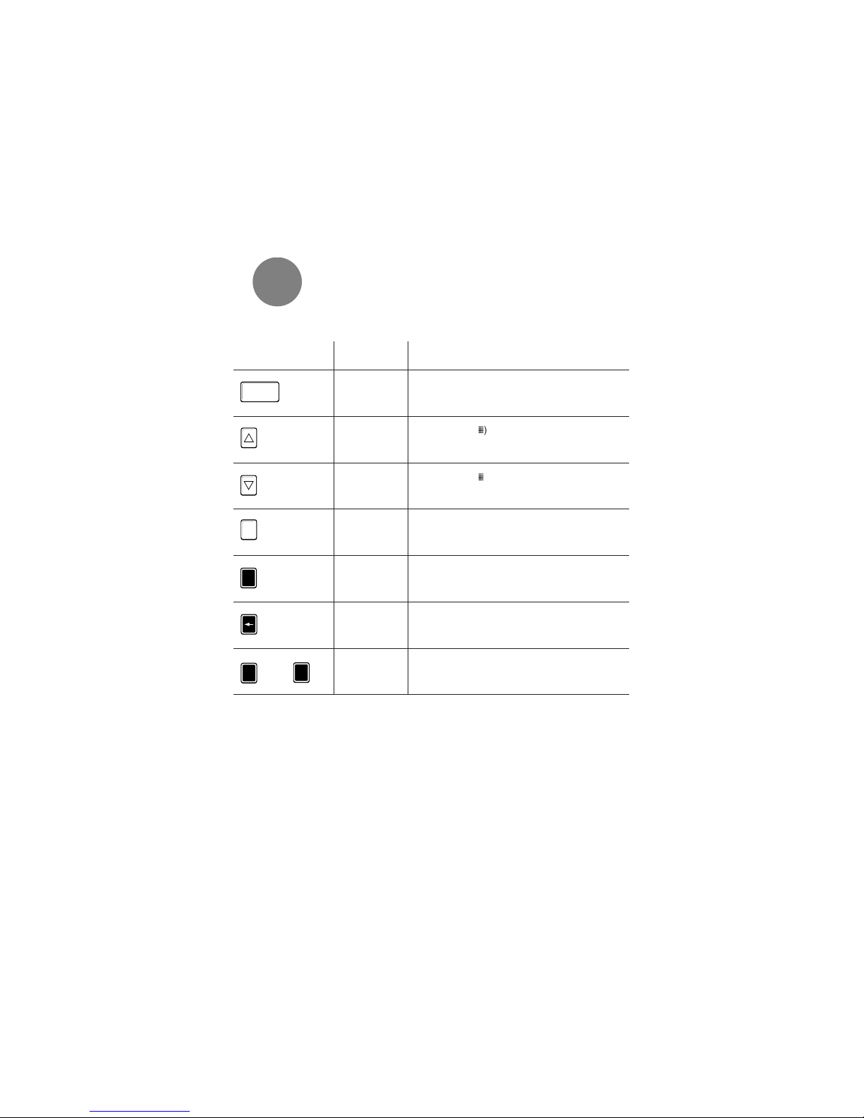
Text Function
<Enter> Switches on instrument
Opens selected menu
Confirm entry
<Up> Moves cursor (˛) upward in the display
Scrolls display
Selects letters
<Down> Moves cursor (˛) downward in the display
Scrolls display
Selects letters
<Off> Switches off instrument
<Point> Decimal point
Hot key function
<Arrow> ESC key
Returns to a higher level
Inquiry on the hot key function (in the meas. menu)
<0>…<9> Enters numbers
Hot key function
Ein
On
Enter /
Aus
Off
•
0
9
…
Key
Page 7
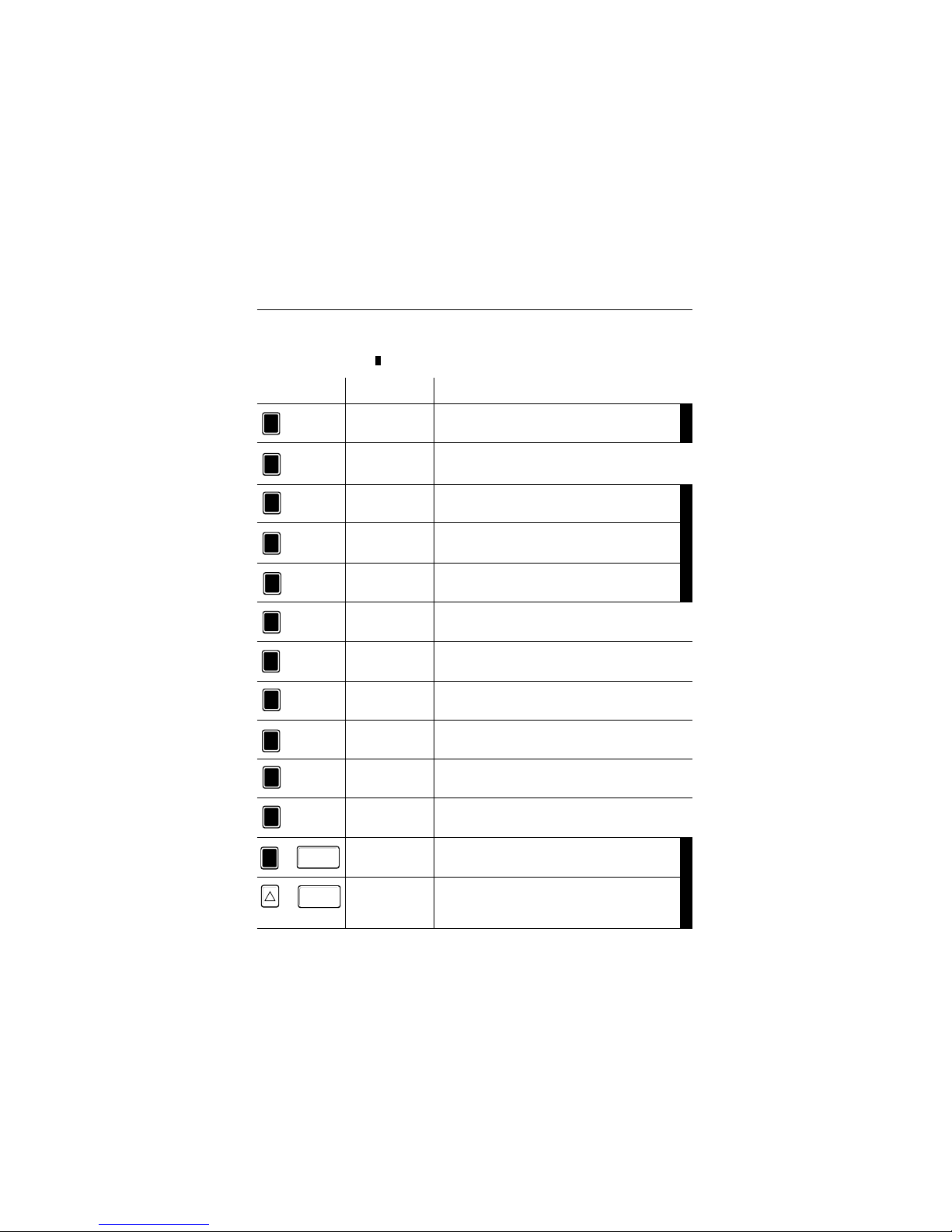
Key Text Text in display
Function when key is pressed
4Keyboard layout
7
Backl. (Backlight)
Background light on/off
P1 I/O
Start/stop programming 1
P2 I/O
Start/stop programming 2
P3 I/O
Start/stop programming 3
Location
Selects from list
View
Activates protocol overview
Print
Activates print menu
P1 set
Defines programming 1
P2 Set
Defines programming 2
P3 Set
Defines programming 3
Pkt.Msg (Point measurement)
Files single measuring blocks in the memory.
0
1
2
3
4
5
6
7
8
9
•
<Point>
<0>
<1>
<2>
<3>
<4>
<5>
<6>
<7>
<8>
<9>
Displays version number
•
<Point>+<Enter>
“Zeroizes” pressure probe
Ein
On
Enter /
Ein
On
Enter /
<Up>+<Enter>
Hot key functions are short commands which make it possible to activate submenus directly without having to select them by scrolling through the menu tree. The hot key functions,
marked with black bars ( ), are only active parallel to the measuring menu.
+
+
4.1 Hot keys
Page 8
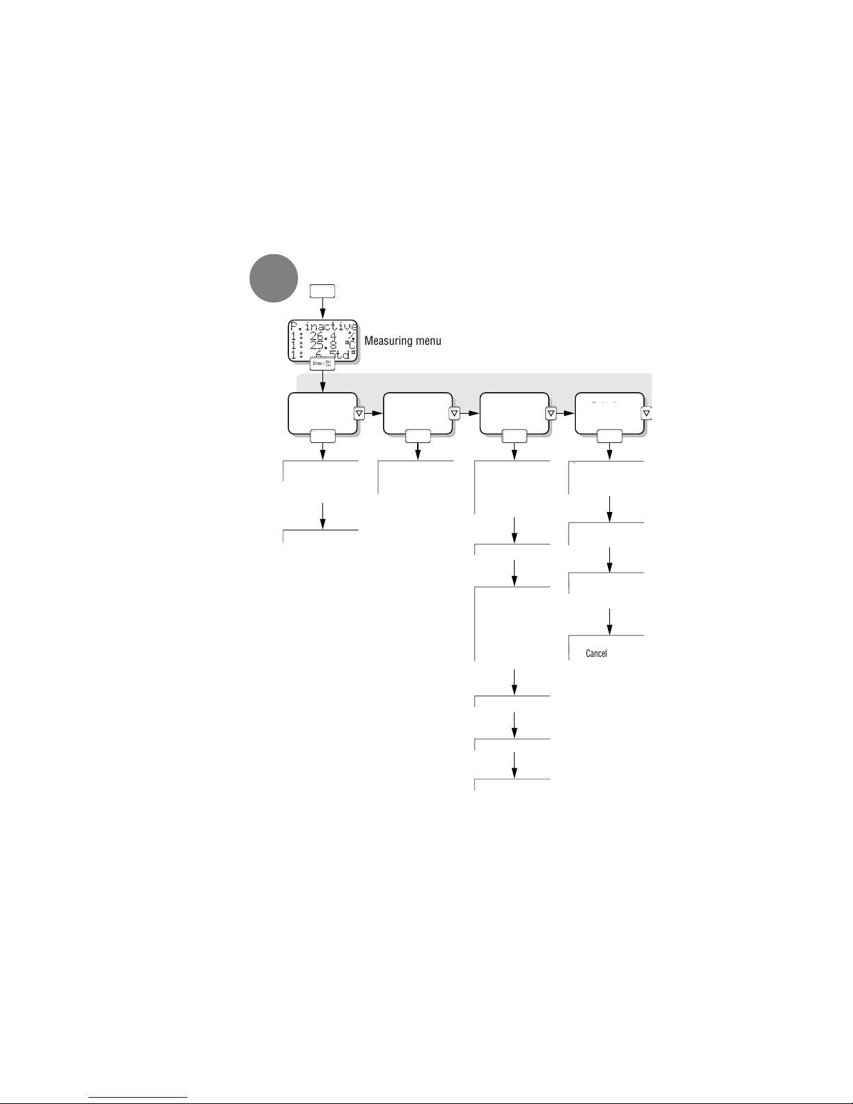
Multi-pt Mv
config.
Memory Printing
Collecting values and
multi-pt
Select parameter
Set time window
0-> point mv
View
Scroll through
protocol headings
Call up meas. val.
in the memory
Current mv
Display is printed
Mode
Protocol
Protocol selection
Set program
I, II, III
Starting criterion
Rate
Duration
Activate
programs
Settings
Measuring
programs
Minimum rate
Keylock
Reset
Ein
On
Enter /
Ein
On
Enter /
Ein
On
Enter /
Ein
On
Enter /
Ein
On
Enter /
P.inactive
1: 26.4 %
1: 25.8 °C
1: 6.5td°
Ein
On
Enter /
Measuring menu
Ein
On
Enter /
•
Quit
Main menu
Cancel
Cancel printout
testo
8
8.1 8.3 8.48.2
State
Print
Values
Page 9
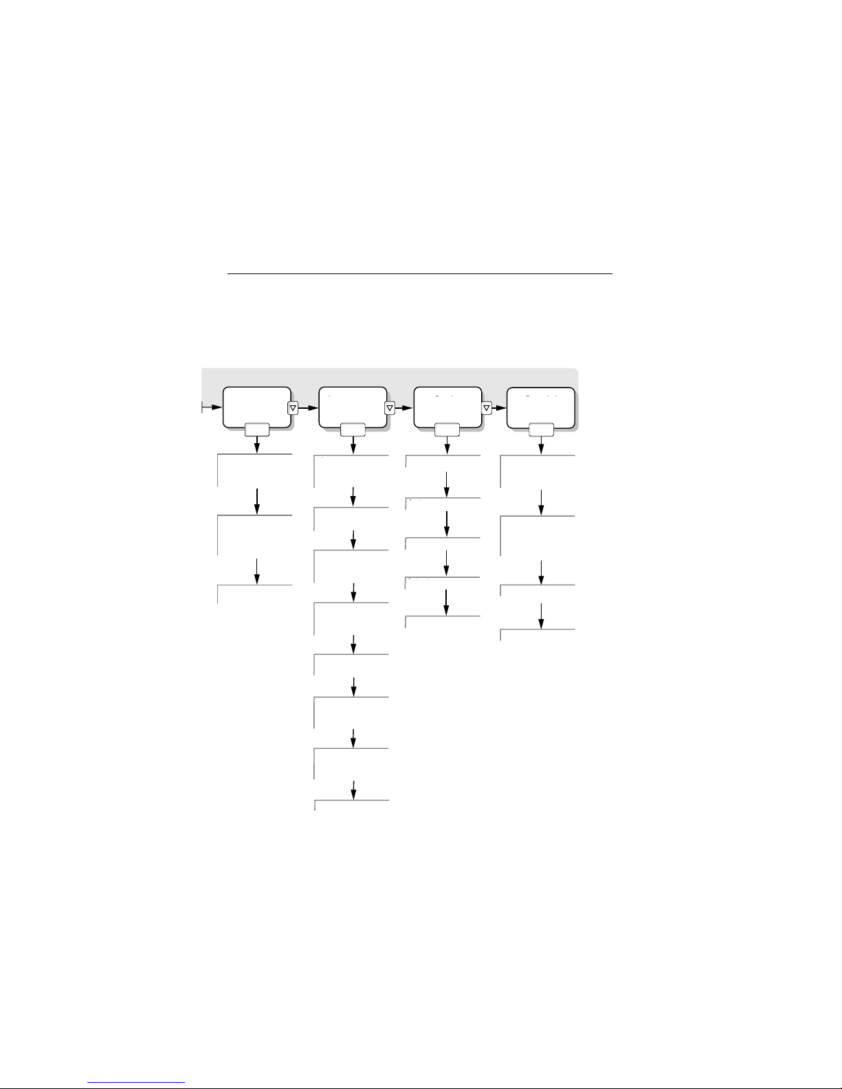
Location
Selection
List of locations
Select location
Enter
Enter
number or
capital letters
Erase
Location
Ein
On
Enter /
Ein
On
Enter /
Ein
On
Enter /
Ein
On
Enter /
Display
Configure:
select parameters
Unit
Speical function display
Automatic display
of derived values
Volume flow
Rd. cross-section
Sq. cross-
section
Density, manual
Absolute, manual
Date/Time
Displays/Correction
Rechargeable battery
Shows voltage
and capacity
Auto-Off
Activate
Deactivate
Intermediate rate
Enter rate
Alarm I
Configure
Activate
Instrument
Probe
Special
function
Alarm Il
Configure
Activate
Scale
Calibration
Selection
Erase
5Menu overview
9
8.5 8.6 8.7 8.8
Select
Device Probes
Scaling
Calibrate
Adjust
Discard
Specials
Flow volume
Pressure
Page 10
testo
454
Logger
testo
0
1
2
3
4
5
6
9
•
10...14V DC
Ein
On
Enter /
˛˛˛˛˛˛˛˛˛˛
˛˛˛˛˛˛˛˛˛˛
˛˛˛˛˛˛˛˛˛˛
˛˛˛˛˛˛˛˛˛3
P.inactive
1: 47.8 %
1: 23.4 °C
2: 47.8 %
testo
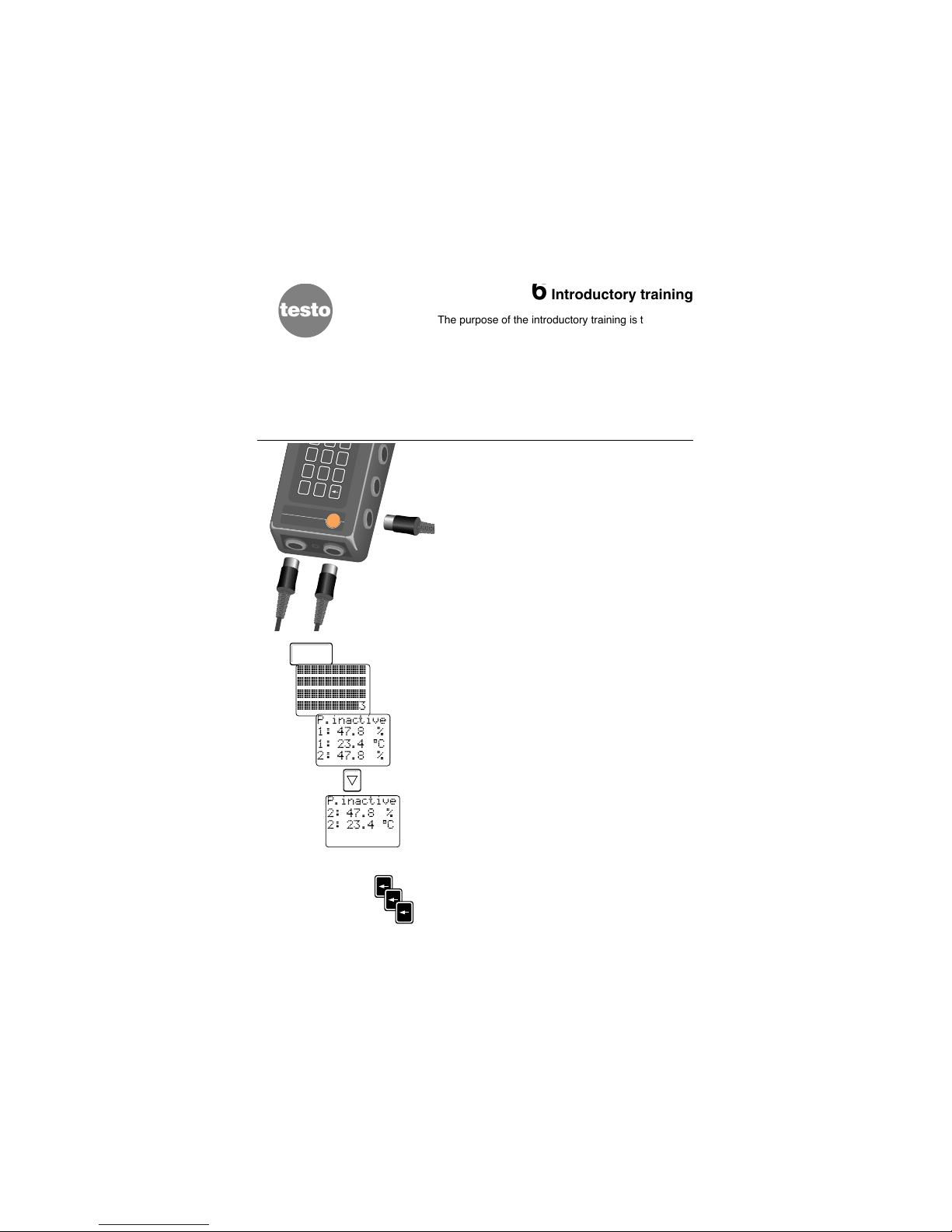
6Introductory training
The purpose of the introductory training is to make
the operation of the instrument easier for you.
Measuring, printing and saving is explained in short,
easy steps.
The functions of the testo 454 are described in
detail in Chapter 8.
Before using the instrument please check if the delivery is complete and undamaged.
6.1 Measuring
Connect one or more probes to the measuring instrument.
Irrespective of which sockets are assigned the measuring instrument recognises which sockets are
assigned and which probes are connected.
It is important that the probes are connected
before the instrument is switched on so that the
instrument can query the probe codes when switched
on.
Now switch on the measuring instrument.
A short function test is conducted. After several seconds the instrument is in the measuring menu and
the first set of information appears in the display.
The code of the respective measuring program is displayed in the top line. “P inactive” means that a
measuring program was not activated (refer to Chapter 8.3.3)
The measured values are shown in the lines below:
• the socket assignment is shown in the left
column
• the measured value is in the middle column
• the unit is in the right column
If you happen to go to the wrong menu when going
through the steps or if you simply do not know how to
proceed press the <Arrow> key several times and
you will return to the next highest menu and back to
the measuring menu.
10
P.inactive
2: 47.8 %
2: 23.4 °C
Page 11
6Introductory training
From the measuring menu go to the submenu “Print”
by pressing the key <6>, selection is on “MEASURED
VALUES”.
Switch on the printer.
Position the printer and the measuring instrument
such that the red control lamp is pointing in the direction of the infrared diode in the testo 454 measuring instrument.
Confirm the menu point selected “PRINT - M
EASURED
VALUES
” with <Enter>.
The printer immediately prints the current measured
values.
Ensure that the infrared connection from the
measuring instrument to the printer is not interrupted during the printing otherwise you may have
an incomplete printout.
Go back to the measuring menu after printing by
pressing <Arrow> twice.
6.3 Saving measured values
Save the current measured values out of the measuring menu via the <point> key.
“Act.Values stored Location: LENZKIRCH” appears
in the display. The location “LENZKIRCH” is set in
the factory. It is possible to change the measuring
location or to set up a selection of different locations
(see next page).
Return to the measuring menu by pressing <Enter>.
11
Print
Values
Protocol
Settings
6
P.inactive
1: 47.8 %
1: 23.4 °C
2: 47.8 %
•
Act.Values
stored
Location:
LENZKIRCH
Messwerte
01.01.94 03:27:18
3: 34.5 %
3: 23.3 °C
3: 6.8td°
4: 48.2 %
4: 23.3 °C
4: 11.8td°
Ein
On
Enter /
Ein
On
Enter /
P.inactive
1: 47.8 %
1: 23.4 °C
2: 47.8 %
0
1
2 3
4
5 6
7
8 9
•
Aus
Off
Ein
On
Enter /
Drucken
µesswerte
Protokoll
Einstell.
6.2 Printing the measured values on the infrared printer
Page 12
Main menu
Memory
Print
¬ocation
>HA
å
B
C
Ein
On
Enter /
>H
F
G
ª
testo
6Introductory training
12
Main menu
µulti-pt
Mv config
Memory
Ein
On
Enter /
Ein
On
Enter /
Location
‚elect
Enter
Erase
Location
Select
™nter
Erase
>
˛
A
B
Ein
On
Enter /
Ein
On
Enter /
1
Ein
On
Enter /
3
Ein
On
Enter /
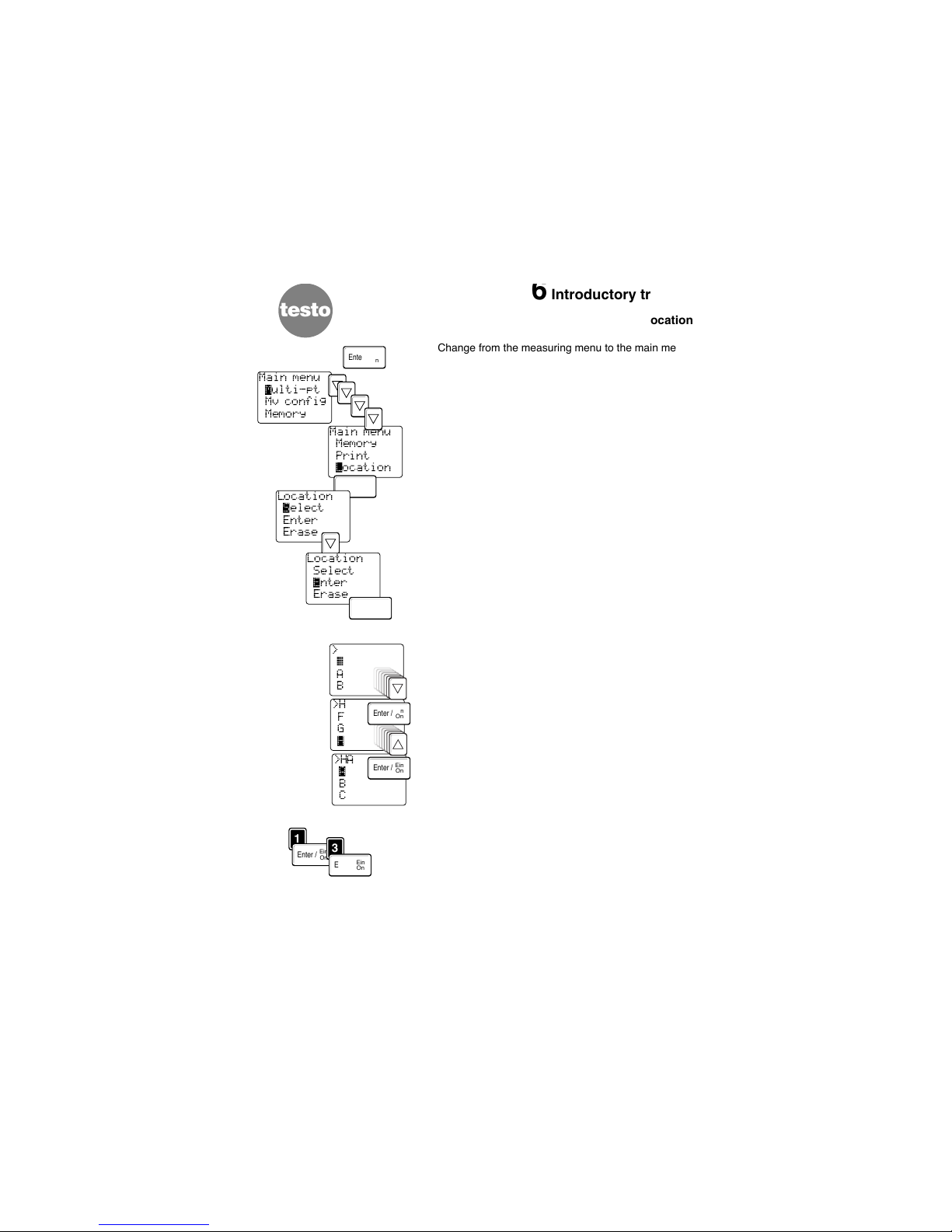
6.4 Setting up a location
Change from the measuring menu to the main menu
by pressing <Enter>.
Move the cursor to “LOCATION” by pressing <down>
4 times and confirm by pressing <Enter>.
Select the submenu “ENTER” via the <down> key
and activate it by pressing the <Enter> key.
Now enter a location in this submenu with up to 9
characters.
Select letters via <up><down>; the letters confirmed
with <Enter> are written in the top line.
Numbers can be entered directly via the <0…9>
keys.
In order to save the location in the selection the top
line has to be filled right up to the 9th digit (e.g. with
blanks “_” ).
Page 13
6Introductory training
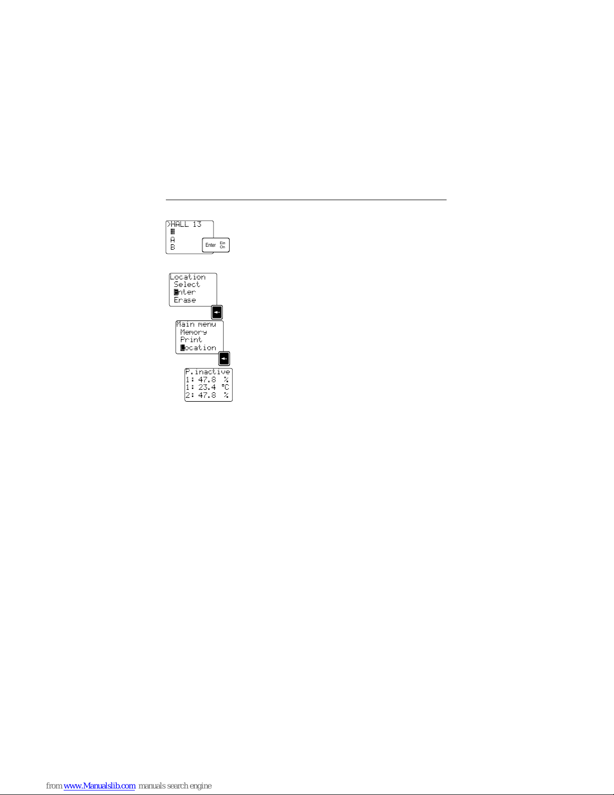
6.4 Setting up a location
Confirm the input location with <Enter>.
You are again in the “Location” menu.
By pressing the <Arrow> key twice you go back to
the measuring menu via the main menu.
13
>HALL 13
˛
A
B
Ein
On
Enter /
Location
Select
™nter
Erase
Main menu
Memory
Print
¬ocation
P.inactive
1: 47.8 %
1: 23.4 °C
2: 47.8 %
Page 14
7Operating instructions
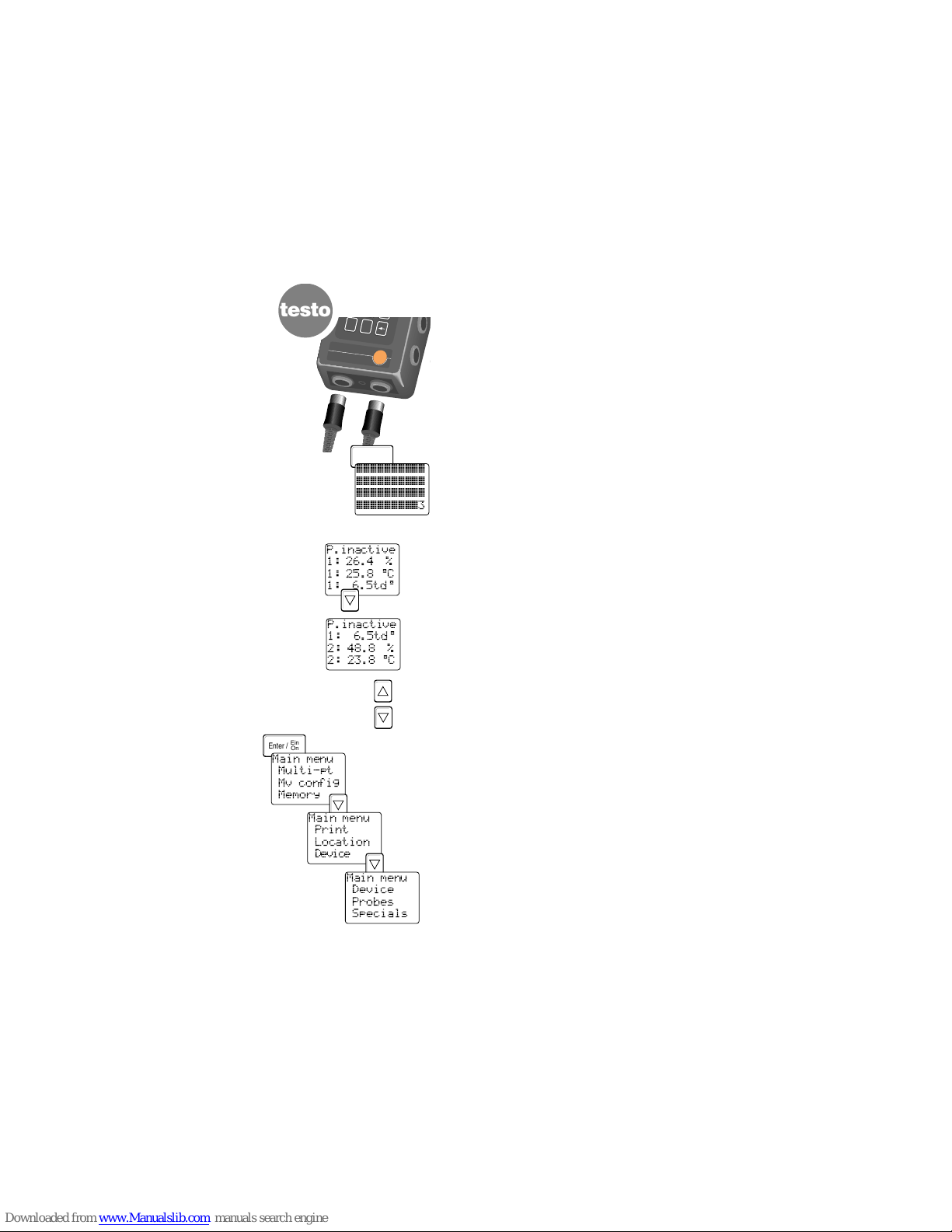
7.1 Measuring
When measuring the probes must be connected
before the instrument is switched on.
Insert one or more probe plugs into the data logger
socket(s). It does not matter which socket you
choose as the data logger recognises the assignment of the input channels and the probes connected.
Switch on the instrument.
A short function test is carried out.
The instrument then goes to the measuring menu.
A 4 line display appears.
The first line shows the program status, in this case
“P. inactive” for program inactive which means that a
measurement is not activated (activated programs
wait on the respective programmed starting criterion,
see Chapter 8.3.3).
The current measured values are shown in the following lines. The input channel (socket no.) is shown
in the left column while the current measured value is
shown in the right column.
Using <up>/<down> the measured values can be
scrolled up and down in the display (if more than 3
are active).
Leave the measuring menu by pressing <Enter> and
change to the main menu.
The main menu includes the following submenus:
Averaging Chapter 8.1
Mean value configuration Chapter 8.2
Memory Chapter 8.3
Print Chapter 8.4
Location Chapter 8.5
Device Chapter 8.6
Probes Chapter 8.7
Specials Chapter 8.8
14
testo
454
Logger
testo
0
•
10...14V DC
Ein
On
Enter /
˛˛˛˛˛˛˛˛˛˛
˛˛˛˛˛˛˛˛˛˛
˛˛˛˛˛˛˛˛˛˛
˛˛˛˛˛˛˛˛˛3
P.inactive
1: 26.4 %
1: 25.8 °C
1: 6.5td°
P.inactive
1: 6.5td°
2: 48.8 %
2: 23.8 °C
Ein
On
Enter /
testo
Main menu
Multi-pt
Mv config
Memory
Main menu
Print
Location
Device
Main menu
Device
Probes
Specials
Page 15

8Main menu
8.1 Averaging
The parameters, taken as a basis when averaging,
are defined by you in the menu point “MV
CONFIG
”.
A measuring rate of 1 second is the basis for averaging. The time is defined in the menu “MV
CONFIG”.
Select “M
ULTI-PT” from the main menu.
Measurement is started via the <Point> key.
The mask gives information on the
- remaining averaging time in seconds,
- number of averagings,
- parameter to be averaged (unit),
- current measured value,
- averaged measured value.
An averaging calculation which has been started can
be cancelled with the <Arrow> key and the measured
values are not saved. When leaving the menu by
pressing <Enter> the individual mean values and the
total mean values are automatically saved as a
protocol with the current location. Saved mean values can be called up in the menu “V
IEW MEMORY”.
8.2 Mean value configuration
Open the “MV CONFIG” menu.
Select a channel (=Parameter) via <up>/<down>.
Confirm with <Enter>, the cursor jumps to the next
line.
Enter the duration of the averaging in seconds (three
digit value e.g.
030
). Confirm with <Enter> and you
return to the main menu.
If you wish to check the entry or take an average
directly move the cursor via <up> to “M
ULTI-PT” and
confirm with <Enter>.
Proceed in the “M
ULTI-PT” menu as described above.
15
Main menu
Multi-pt
Mv config
Memory
Channel
∆1: %
Duration
10 s
Channel
∆2: °C
Duration
10 s
Ein
On
Enter /
Ein
On
Enter /
Channel
K1: %
Duration
˛10 s
Main menu
Multi-pt
µv config
Memory
Channel
K1: %
Duration
125 s
1
2
5
Ein
On
Enter /
Time 5 s
No 2 %
Act 27.7
Mv 26.9˛
Time s
No 0 %
Act 27.7˛
Mv
Ein
On
Enter /
•
.....
Page 16

testo
8.3 Memory
8.3.1 View
All of the completed measuring programs and averages are saved in numerical order.
Via the menu point “M
EMORY: VIEW”
an information mask appears which shows you the
number of protocols (“
PROTOCOLS
”) already available.
In the following masks you will see the protocol headings of the saved protocols:
1st line: - Protocol number and measuring location
2nd line: - Number of measuring channels (Kor
MW
in average protocols
- Number of measured values (W)
3rd line: - Date
4th line: - Time (start of protocol)
Select a heading via the <up><down> keys and call it
up via <Enter>.
The 1st line of the protocol contains information on
the channel and the parameter of the listed measured values. The other channels are reached via
<Enter>.
You can scroll through the measuring protocol to the
last measuring value via <up><down> keys.
You can return to the “M
EMORY: VIEW” menu by
pressing the <arrow> key.
8.3.2 State
Select the “S
TATE ” menu point from the “MEMORY”.
The following display includes:
2nd line: - used kByte
3rd line: - free kByte
4th line: - free memory in %
Your testo 454 has a memory capacity of
224 kByte which corresponds to 110,000 measured
values. Return to the “MEMORY” menu by pressing the
<arrow> key and go to the measuring menu via
<Enter>.
8Main menu
16
Protocol
13
Main menu
Multi-pt
Mv config
µemory
Memory
√iew
State
Prog. I
Memory
√iew
State
Prog. I
1 Testo
12K, 120W
16.03.94
12:01:46
1°C
1 19.2
2 19.2
3 19.2
1°C
2 19.2
3 19.2
4 19.4
2%
1 31.6
2 31.9
3 32.1
2 Testo
MW % 3W
16.03.94
13:25:57
Ein
On
Enter /
Ein
On
Enter /
Ein
On
Enter /
Memory
View
‚tate
Prog.I
Memory
Used: 9kB
Rem:215kB
Free:93%
Ein
On
Enter /
Ein
On
Enter /
Ein
On
Enter /
Page 17

8Main menu
8.3 Memory
8.3.3 Programs 1-3
Measurements can be controlled via 3 freely definable measuring/saving programs. The
channel, starting criteria, measuring rate, measurement duration or number of values are
defined in the programs 1-3. The programs are started once the “starting criterion” is fulfilled. The starting criterion is checked at the measuring rate: if a slow rate has been set it
is advisable to set a an intermediate rate when checking the starting criterion (see Chapter
8.6.5). All 3 programs can be started independently of each other, they save all of the connected probe values at the set measuring rate. “Programming 1” can be taken as an example for all 3 programmings.
17
Example 1: Measurement with activated “Program 1”, Starting criterion: “Overrun”
Example 2: Measurement with two activated programs (Prog. 1 and Prog. 2),
Starting criteria: “Exceeding”
Display, channel 1
Display, channel 1
Time
Time
Limit value of
starting criterion
”Exceeding”
Limit of starting
criterion
“Exceeding”
Prog. 2
Limit of
starting criterion
“Exceeding”
Prog. 1
Prog.1
active
Prog. 2
active
Start of program 1 when
the programmed starting
criterion is entered
xxxxx =
Checking the
starting criterion
at a quicker rate
(“Device” menu,
“Intermediate
rate” submenu)
End of program 1, the starting
criterion is lifted
The program can be ended prematurely via “Measuring rate” or
“Number of values
Progression of parameter at channel 1
Progression of parameter at channel 1
x x x x x x x x x x x x x x x x x x x x x x x x x x x x x x x x x x x x x x x x
Prog.1
active
Changing measuring rate e.g. high
resolution in critical areas
Data acquisition corresponding to the
“Measuring rate”
Page 18

testo
8 Main menu
Ein
On
Enter /
Ein
On
Enter /
Ein
On
Enter /
Ein
On
Enter /
Ein
On
Enter /
Ein
On
Enter /
Memory
View
State
πrog.I
Prog.Start
Ext.Signa
Prog.Start
Time
02.06.93
12:23:47
Prog.Start
Overrun
K1: %
+ 50.00
Prog.Start
Underrun
K1: %
+ 50.00
Prog.Start
Gradient
K1: %
5.00
8.3 Memory
8.3.3.1 Program starting criterion
Select a starting criterion:
External signal
The starting command is triggered when an external
voltage signal is input. Please use the lead
0554.0012 (See Ordering data) when inputting an
external voltage signal. In the case of a trigger circuit
the limit values of the trigger input must be adhered
to (Refer to Technical data). The trigger input in
testo 454 is electrically isolated from the other
circuit.
Time
The program start is made dependent on the date
and time. If the instrument is switched off the start is
delayed by approximately 5 seconds until the instrument has completed the function test and probe recognition.
Overrun
Saving begins when the measured value of a parameter, defined by you, overruns on a channel specified
by you. An intermediate rate is recommended to
check the starting criterion frequently (see Chap.
8.6.5).
Underrun
Saving begins when the measured value of a parameter, defined by you, underruns on a channel specified by you. An intermediate rate is recommended to
check the starting criterion frequently (see Chap.
8.6.5).
Gradient
The program is started once the measured value of a
specified parameter in the defined channel changes
quicker than that of the limit value defined by you.
The specified value refers to:
∆ t = 1 s
The display opposite means that
the program is started when the measured value
changes by more than 5 %RH in 1 second.
Difference
When the differential value (of a parameter) in two of
the channels specified by you is overrun measurement is started. If, for example, the temperature of
K1 is 50 °C below that of K2 the program is started.
∆ <w>
∆ t
Programm
Rate
˛1s
Prog.Start
Difference
K2: °C -K1
25.00
Ein
On
Enter /
18
Page 19

8 Main menu
8.3 Memory
Note on the differential trigger programming in
combined probes:
If combined probes are used for the starting criterion
“Difference” there is not enough space in line 3 of the
display to show clearly the channel and the parameter.
In the 3rd line of the display opposite only “K2”
appears at the end of the line. The parameter is allocated correctly by numbering the key confirmations
of <up> <down>.
The confirmation of a starting criterion via <Enter>
triggers a jump to the"PROGRAM RATE" parameter.
Prog.Start
Difference
K2: °C -K2
10.00
19
Note:
The program end criterion is delayed in relation
to the programmed start limit value (hysteresis):
the program continues saving for a short time
even though the programmed limit value is no
longer overrun.
Page 20

testo
8.3 Memory
8.3.3.2 Rate
Specify the rate at which the measuring instrument
should save the probe data during this measurement.
Entries from 0.1 seconds to 24 hours are possible.
Seconds can be given in fractions. Minutes and hourly rates are usually whole numbers. All values are
saved according to the probes connected.
8Main menu
20
Program
Rate
˛1s
Ein
On
Enter /
Please note that some measuring time must be
allowed for each connected probe since the sockets
must be serially checked.
The probe with the longest measuring time
defines the minimum measuring rate.
The following is the time required for each probe:
Hum. probe °C/%RH w. dew-point .0.3 seconds
Vanes . . . . . . . . . . . . . . . . . . . . . . . .0.7 seconds
Shell anemometer . . . . . . . . . . . . . .2.2 seconds
Frequency sources . . . . . . . . . . . . .0.7 seconds
Pt100 probes . . . . . . . . . . . . . . . . .0.1 seconds
Other . . . . . . . . . . . . . . . . . . . . . . . .0.2 seconds
In the menu MIN.RATE (See Chap. 8.3.4) the shortest measuring rate depending on the probes connected can be checked.
0
Page 21

8.3 Memory
8.3.3.3 Activating duration and program
By confirming the input "PROGRAM RATE
"with <Enter>
you will go to the input mask "P
ROGRAM DURATION
".
You have 3 ways of defining the program duration:
1) as a time range (=“Duration”)
2) as a “# of values”
3) as an “Open End” measurement i.e. the measure-
ment runs until the memory is full or crashes.
If the trigger function refers to measured values, the
number of saved values can be lower than the number
of values programmed to be measured. Cause: the program running was prematurely interrupted because of
the following:
- a second activated program has been
started or
- the starting criterion for the current
program has not been fulfilled.
Confirm your entries with <Enter>.
To activate the program, switch the display
“activ.off” to “activ.on” via <up> <down>.
The program can be activated at any time.
When confirmed with <Enter> the measuring instrument takes over programming and goes back to the
"MEMORY" submenu.
8Main menu
21
Program
∂uration
0 sec
activ.off
Program
# of val.
activ.off
Program
øpen End
activ.off
Program
Open End
Å
activ.off
Program
Open End
active.øn
Memory
View
State
πrog.I
A.P:1e
1: 24.4 %
1: 22.5 °C
1: 1.3td°
Ein
On
Enter /
Ein
On
Enter /
•
Page 22

testo
8.3 Memory
The active programmings are indicated in the measuring menu. The first line in the example opposite
displays the following code:
A
= active,
P:1
= Program 1, e= start crit. extern. signal
A
= Active
P:1 - P:3
= Active program 1 - 3
e
= External trigger / external signal
t
= Time trigger / time plan
w
= Value trigger / Overrun/Underrun etc.
w
= Difference
w
= Gradient
P.2:321:
= Program 2 is running, 321 values are
currently saved (in this protocol)
You can start the following from the measuring menu:
- program 1 with <1> key
- program 2 with <2> key
- program 3 with <3> key.
8.3.4 Minimum rate
The “M
IN. RATE ” menu shows the specified minimum
rate of the probes connected. This value cannot be
underrun when programming the instrument.
Select “M
IN.RATE ” from the memory menu list and
confirm with <Enter>.
8Main menu
Memory
øn.rate
Keylock
Reset
Min.rate
0.4 s
Ein
On
Enter /
Ein
On
Enter /
8.3.3.4 Overview of the programming system
22
A.P:1e
1: 24.4 %
1: 22.5 °C
1: 1.3td°
Function required Here´s how....
Start program with instrument - Select program
switched on - Switch off Auto Off function (See
Chapter 8.6.4)
- Check charge in rechargeable batteries or
connect mains unit
Start program with instrument
switched off
Starting criterion: Time plan or trigger - Carry out settings
- Switch off instrument
Starting criterion: Overrun/underrun - Set limit values and parameter
or gradient or difference - Set and activate intermediate rate
- Switch off instrument
Note: Activated measuring programs (P1 – P3), which take measured values as the basis
for starting criterion, are executed with the instrument switched off only if the intermediate
rate and the measuring rate are set at more than 1 minute. For rates of less than 60 seconds the instrument must be switched on to start the measuring program. The Auto-Off
function then has to be deactivated.
Page 23

8.4 Printing
Via the print menu you can control whether you wish
to print the following:
- current measured values
- a particular protocol
- activated settings with reference to
Programming I, Programming II,
Programming III, Alarm 1 or Alarm 2
Before operating the printer please read the
enclosed Instruction Manual.
If “CANCEL” is selected the instrument completes the
current (processed internally) block and printing is
stopped after max. 10 lines.
8Main menu
23
Print
Values
Protocol
Settings
Values
01.01.94 03:27:18
3: 34.5 % 3:
23.3 °C 3:
6.8td°
4: 48.2 % 4: 23.3
°C 4: 11.Std°
Print
Values
∏rotocol
Settings
Protocol
11 Shaft 7
3K, 15 W
13.12.93 10:00:00
13.12.93 10:00:00
%RH °C td°
1 33.6 20.4 3.9
2 33.6 20.4 3.9
Print
‚ettings
Cancel
Settings
Prog.Start 1
Ext.Signal
Rate:0.50 s
# values:100
Prog.Start 2
Ext.Signal
Rate:1.00 sec
# values:150
Memory
Min.rate
Keylock
®eset
Memory
Min.rate
∆eylock
Reset
Keylock
off
Keylock
on
Memory
Min.rate
Keylock
®eset
Ein
On
Enter /
Ein
On
Enter /
Ein
On
Enter /
Reset
Erases
everyth.
OK
Ein
On
Enter /
8.3 Memory
8.3.5 Keylock
In this submenu the hot key function for the keys
<1>,<2> and <3> can be switched on or off which
means that when the keylock function is switched on
it is not possible to activate a program from the
measuring menu via the keys <1>,<2> and <3>.
8.3.6 Reset
Beware. Overrun
Using this command you can erase the complete
data memory. It is not possible to delete selected
protocols. Configuration, measuring programs etc.
remain.
Select the submenu “R
ESET” from the menu “MEMO-
RY
” and press <Enter>. The whole memory is
erased.
You then return to the “M
EMORY
” menu.
During the inquiry “
RESET, ERASES EVERYTH., OK” it is
possible to cancel the process with the <Point> key.
Page 24

Device ...
∂isplay
Date,Time
Rech.bat
Display
˛1:K1: %
2:K1: °C
3:K2: %
˛1 :K1: %
Min off
Max off
AVG
1 :K1: %
Min øff
Max off
AVG
1 :K1: %
Min øn
Max off
AVG
1 :K1: %
Min on
Max øff
AVG
Display
1:K1: %
˛2:K1: °C
3:K2: %
testo
8Main menu
8.5 Measuring location
8.5.1 Selection
Via the <up>/<down> key select the location relevant
to the measurement from the locations saved here
and confirm via <Enter>.
The selected designation is saved with the measured
values. The latter appears on printouts from the infrared printer and in the protocol head (Refer to the
Chapter 8.3.1 “Memory: View”).
8.5.2 Enter
Select “L
OCATION-ENTER”.
Select a letter via the <up><down> keys and confirm
via <Enter>. The numbers can also be entered (e.g.
“
HALL 3
”). The line must be filled right to the end
(e.g. B. with blank). This is the only way to complete
the entry before returning to the “L
OCATION
” menu.
The location entered is now available via
“S
ELECT
”.
8.5.3 Erase
In order to maintain an overview it is possible to
erase entries. Select the location which you want to
erase via the <up>/<down> key and press <Enter> to
confirm.
8.6 Device
8.6.1 Display
The display contains the current measured values of
the connected probes. In addition to the measured
values the minimum, maximum and mean values can
be displayed.
Once you have selected the submenu “D
ISPLAY” from
the “D
EVICE” menu you can look for the respective
channel and the required parameter via the
<up><down> keys. Confirm the selection via
<Enter>.
With <Enter> you also select “M
IN”, “MAX” and/or
“AVG”, switch the display “on” or “off” with
<up><down>.
This setting depends on the constellation and is lost
when the instrument is switched off.
Go from the “Display” menu back to the “Device”
menu by pressing <Arrow>.
24
Location
‚elect
Enter
Erase
Location
Select
™nter
Erase
Location
Selection
Enter
™rase
>
_
A
B
Locations
Testo I
Testo II
Locations
Testo I
Testo II
Ein
On
Enter /
Ein
On
Enter /
Ein
On
Enter /
Ein
On
Enter /
Ein
On
Enter /
Ein
On
Enter /
Ein
On
Enter /
Ein
On
Enter /
Ein
On
Enter /
Ein
On
Enter /
...
...
Ein
On
Enter /
Page 25

8.6.3.1 Notes on battery operation
- In order to protect the instrument from total discharge when not operating connect it for one
day a month to the mains unit.
- If “Emergency” is displayed, a one-minute refresh cylce takes place which regenerates the
run down rechargeable battery. The red LED lights up in the battery charger. If the cycle has been
successfully completed “Charge quickly” appears in the display. If the refresher impulse was
insufficient the procedure can be repeated by switching the mains unit on and off with the instrument switched off. If the instrument does not go into the fast recharging mode the rechargeable
battery is defect. In order that the complete battery capacity is available the recharging cycle
should be repeated 2 - 3 times following total discharge.
- A recharging cycle takes approx. three hours and is displayed by the instrument by going from
“Quick” to “Conserve”. The compensation charge fills the rechargeable battery completely.
- The charge is active if testo 454 if switched off and the mains unit is connected or if the mains
unit is connected when the instrument is switched off.
- If the mains unit is plugged out during rapid recharging the instrument deactivates itself within one
second. Deactivation can take two minutes in the conservation mode.
- Long-term measurements should be started with a newly charged battery.
- The capacity of the rechargeable battery is correctly displayed in the instrument menu 4 hours
after charging.
- The operating limits of the rechargeable battery are shown with ”LowBat” or ”TempOut”.
8.6.3.2 Examples of the service life of testo 454
The service life depends on the probe assignment and the measuring rate. The following is a list of
typical examples which influence the service life of the rechargeable battery.
8Main menu
8.6 Device
8.6.2 Date/Time
Enter the date in the format DD:MM:YY, the time in
the format hh:mm:ss.
Confirm the entry of the numbers with <Enter>.
8.6.3 Rechargeable battery
The battery charge is shown by the voltage available,
instrument temperature and the capacity of the
rechargeable batteries (
ччччч
= Battery charged).
25
Device...
Display
∂ate, Time
Rech.bat
Ein
On
Enter /
Device....
Display
Date,Time
®ech.bat
Accu
Volt:8.5V
Tem: 26°
Cap:ччччч
Ein
On
Enter /
Date/Time
“¡.03.94
11:18:06
2
2
Ein
On
Enter /
Date/Time
22.≠¶.94
11:18:06
2
2
Ein
On
Enter /
Connection Warm up time Meas. rate Service life
approx.
1 x thermal anemometer (70 mA) 20 s 30 min 5.0 days
6 x thermocouple None 30 min 15 days
1 x thermal anemometer (70 mA) 20 s 10 min 2.7 days
1 x digital humidity (10 mA) 2 s 10 min 9.0 days
Page 26

testo
8Main menu
8.6 Device
8.6.4 Auto-Off
The instrument automatically switches off after 10
minutes when not used if the Auto-off function is on.
This helps to save the batteries and hence the
environment. Key confirmations, serial communication, measuring programs with a measuring rate of
less than one minute which have been already started keep the instrument “awake” and it is not switched
off automatically.
Note: Activated measuring programs (P1 – P3) which
take the measured values as a basis for the starting
criteria are only executed if the intermediate rate and
the measuring rate are set at longer than 1 minute.
For rates less than 60 seconds the instrument should
stay switched on in order to start the measuring program. The Auto-Off should then be deactivated.
Make sure to switch off the instrument when you
are not using it and the auto-off function is off.
8.6.5 Intermediate rate
Indicate the time intervals within which the measuring
instrument has to check the conditions for a measurement (program start at overrun or underrun of
measured value or gradient). If you do not activate
this input the instrument only checks the conditions if
switched on or if the running program is at the set
measuring rate. This input is valid for all programs
and alarms.
Note: Intermediate rates in the seconds range are
not possible if the measuring rate is > 50 min i.e. the
minimum intermediate rate is 1 min.
26
Ein
On
Enter /
Device...
Date,Time
Rech.bat
åuto-Off
Power off
10 min
later
øff
Power off
10 min
later
øn
Ein
On
Enter /
Device...
Rech.bat
Auto-Off
⁄m. rate
Device
Rech.bat
Auto-Off
⁄m. rate
Interm.
rate
˛ 1 sec
activ.off
Interm.
rate
002 ˛
activ.off
Interm.
rate
002 ˛in
activ.off
Interm.
rate
002 min
activ.˛ff
Interm.
rate
002 min
activ.on
0
6
6
Ein
On
Enter /
Ein
On
Enter /
Ein
On
Enter /
Page 27

8Main menu
8.6 Device
Select an alarm criterion:
Overrun
The alarm is triggered when the parameter measured
value, defined by you, overruns on a specified channel. An intermediate rate is recommended to check
the alarm criterion frequently (see Chapter 8.6.5).
Underrun
The alarm is triggered when the parameter measured
value, defined by you, underruns on a specified
channel. An intermediate rate is recommended to
check the alarm criterion frequently (see Chapter
8.6.5)
Gradient
The alarm is triggered once the measured value of a
specified parameter in the defined channel changes
quicker than that of the limit value defined by you.
The specified value refers to::
∆ t = 1 s
Difference
When a differential value (of a parameter) in two of
the channels specified by you has been overrun the
alarm is triggered.
Confirm your selected alarm criterion with <Enter>.
27
Ein
On
Enter /
Ein
On
Enter /
Ein
On
Enter /
Ein
On
Enter /
Ein
On
Enter /
Device
Auto-Off
Im.rate
ålarm I
Alarm off
øverrun
K1: °C
+123.4
Alarm off
©radient
K1: °C
15.00
Alarm off
∂ifference
K1: °C-K1
38.00
Alarm off
¨nderrun
K1: °C
+123.4
∆ <w>
∆ t
8.6.6 Alarm
testo 454 offers two alarm outputs whose trigger criteria, separated from each other, can
be defined in the menu “D
EVICE”, submenu “ALARM”. The alarm is controlled when the
measuring program is running or not running. The alarm outputs are electrically isolated
from the usual wiring parts in the testo 454 but are connected to one another.
Please use the cable 0554.0012 available as an accessory. The alarm output is switched
through and remains active as long as one of the following alarm criteria applies. The gradient is the exception which remains active if once activated and can only be switched off
manually (“Alarm off”).
Page 28

Alarm off
Overrun
˛2:m/s
+35.00
Alarm off
Overrun
K2:m/s
+˛5.0
Alarm off
Overrun
K2: m/s
˛32.0
Alarm øff
Overrun
K2: m/s
+32.00
Alarm øn
Overrun
K2: m/s
+32.00
testo
8Main menu
8.6 Device
After having confirmed your alarm criterion select the
channel required and the respective measuring units
using the <up>< down> keys. Confirm your input by
pressing <Enter>.
Enter the limit required in the bottom line and confirm
by pressing <Enter>.
Set the top line to “Alarm on” via <up><down> and
confirm with <Enter>. You then return to the
“DEVICE” menu.
The example opposite is representative for all alarm
criteria.
The alarm remains active for as long as the measured value fulfills the alarm criteria selected.
The settings in the “Alarm 1” and “Alarm 2” settings
remain even after the instrument has been switched
off.
8.6.7 Units
Converting the units:
°C
{ °F
hPa { inW (inch Water column)
m/s { fpm
With <Enter> you can choose the parameters in the
menu “U
NITS”. Change the unit with <up><down>
(see above).
Quit this menu by pressing <Enter>.
These settings apply to all channels and remain set
after switching off the instrument.
28
Device
Alarm I
Alarm II
¨¨nits
Ein
On
Enter /
Units
˛C
hPa
m/s
Ein
On
Enter /
Units
°C
ÓPa
m/s
Units
°C
ÛnW
m/s
Alarm off
Overrun
˛1: °C
+123.4
Ein
On
Enter /
Ein
On
Enter /
Ein
On
Enter /
Device
Auto-Off
Int. rate
ålarm I
(Select “+” or “–”)
Ein
On
Enter /
Page 29

8Main menu
8.7.1 Unit
The probe prepared with the current/voltage cable is
connected to the measuring instrument. The measuring range has to be set in the current/voltage cable
before the instrument is switched on. Please observe
the permissible measuring ranges.
Select the unit of your probe in the “P
ROBES” menu.
Go back to the “PROBES”menu.
8.7.2 Scaling
In the menu “Scaling” you can change or enter the
upgrade and the offset of a probe manufactured by
another company or of a measuring transducer. The
entry of A1 and AO is based on the formula
f(x) = A1 *x + AO
A1 is the upgrade and A0 is the offset from the zero
point. The + or - signs can be changed via
<up><down> and confirmed with <Enter>. Then
enter the respective numerical value and confirm
your entry with <Enter>.
Return to the “P
ROBE” menu via <Arrow>.
8.7.3 Calibration
Calibration is possible in this menu point if CO
2
probes are available. Please note the probe description.
29
Probes
¨¨nit
Scaling
Calibrate
Probes
Unit
‚caling
Calibrate
Probes
Unit
Scaling
çalibrate
Unit
K1: %
Units
°C
°F
%
8.7 Probes
Probes other than Testo probes which have a voltage output of 0 to 1 V or a current output
of 0/4 to 20 mA can be connected to the testo 454. The current/voltage cable no.
0554.0007 is offered for this. This cable is equipped with an automatic recognition of the
respective input signal, so that you can assign a unit and a scaling to this signal (as
described below in the “UNIT
” menu).
There is also the possibility to measure voltages, frequencies and resistances with the
adapter cable no. 0554.0013. These parameters are not automatically recognised and
have to be preprogrammed in the menu “S
ELECT”.
Ein
On
Enter /
Ein
On
Enter /
Scaling
K1: %
K1: %
A1 +6.24
A0 -24.60
Ein
On
Enter /
Ein
On
Enter /
Ein
On
Enter /
Page 30

testo
8Main menu
8.7 Probes
8.7.4 Adjust
When using the adapter cable no. 0554.0013 the
instrument has to be told what parameter is to be
measured. You can choose between voltage, frequency and resistance. Select an input channel from
the non-assigned socket and confirm with <Enter>.
After this you can assign the required parameter to
the channel selected.
Now the corresponding unit can be determined in the
“UNIT” menu and the upgrade in the “SCALING” menu.
8.7.4 Discard
Probes which were defined under “ADJUST” must be
discared before a new configuration. Otherwise the
set unit is displayed on the channel selected. (even
if the probes are not connected). If a probe is connected which is different to that defined the display“Invalid configuration” appears after the instrument is
switched on and all of the settings are erased.
Confirm the channel input whose definition you wish
to erase in the “DISCARD” menu. The instrument
restarts and you then find yourself in the measuring
menu.
30
Selection
K2:______
K3:______
K4:______
Sensortype
1V
kHz
Ohm
Probes
Scaling
Calibrate
ådjust
Probes
Calibrate
Adjust
∂iscard
Discard
K2: mV
K3: kHz
Restart
to
activate
Ein
On
Enter /
Ein
On
Enter /
Ein
On
Enter /
Ein
On
Enter /
Ein
On
Enter /
Ein
On
Enter /
Page 31

Flow vol.
round
10.0 mm
Flow vol.
round
˛0.0 mm
Flow vol.
round
12.5 ˛m
8.8 Specials
8.8.1 Special functions display
Special functions, calculated from the measured values of the connected probes, are displayed in the
measuring menu if they are activated in the
“S
PECIALS.” menu.
td = Dew point (Combination probes %RH - °C)
m
3
/h = Volume flow (Velocity probe)
The accuracy of the volume flow display
follows from the accuracy of the velocity
measurement. Multiply the maximum and
minimum possible velocity value in the
accuracy data by the cross-section to get the
permissible deviation of the volume flow
measurement.
m/s = Air velocity (pressure probe)
The Pitot tube differential pressure is
converted to air velocity. Here the air density
is entered as a parameter (see Appendix
“Probe description”).
Switching on or off is carried out via <up><down>
and your entry is confirmed via <Enter>.
The special functions selected are activated by a
restart. The settings remain even after the measuring
instrument is switched off.
8.8.2 Flow volume
Enter the dimensions of the air channel (round,
square, cross-section area). The measuring instrument calculates the flow volume set in
“SF
DISPLAY”(see above).
8.8.3 Density
The density is required for the conversion of the
dynamic pressure into velocity. Please find the corresponding value in the enclosure Measuring engi-
neering.
8.8.4 Pressure
The air pressure is required for the compensation of
the CO
2
probe and the pressure probe (Pitot tube).
Refer to the more detailed description in the enclosure Measuring engineering.
Specials
‚F-no.
Flow vol.
Density
Specials
td øn
m3/h on
m/s on
Specials
td øff
m3/h on
m/s on
Specials
td on
m3/h øn
m/s on
Specials
td on
m3/h on
m/s øn
Restart
to
activate
Specials
SF display
ƒlow vol.
Density
Flow vol.
square
10.0 mm
10.0 mm
Flow vol.
Area
10.0 mm2
10.0 %
Ein
On
Enter /
Ein
On
Enter /
Specials
SF display
Flow vol.
∂ensity
Density
1123 g/m3
Ein
On
Enter /
Ein
On
Enter /
Abs. pressure
1013 hPa
Specials
Flow vol.
Density
πressure
Ein
On
Enter /
Ein
On
Enter /
Ein
On
Enter /
Ein
On
Enter /
Ein
On
Enter /
8Main menu
31
Ein
On
Enter /
Ein
On
Enter /
Ein
On
Enter /
Ein
On
Enter /
Ein
On
Enter /
Ein
On
Enter /
(Select from
“mm”, “cm”, “m”)
.....
.....
Page 32

testo
9Error messages
Cause: The measuring rate selected with the pro-
gram cannot be reached with the given
probe constellation.
Remedy: - Check min. rate
- Remove any unnecessary probes
- Slow down measuring rate
- Restart
Cause: The measured value memory is either full
or blocked because a measuring protocol
is being displayed or printed.
Remedy: - Quit the running program
- Quit “M
EMORY
-VIEW”
- Wait for printing or quit “P
RINT”
Cause: The program running cannot be changed.
Remedy: Quit program and restart.
Cause: The entered program start criterion can-
not be fulfilled:
- Starting time in the past
- Competing trigger criteria on the same
measuring channel.
Remedy: Correct entries for correctness and
change if necessary e.g.
- incorrect (past) time marks
- Difference trigger when only one probe
is assigned.
Cause: No recognisable probes connected
Remedy: Connect probe to program measured
value trigger.
Rate does
not match
the sensor
connected
Program
cannot
be
executed
Program
running
Program-
ming
error
No
sensors
connected
32
Page 33

33
9Error messages
Cause: Only CO2can be calibrated by customers.
For pressure probes an offset correction
(zero reset) is triggered with the key combination <up>+<Enter>. This applies to all
connected differential/pressure probes.
All other probes produce this display.
Remedy: Return by pressing <Enter>.
Cause: You have just assigned a new location.
Remedy: Return by pressing <Enter>.
Cannot
be
calibrated
New
Location
Page 34

testo
34
10Technical data
10.1 Measuring instrument
Temperature measurement
Pt100 sensor
Measuring range -200 to +800 °C
Resolution 0.1 °C
Accuracy ±0.1 °C (-49.9 to +99.9 °C)
±0.4 °C (-99.9 to -50 °C and +100 to +199.9 °C)
±1.0 °C (-200 to -100 °C and +200 to +800 °C)
NiCr-Ni sensor
Measuring range -200 to +1370 °C
Resolution 0.1 °C
Accuracy ±0.4 °C (-100 to +200 °C)
±1.0 °C (remaining range)
NTC sensor
Measuring range -20 to 80 °C
Resolution 0.1 °C
Accuracy ± 0.2 °C (-10 to 50 °C)
± 0.4 °C (remaining range)
PtRh-Pt sensor
Measuring range 0 to +1760 °C
Resolution 1 °C
Accuracy ±1.0 °C
FeCu-Ni sensor
Measuring range -200 to +1000 °C
Resolution 0.1 °C
Accuracy ±0.4 °C (-150 to +150 °C)
±1.0 °C (remaining range)
Humidity measurement
Measuring range 0 to 100 %RH
Resolution 0.1 %RH
Accuracy See probe data
Velocity measurement
Vane
Measuring range 0 to 60 m/s
Resolution 0.1 m/s
Accuracy See data on probes
Therm. anemometer
Measuring range 0 to 20 m/s
Resolution 0.01 m/s (0 to 4 m/s)
0.1 m/s (remaining range)
Accuracy ±0.01 m/s (0 to 1.99 m/s)
±0.02 m/s (2 to 4.9 m/s)
±0.04 m/s (5 to10 m/s)
Frequency measurement
Measuring range 30 Hz to 300 kHz
Resolution 0.01 kHz
Accuracy ±0.01 kHz
Current measurement
Measuring range Resolution Accuracy
0 to 20 mA 0.01 mA ±0.04 mA
Voltage measurement
Measuring range Resolution Accuracy
0 to ±1 V 1 mV ±1 mV
0 to ±10 V* 0.01 V ±0.01 V
* only with current/voltage cable 0554.0007!
Resistance measurement
Measuring instrument Resolution Accuracy
100 Ω to 300 kΩ 0.01 kΩ ±1 % of mv
CO2 measurement
Measuring range Accuracy
0 to 10,000 ppm ±5 % of m.v. or 50 ppm
0 to 1 Vol% ±5 % of m.v. or 50 ppm
Accuracies ±1 digit
Memory space 256 kB (corresponds to
approx. 110,000 measured values)
Alarm output Electrically isolated
open-collector outputs
max. load current 50 mA (internal limit)
max. permissible power 240 mW
max. permissible voltage 30 V
(6V with polarity reversal)
Trigger
max. permissible voltage 10 V
Actuating shaft 4 to 10 V
Input load 20 mA (at 10 V)
Programmable • Unit
channel settings • Scaling
• Calibration
Probe assignment • Max. 6 probes simultaneously
• Max. 4 probes simultaneously
when ball velocity probes
are connected
Power supply • 6 cell rechargeable batter
y,
built-in
• or via 12 V mains unit
Battery life
Continuous oper. with 6 thermocouple probes 8 h
10 minute measuring rate 11 days
Language versions G and E
Operating temperature 0 to +50 °C
short-term 0 to +60 °C
Storage and
transport temperature -25 to +60 °C
Connection Standard flange socket
Weight 650 g (incl. rechargeable battery)
Other • Automatic recognition
of all connected probes
• Housing material ABS
Pressure measurement
Meas. range Resolution Accuracy
±100 hPa 0.1 hPa ±0.1 hPa
±10 hPa 0.01 hPa ±0.01 hPa
2000 hPa 1 hPa ±2 hPa
10 bar 0.01bar ±0.2 % of f.v.
30bar 0.01 bar ±0.2 % of f.v.
Page 35

35
10Technical data
Printer type Infrared controlled
thermal printer,
adjustable contrast
Print capacity Approx. 300 printouts
per roll
Reception radius Max. 2 m
Operating temperature 0 to +50 °C
Storage and
transport temperature -40 to +60 °C
Dimensions 186 x 91 x 61 mm
Weight 0.43 kg (incl. batteries)
Power supply 4 round cell batteries
1.5 V or NC rechargeable batteries
10.2 Infrared printer
10.3 Comfort software – 454 module
Graphic measured data analysis under the modern
user environment WINDOWS®.
Multi-windows Different measurement
files are shown and
analysed in several windows
Functions • User-friendly
zoom functions
• Mathematical
smoothing function
• Statistical calculation
functions (average, variance…)
Printout of the measured data In table
or graphic form
Prerequisites • Computer
min. 386
• DOS from 3.1
• WINDOWS from 3.1
Other • Simplest operation
using a mouse
• Coloured fading-in of
freely selectable limit values
Page 36

testo
10Technical data
10.4 Probes
36
5) Magnetic probe for higher temp. a) Adhesion approx. 10 N
b) Adhesion approx. 20 N
testo
6) Pipe clamp probe for temperature measurements on pipes with
diameters of up to 2"
Spare measuring head for pipe clamp probe No.0602.0092
testoterm
1) Robust Pt100 sensor with widened measuring tip for
measurements on flat surfaces
Surface probes
testoterm
2) Robust NiCr-Ni sensor with widened measuring tip for
measurements on flat surfaces
testoterm
3) High temperature surface probe
with sprung thermocouple band
4) Velcro strip probe to attach to pipes etc., for long-term
measurements
Sensor
Pt100
(Class B)
NiCr-Ni
NiCr-Ni
(Class 2)
Pt100
NiCr-Ni
NiCr-Ni
(Class 2)
NiCr-Ni
(Class 2)
Infrared
sensor
t
99
(s)
40
25
3
40
–
–
5
2
Length of
probe pipe
150 mm
150 mm
200 mm
130 mm
Probe
length
180 mm
ø Meas.
tip
8 mm
4 mm
8 mm
25 mm
25 mm
65 mm
–
Measuring
range
-50 to +400 °C
-200 to +600 °C
-200 to +700 °C
-50 to +150 °C
-50 to +400 °C
-50 to +170 °C
-60 to +130 °C
-18 to +260 °C
Ø Meas. spot 5 7.5 14 21 33 mm
Meas. distance 16 25 50 76 130 mm
7) Infrared probes for non-contact temperature measurements on
live, inaccessible and rotating parts
Page 37

10Technical data
10.4 Probes
37
13) Adhesive thermocouples for surface measurements
Carrier material: aluminium foil
Thermocouples and adapters
14) Adapter to connect thermocouples and probes
to open ends of wires
Max.
temp.
+200 °C
Attachment to
meas. location
With common
glues or with
silicon heat paste
Order no.
0554.0004
Quantity
delivered
Packs of
two
Dimensions
Thickness
0.1 mm
ø Extension
2.0 x 0.2 mm
All of the data on Pt100 according to DIN IEC 751, Class A.
For thermocouples the technical data according to DIN IEC 584 Part 2, Class 1.
Temperature probe with PtRh-Pt or FeCu-Ni sensors on request.
12) Ball thermometer
for measuring radiation heat
10) Rapid-action probe for measurement
in liquids and gases
te
s
to
te
r
m
11) Highly accurate probe for air/gas and temp. measurements
te
s
to
te
rm
Air probes
Sensor
NiCr-Ni
NTC
Pt100
t
99
(s)
9
60
Length of
probe pipe
150 mm
150 mm
ø Ball
approx. 150 mm
ø Meas.
tip
0,5 mm
9 mm
Measuring
range
-200 to +600 °C
-40 to +130 °C
-25 to 80 ±0.2°C
-50 to +200 °C
9) Waterproof probe with sharpened meas. tip, boil-proof
Penetration probe
8) Probe for measurements in liquids and powder substances
a)
b)
te
s
to
te
rm
Immersion probe
Sensor
NiCr-Ni
Pt100
t
99
(s)
1
20
Length of
probe pipe
150 mm
150 mm
ø
probe pipe
1.5 mm
3 mm
Measuring
range
-200 to+600 °C
-200 to +600 °C
Sensor
Pt100
t
99
(s)
30
Length of
probe pipe
150 mm
ø Meas.
tip
3 mm
Measuring
range
-200 to +600 °C
Page 38

testo
10Technical data
10.4 Probes
38
20) Pitot tubes in various lengths, diameters and
materials, for velocity measurement (in connection with
diff. pressure probe)
testo
0638.1445
Pressure probes
Measuring
range
±100 hPa
±10 hPa
2 bar
Material
Brass
Brass
Stainless
steel
Accuracy
±0.1 hPa (0 to 20 hPa)
±0.5 % v. Mw. (20 to 100 hPa)
±0,03 hPa
±5 hPa
Length ø
500 mm 7 mm
350 mm 7 mm
300 mm 4 mm
Measuring
system
Differential
pressure
Diff. pressure
Abs. pressure
Temp.
max
350 °C
350 °C
500 °C
a)
b)
c)
a)
b)
c)
Absolute pressure probe c) for measuring abs. pressure
19) Differential pressure probes a) and b) for measuring
velocity (in connection with Pitot tube)
and differential pressure
Ø Pitot tube connection 5 mm
testoterm
16) High temperature humidity probe, for measurement
e.g. in channels or bulk material
testo
17) Flexible humidity probe for
measurement in
inaccessible places
18) Pressure-proof humidity probe for measurements
in compressed air plants, with standard plug
testo
term
15) Air probe for humidity and temperature measurements
Humidity probes
Measuring
range
0 to 100 %RH
(Probe tip)
-20 to +70 °C
0 to 100 %RH
-20 to +140 °C
0 to 100 %RH
-20 to +140 °C
0 to 100 %RH
Pressure dew
point tpd:
-50 to +40 °C
t
90
(s)
10
20
20
ø
21 mm
Probe
pipe
12 mm
Tip
12 mm
Length
Total
length
245 mm
Probe
pipe
300 mm
Probe
pipe
1500 mm
Total length 300 mm
Connection via
standard plug
Sensor
Capacitive
NTC
Capacitive
NTC
Capacitive
NTC
Capacitive
NTC
Spare sensors: % RH 0420.0019 / °C 0420.1243
Spare sensors: % RH 0420.0023 / °C 0420.1242
Spare sensors: %RH 0420.0023 / °C 0420.1242
Spare sensors: % RH 0420.0023 / °C 0420.1242
System accuracy for 15) - 18): ±2 %RH(2 to 98 %RH) ±0.4 °C (0 to 50 °C) ±0.5 °C (remaining range)
Page 39

10
Technical data
10.4 Probes
39
24) High temperature probe
for long-term measurements up to +350 °C,
Short-term meas. possible up to +500 °C
26) Vane Ø 60 mm for measurements in channel outlet,
with extendable telescope, application range -20 to+60 °C
25) Semi shell anemometer
27) Vane Ø 100 mm for measurement in grid outlets,
with handle (w/o fig.)
22) Combined vane/temperature probe
(plug-in)*, Ø 16 mm
rm
23) Low temperature anemometer probe with handle,
application range -20 to +60 °C
21) Combined vane/temperature probe
(plug-in)*, Ø 25 mm
Vane probes
(System accuracy with instrument)
Measuring
range
0.4 to 40.0 m/s
-30 to +140 °C
0.4 to 60.0 m/s
-30 to +140 °C
0.6 to 40.0 m/s
0.6 to 20.0 m/s
-40 to +350 °C
0.5 to 35 m/s
0.25 to 20.0 m/s
0.2 to 15 m/s
Sensor
Vane
NiCr-Ni
Vane
NiCr-Ni
Vane
Vane
NiCr-Ni
Vane
Vane
Vane
Accuracy
±1 %
of final val.
±0.4 m/s
(to 40 m/s)
±2 %
of final val.
±2.5 %
of final val.
±0.3 ms
±5 % of f.v.
±0.2 m/s
±2 % of f.v.
±0.3 m/s
Length
of probe
180
mm
180
mm
190
mm
560
mm
440
to
1100
mm
280 mm
ø
Tip
25
mm
16
mm
16
mm
25
mm
60
mm
100 mm
29) Robust probe with telescope for measurements
in the lower velocity range
testoterm
30) Rapid-action probe for measurements
in the lower velocity range,
with recognition of flow direction
t
e
s
to
t
e
r
m
28) Low-price, robust probe for measurements
in the lower velocity range
Thermal velocity probes
Meas.
range
0 to 10.00 m/s
-20 to +70 °C
0 to 10.00 m/s
-20 to +70 °C
0 to20.00 m/s
-20 to +70 °C
Sensor
Hot ball
NTC
Hot ball
NTC
Hot wire
NTC
Length
of probe
150 mm
190 to 850
mm
160 to 760
mm
ø
Tip
4 mm
4 mm
Accuracy of hot ball: ±0.03 m/s, +5 % of meas. value (0 to 10 m/s)
Accuracy of hot wire: ±0.03 m/s, +4% of meas. value (0 to 20 m/s)
* A handle or telescope is required for plug-in probes (See Ordering data)
Page 40

testo
10Technical data
10.4.1 Connection cables for probes
40
Parameter
NiCr-Ni
FeCu-Ni
PtRh-Pt
NTC
Pt100
% RH
10 hPa
100 hPa
2 bar
Vane 16, 25, 60, 100
Therm. anemometer
Ball probe
Therm. anemometer
Hot wire
Resistance
Frequency
Current
Voltage
Maximum
cable extensions
30 m
20 m
50 m
10 m
5 m
13 m
5 m
5 m
20 m
50 m
50 m
30 m
Errors due to specific resistance during
NTC temperature measurement
Temp. °C 5 m 10 m 20 m
- 20 0.00 0.00 0.00
20 0.00 0.00 0.04
50 0.04 0.10 0.17
70 0.10 0.20 0.40
The special cables marked “ * ” are only
available from the factory.
Additional extensions to the standard
probe using the extension cable
0409.0063 are not possible.
*
*
*
Page 41

11 Ordering data
Description Order no.
Measuring
instrument
Infrared printer
Probe
% RH
Probe
°C
41
testo 454 6 channel logger ............................................................................................................0560.4540
Comfort software V2 “Light”,
incl. 454 module, for graphic analysis of measured data under WINDOWS®,...............................0554.0279
ACCESSORIES
12 V mains unit, for mains operation and for charging rechargeable batteries .............................0554.0085
Carrying case (leather), with strap ...............................................................................................0516.0291
System case for testo 454, infrared printer, probes and accessories............................................0516.4540
Protective case for testo 454, lockable .........................................................................................On request
Adapter for Pt100 / Humidity ........................................................................................................0554.0454
Rech. battery connection cable, to connect rechargeable batteries made by other companies ....0409.0012
Interface cable RS 232, connection cable between PC and testo 454...........................................0409.0154
Alarm/trigger cable.......................................................................................................................0554.0012
Electrical isolation RS 232 ...........................................................................................................0554.0006
XT/AT adapter................................................................................................................................0554.0072
Infrared printer
, thermal printer for wireless printout of measured values,
incl. 4 round cell batteries and 1 roll of thermal paper...................................................................0554.0345
ACCESSORIES
Recharger,incl. 4 NC rechargeable batteries for an infrared printer ..............................................0554.0110
Spare thermal paper, 6 rolls .........................................................................................................0554.0115
SURFACE PROBES
1) Robust Pt100 probe with widened measuring tip....................................................................0605.9977
2) Robust NiCr-Ni probe with widened measuring tip .................................................................0600.9993
3) High temperature surface probe, with sprung thermocouple band..........................................0600.0394
4) Velcro strip probe, to attach to pipes etc. .................................................................................0605.4677
5a) Magnetic probe, adhesive power approx. 10 N.......................................................................0600.4893
5b) Magnetic probe, adhesive power approx. 20 N.......................................................................0600.4793
6) Pipe clamp probe .....................................................................................................................0600.4593
7) Infrared probe...........................................................................................................................0600.0750
IMMERSION PROBES
8a) NiCr-Ni probe for measurements in liquids and powder substances....................................0600.0493
8b) Pt100 probe for measurements in liquids and powder substances ......................................0605.0777
PENETRATION PROBES
9) Robust probe with sharpened measuring tip, waterproof and boil-proof ...............................0605.2577
AIR PROBES
10) Rapid action probe, for measurements in liquids and gases ..................................................0600.9794
11) Highly accurate probe, for air and gas temperature measurement.........................................0610.9714
12) Ball thermometer,for measuring radiation heat .....................................................................On request
THERMOCOUPLES AND ADAPTER
13) Adhesive thermocouples, for surface measurements.............................................................0644.1607
14) Adapter,to connect thermocouples and probes to open ends of wires ...................................0600.1693
ACCESSORIES
Spare measuring head for pipe clamp probe...............................................................................0602.0092
Silicon heat paste (14 g), for temperature surface probe .............................................................0554.0004
Extension cable, 5 m long.............................................................................................................0409.0063
15) Air probe, for humidity and temperature measurement..........................................................0636.9767
16) High temperature humidity probe, for measurements in channels and bulk good.................0636.2167
17) Flexible humidity probe*, for measurements in inaccessible places .....................................0636.2260
18) Pressure-proof humidity probe*, for measurements in compressed air plants .....................0636.9880
* Also order adapter 0554.0454
Page 42

testo
42
ACCESSORIES
Sintered cap (PTFE), for air probes 0636.9767..............................................................0554.0666
Sintered cap (stainless steel), for air probes 0636.9767 ...............................................0554.0640
Control and calibration set (11,3 % RH, 75,3 %RH)....................................................0554.0660
Control and storage humidity (33 %RH) ......................................................................0554.0636
Extension lead, 5 m long ...............................................................................................0409.0063
19a) Pressure probe 100 hPa, for measurement of velocity and differential pressure .....0638.1545
19b) Pressure probe 10 hPa, for measurement of velocity and differential pressure.......0638.1445
19c) Pressure probe 2 bar, for measurement of absolute pressure................................0638.1645
ACCESSORIES
20a) Pitot tube, brass, chromium-plated (max. 350 °C), Ø 7 mm, L = 500 mm ..............0635.2045
20b) Pitot tube, brass, chromium-plated (max. 350 °C), Ø 7 mm, L = 350 mm..............0635.2145
20c) Pitot tube, stainless steel (max. 500 °C), Ø 4 mm, L = 300 mm .............................0635.2245
Silicon hose, 5 m long, to connect Pitot tube and pressure probe..................................0554.0440
Magnetic clamp for pressure probes .............................................................................0554.0225
VANE PROBES
21) Combined vane/temperature probe (plug-in)*, Ø 25 mm ......................................0635.9640
22) Combined vane/temperature probe (plug-in)*, Ø 16 mm ......................................0635.9540
23) Low temperature anemometer probe, with handle.................................................0635.9345
24) High temperature probe, for long-term meas. up to 350 °C, short-term meas. up to +500 °C.........
0635.6045
25) Semi shell anemometer ..........................................................................................0635.9045
26) Vane Ø 60 mm, for measurement in channel outlet, with telescope ..........................0635.9449
27) Vane Ø 100 mm, for integrating measurements in grid outlets, with handle...............0635.9349
THERMAL VELOCITY PROBES
28) Low-priced, robust probe, for measurements in the lower velocity range................0635.1549
29) Robust probe with telescope, for measurements in the lower velocity range ..........0635.1049
30) Rapid-action probe with telescope, with recognition of direction of flow................0635.1041
ACCESSORIES
Volume flow funnel, for measuring the extraction power
of air-conditioning installations, measuring range 20 to 400 m3/h, Ø 190 mm..................0554.0400
Volume flow funnel, for measuring the extraction power
of air-conditioning installations, measuring range 20 to 400 m3/h, Ø 350 mm..................0554.0410
Handle for plug-in vane probes....................................................................................0430.3545
Telescope for plug-in vane probes, max. 1 m long.......................................................0430.0945
Swan neck, flexible connection between probe and connecting part..............................0430.0001
Connection cable, plug-in, 1.5 m long, for vane probes.................................................0409.0045
Extension lead, plug-in, 5 m long, for vane probes ........................................................0409.0063
Set of holding devices, for vane probes ........................................................................0554.0430
Test hole drill, Ø 25.4 mm..............................................................................................0554.0099
Cover for test holes, Ø 25.4 mm (50 off) .......................................................................0554.4001
Measuring cable with free soldered ends, for measurement of voltage, frequency and resistance
and for connection to Pt100 probes manufactured by other companies..........................0554.0013
Current/voltage cable (±1 V, ±10 V, 20 mA)...................................................................0554.0007
Meas.
cable
Probes
m/s
Probes
hPa
Probes
% RH
Description Order no.
Page 43

12Warranty from Testo Germany
Dear Customer,
Thank you for your confidence in Testo which you
have shown by buying this measuring instrument.
You have made the right choice in choosing a
quality product.
The warranty time is
- 3 years for display instruments,
- 1 year for probes.
Warranty servcies do not extend the warranty
time.
The warranty is not valid for the following:
- All working parts such as rechargeable
batteries, measuring cells, filters, measuring
elements etc.
- Fragile parts,
- Damage caused by improper use
- Damage caused by non-adherence to the
Instruction Manual,
- Measuring instruments which have been
opened after purchase provided this is not
described in the Instruction Manual for
maintenance purposes
- Instruments whose serial number have been
changed, damaged or removed
We will repair any fault free of charge, if
- it can be proven that they are manufacturing
faults
- the faults are reported immediately,
- the faults are reported within the warranty
time.
You will be charged for any additional repairs,
adjustments or similar carried out by us and not
under warranty. There is also a charge for transport and packaging.
Other claims, in particular those for damage
occurring outside the instrument, will not be
accepted unless legally binding.
Even after the
warranty time has run
out
our customer service
will look after you. Send
us your measuring
instrument with a brief
description of the fault.
Include your telephone
number should we
need to contact you.
43
Page 44

testo
Testo Germany
 Loading...