

Page 1
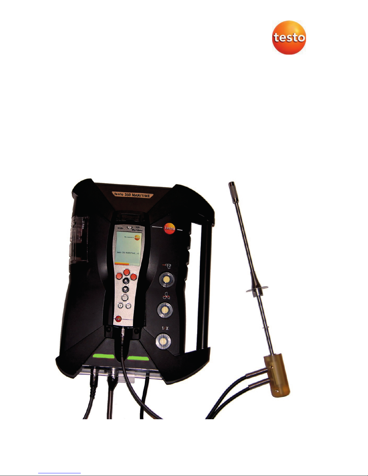
testo 350 MARITIME V2 · Flue gas analyzer
Instruction manual
Page 2

2
Page 3

1 Contents
3
1 Contents
1 Contents ...................................................................................................3
2 Safety and the environment....................................................................6
2.1. About this document........................................................................6
2.2. Ensure safety...................................................................................7
2.3. Hazard warnings..............................................................................8
2.4. Protecting the environment............................................................11
3 Specifications ........................................................................................12
3.1. Use ................................................................................................12
3.2. Technical data ...............................................................................14
3.2.1. Declaration of Conformity ..............................................................................14
3.2.2. Measuring ranges and accuracies .................................................................15
3.2.3. Recommended test gas concentrations ......................................................... 16
3.2.4. Other instrument data.................................................................................... 16
4 Product description...............................................................................18
4.1. Scope of delivery ...........................................................................18
4.2. Control unit ....................................................................................19
4.2.1. Overview........................................................................................................19
4.2.2. Keyboard .......................................................................................................20
4.2.3. Display........................................................................................................... 21
4.2.4. Connections / interfaces ................................................................................22
4.2.5. Menu guide for control unit ............................................................................22
4.3. Measuring box...............................................................................23
4.3.1. Overview........................................................................................................23
4.3.2. Status display ................................................................................................24
4.3.3. Connections / interfaces ................................................................................ 25
4.3.4. Functions / instrument options .......................................................................26
4.3.5. Menu guide for measuring box.......................................................................26
4.4. Flue gas probe...............................................................................28
4.4.1. Overview........................................................................................................28
5 First steps ..............................................................................................29
5.1. Commissioning ..............................................................................29
5.2. Getting to know the product...........................................................29
5.2.1. Mains unit, batteries/rechargeable batteries...................................................29
5.2.1.1. Recharging the rechargeable battery for the control unit .................30
5.2.1.2. Charging the rechargeable battery for the measuring box ...............30
5.2.1.3. Battery care.....................................................................................31
5.2.1.4. Mains operation............................................................................... 31
5.2.2. Connecting probes / sensors .........................................................................32
5.2.3. Occupying the trigger input............................................................................32
5.2.4. Connecting system components .................................................................... 33
5.2.4.1. Connection via contact strip.............................................................33
5.2.4.2. Connection to a bus system via data bus cable (accessory)............ 33
Page 4

1 Contents
4
5.2.5. Switching on .................................................................................................. 35
5.2.6. Calling up the function ................................................................................... 36
5.2.7. Entering values.............................................................................................. 36
5.2.8. Printing / saving data ..................................................................................... 38
5.2.9. Search for boxes ...........................................................................................38
5.2.10. Confirming an error message ........................................................................38
5.2.11. Switching off .................................................................................................. 38
5.3. Folder............................................................................................ 39
5.4. Measurement records................................................................... 41
5.5. Instrument diagnosis..................................................................... 42
5.5.1. Error diagnosis ..............................................................................................42
5.5.2. Gas path check.............................................................................................. 42
5.5.3. Sensor diagnosis........................................................................................... 43
5.5.4. Device information......................................................................................... 43
6 Using the product ................................................................................. 43
6.1. Performing settings....................................................................... 43
6.1.1. Assigning the right hand function key ............................................................ 43
6.1.2. Instrument settings ........................................................................................ 43
6.1.2.1. Measurement view .......................................................................... 43
6.1.2.2. Units................................................................................................ 45
6.1.2.3. Date / time....................................................................................... 46
6.1.2.4. Power options..................................................................................46
6.1.2.5. Display brightness ........................................................................... 46
6.1.2.6. Printer .............................................................................................47
6.1.2.7. Language ........................................................................................ 47
6.1.2.8. Password protection........................................................................ 47
6.1.2.9. Analog input .................................................................................... 48
6.1.2.10. Data bus.......................................................................................... 49
6.1.3. Fuels.............................................................................................................. 49
6.1.4. Sensor settings.............................................................................................. 50
6.1.4.1. Sensor protection ............................................................................ 50
6.1.4.2. Calibration / adjustment................................................................... 51
6.1.4.3. Calibration data ............................................................................... 53
6.1.4.4. Negative values............................................................................... 54
6.1.5. Programs....................................................................................................... 54
6.2. Measuring ..................................................................................... 56
6.2.1. Preparing for measurement ........................................................................... 56
6.2.2. Position flue gas probe .................................................................................. 58
6.2.2.1. Flue gas flow with hot spot characteristics....................................... 58
6.2.2.2. Flue gas flow without hot spot characteristics.................................. 58
6.2.3. Attachment options for the flue gas probe...................................................... 59
6.2.3.1. Using the probe stop ....................................................................... 59
6.2.3.2. Using the welded pipe..................................................................... 60
6.2.4. Vibrations ......................................................................................................60
6.2.5. Flue gas measurement.................................................................................. 61
6.2.6. Differential pressure measurement (determining the pressure in the flue gas
duct) ..............................................................................................................63
6.2.7. EMDS measurement ..................................................................................... 64
6.3. Analog outputs.............................................................................. 65
Page 5

1 Contents
5
7
Maintaining the product........................................................................67
7.1. Changing the rechargeable battery ...............................................67
7.2. Cleaning the flue gas analyser ......................................................67
7.3. Changing / retrofitting sensors.......................................................68
7.4. Recalibrating sensors....................................................................70
7.5. Cleaning the flue gas probe...........................................................70
7.6. Changing the thermocouple...........................................................71
7.7. Condensate container ...................................................................72
7.8. Checking / replacing the dirt filter ..................................................73
7.9. Cleaning / replacing the pump .......................................................75
7.9.1. Cleaning the main gas pump .........................................................................75
7.9.2. Changing the main gas pump ........................................................................76
7.9.3. Changing the condensate pump .................................................................... 77
7.9.4. Replacing the motor of the condensate pump................................................ 78
7.10. Replacing the filtration non-woven in the gas cooler .....................80
7.11. Recommended maintenance cycles..............................................81
8 Tips and assistance...............................................................................82
8.1. Questions and answers.................................................................82
8.2. Accessories and spare parts .........................................................84
8.3. Updating the instrument software..................................................86
9 Appendix ................................................................................................88
9.1. Cross-sensitivities..........................................................................88
9.2. Recommendation for emissions measurements over an extended
period of time.................................................................................89
9.3. Fuel parameters ............................................................................90
9.4. Certificates/Type Approvals...........................................................91
Page 6
2 Safety and the environment
6
2 Safety and the environment
2.1. About this document
This document describes the testo 350 MARITIME.
Use
> Please read this documentation through carefully and
familiarize yourself with the product before putting it to use. Pay
particular attention to the safety instructions and warning advice
in order to prevent injuries and damage to the products.
> Keep this document to hand so that you can refer to it when
necessary.
> Hand this documentation on to any subsequent users of the
product.
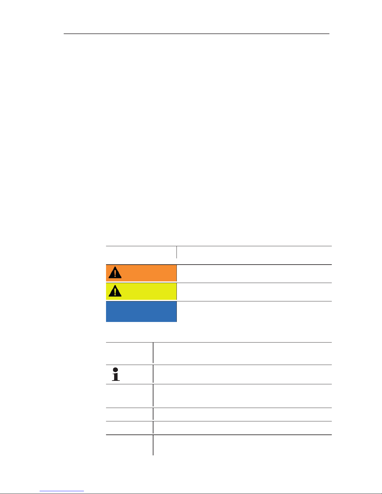
Warnings
Always pay attention to information that is marked by the following
warnings with warning pictograms. Implement the specified
precautionary measures.
Representation Explanation
WARNING Indicates potential serious injuries
CAUTION
indicates potential minor injuries
NOTICE
indicates circumstances that may lead to
damage to the products
Symbols and writing standards
Representation
Explanation
Note: Basic or further information.
1. ...
2. ...
Action: more steps, the sequence must be followed.
> ... Action: a step or an optional step.
- ... Result of an action.
Menu
Elements of the instrument, the instrument displays
or the program interface.
Page 7

2 Safety and the environment
7
[OK]
Control keys of the instrument or buttons of the
program interface.
... | ... Functions/paths within a menu.
“...” Example entries
2.2. Ensure safety
> Only operate the product properly, for its intended purpose and
within the parameters specified in the technical data. Do not
use any force.
> Do not operate the instrument if there are signs of damage at
the housing, mains unit or feed lines.
> Do not perform contact measurements on non-insulated, live
parts.
> Do not store the product together with solvents. Do not use any
desiccants.
> Carry out only the maintenance and repair work on this
instrument that is described in the documentation. Follow the
prescribed steps exactly. Use only original spare parts
from Testo.
> Any further or additional work must only be carried out by
authorised personnel. Testo will otherwise refuse to accept
responsibility for the proper functioning of the measuring
instrument after repair and for the validity of certifications.
> The measuring instrument should not be installed in locations
with extremely high vibrations.
> Before use: Pay strict attention to the installation information for
the flue gas probe.
> To prevent damage to the instrument, engine system or
persons due to powerful vibration of the flue gas duct, the gas
sampling probe must be attached in such a way that it is
impossible for it to come loose. The probe must be positioned
so that any parts that come loose cannot get into the machine
system's moving components.
> Once measurement has been completed, remove the gas
sampling probe from the flue gas duct and close the sampling
point.
> Temperatures given on probes/sensors relate only to the
measuring range of the sensors. Do not expose handles and
feed lines to any temperatures in excess of 70 °C unless they
are expressly permitted for higher temperatures.
> Do not operate the measuring instrument in the transport case.
Page 8

2 Safety and the environment
8
2.3. Hazard warnings
Description Man
Hazard
to
system
Instru
ment
Power supply
Disconnecting the protective conductor by
any means inside or outside the device is
prohibited! Using the identification plate,
check that the type, line voltage and
power correspond to the actual data.
XX
Disposing of sensors
The sensors contain small quantities of
concentrated acids. Dispose of as
hazardous waste!
Hazardous when
handled inappropriately!
X
Storing the measuring instrument
Never store the measuring instrument in
rooms together with solvents. Danger of
destruction of the sensors! Ensure that the
permissible storage, transport end
operating temperatures are observed.
X
Rechargeable battery
Fully charge the rechargeable battery
before the first measurement and after
several days of disuse. Recharge the
rechargeable battery every 4 weeks
during long periods of disuse. The testo
battery block for the control unit must be
inserted so that the marking is visible on
the upper side. Otherwise, there is the risk
of short circuit and reverse polarity if the
insulating foil is damaged
X
Operating the flue gas probe
Be careful when removing the probe from
the flue gas duct, because the probe will
be hot!
X
Page 9

2 Safety and the environment
9
Description Man
Hazard
to
system
Instru
ment
Condensate outlet
Aggressive condensate (acid) escapes
from the condensate outlet. If there is no
appropriate drainage facility (e.g. hose),
this constitutes a hazard to materials and
user!
XX
Service and maintenance
The mains plug must always be pulled out
before opening the housing. Danger of
electric shock! Only authorised persons
may carry out work inside the instrument!
XXX
Non-permissible measurements
This instrument must NOT be used to
measure explosive or flammable gas
mixtures and gases that form flammable
mixtures when exposed to atmospheric
air!
X
Test gas pressure
A maximum of 50 mbar is permissible.
Higher pressures run the risk of
destroying the gas sensors! In addition,
test gas must only be used in well
ventilated rooms!
XX
Cleaning the instruments
Prevent the penetration of water into the
instrument at all costs!
X
Differential pressure sensor
When taking measurements, observe the
permissible measuring ranges. Exceeding
the measuring range will result in
destruction of the sensor!
X
Condensation
Avoid exposing the instrument and the
instrument electronics to condensation.
X
Measuring in closed rooms
Ensure that there is adequate ventilation.
Danger of poisoning!
X
Page 10

2 Safety and the environment
10
Description Man
Hazard
to
system
Instru
ment
Entire system
Do not connect any part of the system to
live parts for measurement. Danger of
electric shock!
X
Protect system against overvoltage. X
CO measurement
Ensure that there is adequate ventilation
when measuring toxic gases
(CO). Danger of poisoning!
X
Power supply to the entire system
Always ensure that the entire system is
supplied with sufficient power (new or
charged batteries, mains unit). Danger of
the entire system becoming unstable.
X
EMC
Increased electromagnetic interference
can result in readings deviating from the
standard specifications. Danger if the
analog/switching outputs are connected.
The mains plug must have a protective
earth conductor connected. The
temperature display with control unit and
separate probe can jump by up to 2°C in
the case of a thermocouple with earth
contact in connection with a switchedmode power supply.
XX
Page 11
2 Safety and the environment
11
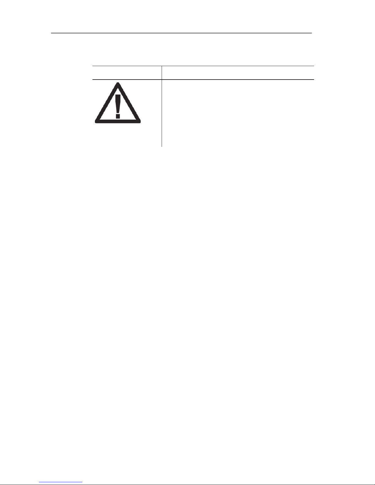
Safety related symbols on the instrument
Representation Explanation
If the product is not used in strict compliance
with this documentation, the intended
protection may be impaired.
> Operate the product only as described in
this documentation.
> Please consult your dealer or the
manufacturer if in doubt.
2.4. Protecting the environment
> Dispose of faulty rechargeable batteries/spent batteries in
accordance with the valid legal specifications.
> At the end of its useful life, send the product to the separate
collection for electric and electronic devices (observe local
regulations) or return the product to Testo for disposal.
Page 12

3 Specifications
12
3 Specifications
3.1. Use
Do not use the testo 350 MARITIME for continuous flue gas
measurements, i.e. the sensors must be regularly rinsed with fresh
air. Recommended measurement periods and rinse phases, see
Recommendation for emissions measurements over an extended
period of time, page 89.The testo 350 MARITIME is a portable
flue gas analyser, which can be used as a system component
within a complete monitoring system to measure flue gas
emissions from marine diesel engines in accordance with
MARPOL 73/78 Annex VI and NOx Technical Code 2008
(MEPC.177(58)). In order to fully comply with the on-board
detection procedure of the “Direct Measurement and
Monitoring Method” MARPOL 73/78 Annex VI and NOx
Technical Code 2008 (MEPC.177(58)), additional parameters
must be recorded.
The testo 350 MARITIME has been designed for the following
applications:
• The testo 350 MARITIME can be used as a system component
to measure the gaseous flue gas concentrations of O
2
, CO,
CO
2
, NOx and SO2for the following procedures:
• for periodical examinations and for intermediary
examinations for direct measurement and monitoring on
board
• as a component for a simplified test and measuring method
(HC must be measured separately
• testing the NOx limits specified in MARPOL Annex VI for official
NOx monitoring measurements on board.
• NOx measurement as proof in regional special zones, e.g. as
proof of NOx reduction for NOx tax in Norway
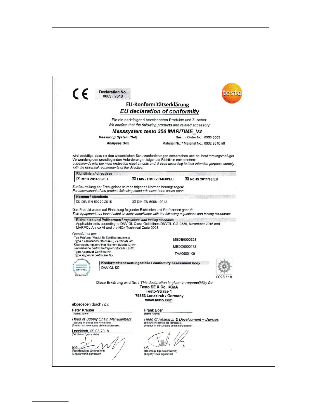
The flue gas analyser testo 350 MARITIME is certified by
DNV GL for measuring gaseous flue gas components as a
system component (e.g. for the “direct measurement and
monitoring” on board procedure, and for simplified
measurement procedures).
Other system components required in accordance with
NOx Technical Code for the “direct measurement and
monitoring” on board procedure are not included in this
certification!
Page 13

3 Specifications
13
Prior authorisation from the respective flag state is
required in order to use a monitoring system and its
measurement results.
The testo 350 MARITIME V2 is not suitable for measuring
SO2 exhaust gas concentrations that correspond to sulfur
concentrations below 0.5%.
Page 14
3 Specifications
14
3.2. Technical data
3.2.1. Declaration of Conformity
Page 15

3 Specifications
15
3.2.2. Measuring ranges and accuracies
Measuring box
Measurement
parameter
Measurement
range
Tolerance
°C, flue gas -40 to +1000 °C max. ± 5 K
O
2
0 to 25vol.% according to Marpol,
CO 0 to 3000 ppm Annex VI or NOx
NO 0 to 3000 ppm Technical Code 2008
NO
2
0 to 500 ppm
SO
2
100 to 3000 ppm
CO2(IR) 0 to 40Vol.%
P
abs
600 to 1150 hPa ± 5 hPa at 22 °C
± 10 hPa at -5 to +45 °C
Measurement
parameter
Measurement
range
Resolution
Differential
pressure
-200 to 200 hPa 0.1 hPa
NTC (permanently
installed)
-20 to 50°C 0.1°C
Absolute pressure 600 to 1150 hPa 1 hPa
Type K (NiCr-Ni) -200 to 1370°C 0.1°C
Type S (Pt10RhPt)
0 to 1760°C 1°C
Measurement
parameter
Accuracy Response
time
Differential
pressure
± 0.5 hPa (-49.9 to 49.9 hPa)
±1.5% of reading (rest of
range)
-
Absolute pressure ±10 hPa -
Type K (NiCr-Ni)
±0.4°C (-100 to 200°C)
±1°C (rest of range)
-
Page 16

3 Specifications
16
Measurement
parameter
Accuracy Response
time
Type S (Pt10RhPt)
±1°C (0 to 1760°C)
-
3.2.3. Recommended test gas concentrations
Measurement
parameter
Measurement range
CO 500 ppm (in N2)
CO
2
15% (in N2)
NO 1800 ppm (in N2)
NO2 100 ppm (in synthetic air)
SO2 1000 ppm (in N2)
3.2.4. Other instrument data
Control unit
Feature Values
Power supply • via Li-ion rechargeable battery
• via measuring box
• via mains adapter
Battery charge time 7h (via mains adapter)
14h (via CAN interface)
Rechargeable
battery life
approx. 5 hrs (display switched on)
Memory 250,000 readings
Housing material ABS_UL_94V0_black
Weight 440g
Display Graphic colour display, 240 x 320 pixels
Dimensions 88 x 38 x 220mm
Page 17

3 Specifications
17
Measuring box
Feature Values
Power supply • via Li-ion rechargeable battery
• 100...240V/0.8...0.4A
Battery charge time <6h
Rechargeable
battery life
2.5 hrs (with gas cooler and IR module)
Dimensions 330 x 128 x 438mm
Housing ABS URL 94V0
Weight 4800g (completely assembled)
Memory 250,000 readings
Flue gas
overpressure
max 50 hPa
Underpressure max. 300 hPa
Pump volumetric
flow rate
1 l/min (controlled), standard litre ±0.1 l/min
Hose length max. 5m
Diluting gas Fresh air or nitrogen
Flue gas dust load max. 20g/m
3
Humidity load max. 70°Ctd at measuring input
USB interface USB 2.0
Trigger input Voltage: 5 to 12 V (falling or rising flank)
Pulse width: >1 s
Load: 5V/max. 5 mA, 12 V/max. 40mA
Feature Values
Ambient
temperature
-5°C to 45°C
short-term (max. 5min.): up to 80°C by
radiated heat (e.g. heat radiation from a hot
flue gas duct)
Ambient pressure 600 to 1100mbar (abs.)
Ambient humidity 5 to 95%RH
Storage and
transport
temperature
-20 to 50°C
Protection class IP40
Page 18

4 Product description
18
4 Product description
4.1. Scope of delivery
• testo 350 MARITIME control unit
• testo 350 MARITIME flue gas analyser, equipped with:
ƕ O
2
, CO, CO2(IR), NO, NO2and SO2sensor incl. differential
pressure sensor
ƕ Temperature probe input Type K NiCr-Ni and Type S
Pt10Rh-Pt
ƕ Testo data bus connection
ƕ Rechargeable battery
ƕ Integrated combustion air probe (NTC)
ƕ Trigger input
ƕ Measurement data memory
ƕ USB interface
ƕ Gas processing
ƕ Measurement range extension for single slot (only for SO
2
)
ƕ Fresh air valve
• Connecting cable (5m) between flue gas analyser and control
unit
• Flue gas probe for industrial engines with probe shaft prefilter
ƕ 335mm immersion depth incl. probe stop and heat
protection plate,
ƕ Tmax 1000°C,
ƕ Special hose for NO2/SO2 measurements, length 4m, incl.
thermocouple for flue gas temperature measurement (NiCrNi, length 400mm, Tmax. +1000°C) with 4m connection
cable and additional temperature protection
• Printer
• Mains cable
• Humidity measuring instrument testo 610
• CO2 calibration kit including service adapter for applying
calibration gas
• Silicone hose, ø 4mm, length: 5m
• Hose connector
• Spare filter (optional)
• Thermal paper for printer
• Instruction manual
• Calibration report
Page 19
4 Product description
19
• EC declaration of conformity
• Robust protective case with trolley function
4.2. Control unit
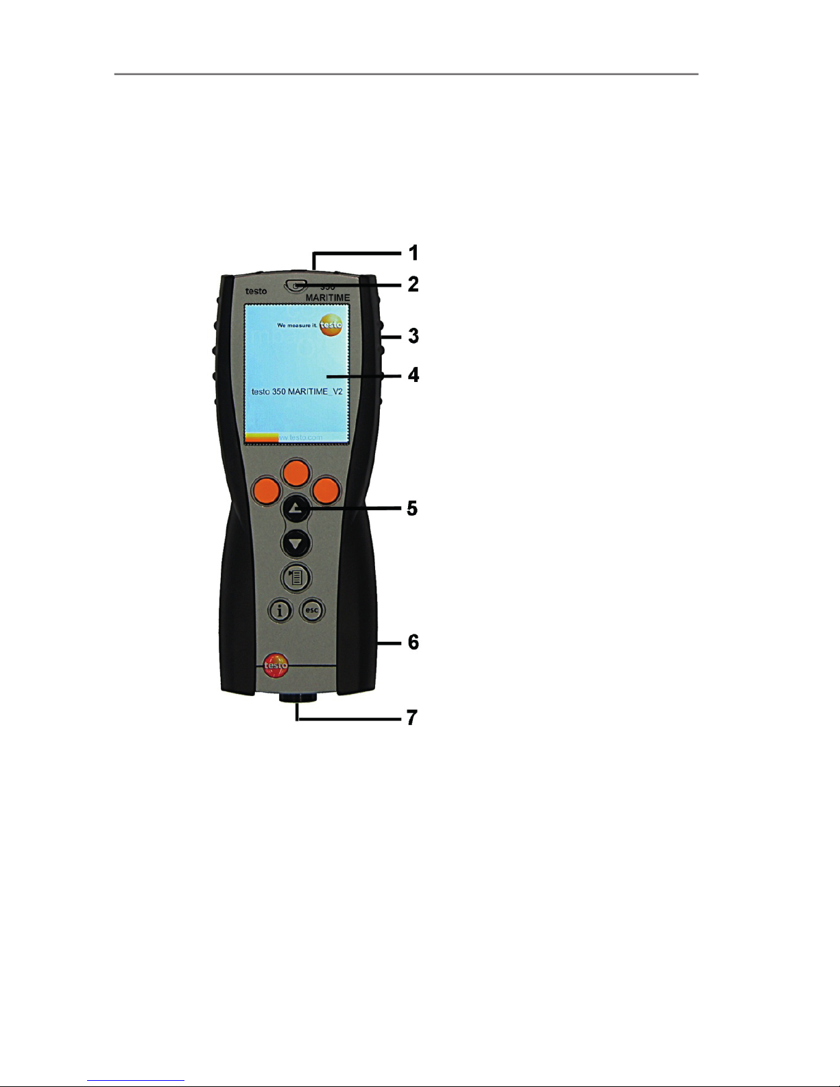
4.2.1. Overview
1 IrDA interface
2 Switch on / off
Page 20
4 Product description
20
3 Magnetic holder (on rear)
WARNING
Magnetic field
May be harmful to those with pacemakers.
> Keep a minimum distance of 15 cm between pacemaker and
instrument.
ATTENTION
Magnetic field
Damage to other devices!
> Keep a safe distance away from products which could be
damaged by the effects of magnetism (e.g. monitors,
computers or credit cards).
4 Display
5 Keyboard
6 Contact strip for connection to the measuring box (on rear)
7 Interfaces: USB 2.0, charger, Testo data bus
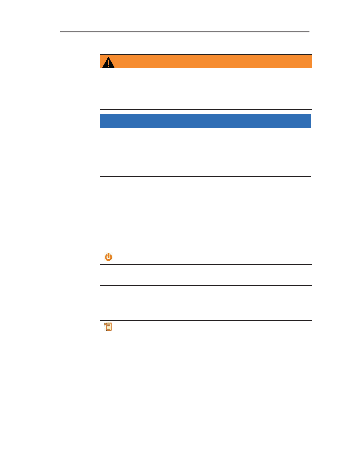
4.2.2. Keyboard
Button Functions
[]
Switch measuring instrument on / off
[OK]
Example
Function key (orange, 3x), relevant function is shown on
the display
>Ÿ@ Scroll up, increase value
>ź@ Scroll down, reduce value
[esc] Back, cancel function
[]
Open main menu
[ i ] Open menu Instrument diagnosis
Page 21
4 Product description
21
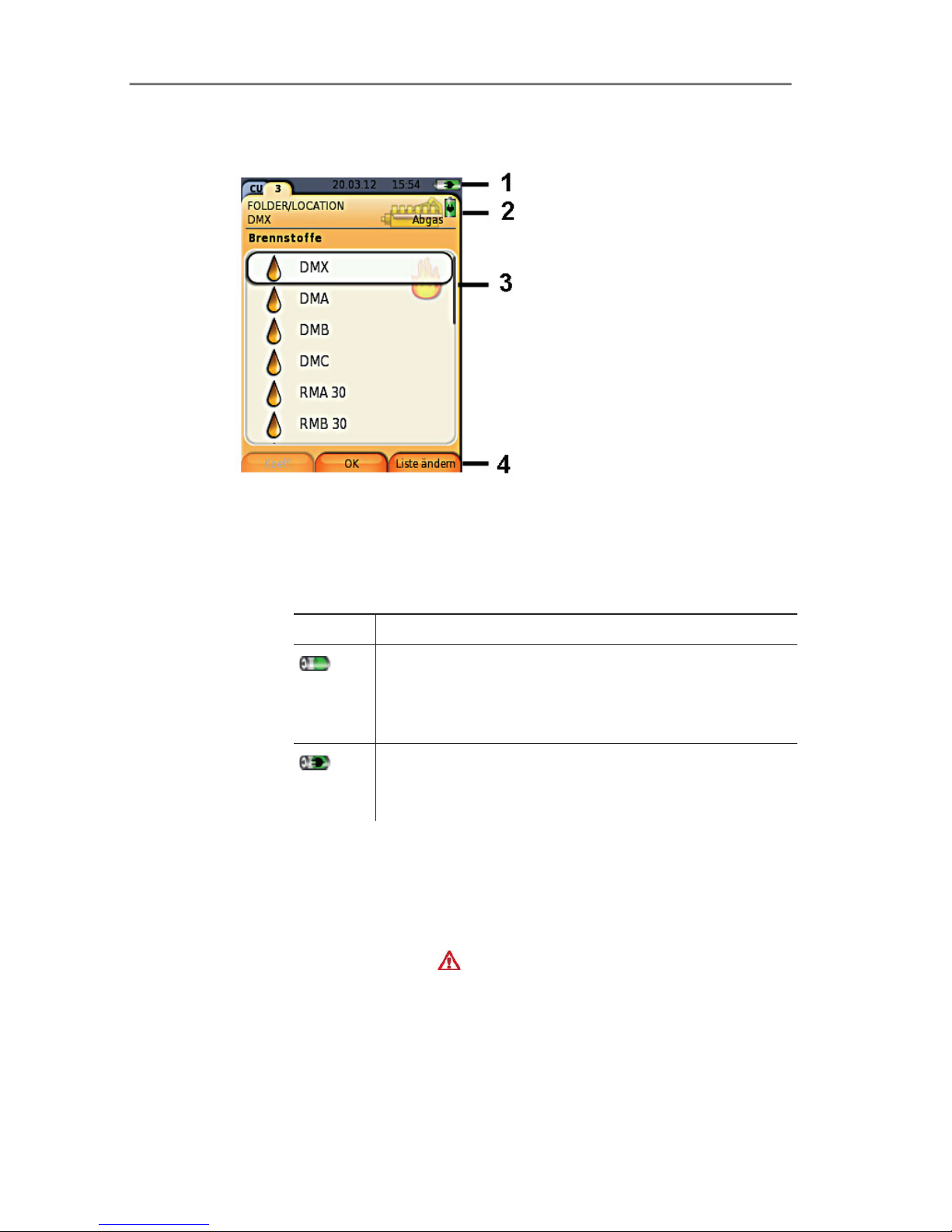
4.2.3. Display
1 Status bar (dark grey background):
• Display of date and time (valid for control unit and
measuring box).
• Display of status, power supply and remaining rechargeable
battery capacity (valid for control unit):
Icon Feature
Battery operation
Indication of remaining capacity of the
rechargeable battery by colour and fill level of the
battery icon (green = 20-100%, red = < 20%)
Mains operation
Indication of remaining capacity of rechargeable
battery: see above
2 Tabs and tab info field:
• Tabs: Display of measuring system components (CU =
control unit, 2, 3, etc. = measuring boxes, analog output
box) connected to the control unit.
The tabs provide access to the individual components.
Warning symbol:
- Red frame, red symbol / white background:
Display of instrument errors in the instrument diagnosis
menu, otherwise: Instrument designation.
- Black frame, black symbol / yellow background:
Information message (symbol is displayed alternately with
the instrument designation).
Page 22
4 Product description
22
- Yellow frame, yellow symbol / red background:
Warning (symbol is displayed alternately with the
instrument designation).
• Information field on tab (only in the tabs of measuring
boxes): Indication of selected folder/location, selected fuel,
selected application, status of power supply and remaining
rechargeable battery capacity (valid for measuring box,
symbols such as display for control unit, see above).
3 Selection field for functions (selected function appears against a
white background, unavailable functions are identified by grey
characters) or display of readings.
4 Function display for function keys.
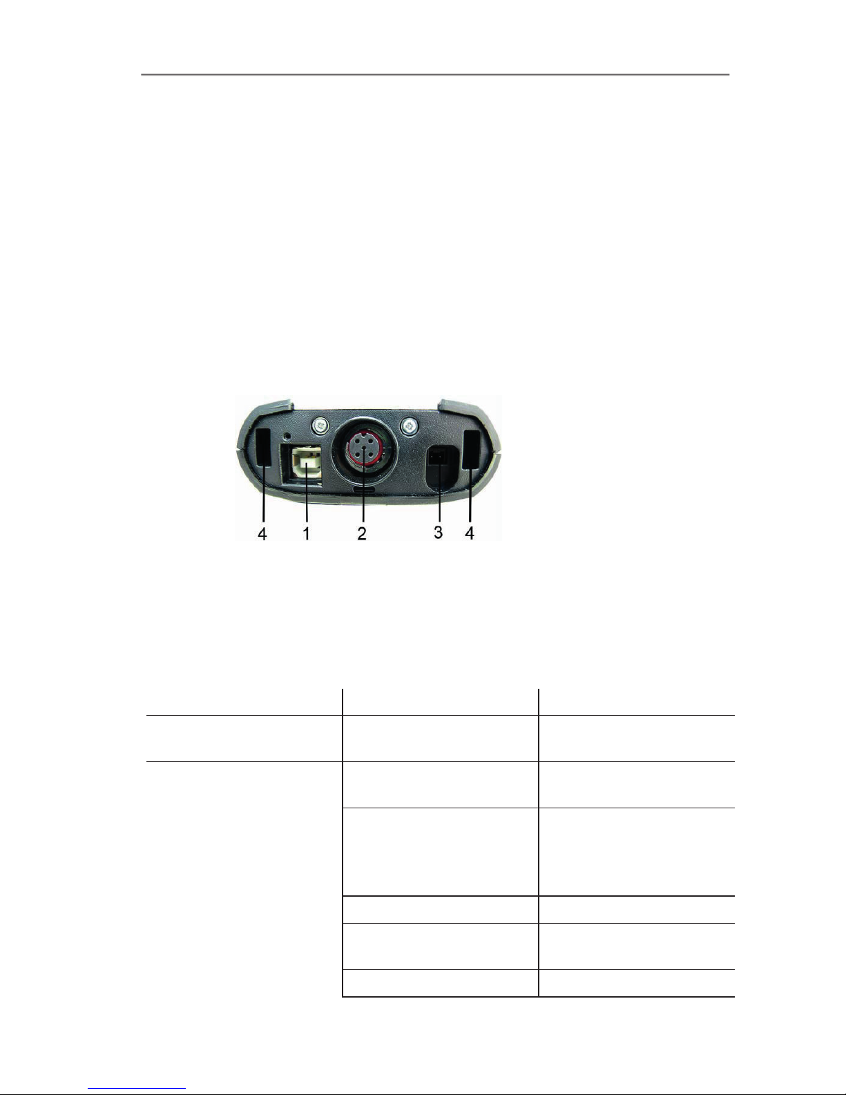
4.2.4. Connections / interfaces
1 USB 2.0
2 Testo data bus
3 Connecting socket for mains unit 0554 1094
4 Guide groove for locking with the measuring box
4.2.5. Menu guide for control unit
Main menu Menu Description
Measurement records - Display of saved
measurement records
Device settings Date/Time Set date, time, time
format:
Power Options Automatic instrument
shut-down on / off
Display backlight in
battery operation on / off
Display brightness Set display brightness
Printer Select printer, enter print
text
Language Set instrument language
Page 23
4 Product description
23
Main menu Menu Description
Password protection Change password
Data bus Display of bus address,
enter bus rate
Instrument diagnosis Error diagnosis Display of errors present
Device information Display of device
information
Search for boxes - Set up connection to
measuring boxes
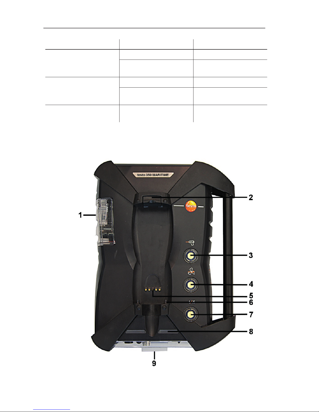
4.3. Measuring box
4.3.1. Overview
Page 24
4 Product description
24
1 Condensate container
2 Locking/unlocking button for control unit
3 Measuring gas particle filter
4 Fresh air inlet filter
5 Contact bar for connection to control unit
6 Guide pins for locking with control unit
7 Dilution air filter
8 Status display
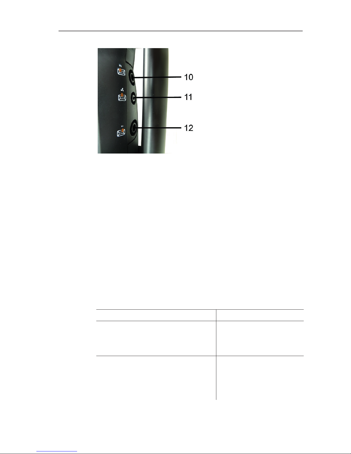
9 Full-visibility tab for labelling/marking
10 Gas outlet 1
11 Fresh air inlet
12 Gas outlet 2
4.3.2. Status display
The status display shows the operating status of the measuring
box:
Display Status
green / permanent (measuring box
switched on)
Mains operation or
rechargeable battery
operation / rechargeable
battery fully charged
red / flashing (measuring box switched
on)
• Rechargeable battery
operation / residual
rechargeable battery
capacity < 20%
• Other system failure
Page 25
4 Product description
25
Display Status
green / flashing (measuring box
switched off)
Rechargeable battery or
trickle charging
green / permanent (measuring box
switched off)
Rechargeable battery fully
charged,
green, red / alternately flashing Update mode active
green / yellow alternately flashing
(green is on longer)
Instrument is in the switchon phase
yellow / green alternately flashing
(yellow is on longer)
Instrument is in the switchoff phase
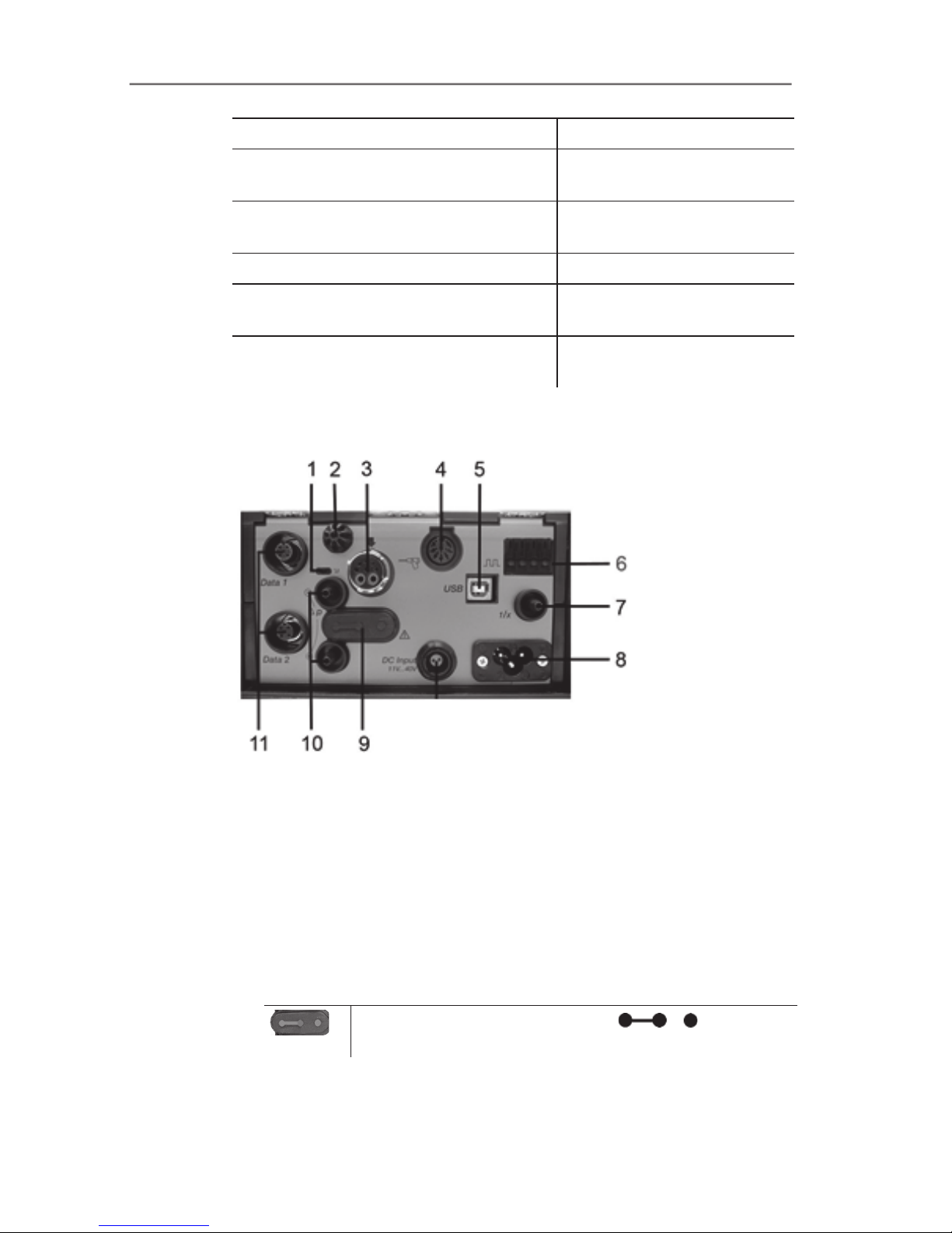
4.3.3. Connections / interfaces
1 Data bus termination slide switch
2 Sensor for combustion air temperature (VT)
3 Flue gas probe
4 Sensor input
5 USB 2.0
6 Trigger input
7 Dilution air inlet for measurement range extension
8 Mains connection 100 to 240V AC, 50-60Hz
9 Gas channel access cover cap (only for servicing purposes)
Plugged in cover cap: Position ( ) must not
be changed!
10 Pressure ports p+ and p11 Testo data bus
Page 26

4 Product description
26
4.3.4. Functions / instrument options
Some functions are available as optional extras. The functions your
measuring box is equipped with (condition as delivered) can be
read on the identification plate on the bottom of the measuring box.
Imprint Description
CO, NO, NO2, SO2,
O
2
, CO2(IR)
The sensor of the specified type is plugged in
SG Special main gas pump for long-term
measurement
1/x Measurement range extension (SO2 sensor)
GP Gas preparation, by means of reduced and
constant measuring gas dew point
temperature for higher measuring accuracy
4.3.5. Menu guide for measuring box
Main menu Menu Description
Measurementoptions - Select measurement type
• Flue gas
• Differential pressure
• EMDS
• Prog. 1
• Prog. 2
Folder - Create and manage folders
and locations
Fuels - Select and configure fuel
Measurement records - Display and manage
measurement records
Device settings Measurement view Configure display, set
measurement parameters
and units
Units Set units for display
variables
Date/Time Set date, time, time format:
Power Options
Set automatic instrument
shut-down and switch off
display backlight during
rechargeable battery
operation
Page 27

4 Product description
27
Main menu Menu Description
Display brightness Set display brightness
Printer Select printer, enter print
text
Language Set instrument language
Password protection Change password
Analog input Configure analog input
Data bus Display of bus address,
enter bus rate
Sensor settings Sensor protection Set safety cut-out
Recalibration Carry out calibration /
adjustment:
ppm counter Consumption display for the
sensors
Calibration data Calibration data display
Negative values Select negative values
display
Programs - Configure and activate
measuring programs
Instrument diagnosis Error diagnosis Display of errors present
Gas path check Carry out tightness test
Sensor diagnosis Carry out sensor diagnosis
Device information Display of device information
Page 28
4 Product description
28
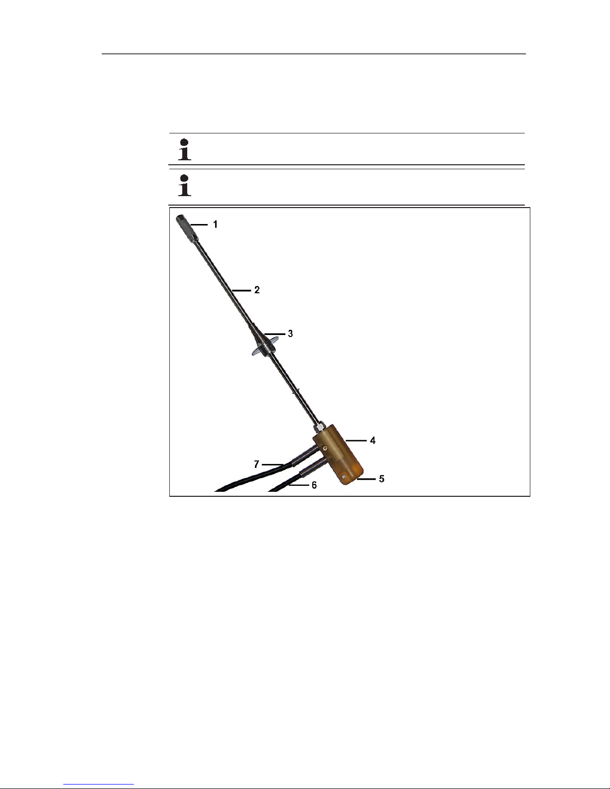
4.4. Flue gas probe
4.4.1. Overview
Follow the safety instructions,
Before use: Pay strict attention to the installation
information for the flue gas probe,
1 Prefilter
2 Probe shaft
3 Probe shaft stop
4 Probe handle with connections for probe shaft and gas tubes /
thermocouple
5 Thermocouple
6 Gas tube
7 Overpressure outlet with locking clip
Page 29

5 First steps
29
5 First steps
5.1. Commissioning
Control unit
The control unit has a permanently installed rechargeable battery.
> Remove the protective film from the display.
> Charge the rechargeable battery fully before using the control
unit.
Measuring box
The measuring box is supplied with a rechargeable battery already
fitted.
> Charge the rechargeable battery fully before using the
measuring box.
For longer measurements, we recommend using via the
integrated mains unit.
In order to guarantee the security of the data connection, it
is recommended to connect the control unit and the flue
gas analyser using the connecting cable (item no.
0449 0042 included in the kit).
5.2. Getting to know the product
5.2.1. Mains unit, batteries/rechargeable batteries
In case of longer interruption of the power supply to the
control unit (e.g. rechargeable battery empty) the settings
for date / time will be lost.
If the power supply to the flue gas analyser is interrupted
for a long time (empty rechargeable battery pack), it takes
approx. 2 hours before an accurate NOx measurement
can be carried out.
Page 30

5 First steps
30
5.2.1.1. Recharging the rechargeable battery for the control unit
The rechargeable battery can only be charged at an ambient
temperature of ±0 to +35°C. If the rechargeable battery has been
completely discharged, the charging time at room temperature will
take about 7h (charging with mains adapter) or approx. 14h
(charging via Testo data bus).
Charging via mains unit (item no. 0554 1094)
㾐 The control unit is switched off.
1. Connect the plug of the mains unit to the mains unit socket on
the control unit.
2. Connect the mains plug of the mains unit to a mains socket.
- The charging process starts. The charge status will be shown
on the display.
- Once the rechargeable battery has been charged, the
instrument will automatically change to trickle charge.
Charging via measuring box
㾐 Control unit is locked to measuring box or is connected via the
Testo data bus cable.
㾐 The measuring box is supplied via the mains unit.
During operation with low charge power or in switched off state.
5.2.1.2. Charging the rechargeable battery for the measuring box
The rechargeable battery pack can only be charged at an ambient
temperature of ±0 to +35°C. If the rechargeable battery has been
discharged completely, the charging time at room temperature is
approx. 6h.
㾐 The measuring box is switched off.
> Connect mains cable to measuring box and mains socket.
- Charging will start, the fan may come on automatically. The
status LEDs lights green while the rechargeable battery is being
charged.
- Once the rechargeable battery has been charged, the
instrument will automatically change to trickle charge. The
charging status of the measuring box is shown on the control
unit display.
Page 31

5 First steps
31
5.2.1.3. Battery care
> Do not fully exhaust rechargeable batteries.
> Store rechargeable batteries only in charged condition and at
low temperatures, but not below 0°C.
> For longer breaks, you should discharge and recharge the
batteries every 3-4 months. Trickle charging should not exceed
2 days.
5.2.1.4. Mains operation
In case of danger, the instrument must be disconnected from the
electric power supply by simply pulling out the mains cable.
> Always position the instrument so that the power supply plug
can be easily reached.
Control unit
1. Connect the plug of the mains unit to the mains unit socket on
the control unit.
2. Connect the mains plug of the mains unit to a mains socket.
- The control unit is powered by the mains unit.
- If the control unit is switched off, the rechargeable battery
charging process will start automatically. Switching the control
unit on has the effect of stopping battery charging and the
control unit being powered via the mains unit.
Measuring box via internal mains unit
> Connect the mains cable to the measuring box and a mains
socket.
- The measuring box is powered via the internal mains unit.
- If the measuring box is switched off, the rechargeable battery
charging process will start automatically. Battery charging stops
when the flue gas analyser is switched on via the control unit.
Page 32

5 First steps
32
5.2.2. Connecting probes / sensors
Sensor detection takes place during the activation
process: Sensors that are required must always be
connected before the flue gas analyser is switched on,
or the flue gas analyser must be switched off and then
on again after a sensor change, so that the correct
sensor data can be read.
> Connect the supplied flue gas probe for industrial engines to the
corresponding connection.
- Measurement of the flue gas temperature is carried out via the
thermocouple at the tip of the flue gas probe inside the probe
filter.
5.2.3. Occupying the trigger input
The trigger input can be used as a criterion to either start or stop
(ascending or descending flank) measuring programs.
> Occupying the trigger input, with external voltage supply
(5...12 V):
> Occupying the trigger input, with supply via instrument voltage
(12 V):
In case of supply via instrument voltage the flue gas
analyser can only be started via the trigger input from
switched off state when the mains plug is plugged in.
Page 33

5 First steps
33
5.2.4. Connecting system components
5.2.4.1. Connection via contact strip
The control unit can be plugged onto the measuring box.
1. Insert the guide groove on the bottom of the control unit into the
guide pins of the measuring box.
2. Press the control unit against the measuring box until the
locking/unlocking button noticeably clicks into place twice.
To protect the display (e.g. during transport) the control unit
can also be inserted with the back facing up, however, in
this case there is no connection to the measuring box.
5.2.4.2. Connection to a bus system via data bus cable (accessory)
The individual components (e.g. control unit to measuring box or
measuring box to measuring box) can be connected to a bus
system using the Testo data bus cable.
Prior to commissioning a bus system, the bus address and
the data rate of the connected components must be
changed.
Before the components are joined up to a bus system, each
component must be configured separately via the control unit.
Page 34

5 First steps
34
Call up function:
[]ĺDevice settings ĺ[OK] ĺData bus ĺ[OK].
Bus address
The bus address of each component connected to the Testo data
bus must be unique. The bus address of the connected component
can be changed, if this should be necessary.
1. Bus Address ĺ [Edit].
2. Setting a new bus address: [], [], [Ż], [Ź].
3. Confirm the entry: [OK].
Data rate
Select the appropriate data rate, depending on the number of
connected components in a system,
• Control unit with a measuring box: 500 kbit/s
• All other systems: 50 kbit/s
>SelectData rate 500 kbit/s or 50 kbit/s : [], [], ĺ [Edit]
ĺ []or [ESC].
If several measuring boxes are connected to the control
unit, only the measurement data from one measuring box
can be displayed at a time, or only one measuring box can
be activated respectively. This is accomplished by selecting
the measuring box, see Search for boxes, page 38.
> Connect the data bus cable to the data bus interfaces.
Please observe the following points when setting up a connection
via data bus cable:
• Use only Testo data bus cables.
• Do not route data bus cables anywhere near electric power
cables.
• Ensure sufficient power supply by supplying each measuring
box with line voltage.
• The cables should ideally be plugged in before the system is
switched on. Connecting during operation (hot plugging) is
possible, however, depending on the combination the system
may need to be switched off and on again.
• The connection cannot be disconnected under load.
•
Page 35

5 First steps
35
Data bus subscribers: max. 3 measuring boxes in one data bus
system.
• Cable length: max. 100 m between control unit and measuring
box, max. 800 m between all measuring boxes in the data bus
system.
• The bus system must have a defined electrical termination, see
below.
Electrical termination of the bus system
The data bus system is linear in structure. The control unit or the
Testo data bus controller with USB connection represents the
beginning of the line.
The end is represented by the last components connected in the
system (measuring box or analog output box). This component
must have a defined electrical termination.
An analog output box is the furthest subscriber.
> Plug the data bus termination plug into the data bus socket on
the analog output box.
A measuring box is the furthest subscriber.
> Set the data bus terminating slide switch on the measuring box
( see Connections / interfaces, page 25, point 1) to switch
position right ( ).
5.2.5. Switching on
Before switching on
> Connect all system components.
> Connect all required probes / sensors.
> Connect all system components to the electric power supply.
When switching on, the control unit
- should be plugged to the contact strip of the measuring box
or
- connected to a data bus cable
Switching on
> Press [].
- The welcome screen is displayed (approx. 5s)
- The control unit display screen appears.
- The control unit searches for connected measuring boxes and
shows these as independent tabs on the display.
Page 36

5 First steps
36
Control unit and measuring box are not connected:
If the control unit has already been switched on, you must
press []once again briefly to set up a connection to the
measuring box.
5.2.6. Calling up the function
1. Select function: >Ÿ@, >ź@.
- The selected function appears in a frame.
2. Confirm selection: [OK].
- The selected function is opened.
5.2.7. Entering values
Some functions require values (numbers, units, characters) to be
entered. Depending on the function that is selected, the values are
entered either via a list field or an input editor.
List field
1. Select the value to be changed (numerical value, unit): >Ÿ@,
>ź@, [Ż], [Ź] (depending on the selected function).
2. Press [Edit].
3. Set value: >Ÿ@, >ź@, [Ż], [Ź] (depending on the selected
function).
4. Confirm the entry: [OK].
5. Repeat steps 1 and 4 as required.
6. Save the entry: [Finished].
Page 37

5 First steps
37
Input editor
1. Select the value (character) to be changed: >Ÿ@, >ź@, [Ż], [Ź].
2. Accept value: [OK].
Options:
> Toggle between letters and special characters:
Select ǿ
ĸ ABCĺ&$/ ĺǿ : >Ÿ@, >ź@ĺ [ABCĺ&$/].
> Position the cursor in the text:
Select ǿ
ĸ ABCĺ&$/ ĺǿ : >Ÿ@, >ź@ĺ [ǿĸ] or
[
ĺǿ].
> Delete character after the cursor:
Select ǿ
ĸ ABCĺ&$/ ĺǿ : [ĸ] or [ĺ]ĺ>ź@ĺ
[Del].
> Delete character in front of the cursor:
Select ǿ
ĸ ABCĺ&$/ ĺǿ : [ĸ] or [ĺ]ĺ>ź@ĺ
[
ĸ].
3. Repeat steps 1 and 2 as required.
4. Save the entry: Select
ĸ Finished ĺ : >Ÿ@, >ź@ ĺ
[Finished].
Page 38

5 First steps
38
5.2.8. Printing / saving data
Printing and saving is accomplished via the menu Options, which
is accessed via the left function key and is available in many
different menus.
To assign the right function key with the function Save or Print, see
Assigning the right hand function key, page 43.
Only readings which have a display field in the
measurement view assigned will be saved / printed out.
The measurement data can be printed out parallel to the
saving process, while a measurement program is running.
Readings from diluted sensors (with active measurement
range extension enabled) are underlined on the printout.
5.2.9. Search for boxes
(only available via the Control Unit tab)
> []ĺSearch for boxes ĺ[OK].
- Measuring boxes connected via Testo data bus: are displayed
(tabs)
5.2.10. Confirming an error message
If an error occurs, an error message is shown on the display.
> Confirming an error message: [OK].
Errors which have occurred and have not yet been resolved are
indicated by a warning symbol in the status bar.
Error messages not yet resolved can be displayed in the menu
Error diagnosis, See also Sensor diagnosis, page 43..
5.2.11. Switching off
Unsaved readings will be lost when the flue gas analyser is
switched off.
Rinsing phase
When switched off, the measuring box checks whether flue gases
are still in the sensors. The sensors are rinsed with fresh air, if this
should be necessary. The duration of the rinsing phase depends on
the gas concentration in the sensors.
> Press [].
- The rinsing phase starts.
Page 39

5 First steps
39
- The flue gas analyser switches off. It is normal for the fan of the
measuring box to run on for a while.
5.3. Folder
(only available via the Meas. Box tab)
All readings can be saved under the currently active location.
Readings that have not been saved are lost when the measuring
instrument is switched off!
Folders and locations can be created, edited, copied and activated.
Folders and locations (incl. records) can be deleted.
Call up function:
> []ĺFolders ĺ[OK] .
There are various options for opening folders.
1. Edit search setting: [Edit]
2. Select search setting: >Ÿ@, >ź@ĺ[OK].
Possible settings:
• Show all: All folders are displayed
• Search: A search text only brings up folders/locations that
contain characteristics of the search text.
• Filter: Individual letters or numbers can be selected. All data
beginning with the relevant letter/number is displayed.
The initial letter is the determining factor when using the
filter, and this can only be selected individually. The search
function can also be used to find a series of several letters
within the folder name!
3. Carry out search according to search setting: [Search]
Show all
1. Select folder: >Ÿ@, >ź@.
2. Show details: [Details].
3. $FWLYDWHDORFDWLRQ6HOHFWWKHORFDWLRQĺ[OK].
- The location is activated.
> Open Measurement options menu: Press [OK] again.
Search
1. Edit search criteria: [Ź]ĺ[Edit].
2. Select search criteria: >Ÿ@, >ź@ĺ[OK].
- The selected criteria is displayed.
3. Call up entry field for search text: [Ź@RU>ź@
> (QWHUVHDUFKWH[Wĺ[Finished]
Page 40

5 First steps
40
Filter
1. Edit search criteria: [Edit].
2. Select search criteria: >Ÿ@, >ź@ĺ[OK].
- The selected criteria is displayed.
3. Activate tab: >ź@
4. Select the required tab.: >Ÿ@, >ź@and sometimes [Ż], [Ź]ĺ
[Filter].
- The search result for the relevant letter or number is displayed.
Creating a new location:
A location is always created in a folder.
1. Select the folder in which the location is to be created.
2. [Options] ĺNew locationĺ[OK].
3. Enter values or make settings.
The following inputs/settings are possible:
Parameter Description
Location Enter name
Fuel Select fuel
4. Finalise the entry: [Finished].
Other location options:
> [Options] ĺEdit location: make changes to an existing
location.
> [Options] ĺCopy location: Make a copy of an existing
location in the same folder.
> [Options] ĺDelete location: Delete an existing location.
Create a new folder:
1. [Options] ĺNew Folderĺ[OK].
2. Enter values or make settings.
3. Finalise the entry: [Finished].
Other folder options:
• Edit Folder: Make changes to an existing folder.
• Copy Folder: Make a copy of an existing folder.
• Delete Folder: Delete an existing folder, including the locations
created in it.
• Delete All Folders: Delete all existing folders, including the
locations created in them.
Page 41

5 First steps
41
5.4. Measurement records
Measuring box
Measurement data is always saved in a measurement record in the
measuring box with which the measurement data were measured.
An overview with all created folders and locations is displayed. The
measurement records saved for the corresponding locations are
displayed. Measurement records can be displayed, printed, deleted
and copied to the control unit.
Control unit
Locations cannot be saved in the control unit. However,
measurement records saved in the measuring box can be copied to
the control unit.
For easy assignment the measurement records are saved under
the serial number of the measuring box. The data (folders,
locations, readings) contained in these records are displayed like in
the measuring box.
Call up function:
> []ĺMeasurement records ĺ[OK].
> only with Control Unit tab: Select the serial number of the
PHDVXULQJER[ĺ[OK].
There are various options for opening records. see Folder
, page
39.
Display record:
1. Select the required record from the detailed view.
2. [Data].
Options
> [Options] ĺ [Copy All Records]: The readings of all locations
will be copied.
Measuring box options
> [Options] ĺPrint Data: Transmit data of the selected record
to a record printer.
> [Options] ĺ Copy Record: Copy record into the record log of
the control unit.
> [Options] ĺDelete Record: Delete the selected record.
> [Options] ĺShow Graphic: Display saved record data as
graphic.
Page 42

5 First steps
42
> [Options] ĺNumber of lines: Change the number of readings
shown per display page.
> [Options] ĺDelete All Records: Delete all saved records for
a location.
> [Options] ĺ Copy All Records: Copy all records of a location
into the record log of the control unit.
Options for the control unit
> [Options] ĺDelete All Records: Delete all saved records for
a location.
5.5. Instrument diagnosis
Important operating values and instrument data are displayed. A
gas path check can be carried out. The status of the sensors and
any system failures not yet rectified are displayed.
Call up function:
> []ĺInstrument diagnosis ĺ[OK].
or
> [i].
5.5.1. Error diagnosis
> Error diagnosis ĺ[OK].
- Unresolved errors, warnings and notes are displayed.
> View next / previous error: >Ÿ@, >ź@.
5.5.2. Gas path check
(only available via the Meas. Box tab)
Check the flue gas analyser regularly for leaks, to ensure accurate
measurements.
The gas sampling probe should not be connected to the flue gas
analyser to carry out the leak-tightness test.
1. Gas path check ĺ[OK]
2. Close the measurement input. The leak-tightness of the test gas
path in the flue gas analyser testo 350 MARITIME can be
tested.
- The pump flow is displayed.
- Volumetric flow rate less than or equal to 0.04 l/min: The gas
paths are leak-tight (traffic light on the display lights up green).
- Volumetric flow rate higher than 0.04 l/min: The gas paths are
leaky (traffic light on the display lights up red). Measuring box
must be checked for leaks
Page 43

6 Using the product
43
5.5.3. Sensor diagnosis
(only available via the Meas. Box tab)
1. >Sensor diagnosis ĺ[OK].
2. Select sensor. >Ÿ@, >ź@.
- The status of the sensor is indicated by a traffic light.
A sensor is able to recover. It is therefore possible that the
sensor status indication will change from yellow to green or
from red to yellow.
5.5.4. Device information
> Device information ĺ[OK].
- Information is displayed.
6 Using the product
6.1. Performing settings
6.1.1. Assigning the right hand function key
The right function key can have a function from the Options menu
assigned to it. The menu Options is accessed via the left function
key and is available in many different menus. This assignment is
only valid for the currently opened menu / the opened function.
㾐 A menu / function is opened in which the Options menu is
displayed on the left function key.
1.Press [Options].
2. Select option: [], [].
Depending on the menu / function from which the Options menu
was opened, various functions are available.
3. Assign the selected function to the right function key: Press the
[Config. Key].
6.1.2. Instrument settings
6.1.2.1. Measurement view
(only available via the Meas. Box tab)
The parameters / units and the display representation (number of
readings displayed per display page) are preset and can be
changed if required. Editing of the reading display is protected by a
password, see Password protection, page 47.
Page 44

6 Using the product
44
Only those parameters and units that are activated in the
reading display appear in the reading display, in the saved
measurement records and on the record printouts.
Readings not listed in the reading display are not recorded
or stored either. Before carrying out measurements, set up
the reading display in such a way that the required
parameters and units are activated,
If the reading display is reconfigured in the graphical
representation [Show Graphic] while a measurement is
ongoing, readings previously displayed are no longer
shown. The reading display should be configured before
the Show Graphic menu is activated.
Complete overview of the selectable measurement parameters and
units:
Display Measurement parameter
NOxw
NOx displayed value corrected for CLD
(chemiluminescence). This displayed value
refers to ppm% wet flue gas.
NOxd NOx displayed value corrected for CLD
(chemiluminescence). This displayed value
refers to ppm% dry flue gas.
SO2w Sulphur dioxide wet
SO2d Sulphur dioxide dry
NOd Nitrogen monoxide dry
NO2d Nitrogen dioxide dry
H2Oc Flue gas humidity
O2d Oxygen dry
COd Carbon monoxide dry
H2d Hydrogen dry (this is only an indicator value
and is used to compensate the crosssensitivity)
CO2d Carbon dioxide IR dry active
pAin Absolute pressure
hAin Ambient humidity
°tAin Intake air temperature
Pump Pump flow
tEx Flue gas temperature
Page 45

6 Using the product
45
Display Measurement parameter
tInstr Instrument temperature
S-Fuel
Sulphur content of the fuel:
The displayed sulphur content of the fuel
(tolerance ±10%), based on complete
combustion as per MEPC 184(59), is
determined by the SO2/CO2-ratio and is
intended as a guide. Values between 0 and
0.5% sulphur are displayed as “<0.5%”.
Call up function:
> []ĺDevice settings ĺ[OK] ĺMeasurement view ĺ
[OK]
Change parameter / unit in a line:
1. Select the line: >Ÿ@, >ź@ĺ[Edit]
2. Select the parameter: >Ÿ@, >ź@ĺ[OK]
3. Select the unit: >Ÿ@, >ź@ĺ[OK]
4. Save changes: [OK]
Options:
> [Options] ĺNumber of lines: Change the number of readings
shown per display page.
> [Options] ĺBlank line: Insert the blank line in front of the
selected line.
> [Options] ĺDelete line: Delete the selected line.
> [Options] ĺFactory setting: Reset the readings display to the
factory setting.
6.1.2.2. Units
(only available via the Meas. Box tab)
Units for display variables used in configuration menus can be set.
Call up function:
> []ĺDevice settings ĺ[OK] ĺUnits ĺ[OK]
Adjustable units
Parameter Unit
Altitude m, ft
Length cm, inch, mm, ft
Area cm2, in2, mm2, ft
2
Page 46

6 Using the product
46
Setting the unit
1. Select the line: >Ÿ@, >ź@ĺ[Edit]
2. Select the unit: >Ÿ@, >ź@ ĺ[OK]
3. Confirm the entry: [Finished]
6.1.2.3. Date / time
This function is available in both the meas. box and the Control
Unit. Changes are accepted for the Control unit and for the meas.
box.
Date, time mode and time can be set.
Calling up the function:
> []ĺInstrument Settings ĺ[OK] ĺDate/Time ĺ[OK]
Set date/time
1. Select parameter: [Ż], >Ÿ@, >ź@ĺ[Edit].
2. Set parameter: >Ÿ@, >ź@and partly [Ż], [Ź]ĺ[OK].
3. Save changes: [Save].
6.1.2.4. Power options
This function is available in both the meas. box and the Control
Unit. Changes are accepted by the Control Unit and the meas. box.
Automatic instrument shut-down (Auto-Off) and switching off of the
display light in battery operation can be set.
Calling up the function:
> []ĺDevice settings ĺ[OK] ĺPower Options ĺ[OK]
Making settings:
1. Select function or parameter: >Ÿ@, >ź@ĺ[Change]
2. Set parameter: >Ÿ@, >ź@and partly [Ż], [Ź] ĺ[OK].
3. Save changes: [Finished]
6.1.2.5. Display brightness
This function is available in both the meas. box and the Control
Unit. Changes are accepted for the Control unit and for the meas.
box.
The intensity of the display illumination can be set.
Calling up the function:
> []ĺInstrument Settings ĺ[OK] ĺDisplay Brightness ĺ
[OK]
Page 47

6 Using the product
47
Performing settings
> Set parameter: [Ż], [Ź]ĺ[OK].
6.1.2.6. Printer
This function is available in both the measuring box and the control
unit. Changes are accepted for the control unit and the measuring
box.
The headers (lines 1-3) and the footer for the printout can be set.
The printer that is used can be activated.
Call up function:
> []ĺDevice settings ĺ[OK] ĺPrinter ĺ[OK].
1. Select printer ĺ[OK].
2. Select the printer: >Ÿ@, >ź@ ĺ[OK].
- The printer is activated and the menu Printer is opened.
Configuring the print text:
1. Print text ĺ[OK].
2. Select function: >Ÿ@, [ź] ĺ[Edit].
3. (QWHUYDOXHVĺ[Next].
4. Save the entry: [Finished].
6.1.2.7. Language
This function is available in both the measuring box and the control
unit. Changes are accepted for the control unit and for the
measuring box.
The menu language can be set.
> []ĺDevice settings ĺ[OK] ĺLanguage ĺ[OK].
Activate the language:
> 6HOHFWWKHODQJXDJHĺ[OK].
6.1.2.8. Password protection
This function is available in both the meas. box and the Control
Unit. Changes are accepted for the Control unit and for the meas.
box.
The password protection is only valid for functions identified by the
following symbol: or .
Password protection can be activated / deactivated, the password
can be changed.
To deactivate the password protection change the password to
0000 (factory setting).
Page 48

6 Using the product
48
Calling up the function:
> []ĺInstrument Settings ĺ[OK] ĺPassword Protection
ĺ[OK]
Possibly:
> Enter the currently valid password:
[Enter] ĺ(QWHUSDVVZRUGĺ[Next] ĺ[OK].
Changing the password:
1. [Edit].
2. (QWHUWKHQHZSDVVZRUGĺ[Next].
3. [Edit].
4. (QWHUWKHQHZSDVVZRUGDJDLQWRFRQILUPĺ[Next].
5. Save changes: [Finished].
6.1.2.9. Analog input
(Only available via Meas. Box tab)
Power cable 0554 0007 (accessory) is required.
An analog signal is read in by an external instrument. The signal is
scaled and assigned to a physical parameter. The calculated value
is displayed.
Before the flue gas analyser is started, insert power
cable 0554 0007 at the measuring box probe input port.
1. Select analog signal (±1 V, ±10 V, 0…20 mA) at power cable
0554 0007.
Calling up the function:
> []ĺDevice settings ĺ[OK] ĺAnalog input ĺ[OK].
Configuring the analog input:
1. Measurement parameter ĺ[Edit].
2. Enter or set values: >Ÿ@, >ź@, [Ż], [Ź] ĺ[OK].
3. Save the entry: [Finished].
4. Entry of min. and max. measure value limit (Min0V or Min0mA)
ĺ[Edit].
5. Enter or set values: >Ÿ@, >ź@, [Ż], [Ź] ĺ[OK].
6. [Finished].
Page 49

6 Using the product
49
6.1.2.10. Data bus
Bus address
See Connection to a bus system via data bus cable (accessory),
page 33.
Data rate
See also Connection to a bus system via data bus cable
(accessory), page 33.
6.1.3. Fuels
The following fuels can be selected:
Fuel Designation
Distillate Fuel Oil (DM) DMX
DMA
DMB
DMC
Residual Fuel Oil (RM, RFO) RMA 30
RMB 30
RMD 80
RME 180
RMF 180
RMG 380
RMH 380
RMK 380
RMH 700
RMK 700
Rapeseed Oil Methylester (RME) RME (FAME)
Low-sulphur diesel (0.1% sulphur) MDO 0.1 % S
Test gas Test gas
Customised 1 to 5 Fuel 1 to 5
Page 50

6 Using the product
50
Call up function:
> []ĺFuels ĺ[OK].
View coefficients of configured fuels
> Select fuel: >Ÿ@, >ź@ĺ [Coeff.].
- Coefficient information window opens and the factory setting for
hydrogen, carbon and sulphur content of the selected fuel is
displayed.
Set coefficients for customised fuels
In addition to the pre-configured fuels, 5 customer-specific fuels
can be created.
> Select customer-specific fuel: >Ÿ@, >ź@ĺ [Coeff.].
Possibly:
> Enter the password: [Enter] ĺ[Next] ĺ[OK].
Configure fuel name / coefficients:
1. Edit fuel name: [Edit] ĺ>Ÿ@, >ź@, [Ż], [Ź] ĺ[OK].
2. Save change: [Finished].
3. Select coefficient for hydrogen, carbon or sulphur content: >Ÿ@,
>ź@ĺ[Edit].
4. Set values: >Ÿ@, >ź@and [Ż], [Ź] ĺ[OK].
• H-content setting range: 0.1 to 99.9%
• C-content setting range: 0.1 to 99.9%
• S-content setting range: 0.0 to 5.0%
The sum of the H, C and S-content should not be >100%.
5. Repeat steps 3 and 4 as required.
6. Save the entry: [Finished].
6.1.4. Sensor settings
6.1.4.1. Sensor protection
Protection limits can be set to protect the sensors against overload.
The sensor protection switch-off is available for the following
sensors: NO, NO
2
, CO, SO2.
The sensor protection is activated if the threshold is exceeded, the
measuring gas is diluted. If the threshold is exceeded again, the
system will be shut down.
To deactivate sensor protection, the thresholds must be set to 0
ppm.
Page 51

6 Using the product
51
Call up function:
> []ĺSensor settings ĺ[OK] ĺ Sensor protection ĺ
[OK]
Setting sensor protection thresholds:
1. Select parameter: [Edit]
2. Set parameter ĺ [OK]
3. Save changes: [Finished]
6.1.4.2. Calibration / adjustment
CO, SO2, NO2, NO and O2 sensors can be tested (calibrated) and
readjusted; the CO2 (IR) sensor can be readjusted. A readjustment
of O2 only lasts until another zeroing is carried out or the testo 350
MARITIME is switched off. Calibration data is stored in the sensor,
not in the instrument! The relevant calibration instructions of the
standards/guidelines to be applied must be followed (e.g.
calibration or adjustment of the gas sensors before and after a flue
gas measurement).
If obviously unrealistic readings are displayed, the
measuring cells should be checked and readjusted as
required. To ensure that specific accuracies are retained,
Testo recommends testing every 3 months and readjusting
when required.
Adjustments made with low gas concentrations can lead to
accuracy deviations in the upper measuring ranges.
The sensor protection (shut-down function) is not
deactivated. The test gas concentration should therefore be
lower than the thresholds set for the sensor protection.
The following boundary conditions must be met when calibrating /
adjusting:
• Use absorption-free hose material.
• Select Test gas fuel.
• Switch on the flue gas analyser at least 20 minutes before
calibration / adjustment (to warm up)
• Use clean air for gas zeroing
• Maximum overpressure of the test gas 30 hPa (recommended:
pressureless via bypass)
• Apply the test gas for at least 3 minutes
Recommended test gas concentrations and compositions can be
found in the Testo Test Gas Manual (order no. 0980 2313 version
D) or in the Download Centre.
Page 52

6 Using the product
52
Call up function:
Make sure that the ambient air us free of interfering gases
(e.g. CO, NO, etc.) during zeroing!
> []ĺ Sensor settings ĺ [OK] ĺ Calibration ĺ [OK]
Possibly:
> Enter password: [Enter] ĺ(QWHUSDVVZRUGĺ [Next] ĺ [OK]
- Gas zeroing (30s).
Carry out calibration / adjustment of CO, SO
2
, NO2, NO, O
2ref
sensors:
WARNING
Dangerous gases
Danger of poisoning!
> Observe safety regulations / accident prevention regulations
when handling test gas.
> Use test gases in well ventilated rooms only.
Application of test gas via service adapter (0440 3352) is
recommended, or apply test gas directly to the probe tip to
avoid possible absorptions in the gas path.
1.Select the parameter: >Ÿ@, >ź@ĺ[OK]
2.[Edit] ĺ(QWHUWKHWHVWJDVFRQFHQWUDWLRQQRPLQDOYDOXH
3. Apply test gas to the sensor.
4.Start calibration: [Start]
5. Accept the nominal value once the actual value is stable
(adjustment): [Adjust]
-orCancel (no adjustment): [esc]
6. Save changes: [Finished]
Carry out calibration / adjustment of the CO
2
(IR) sensor
Check the CO
2
(IR) sensor with the aid of the absorption filter to
obtain accurate readings. The CO
2
value displayed should be
<0.03% CO
2
. If the value is higher, carry out calibration and
gradient adjustment.
Page 53

6 Using the product
53
WARNING
Dangerous gases
Danger of poisoning!
> Observe safety regulations / accident prevention regulations
when handling test gas.
> Use test gases in well ventilated rooms only.
Application of test gas via service adapter (0554 3352) is
recommended, or apply test gas directly to the probe tip to
avoid possible absorptions in the gas path.
1.Select CO2IR sensor: >Ÿ@, >ź@ĺ[OK]
2. Connect absorption filter or apply test gas with 0% CO2.
3. [Ż], [Ź], [Yes] ĺ[OK]
- Stabilisation phase (120s)
4. Start measured value admission manually: [Start]
or
wait for stabilisation phase: Measured value admission is
automatically started.
- Measured value admission ends automatically.
5. [Next]
6. Enter the nominal gradient value: [Edit] ĺ>Ÿ@, >ź@, [Ż], [Ź]
ĺ[OK].
7. Start stabilisation phase: [Start]
- Stabilisation phase (120s)
8. Start measured value admission manually: [Start]
or
wait for stabilisation phase: Measured value admission is
automatically started.
- Measured value admission ends automatically.
9. Carry out adjustment: [Finished]
-orCancel (no adjustment): [esc]
6.1.4.3. Calibration data
Use this function to display the current calibration data and the
sensor status of the individual sensors.
The condition of the sensor is checked with each sensor calibration
/ adjustment. The graphic representation shows the last 25
calibrations.
Call up function:
> []ĺSensor settings ĺ[OK] ĺCalibration data ĺ [OK]
Page 54

6 Using the product
54
Options
> [Options] ĺ[Print]: The current calibration data of all sensors
is printed out.
> [Options] ĺ[Graphic]: The status of the selected sensor is
displayed graphically.
Threshold Explanation
100% Full capacity
70% Reduced sensor sensitivity
Recommendation: Acquire a replacement
sensor
50% Replace sensor
6.1.4.4. Negative values
The display for negative values can be activated / deactivated.
Call up function:
> []ĺSensor settings ĺ[OK] ĺNegative values
Switching negative values on/off
1. [Edit]
2. Select setting: >Ÿ@, >ź@
3. Confirm the entry: [OK]
6.1.5. Programs
Two flue gas measuring programs can be configured, saved and
carried out.
The Trigger function (trigger signal as start/stop criterion) is only
available for devices with the trigger input option.
Device settings cannot be changed if a program is active or
running.
Call up function:
>[]ĺPrograms ĺ[OK].
Activating / deactivating a program:
> Select the program: >Ÿ@, >ź@ĺ[Enable] or [Disable].
- When activating a program: The program is activated and the
measurement type matching the program is opened.
Page 55

6 Using the product
55
Editing the measuring program:
Adjustable parameters:
Parameter Function
Measurement
program
Edit program name
Measurement
type
• Flue gas
Readings per
mean value
With mean value Yes only mean values will be
saved.
Start Determine the start criterion
•
The measuring program is started at any
time (the function key automatically changes
to the stop function).
• External signal
Trigger signal to control the start of
measuring programs.
Stop Determining the stop criterion
•
The measuring program is stopped at any
time (the function key automatically changes
to the start function)
•Time
The recoding of readings stops at a desired
time.
• External signal
Trigger signal to control the stop of
measuring programs.
• Duration
Setting cycles to save readings.
•Memory full
Saving readings ends when the memory is
full.
Gas phase Selection of gas phase cycle
Page 56

6 Using the product
56
Parameter Function
Rinse phase Enter the rinse phase (see Recommendation for
emissions measurements over an extended
period of time, page 89).
The measurement program always
begins with a stabilisation phase
(duration: 120s).
Measuring phases (gas phase) and
rinsing phases (rinse phase) alternate
according to the programmed values.
Measuring rate
The measuring rate is the saving cycle for mean
values. It is programmable in units of seconds
and minutes.
1. Select the program: [], [].
2. Press [Edit] .
3. Press [Edit] .
4. Edit program name: [], [], [Ż], [Ź].
5. Confirm the entry: [OK].
6. Repeat steps 4 and 5 as required.
7. Press [Next] .
8. Carry out steps 4 and 7 for further criteria accordingly.
9. Press [Finished].
6.2. Measuring
6.2.1. Preparing for measurement
The fresh air required for the zeroing phase is sucked in
via the valve inlet. The flue gas probe can therefore
already be inside the flue gas channel before or during the
zeroing phase.
If no combustion air temperature probe is connected, the
temperature measured by the thermocouple of the flue gas
probe during the zeroing phase is used as the combustion
air temperature. All dependent parameters are calculated
using this value.
The testo 350 MARITIME can be operated as follows:
• lying down
• hanging down horizontally by its handle
Page 57

6 Using the product
57
• plugged vertically to the wall bracket by the handle
To prevent measuring errors, the position of the testo 350
MARITIME must not be changed during a measurement.
Under ambient temperatures of <10°C the CO2(IR) sensor
requires a shorter warm-up period to reach full measuring
accuracy. At -5°C this typically is 15min.
Before switching on
> Check whether:
• All system components are properly connected.
• All required probes / sensors are connected.
• The power supply of all system components is guaranteed.
During the zeroing phase
During the zeroing phase, the sensors of the flue gas analyser are
zeroed. Zero point and drift of the sensors are checked. The O
2
value is set to 21% O2.
> Make sure that the ambient air is free of interfering gases (CO,
NO, etc.) during the zeroing phase!
Before the measurement
> Set the fuel for the engine to be measured.
> Activate the location to which the readings are to be assigned.
> Enter the ambient temperature (tAin) and ambient humidity
(hAin) at the turbocharger inlet.
> If necessary, calibrate or readjust the sensors (observe country-
specific regulations)
> Make sure that the gas outlets are free, so that the gas can
escape without obstruction. Otherwise the measurement results
may be corrupted.
Page 58

6 Using the product
58
6.2.2. Position flue gas probe
6.2.2.1. Flue gas flow with hot spot characteristics
㾐 The tip of the probe must be in the hot spot of the flue gas.
> Align the flue gas probe in the flue gas duct so that the tip is in
the area of the highest flue gas temperature.
Do not measure within the marginal area. Measure min. 3x
diameter of the flue gas boiler away from the last elbow.
6.2.2.2. Flue gas flow without hot spot characteristics
ᶅ Prefilter
ᶆ Probe shaft
ᶇ Insulation
ᶈ Probe stop
Page 59

6 Using the product
59
ᶉ Handle
ᶊ Flue gas duct
The immersion depth depends on the insulation thickness of the
flue gas duct. If the flue gas is measured directly downstream of the
flue gas turbocharger, the flue gas is very homogeneous in the flue
gas duct due to good mixing, i.e. there is no hot spot. There is
therefore no need to precisely position the probe shaft.
6.2.3. Attachment options for the flue gas probe
WARNING
To prevent damage to the instrument, the engine system and
personnel, special measures must be taken when attaching the
flue gas probe if there is powerful vibration of the flue gas duct. If
the probe stop is simply screwed in, the attachment will not remain
durable or leaktight if there are strong vibrations.
> Position the probe so that no damage can be done to the
engine system if the flue gas probe's attachments fall off or if
the probe is broken.
> Only leave the flue gas probe in the flue gas duct for the
duration of the measurement. Once the measurement has
been completed, remove the probe from the flue gas duct.
> For the probe to be adequately attached, the free-floating end
of the probe must also be suitably fixed in place / supported.
Otherwise there is a risk that the probe will break.
6.2.3.1. Using the probe stop
ᶅ Prefilter
ᶆ Probe shaft
ᶇ Probe stop
Page 60

6 Using the product
60
ᶈ Handle
ᶉ Flue gas duct
> Align the flue gas probe in the flue gas duct so that the tip is
situated in the region of the highest flue gas temperature.
> Tighten probe stop.
6.2.3.2. Using the welded pipe
ᶅ Prefilter
ᶆ Probe shaft
ᶇ Welded pipe
ᶈ Probe stop
ᶉ Handle
ᶊ Flue gas duct
> Position flue gas probe in the flue gas duct.
> Tighten probe stop.
6.2.4. Vibrations
ᶅ Prefilter
ᶆ Probe shaft
Page 61

6 Using the product
61
ᶇ Probe stop
ᶈ Handle
ᶉ Flue gas duct
> Affix and seal probe stop in the sampling point.
> Make sure that no attachments in the flue gas pipe fall off.
> Stabilise the free-floating end of the probe using appropriate
means.
6.2.5. Flue gas measurement
Depending on the country-specific legal requirements, the flue gas
analyser must be calibrated or readjusted before the measurement
(max. 6-8 hours beforehand). Follow the calibration instructions
prescribed in MARPOL Annex VI and NOx Technical Code 2008.
A selected load point (in accordance with NOx Technical Code
2008) must be kept stable for the measurement. Start the flue gas
measurement once the load point is stable.
The flue gas menu (Measurement Type) is the central measuring
menu, which – in addition to the readings measured with this
function – contain the readings of all measurements carried out (if
selected in the menu Measurement view). All readings can also be
saved in or printed out from these menus.
Measuring functions of the flue gas menu:
• The measurement type Flue Gas can be used to carry out a
flue gas measurement.
After measurements with high concentrations and after
longer measurements, the instrument should be rinsed with
fresh air, so that the sensors can be regenerated again.
Call up function:
1. []ĺFlue Gas ĺ[OK].
In order to maintain the measuring accuracy of the
instrument, the correct fuel, or the user-configured fuel,
must be selected.
To calculate the flue gas values correctly in accordance
with NOx-TC and MEPC.103(49), the ambient
humidity/temperature of the turbocharger's intake air must
be taken into account. The following values are stored as
the factory setting:
• Ambient humidity: 50% RH
• Ambient temperature: 25°C
Page 62

6 Using the product
62
In order to take the relevant current ambient conditions
into account for each measurement, we recommended use
of the accompanying humidity/temperature measuring
instrument testo 610 to determine the values. The relevant
current ambient conditions can then be entered. The
factory settings are overwritten until the next time the testo
350 MARITIME is switched on.
2. Enter ambient temperature and ambient humidity: [Edit] ĺ>Ÿ@,
>ź@, [Ż], [Ź] ĺ[OK].
3. Save changes: [Finished]
Carrying out the measurement:
1. Start measurement: [].
- Possibly: Gas zeroing (30s).
- The readings are displayed.
2. End the measurement, record readings: [].
Options
> [Options] ĺSave: The readings are saved in a record.
> [Options] ĺPrint: The readings from a record are printed.
> [Options] ĺFuels: Select fuel
> [Options] ĺFolders/Locations: (This function is not available
during a measurement): The folder Folders/Locations is
opened.
> [Options] ĺPrograms: The programs menu is opened.
> [Options] ĺRecalibrate: (This function is not available during
a measurement): The gas sensors are zeroed.
> [Options] ĺNumber of lines: Change the number of readings
shown per display page.
> [Options] ĺShow Graphic: The readings are displayed in
form of a line graph.
> [Options] ĺConfigure Graphic: The measurement
parameters to be represented (max. 4) can be displayed ( ) or
hidden ( ).
Page 63

6 Using the product
63
6.2.6. Differential pressure measurement (determining the
pressure in the flue gas duct)
Do not measure for longer than 5 min, as the drift of the
pressure sensor means that the readings could be outside
the tolerance limits. Do not switch between battery and
mains operation during the differential pressure
measurement (voltage fluctuations influence the
measurement result)!
If you conduct the differential pressure measurement after
a flue gas measurement, a head of pressure still exists in
the hose after the pump has stopped, which must be
dispelled.
This occurs within approx. 30 seconds. Remove any
traces of condensation in the flue gas probe (shake out the
probe with the tip towards the floor).
Call up function:
[]ĺDifferential pressure ĺ[OK].
1. Silicone tubing (included) connect e.g. connect with a
temperature-resistant metal tube to measure the differential
pressure in the exhaust duct.
2. Connect the other end of the silicone hose to the measuring
box port p+.
3. Start measurement: [].
- Depressurise pressure inlets (ambient pressure).
- The pressure sensor is zeroed.
4. Pressurise pressure inlets/insert.
- The readings are displayed.
5. Remove silicone hose.
6. End the measurement, record readings: [].
Options
> [Options] ĺSave: The readings are saved in a record.
> [Options] ĺPrint: The readings from a record are printed.
> [Options] ĺShow Graphic: The readings are displayed in
form of a line graph.
Page 64

6 Using the product
64
6.2.7. EMDS measurement
Call up function:
1. []ĺEMDS ĺ[OK].
2. Enter ambient temperature and ambient humidity: [Edit] ĺ>Ÿ@,
>ź@, [Ż], [Ź] ĺ[OK].
3. Save changes: [Finished]
Carrying out the measurement:
For EMDS measurement, the measurement parameters
are factory set as follows and cannot be modified:
• Start condition: manual
• Stop condition: duration (1 cycle)
• Readings per mean value: no
• Gas phase: 10 min
• Gas phase measuring rate: 1s
• Stabilisation phase: 3min
• Rinse phase: 5min
1. Start measurement: [].
- Possibly: Gas zeroing (30s).
- The readings are displayed.
2. End the measurement, record readings: [].
Page 65

6 Using the product
65
6.3. Analog outputs
(only available via tab Analog output box)
The analog output box is displayed like the meas. box. The
tab contains the databus number.
The analog output unit 0554 3149 (accessory) is suitable for the
output of up to 6 measuring channels in the form of analog signals
(4 to 20mA). The analog output unit is connected to the instrument
via data bus, and the configuration can be carried out via the
control unit.
Power supply
Power is supplied to the analog output box via the measuring box.
The LED of the analogue output unit lights green when the power
supply is correct.
Each individual output channel is thereby assigned to a measuring
channel, the range of the respective measurement channel is
entered and then corresponds to the 4 t 20 mA output of the output
box connected to this channel. If the measurement range is
exceeded 21-22 mA is still output, depending on load. If the
Page 66

6 Using the product
66
measurement range is fallen short of, the output will be up to 3.5
mA.
The current value is set to 3.5 mA as start value for a non-adjusted
analog output box and for cases of faults.
Connections
The channels are electrically isolated towards the Testo databus.
However, the individual channels are not electrically isolated
among each other.
When connecting you must make sure that there are no undesired
ground loops!
In both channels the positive output is connected to the ground
connection of the recorder. The interfaces work correctly.
Calling up the function:
> []ĺAnalog outputs ĺ[OK].
Configuration of analog outputs
1. Press [Edit].
2. Assign channel to box: [], []ĺ[OK].
3. Press [Ź].
4. Press [Edit].
5. Select parameter: [], []ĺ[OK].
6. Press [Edit].
7. Set min. measurement limit: [], [], [Ż], [Ź]ĺ[OK].
8. Set max. measurement limit: [], [], [Ż], [Ź]ĺ[OK].
9. Select next channel: [].
> Repeat steps 1 to 9.
10.Confirm the entry: [Finished].
Page 67

7 Maintaining the product
67
7 Maintaining the product
7.1. Changing the rechargeable battery
Control Unit
The rech. batt. pack can only be changed by the Testo
service.
Meas. box
㾐 The meas. box must not be connected to a mains socket.
㾐 The meas. box must be switched off.
1. Open the cover of the service compartment (locking clip) on the
back of the meas. box.
2. Take the rech. batt. pack out of the battery compartment and
loosen the plug connection from the slot.
Use only Testo rech. batt. pack 0515 5039. When inserting
the rech. batt. pack, make sure that the leads do not get
kinked or squeezed.
3. Connect the connector of the new rech. batt. pack to the slot
and lay the rech. batt. pack into the battery compartment.
4. Close the service compartment cover.
7.2. Cleaning the flue gas analyser
> In case of contamination clean the housings of Control Unit and
meas. box with a damp cloth. Do not use any aggressive
cleaning agents or solvents! Mild household cleaning agents
and soap suds may be used.
Page 68

7 Maintaining the product
68
> Clean ventilation slots, gas outlets, fresh air inlets, pressure
connections and dilution air inlet with a vacuum cleaner. Do not
blow out with compressed air.
7.3. Changing / retrofitting sensors
A slot bridge (0192 1552) must be inserted in slots which
are not equipped with a sensor. Used sensors must be
disposed of as hazardous waste!
The CO2(IR) sensor can only be changed by a Testo
service centre.
When changing the sensor, the current switch-off
threshold values are only preserved if the measuring box
is not disconnected from the rechargeable battery. If the
switch-off thresholds need to be reset to the factory setting
when changing the sensor, the measuring box must be
disconnected from the mains and from the rechargeable
battery.
㾐 The measuring box must be switched off and disconnected from
the mains.
1. Place the measuring box on its front.
2. Open the cover of the sensor compartment (locking clip) and
take it off.
3. Loosen the bow from the sensor.
Page 69

7 Maintaining the product
69
4. Take the sensor out of the bracket.
5. Pull the hose connections off the connecting nipples of the
defective sensor / the bridge.
6. Remove the defective sensor /bridge from the slot.
> NO sensor: Remove the auxiliary circuit board.
Remove the additional circuit boards of the new sensors
just before the installation. Do not allow sensors to lay
around without additional circuit board for longer than 15
min.
Sensors must be connected to the dedicated and correspondingly
marked slots:
Slot Sensors
1NO
2
2NO
3CO
2
(IR)
Page 70

7 Maintaining the product
70
Slot Sensors
4O
2
5CO
6SO
2
7. Install new sensor / new bridge in the slot.
8. Plug the hose connectors on the sensor / bridge.
9. Insert the bow into the bracket.
10. Attach the sensor compartment cover and close it (the clip must
click into place).
After replacing an O
2
sensor, allow an adaptation time of 60
min before you use the device.
7.4. Recalibrating sensors
See Calibration data, page 53..
7.5. Cleaning the flue gas probe
㾐 Disconnect the flue gas probe from the measuring instrument.
> Soot or particle deposits on the probe prefilter can be brushed
off using a wire brush.
The probe prefilter cannot be changed. The screw above
the probe prefilter is welded on for reasons of safety and
therefore must not be removed.
Page 71

7 Maintaining the product
71
7.6. Changing the thermocouple
Only remove the thermocouple if it is defective.
1. Unscrew the screw connection at the end of the handle with an
Allen key (Ø 4mm).
2. Screw in new screw connection with new seal and retighten.
3. Unscrew the union nut.
4. Insert thermocouple and tighten the union nut by hand.
5. Push heat shield over the handle.
Page 72

7 Maintaining the product
72
6. Screw on heat shield.
7.7. Condensate container
The condensate is separated from the measuring gas and is led
into a condensate container that is isolated from the gas path. In
the case of longer measurements with moist flue gas, the
condensate can be led off using a tube without any external air
being carried along.
The fill level of the condensate container can be read from the
markings.
Draining the condensate container
The condensate consists of a weak mix of acids. Avoid skin
contact. Make sure that the condensate does not run over
the housing.
CAUTION
Condensate entering the gas path.
Damage to sensors and flue gas pump!
> Do not empty the condensate container while the flue gas
pump is in operation.
Page 73

7 Maintaining the product
73
1. Unlock the condensate container by the orange handle on the
underside.
2. Pull the condensate container horizontally off the measuring
box.
3. Open the drain plug (1) and let the condensate run out into a
sink.
4. Wipe off any drops still on the condensate outlet with a cloth
and close the condensate outlet.
5. Plug the condensate container on the measuring box.
7.8. Checking / replacing the dirt filter
Checking the dirt filter:
> Check the dirt filter of the meas. box periodically for
contamination: Check visually by looking through the window of
the filter chambers. In case of visible contamination: Change
the dirt filter.
Replacing the dirt filter:
The filter chamber may contain condensate.
Page 74

7 Maintaining the product
74
1. Open the filter chamber: Turn the filter cover anti-clockwise and
take it off.
2. Remove the dirt filter and replace it with a new one 0554 3381).
3. Attach the filter cover and lock by turning it clockwise. The rib
on the filter cover must be parallel to the handle.
Page 75

7 Maintaining the product
75
7.9. Cleaning / replacing the pump
㾐 The meas. box must be switched off and isolated from the
mains supply.
1. Empty the condensate container.
2. Place the meas. box on its front.
3. Open the cover of the service compartment (locking clip) on the
back of the meas. box.
1 Condensate pump
2 Main gas pump
3 Rinsing / feed pump for diluting gas
7.9.1. Cleaning the main gas pump
1. Pull the gas pump upwards out of the gas measuring block.
2. Pull the inlet and outlet hoses off the sockets on the pump head
3. Loosen the plug connectors and remove the main gas pump.
Page 76

7 Maintaining the product
76
4. Loosen the 4 fastening screws (Torx spanner T 9) on the pump
head of the main gas pump.
5. Pull off the pump head.
6. Remove the two circlips from the depressions of the pump head
(front and rear).
7. Remove and clan the pump diaphragm (e.g. white spirit).
> If necessary, blow the inlet and outlet sockets out with
compressed air.
8. Reattach the pump diaphragms with the circlips.
9. Place the pump head on the main gas pump and fasten with the
screws (Torx spanner T 9).
10.Push the inlet and outlet hoses over the sockets on the pump
head.
11.Connect the plug connectors and insert the main gas pump into
the gas measurement block.
7.9.2. Changing the main gas pump
When the main gas pump is changed by the user, the
operating hour meter is not reset. The difference between
the current operating hour reading and the operating hours
from the last pump change serve as an indicator for the
next pump change.
1. Pull the gas pump upwards out of the gas measuring block.
2. Pull the inlet and outlet hoses off the sockets on the pump head
3. Loosen the plug connector and remove the main gas pump.
4. Push the inlet and outlet hoses over the sockets on the pump
head of the new main gas pump.
5. Connect the plug connectors and insert the main gas pump into
the gas measurement block.
Page 77

7 Maintaining the product
77
7.9.3. Changing the condensate pump
The condensate pump is only available in instruments with
the gas preparation (GP) option.
1. Unlock an remove the cover.
2. Unlock the two lateral clip locks of the condensate pump and
pull off the pump head.
3. Pull the inlet and outlet hoses off the sockets on the meas. box.
4. Plug the inlet hose (length 25mm) and outlet hose (length
31mm) of the new pump onto the connecting sockets of the
meas. box.
5. Push the pump onto the motor shaft until the clip locks engage.
Make sure that the tubes are not pinched or constrained.
6. Attach cover.
Page 78

7 Maintaining the product
78
7.9.4. Replacing the motor of the condensate pump
The condensate pump is only available in instruments with
the gas preparation (GP) option.
1. Unlock and remove the cover.
2. Unlock the two lateral clip locks of the condensate pump and
pull off the pump head.
3.Pull the inlet and outlet hoses off the sockets on the meas. box.
Page 79

7 Maintaining the product
79
4. Loosen the motor on the condensate pump (short anticlockwise turn).
5. Take the motor of the condensate pump out of the bracket.
6. Loosen the plug connector, remove the motor.
7. Push on the plug connector of the new motor.
8. Place the motor of the condensate pump into the bracket.
9. Fasten the motor on the condensate pump (short clockwise
turn).
10.Plug the inlet hose (length 25mm) and outlet hose (length
31mm) of the pump onto the connecting sockets of the meas.
box.
11.Push the pump onto the motor shaft until the clip locks engage.
Make sure that the hoses are not pinched or constrained.
12.Attach cover.
Page 80

7 Maintaining the product
80
7.10. Replacing the filtration non-woven in the gas
cooler
The filtration non-woven is included in the filter set 0554
3381
㾐 The meas. box must be switched off and isolated from the
mains supply.
1. Unlock the condensate trap and pull it vertically off the
measuring box.
2. Pull off the hose.
3. Open the cover of the filtration non-woven in anti-clockwise
direction.
4. Replace the exhausted filter with a new filtration non-woven.
5. Close the cover.
6. Plug on the hose.
7. Plug the condensate container on the measuring box.
Page 81

7 Maintaining the product
81
7.11. Recommended maintenance cycles
Component Battery life Remedy
Main gas pump 2500h Renew the pump
Special main gas
pump for long-term
measurement
10000h Renew the pump
Rinsing / feed pump 2500h Renew the pump
Condensate pump 2500h
5000h
Renew pump head
with hose Renew the
pump
Fleece in gas cooler 1200h Clean housing, renew
fleece
Condensate container 25ml condensate Empty the
condensate container
at regular intervals
Page 82

8 Tips and assistance
82
8 Tips and assistance
8.1. Questions and answers
Question Possible causes / solution
Rechargeable battery low > Switch to mains operation.
Measuring box switches off
automatically or flue gas
analyser cannot be
switched on
Batteries / rechargeable batteries
empty.
> Charge rechargeable battery or
switch to mains operation.
NO value drifts Auxiliary voltage for NO sensor was
interrupted, e.g. by a sensor change.
> Wait until sensor has regenerated.
Stable NO measurement only
possible after approx. 2 h.
Double module
A sensor of the same type has already
been plugged in.
Dilution
Gas flow rate in dilution path too high /
too low
> Please contact Testo customer
service.
O2sensor exhausted
> Replace the O
2
sensor
... signal too high
Signal of indicated sensor is too high.
> Wait until regenerated (additional
zeroing starts automatically).
> Ensure fresh air supply
... Signal not stable
Signal of indicated sensor is drifts
excessively (defect).
> Change sensor.
> Wait until regenerated (additional
zeroing starts automatically).
> Ensure fresh air supply
... Switch-off
Reading of indicated sensor is higher
than the set switch-off threshold.
Instrument temperature Instrument temperature is beyond the
operating temperature.
Pump volumetric flow rate Too low gas flow (filter clogged) or too
high gas flow (overpressure).
> Check gas path / filter.
Page 83

8 Tips and assistance
83
Question Possible causes / solution
Gas cooling system Gas cooler not working (faulty).
> Please contact your local dealer or
the Testo Customer Service.
Sensor temperature too
high
O2sensor temperature beyond the
specification.
Gas cooler fault
Condensate in gas cooler was not
pumped off.
> Check peristaltic pump
Inlet and outlet hoses mixed up by
mistake.
Push the inlet and outlet hoses
correctly over the sockets on the
pump head.
Low pump power Inlet and outlet hoses mixed up by
mistake.
Push the inlet and outlet hoses
correctly over the sockets on the
pump head.
If we could not answer your question, please contact your dealer or
Testo Customer Service. For contact details, see back of this
document or the website www.testo.com/service-contact.
Page 84

8 Tips and assistance
84
8.2. Accessories and spare parts
Printer
Description Item no.
Infrared high-speed printer 0554 0549
Spare thermal paper for printer (6 rolls) 0554 0569
Filters
Description Item no.
Particle filter for flue gas probe 0554 3385
Filter set for measuring box and gas cooler
20 pcs. dirt filters for measuring box and
10 pcs. filtration fleece for gas cooler
0554 3381
Flue gas probes, probe shafts and thermocouples
Description Item no.
Engine probe with filter and hose, 4 m 0600 7556
Thermocouple, cable length: 4m 0600 8898
Replacement probe shaft with filter (length: 335mm) 0554 7455
Sensors (spare)
Description Item no.
O
2
0393 0000
CO, H2 comp. (filter not replaceable) 0393 0104
NO incl. replacement filter 0393 0154
NO
2
0393 0200
SO
2
0393 0250
CO2(IR) Testo Service
Spare parts
Description Item no.
Tube cartridge (condensate pump) 0440 0013
Motor for condensate pump 0238 0001
Page 85

8 Tips and assistance
85
Description Item no.
Rinsing / feed pump for diluting gas 0239 0014
Pump diaphragm for rise and dilution pump 0193 0072
Main pump (standard) 0239 0031
Pump diaphragm for main pump 0193 0049
Special main gas pump for long-term measurement 0239 0032
Rechargeable battery pack for measuring box 0515 5039
Rechargeable battery pack for control unit Testo Service
Other accessories
Description Item no.
Service adapter
0554 3352
Mains unit for control unit
0554 1094
easy Emission (PC configuration software)
0554 3334
Transport case 0516 3503
Analog output box set 0554 3149
Hose set for flue gas discharge 0554 0451
Wall bracket for flue gas analyser 0554 0203
USB cable to connect the PC to the flue gas
analyser
0449 0073
Data bus line 2m 0449 0075
Data bus line 5m 0449 0076
Data bus line 20m 0449 0077
CO2 filter granulate refill pack 0554 0369
ISO calibration certificate 0520 0003
For a complete list of all accessories and spare parts, please refer
to the product catalogues and brochures or look up our website
www.testo.com
Page 86

8 Tips and assistance
86
8.3. Updating the instrument software
At www.testo.com/download-center you can download the current
instrument software (Firmware) for the testo 350 MARITIME
(registration required).
Control unit and measuring box must be disconnected in
order to update the instrument software.
Before starting the firmware update, the rechargeable
battery for the control unit must be fully charged. A
rechargeable batter that is not fully charged will result in a
faulty firmware update. If that happens, the flue gas
analyser must be sent off to the Testo Service team.
Once the instrument software has been updated, it is
possible that the descriptions in the instruction manual and
the instrument functions no longer match up. You can find
an up-to-date instruction manual at
www.testo.com\download-center.
Control unit
> Unplug the mains unit and switch off the control unit.
1. Hold down >Ÿ@.
2. Plug in the mains unit, continue holding down >Ÿ@.
- The display shows Firmware update along the bottom edge.
3. Release >Ÿ@.
4. Plug the connecting cable (item no. 0449 0073) into the USB
port on the control unit, then connect it to the PC.
- Your PC recognises the control unit as a removable device.
5. Copy the new file (appcurel.bin) to the detected removable
device.
- On the display the status bar progresses from left to right. This
process may take a few minutes.
6. Disconnect the connecting cable from the device.
- Once the instrument software (Firmware) has been updated,
the control unit will automatically reboot and is ready for use.
Measuring box
> Unplug the mains plug.
1. Place the measuring box on its front.
2. Open the cover of the sensor compartment (locking clip) and
take it off.
Page 87

8 Tips and assistance
87
3. Keep the button at slot 3 carefully pressed down using a
pointed tool.
4. Plug in the mains plug, continue holding down the button.
- The status display flashes alternately green and red.
5. Release the button.
6. Plug the connecting cable (item no. 0449 0073) into the USB
port on the measuring box, then connect it to the PC.
- Your PC recognises the measuring box as a removable device.
7. Copy the new file (appboxdbg.bin) to the detected removable
device.
- The status display flashes alternately green and red. This
process may take a few minutes.
8. Remove the connecting cable from the measuring box 350.
- Once the instrument software (Firmware) has been updated,
the measuring box will automatically reboot (status display
flashes red) and is ready for use.
Page 88

9 Appendix
88
9 Appendix
9.1. Cross-sensitivities
This table is valid for new sensors with possibly unused filters, and
for cross-gas concentrations in the ppm range (down to less than
1000ppm).
The value “0” means: <1% cross-sensitivity.
Target gas
Cross-gas
CO NO SO
2
NO
2
H2S
O
2
000100
CO(H2) --- 0
2
0
2
0
2
0
NO 0 --- 0 (w)
3
6%
1
0
NO
2
0 0 <-2% --- -20%
1
Target gas Cross-gas
H
2
Cl
2
HCI HCN CO
2
O
2
00010see
4
CO(H2)050000
NO 0 0 0 0 0
NO
2
0 100% 0 0 0
SO
2
<3% -80% 0 30% 0
1 No influence up to a few 1000ppm; for cross-concentrations in the %-range
0.3% O2 per 1% SO2 / HCl.
2 With non-saturated filter
3 w = changeable filter
4 0.3% O2 per 1% CO2; is compensated
5 after H2 compensation
Page 89

9 Appendix
89
9.2. Recommendation for emissions
measurements over an extended period of
time
The following table shows rinse phase recommendations for
measurements in high concentrations and calibration cycle
recommendations for emissions measurements over an extended
periods of time (via a measurement program):
> Rinse the instrument: Expose the probe to fresh air and start
flue gas measurement.
Measur
ement
paramet
er
Concentrat
ion [ppm]
Recomme
nded
testtime
[min]
Recommen
ded rinse
phase [min]
Recommend
ed
calibration
cycle in
months
Filter
service life
COH
2
50
100
200
500
1000
2000
4000
8000
10000
90
60
30
15
10
10
5
5
5
5
5
10
10
10
15
30
45
60
3
3
3
3
3
3
1
1
1
approx.
300.000ppmh
NO
50
100
200
500
1000
2000
3000
4000
90
60
30
20
10
10
5
5
5
5
5
10
10
20
30
30
3
3
3
3
3
1
1
1
approx.
120.000ppmh
(filter
exchangeable)
NO
2
10
20
50
100
200
500
90
60
30
20
10
10
5
5
5
10
10
20
3
3
3
3
3
1
-
Page 90

9 Appendix
90
Measur
ement
paramet
er
Concentrat
ion [ppm]
Recomme
nded
testtime
[min]
Recommen
ded rinse
phase [min]
Recommend
ed
calibration
cycle in
months
Filter
service life
SO
2
50
100
200
500
1000
2000
5000
90
60
30
15
10
10
5
5
5
10
10
10
20
40
3
3
3
3
3
1
1
approx.
200,000ppmh
CO2(IR) no rinse cycles required 1 -
9.3. Fuel parameters
Fuel Desig-
nation]
Max.
permissible Scontent
(%)
(mass)]
Gc carbon
content
(%) (mass)
Gh
hydrogen
content
(%) (mass)
Į Source
Distillate
fuel oil,
DM
DMX
DMA
DMB
DMC
1.0
1.5
2
2
86.2 13.6 ~1.88
Draft NTC
2008,
ISO 8217-
3:
2005
Residual
fuel oil,
RM
RMA 30
RMB 30
RMD 80
RME 180
RMF 180
RMG 380
RMH 380
RMK 380
RMH 700
RMK 700
3.5
3.5
4
4.5
4.5
4.5
4.5
4.5
4.5
4.5
86.1 10.9 ~1.51
Draft NTC
2008,
ISO 8217-
3:
2005
Rapeseed
oil methylester
RME 0 77.2 12.0 ~1.85 ISO 8178-1:
2006
Lowsulphur
diesel
MDO
0.1S
0.1 86.2 13.6 ~1.88 none
Page 91

9 Appendix
91
Fuel Desig-
nation]
Max.
permissible Scontent
(%)
(mass)]
Gc carbon
content
(%) (mass)
Gh
hydrogen
content
(%) (mass)
Į Source
Test gas Test gas 0 0 0 0 none
5x
customise
d fuel)
Input Input Input Input calcul
ated
none
9.4. Certificates/Type Approvals
The testo 350 MARITIME has the following certificates:
DNV GL:
- Type Approval Certificate, Certificate No.: TAA00001KO,
Revision No.: 3
- QS-Certificate of Assessment – EC (Module D), Certificate
No.: MEDD000017Z, Revision No: 1
- EC-Type Examination Certificate 8Module B), Certificate No.:
MEDB0000328, Revision No.: 2
Nippon Kaiji Kyokai:
- Type Approval No.: 14DD001B
Page 92

9 Appendix
92
Page 93

9 Appendix
93
Page 94

9 Appendix
94
Page 95

9 Appendix
95
Page 96

9 Appendix
96
Page 97

9 Appendix
97
Page 98

9 Appendix
98
Page 99

9 Appendix
99
Page 100

9 Appendix
100
 Loading...