

Page 1
Instruction manual en
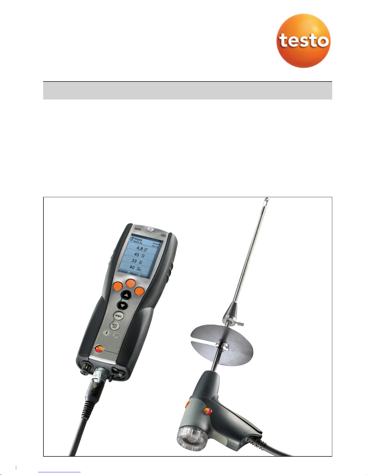
testo 340
Flue gas analyser
1.800.561.8187 info@Testo-Direct.ca
www.Testo-Direct.ca
Page 2
General notes
Please read this documentation through carefully and familiarise yourself with the operation of the product before putting it to use. Keep this document to hand so that you can
refer to it when necessary.
This document describes the country-specifi c version GB of the testo 340 measuring
instrument.
Identifi cation
Symbol Meaning Comments
Warning advice: Warning! Read the warning advice carefully and
Serious physical injury could be caused if the specified take the specified precautionary measures!
precautionary measures are not taken.
Warning advice: Caution! Read the warning advice carefully and
Slight physical injury or damage to equipment could take the specified precautionary measures!
occur if the specified precautionary measures are not
taken.
Important note. Please take particular notice.
Text Text appears on the instrument‘s display Key Press the key.
OK
Function key with the function “OK”. Press function key.
xyz Short form for operating steps. See Short form, p. 3.
2
1.800.561.8187 info@Testo-Direct.ca
www.Testo-Direct.ca
Page 3
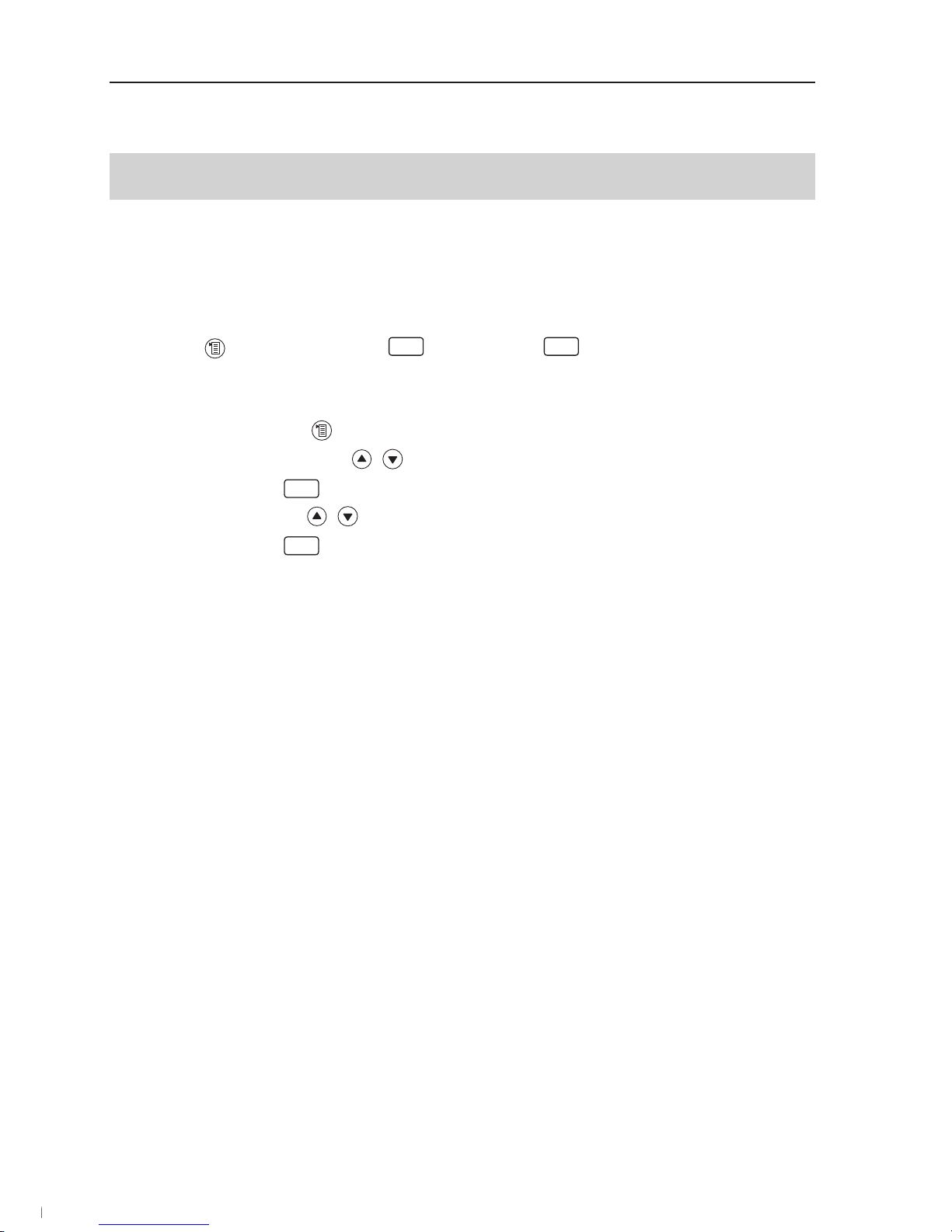
Short form
This document uses a short form for describing steps
(e.g. calling up a function).
Example: Calling up the
Flue gas function
Short form:
Measurements
OK
Flue gas
OK
(1) (2) (3) (4) (5)
Steps required:
1 Open the Main menu:
.
2 Select
Measurements menu: , .
3 Confi rm selection:
OK
.
4 Select
Flue gas menu: , .
5 Confi rm selection:
OK
.
3
1.800.561.8187 info@Testo-Direct.ca
www.Testo-Direct.ca
Page 4

Content
See also Functional overview, p. 60.
General notes ................................................................................................ 2
Content .......................................................................................................... 4
A. Safety advice ......................................................................................... 7
B. Intended purpose .................................................................................. 9
C. Product description ............................................................................ 10
C.1.1 Overview .................................................................................. 10
C.1.2 Keypad ..................................................................................... 11
C.1.3 Display ..................................................................................... 11
C.1.4 Instrument connections ............................................................12
C.1.5 Interfaces ................................................................................. 13
C.1.6 Components ............................................................................ 13
C.1.7 Carrying strap .......................................................................... 14
C.2 Modular fl ue gas probe ................................................................ 14
D. Commissioning .................................................................................... 14
E. Operation ............................................................................................. 15
E.1 Mains unit/rechargeable battery ................................................... 15
E.1.1 Changing the battery ................................................................ 15
E.1.2 Charging batteries .................................................................... 16
E.1.3 Operation with the mains unit ...................................................16
E.2 Probes/sensors ........................................................................... 17
E.2.1 Connecting probes/sensors ..................................................... 17
E.2.2 Replacing the probe module ..................................................... 18
E.3 Regular care ................................................................................ 18
E.3.1 Condensate trap ...................................................................... 18
E.3.2 Checking/replacing the particle fi lter .........................................19
E.4 Basic operating steps .................................................................. 19
E.4.1 Switching the measuring instrument on .................................... 19
E.4.2 Calling up the function ............................................................. 20
E.4.3 Entering values ......................................................................... 20
E.4.4 Printing data ............................................................................. 21
E.4.5 Saving data ..............................................................................21
E.4.6 Confi rming an error message....................................................21
E.4.7 Switching the measuring instrument off ....................................21
4
1.800.561.8187 info@Testo-Direct.ca
www.Testo-Direct.ca
Page 5

E.5 Memory ....................................................................................... 22
E.5.1 Folders ..................................................................................... 22
E.5.2 Location ................................................................................... 23
E.5.3 Protocols .................................................................................. 24
E.5.4 Extras Memory .........................................................................25
E.6 Instrument diagnosis .................................................................... 26
F. Confi guration ....................................................................................... 27
F.1 Instrument settings ...................................................................... 27
F.1.1 Display edit ............................................................................... 27
F.1.2 Printer ...................................................................................... 28
F.1.3 Start keys edit ..........................................................................29
F.1.4 AutoOff ..................................................................................... 29
F.1.5 Communication ........................................................................ 30
F.1.6 Date / Time ..............................................................................30
F.1.7 Language ................................................................................. 30
F.2 Sensor settings ............................................................................ 31
F.3 Fuels ............................................................................................ 35
G. Measuring ............................................................................................ 36
G.1 Preparing measurements ............................................................. 36
G.1.1 Zeroing phases .........................................................................36
G.1.2 Using the modular fl ue gas probe ............................................. 37
G.1.3 Confi guring the reading display ................................................. 37
G.1.4 Set location/fuel ........................................................................37
G.2.1 Flue gas, Flue gas + m/s, Flue gas + Dp2 ................................. 38
G.2.2 Program ................................................................................... 39
G.2.3 Draught .................................................................................... 40
G.2.4 Smoke# /HCT ..........................................................................40
G.2.5 Gas fl ow rate ............................................................................41
G.2.6 Oil fl ow rate .............................................................................. 42
G.2.7 m/s .......................................................................................... 42
G.2.8 Dp2 .......................................................................................... 43
G.2.9 Burner control .......................................................................... 43
H. Transferring data ................................................................................. 45
H.1 Protocol printer ............................................................................ 45
5
1.800.561.8187 info@Testo-Direct.ca
www.Testo-Direct.ca
Page 6

I. Care and maintenance ........................................................................ 46
I.1 Cleaning the measuring instrument .............................................. 46
I.2 Replacing sensors ....................................................................... 46
I.3 Filter for CO, H2-comp., NO exchanging sensors ....................... 47
I.4 Recalibrating sensors................................................................... 47
I.5 Cleaning the modular fl ue gas probe ............................................ 48
I.6 Replacing probe preliminary fi lter ................................................. 48
I.7 Replacing thermocouple .............................................................. 48
J. Questions and answers ...................................................................... 49
K. Technical data ..................................................................................... 50
K.1 Standards and tests .................................................................... 50
K.2 Measuring ranges and accuracies................................................ 50
K.3 Other instrument data .................................................................. 52
K.4 EC declaration of conformity ........................................................ 53
K.5 Principles of calculation................................................................ 53
K.5.1 Fuel parameters ....................................................................... 54
K.5.2 Calculation formulae .................................................................54
K.6 Recommended rinsing times ....................................................... 57
K.7 Cross-sensitivities ........................................................................ 58
L. Accessories/spare parts ..................................................................... 59
Functional overview .................................................................................... 61
6
1.800.561.8187 info@Testo-Direct.ca
www.Testo-Direct.ca
Page 7
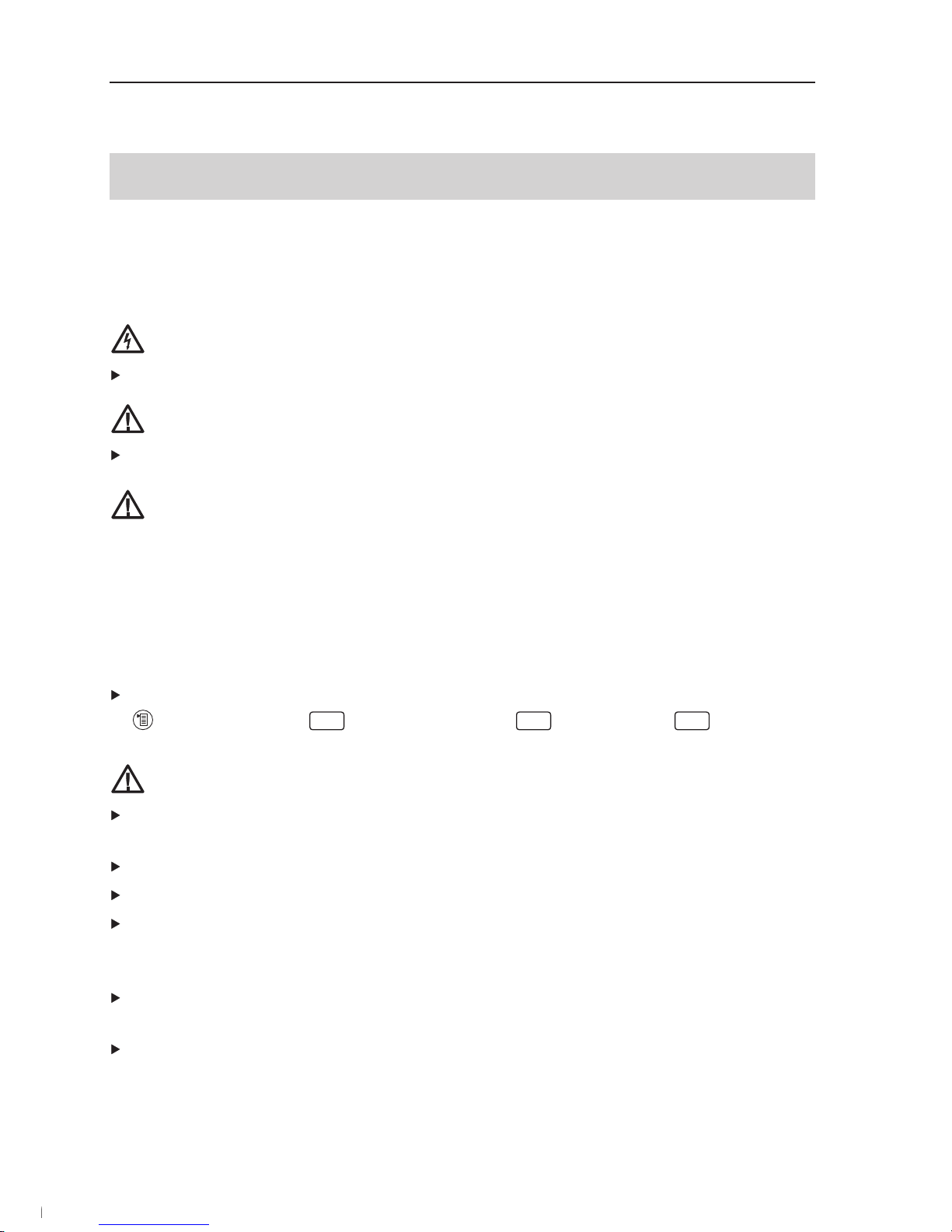
A. Safety advice
Avoid electrical hazards:
Never use the measuring instrument and probes to measure on or near live parts!
Protect the measuring instrument:
Never store the measuring instrument / sensors together with solvents
(e.g. acetone). Do not use any desiccants.
Product with Bluetooth
®
(Option)
Changes or modifi cations, which are not expressly approved by the responsible offi cial
body, can lead to a withdrawal of operating permission.
Interference with data transfer can be caused by instruments which transmit on
the same ISM band, e.g. microwave ovens, ZigBee
The use of radio connections is not allowed in e.g. aeroplanes and hospitals. For this
reason, the following point must be checked before entering:
Deactivate Bluetooth function
Inst’ settings
OK
Communication
OK
Select IrDA
OK
Product safety / preserving warranty claims:
Operate the measuring instrument only within the parameters specifi ed in the Techni-
cal data.
Handle the measuring instrument properly and according to its intended purpose.
Never apply force!
Temperatures given on probes/sensors relate only to the measuring range of the
sensors. Do not expose handles and feed lines to any temperatures in excess of
70 °C unless they are expressly permitted for higher temperatures.
Open the measuring instrument only when this is expressly described in the instructi-
on manual for maintenance purposes.
Carry out only the maintenance and repair work that is described in the instruction
manual. Follow the prescribed steps exactly. For safety reasons, use only original
spare parts from Testo.
7
1.800.561.8187 info@Testo-Direct.ca
www.Testo-Direct.ca
Page 8

Any additional work must only be carried out by authorised personnel. Testo will
other wise refuse to accept responsibility for the proper functioning of the measuring
instrument after repair and for the validity of certifi cations.
Ensure correct disposal:
Dispose of defective rechargeable batteries and spent batteries at the collection
points provided for that purpose.
Send the measuring instrument directly to us at the end of its useful life. We will ensu-
re that it is disposed of in an environmentally friendly manner.
8
1.800.561.8187 info@Testo-Direct.ca
www.Testo-Direct.ca
Page 9

B. Intended purpose
This chapter describes the areas of application for which the measuring instrument is
intended.
The testo 340 is a handheld measuring instrument used in professional fl ue gas analysis
for:
· Engineers servicing/monitoring industrial combustion plants (process systems, power
stations)
· Emissions inspectors
· Engine manufacturers and operators
· Service engineers/mechanics of burner/boiler manufacturers in the industrial sector
Typical measuring tasks and particular characteristics of the testo 340 include:
· Measurement on industrial engines (CO/NO dilution)
· Measurement on gas turbines (high precision CO and NO plus optional dilution)
· Emissions measurement (integrated fl ow speed and differential pressure measurement)
testo 340 should not be used:
· for continuous measurements > 2 h
· as a safety (alarm) instrument
The testo 340 with the Bluetooth option may only be operated in countries in which it
is type approved (see Technical Data).
9
1.800.561.8187 info@Testo-Direct.ca
www.Testo-Direct.ca
Page 10
C. Product description
This chapter provides an overview of the individual components of the product.
C.1 Measuring instrument
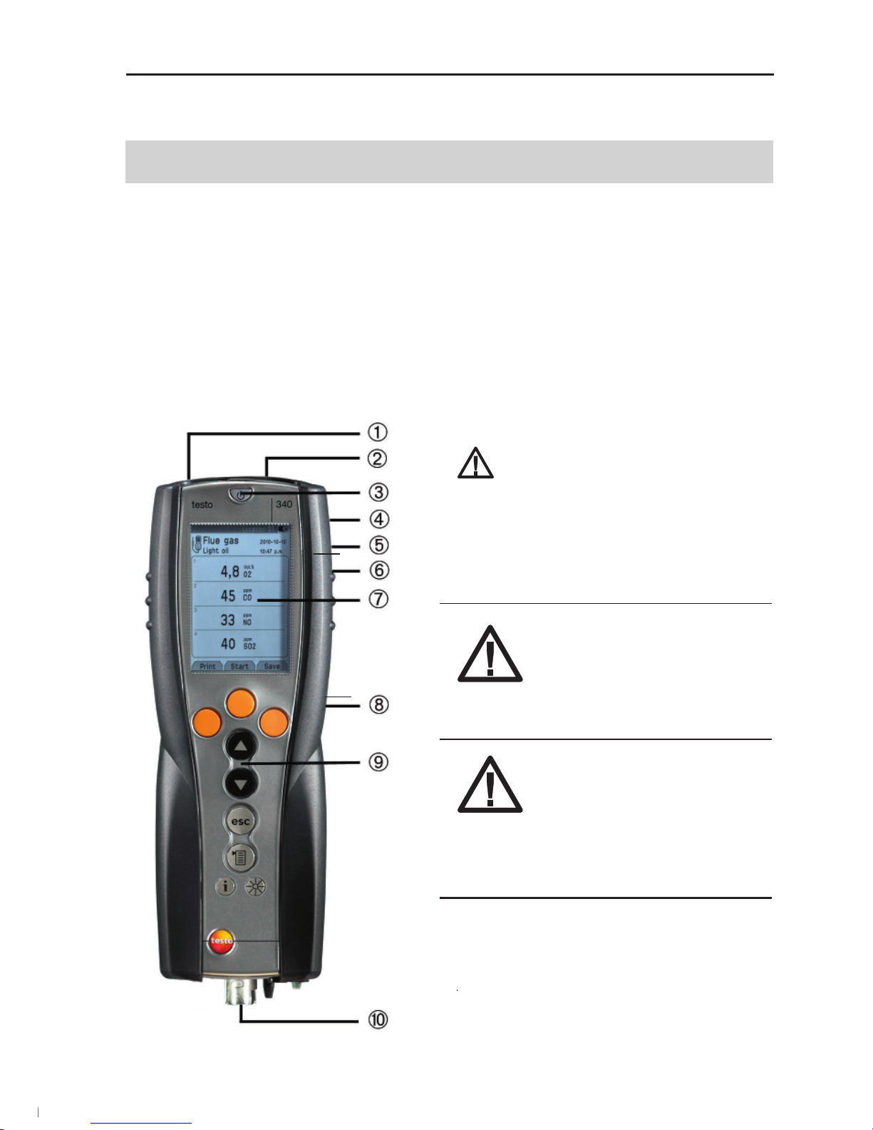
C.1.1 Overview
Infrared interface
Do not point infrared beam at
people‘s eyes!
Interfaces: USB, PS2
On/Off switch
Condensate trap (on rear)
Attachment for carrying strap (on rear)
Magnetic holders (on rear)
WARNING! Magnetic field!
May be harmful to those with pacemakers
> Keep a minimum distance of 20 cm
between pacemaker and instrument.
ATTENTION! Magnetic field!
Damage to other devices!
> Keep a safe distance away from
products which could be damaged by the effects of magnetism
(e.g. monitors, computers or
credit cards)..
Display
Service cover (on rear)
Keypad
Instrument connections: fl ue gas probe,
sensor, pressure probe, mains unit, gas
outlet
10
1.800.561.8187 info@Testo-Direct.ca
www.Testo-Direct.ca
Page 11
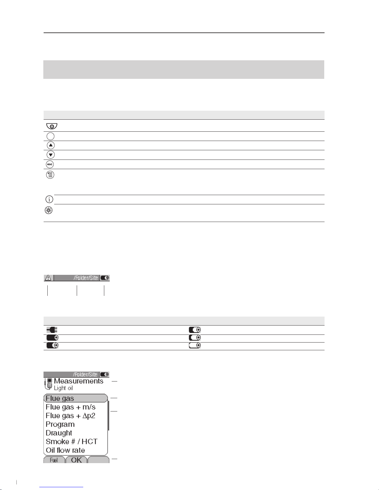
C.1.2 Keypad
Key Functions
Switch measuring instrument on/off
Function key (orange, 3x), relevant function is shown on the display
Scroll up, increase value
Scroll down, reduce value
Back, cancel function
Open Main menu: press briefly (changed settigs are stored, measurement values are carried over into the menu
Flue gas); open Measurements menu: press and hold down for 2s (changed settigs are stored, measurement
values are carried over into the menu Flue gas)
Open Inst’ diagnosis menu
Change display light: display light stays on permanently or display light is switched on for 10s every time the key
is pressed.
C.1.3 Display
Depending on the menu that is active, the display shows a variety of elements.
Header (active in all views)
Warning symbol (only if there is a device error;
device errors are displayed in the
Inst’ diagnosis
menu).
Active folder and location.
Power supply symbol:
Symbol Characteristic Symbol Characteristic
Mains operation Rech. battery operation, capacity: 26-50%
Rech. battery operation, capacity: 76-100% Rech. battery operation, capacity: 6-25%
Rech. battery operation, capacity: 51-75% Rech. battery operation, capacity: 0-5%
Function select view
Active menu, activated fuel
Function selection fi eld:
The selected function has a grey background.
Unavailable functions are written in grey type
Scroll bar
Function keys for entering commands
11
1.800.561.8187 info@Testo-Direct.ca
www.Testo-Direct.ca
Page 12
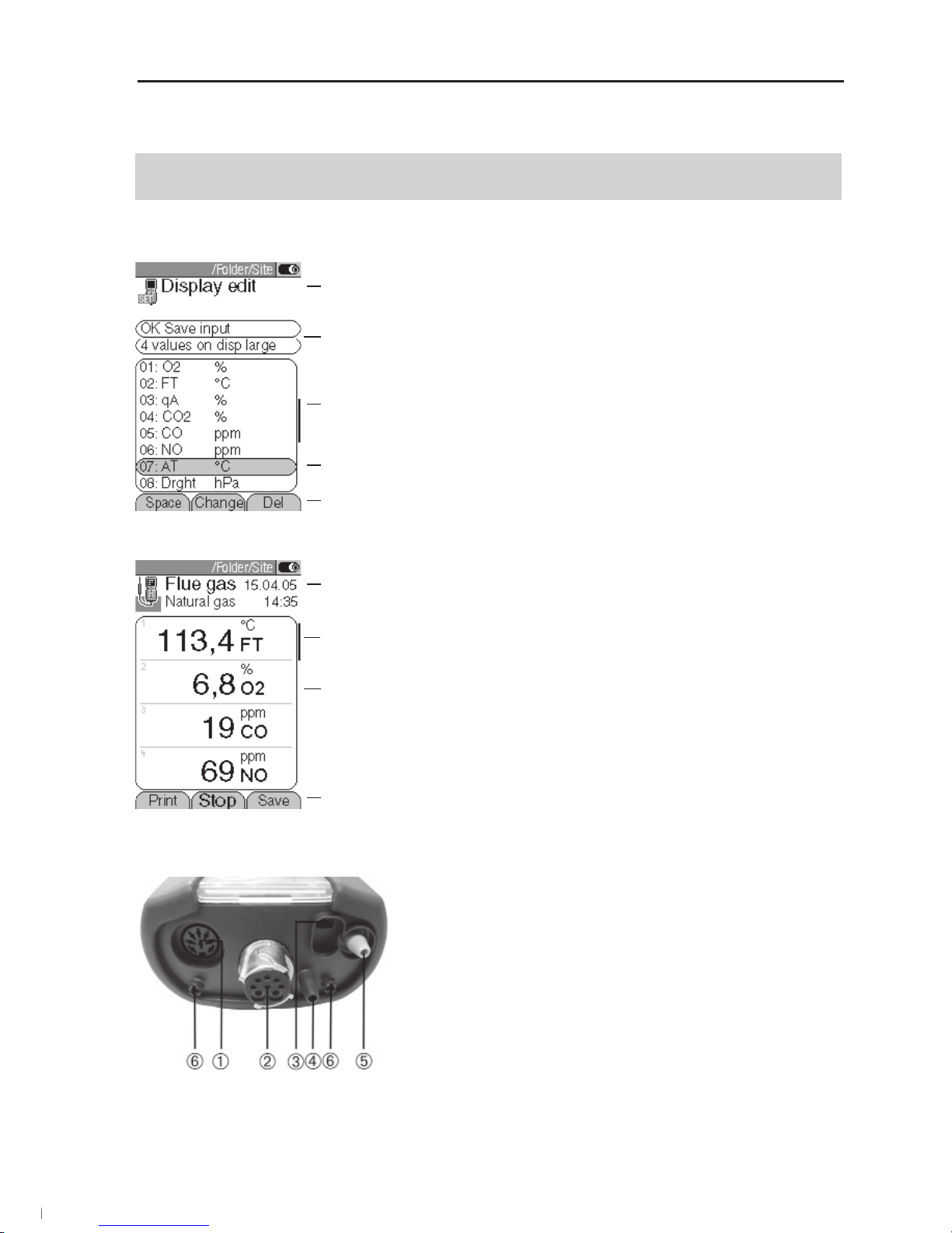
Settings view
Active menu
Function fi elds for entering commands
Scroll bar
Selection fi eld for adjustable values:
The selected value is shown with a grey background. Unavailable values are written in grey type.
Function keys for entering commands
Measuring view
Active menu, depending on the selected function:
Additional information (e.g. activated fuel, date and
time)
Scroll bar
Display fi eld for readings, parameters
Function keys for entering commands
C.1.4 Instrument connections
Sensor socket
Flue gas socket
Mains unit socket
Pressure socket p+
Pressure socket p Gas outlet
12
1.800.561.8187 info@Testo-Direct.ca
www.Testo-Direct.ca
Page 13
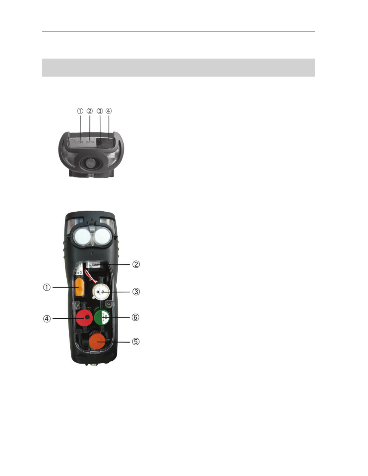
C.1.5 Interfaces
USB interface:
connection to PC
PS2 interface:
Adapter for automatic furnaces
Ir/IrDA interface
Bluetooth interface
C.1.6 Components
Rechargeable battery
Measuring gas pump
Sensor slot 1: O2
Sensor slot 2: CO, COlow, NO, NOlow, SO2
Sensor slot 3: NO, NOlow, NO2
Sensor slot 4: CO, COlow, SO2, NO2
13
1.800.561.8187 info@Testo-Direct.ca
www.Testo-Direct.ca
Page 14
C.1.7 Carrying strap
To secure the carrying strap:
1 Place the measuring instrument on its front.
2 Attach carrying strap in the fi xture (
).
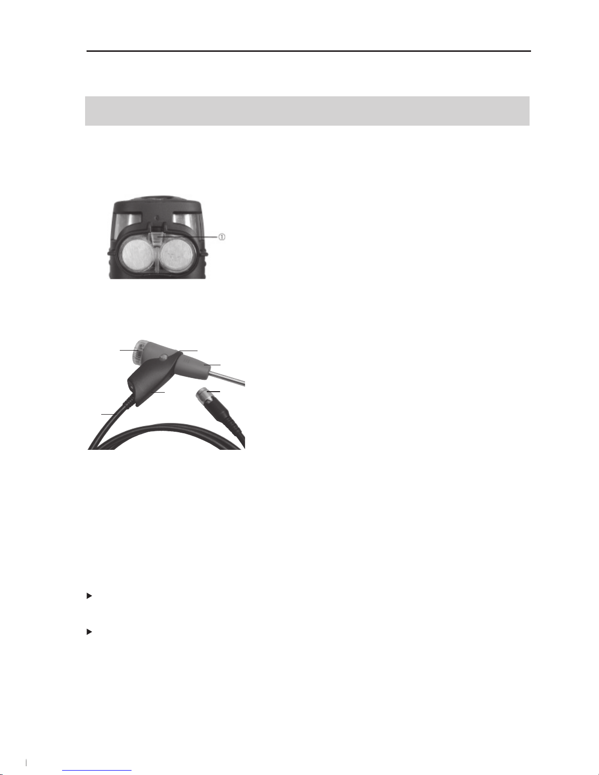
C.2 Modular fl ue gas probe
Removable fi lter chamber with window and particle
fi lter
Probe handle
Connecting lead
Connecting plug for measuring instrument
Probe module release
Probe module
D. Commissioning
This chapter describes the steps required to commission the product.
Remove the protective fi lm from the display.
The measuring instrument is supplied with a rechargeable battery already fi tted.
Charge the rechargeable battery up fully before using the measuring instrument
(see Charging batteries, p. 16).
14
1.800.561.8187 info@Testo-Direct.ca
www.Testo-Direct.ca
Page 15
E. Operation
This chapter describes the steps that have to be executed frequently when using the
product.
Please read this chapter carefully. The following chapters of this document will assume you are already familiar with the content of this chapter.
E.1 Mains unit/rechargeable battery
If the mains unit is connected, the measuring instrument is automatically powered from
the mains unit. It is not possible to charge the rechargeable battery in the measuring
instrument during operation.
E.1.1 Changing the battery
The measuring instrument must not be connected to a mains socket via the mains
unit. The measuring instrument must be switched off. Change the rechargeable battery within 60 minutes, otherwise instrument settings (e.g. date/time) will be lost.
1 Place the measuring instrument on its front.
2 Loosen screws with a Philips screwdriver, release
clip in the direction of the arrow and remove service cover.
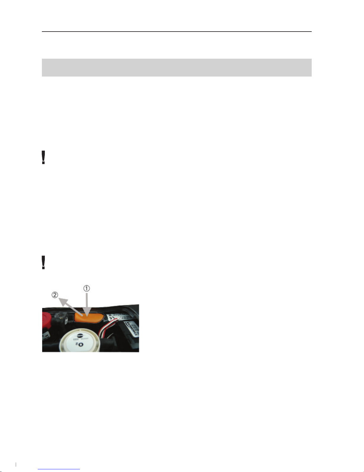
3 Open the rechargeable battery compartment:
Press the orange key (
) and push in the direction
of the arrow (
).
4 Remove the rechargeable battery and insert a new
one. Use only Testo 0515 0100 rechargeable batteries!
5 Close the rechargeable battery compartment:
Press the orange key and push against the direction of the arrow until the rechargeable battery
engages.
6 Replace and close service cover (clip must click
in), fi x with screws.
15
1.800.561.8187 info@Testo-Direct.ca
www.Testo-Direct.ca
Page 16

E.1.2 Charging batteries
The rechargeable battery can only be charged at an ambient temperature of ±0...+35°C.
If the rechargeable battery has discharged completely, the charging time at room temperature is approx. 5-6 hrs.
Charging in the measuring instrument
The measuring instrument must be switched off.
1 Connect the plug of the mains unit to the mains unit socket on the measuring instru-
ment.
2 Connect the mains plug of the mains unit to a mains socket.
- The charging process will start. The charge status will be shown on the display.
The charging process will stop automatically when the rechargeable battery is fully
charged.
Charging in the charger (0554 1103)
Refer to the documentation that comes with the charger.
Battery care
If possible, always discharge the rechargeable battery and recharge it fully.
Do not store the battery for long periods when discharged. (The best storage condi-
tions are at 50-80 % charge level and 10-20 °C ambient temperature; charge fully
before further use).
E.1.3 Operation with the mains unit
1 Connect the plug of the mains unit to the mains unit socket on the measuring instru-
ment.
2 Connect the mains plug of the mains unit to a mains socket.
- The measuring instrument is powered via the mains unit.
- If the measuring instrument is switched off and a rechargeable battery is inserted, the
charging process will start automatically. Switching the measuring instrument on has
the effect of stopping rechargeable battery charging and the measuring instrument is
then power ed via the mains unit.
16
1.800.561.8187 info@Testo-Direct.ca
www.Testo-Direct.ca
Page 17

E.2 Probes/sensors
E.2.1 Connecting probes/sensors
Sensor socket:
Sensor detection is carried out at the sensor socket during the activation process:
Always connect the sensors you need to the measuring instrument before switching
it on or switch the device on and then off again after a change of sensor so that the
correct sensor data are read into the measuring instrument.
Flue gas socket:
Probe/sensor detection at the fl ue gas socket is carried out continuously. It is possib-
le to change the probe/sensor even while the measuring instrument is switched on.
Connecting fl ue gas probes
Plug the connector onto the fl ue gas socket and
lock by turning it clockwise gently (bayonet lock).
There must be no more than two extension leads
(0554 1202) between the measuring instrument
and the fl ue gas probe.
Connecting other sensors
Insert the connector of the sensor into the sensor
socket.
Connecting the pressure tube
Connect the pressure tube/tubes to the connec-
ting nipple/nipples of the pressure socket(s).
17
1.800.561.8187 info@Testo-Direct.ca
www.Testo-Direct.ca
Page 18
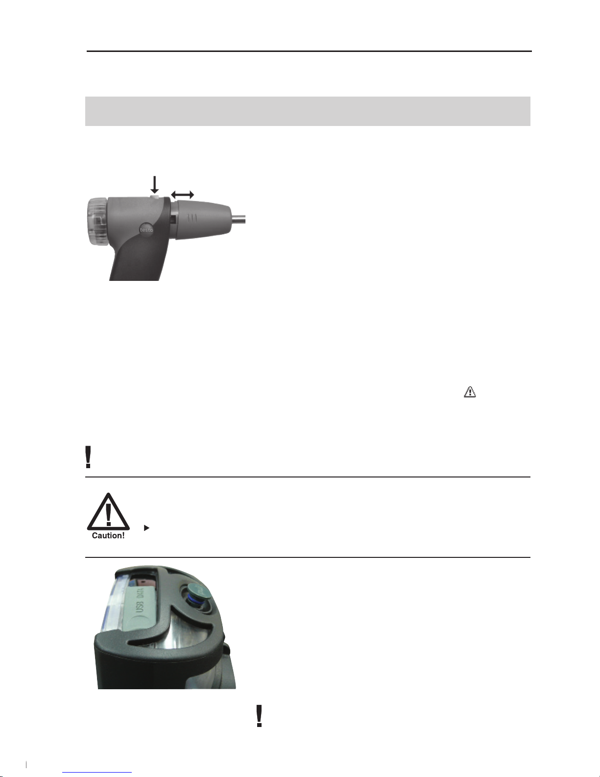
E.2.2 Replacing the probe module
1 Press the key on the top of the probe handle and
remove the probe module.
2 Fit a new probe module and engage it in place.
E.3 Regular care
E.3.1 Condensate trap
The fi ll level of the condensate trap can be read from the markings on the trap. A war-
ning message is displayed if the level in the condensate trap reaches 90% (
, red fl as-
hing light).
Emptying the condensate trap
The condensate consists of a weak mix of acids. Avoid contact with the skin. Make
sure that the condensate does not run over the housing.
Condensate entering the gas path.
Damage to the sensors and fl ue gas pump!
Do not empty the condensate trap while the fl ue gas pump is in operati-
on.
1 Hold the measuring instrument so that the con-
densate outlet points up.
2 Open the condensate outlet of the condensate
trap: Push out plug maximum to the stop).
3 Let the condensate run out into a sink .
4 Mop up any remaining drops on the condensate
outlet using a cloth.
5 Close the condensate outlet.
The condensate outlet must be completely closed
(marking), otherwise measuring errors could occur
if external air gets in.
18
1.800.561.8187 info@Testo-Direct.ca
www.Testo-Direct.ca
Page 19
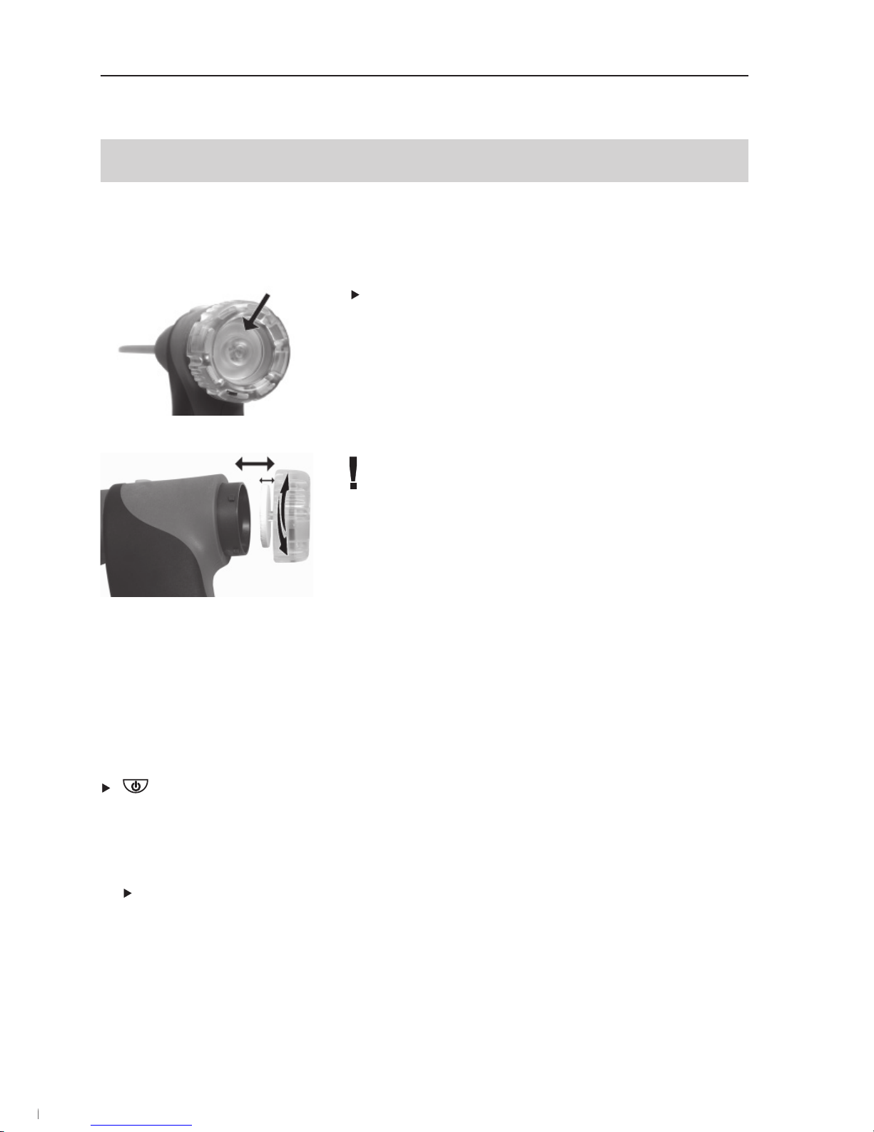
E.3.2 Checking/replacing the particle fi lter
Checking the particle fi lter:
Check the particle fi lter of the modular fl ue gas
probe for contamination at regular intervals: Check
visually by looking through the window of the fi lter
chamber.
Replace the fi lter if there are signs of contamination
Replacing the particle fi lter:
The fi lter chamber may contain condensate
1 Open the fi lter chamber by turning it gently anti-
clockwise.
2 Remove the fi lter plate and replace it with a new
one (0554 3385).
3 Fit the fi lter chamber again and close it by turning it
gently clockwise.
E.4 Basic operating steps
E.4.1 Switching the measuring instrument on
.
- The start screen is displayed (for about 5 s).
- Display light is switched on for 10 s.
Option:
To go directly to a measurement while the start screen is being displayed, press
the function key for the desired measurement. See also Start keys edit, p. 29.
- The
Measurements menu is opened.
-or-
- If the power supply was interrupted for a longer period: the
Date / Time menu is ope-
ned.
-or-
- There is a device error: The
Error diagnosis is displayed.
19
1.800.561.8187 info@Testo-Direct.ca
www.Testo-Direct.ca
Page 20

E.4.2 Calling up the function
Functions which cannot be selected because the required sensor/probe is not
connected are shown in grey type.
1 Select function:
, .
- The selected function is shown with a grey background.
2 Confi rm selection:
OK
.
- The selected function is opened.
E.4.3 Entering values
Some functions require values (numbers, units, characters) to be entered. Depending
on the function that is selected, the values are entered via either a list fi eld or an input
editor.
List fi eld
1 Select the value to be changed (number, unit):
, .
2 Adjust the value:
, .
3 Repeat steps 1 and 2 as required.
4 Confi rm the input:
OK
.
5 Save the input:
OK Save input
OK
.
Input editor
1 Select value (character): , , , .
2 Accept the value:
OK
.
Options:
Switch between uppercase/lowercase letters:
A <=> a (not always available).
Delete character: <=.
To position the cursor in the text: Select the text
input fi eld:
, and position the cursor:
, .
To delete character in front of the cursor:
Del
.
3 Repeat steps 1 and 2 as required.
4 Save the input:
OK Save input
OK
.
20
1.800.561.8187 info@Testo-Direct.ca
www.Testo-Direct.ca
Page 21

E.4.4 Printing data
Data are printed out via the function key
Print
. The function is only available if a printout is possible.
If data are to be transferred to a protocol printer via the infrared or Bluetooth interface,
the printer that is to be used must be activated, see Printer, p. 28.
E.4.5 Saving data
Data are saved either via the function key
Save
or the function fi eld OK Save input. The
functions are only available if saving is
possible.
See also Memory, p. 22.
E.4.6 Confi rming an error message
If an error occurs, an error message is shown in the display.
To confi rm an error message:
OK
.
Errors which have occurred and have not yet been rectifi ed are shown by a warning
symbol in the header (
).
Messages for errors which have not yet been rectifi ed can be viewed in the
Error diagno-
sis
menu, see Instrument diagnosis, p. 26.
E.4.7 Switching the measuring instrument off
Unsaved readings are lost when the measuring instrument is switched off.
.
- Possibly: The pump starts and the senors are rinsed until the shutoff thresholds
(O
2
> 20%, other parameters < 50ppm) are reached. Rinsing lasts no more than 2
minutes.
- The measuring instrument switches off.
21
1.800.561.8187 info@Testo-Direct.ca
www.Testo-Direct.ca
Page 22

E.5 Memory
All readings are allocated to the location that is activated at the time and can be saved
in the Flue gas menus. Unsaved readings are lost when the measuring instrument is
switched off.
Folders and locations can be created (max. 100 folders, max. 10 locations per folder),
edited and activated and measurement protocols can be printed.
The special function
Extras memory can be used to display the remaining free memory
space. All protocols can be printed or deleted. The entire memory (folders and locations
incl. protocols) can also be cleared.
Calling up the function:
Memory
OK
.
E.5.1 Folders
Creating a new folder:
Folders are given a unique identifi cation via the folder number. A folder number can only
be allocated once. The folder number cannot be changed afterwards.
1
New Folder
OK
.
2 Select
Folder Number
change
.
3 Enter values
OK Save input
OK
.
4 Repeat steps 2 and 3 for the other criteria as required.
5
OK
.
Ordering the folders list:
1
Folders list.
2 Select the order criterion:
Folder, Name, Addr’
.
Restoring the folders list:
Order the list in the sequence in which the folders were created:
Restore list
OK
.
Editing folders:
Select the folder.
Options:
Delete the folder:
Del
.
Edit the folder:
Edit
.
22
1.800.561.8187 info@Testo-Direct.ca
www.Testo-Direct.ca
Page 23

E.5.2 Location
Creating a new location:
A location is always created in a folder.
1 Select the folder
OK
New location
OK
.
2 Select the
Location name
Change
.
3 Enter values
OK Save input
OK
.
4 Repeat steps 2 and 3 for the other criteria accordingly.
5
OK Go to measurement or OK To location
OK
.
Ordering the locations list:
1 Select the folder
OK
.
2
Locations list
OK
.
Activating a location:
Select the folder
OK
Select location
OK
.
- The location is activated and the
Measurements menu is opened.
Restoring the locations list:
To arrange the list in the order in which the folders were created:
Select the folder
OK
Restore list
OK
.
Delete a location:
1 Select the folder
OK
.
2 Select the location
Edit
.
3 Select
Delete site with data
OK
.
Performing location settings:
For fl ow speed, air fl ow and mass fl ow to be measured correctly, the shape and surface
area of the cross-section must be set.
The parameters
Pitot factor and Offset factor infl uence the measurement of fl ow speed, air
fl ow and mass fl ow. The Pitot factor is dependent on the Pitot tube used:
· Straight Pitot tubes (0635 2041, 0635 2042): Pitot factor 0.67
· Prandtl (curved) Pitot tubes (0635 2145, 0635 2345): Pitot factor 1.00
The correction factor refers to the stated areas. If part of the area is covered (e.g. by gril-
le bars), this can be compensated via the correction factor. The free portion of the area
should be given (e.g.. 20% covered and 80% free: correction factor 0.8). The correction
factor should be set at 1.00 for all standard applications.
23
1.800.561.8187 info@Testo-Direct.ca
www.Testo-Direct.ca
Page 24

The parameters Temp./amb. (ambient air temperature), Hum/amb. (ambient air humidity)
and
Dew p./amb. (ambient air dew point) infl uence calculation of the qA (Flue gas loss)
and DP (Flue gas dew point temperature). The parameters should be set to the factory
settings for all standard applications (Temp./amb.: 20.0 °C, Hum/amb.: 80.0 %, Dew p./
amb.: 16.4 °C). To achieve greater accuracy, the values can be adjusted to the actual
ambient conditions.
If the ambient air temperature sensor is plugged in, the value for Temp./amb. is accepted automatically. The parameter
Dew p./amb. can be calculated from the values of Temp./
amb.
and Hum/amb. via the function key
calc
.
1 Select the folder
OK
.
2 Select the location
Edit
.
Options:
To set the shape of the cross-section:
Cross section
Change
Select the cross-section
.
To set the surface area of the cross-section:
Cross section
Change
Select the cross-section
Change
Set the values
OK
.
To set parameters:
Select the parameter
Change
Set the values
OK
.
3
OK To location
OK
.
E.5.3 Protocols
Printing/deleting all protocols :
Select the folder
OK
Select a location
Data
.
- The saved protocols are displayed. Protocols of measurement programs are marked
with a vertical line and the number of individual measurements (e.g.
|245), for more
than 999 measurements dots are used (
|...). If automatic furnace data are stored with
a measurement protocol the following symbol is displayed next to the protocol name:
. The data are printed with the protocol printout.
Options:
To print all data: Print all
OK
.
To delete all data: Delete all
OK
.
24
1.800.561.8187 info@Testo-Direct.ca
www.Testo-Direct.ca
Page 25

Displaying/printing/deleting an individual protocol:
1 Select the folder
OK
Select a location
Data
.
- The saved protocols are displayed. Protocols of measurement programs are marked
with a vertical line and the number of individual measurements (e.g.
|245), for more
than 999 measurements dots are used (
|...). If automatic furnace data are stored with
a measurement protocol the following symbol is displayed next to the protocol name:
. The data are printed with the protocol printout.
2 Select the protocol
Value
.
Options:
To print the data:
Print
.
To delete the data:
Del
.
E.5.4 Extras Memory
Calling up the function:
Memory
Extra
.
- The remaining free memory space is displayed.
Options:
Print all data
OK
.
Delete all data
OK
.
Delete memory
OK
.
25
1.800.561.8187 info@Testo-Direct.ca
www.Testo-Direct.ca
Page 26

E.6 Instrument diagnosis
Important operating values and instrument data are displayed. A gas path check can
be carried out. The status of the sensors and any device errors not yet rectifi ed can be
displayed.
Calling up the function:
Inst’ diagnosis.
-or .
Performing a gas path check:
1
Gas path check
OK
.
2 Place the black sealing cap on the tip of the fl ue gas probe.
- The pump fl ow is displayed. If the fl ow rate 0.02 l/min, the gas paths are not lea-
king.
3 End the check:
OK
.
Viewing device errors:
Error diagnosis
OK
.
- Unrectifi ed errors are displayed.
View next/previous error: , .
Viewing the sensor diagnosis:
1
Sensor check
OK
.
- Possibly: Gas zeroing (30 s).
2 Select the sensor:
, .
- The status of the sensor is displayed.
26
1.800.561.8187 info@Testo-Direct.ca
www.Testo-Direct.ca
Page 27

F. Configuration
This chapter describes the possible steps for adapting the product to the particular
measurement task or the requirements of the user.
Familiarity with the contents of the chapter Operation (see p. 15) is assumed.
F.1 Instrument settings
F.1.1 Display edit
The parameters/units and the display representation (number of readings displayed per
display page) can be set.
Available parameters and units (may vary from one instrument to another):
Display Parameter Units
FT Flue gas temperature °C, °F
AT Ambient temperature °C, °F
CO2 Carbon dioxide %
O2 Oxygen
%
CO Carbon monoxide ppm, %, g / GJ,
mg/m3, mg/kW
uCO Carbon monoxide undiluted ppm
NO Nitrogen monoxide ppm, %, g / GJ,
mg/m
3
, mg/kW
NOx Nitrogen oxide ppm, %, g / GJ,
mg/m
3
, mg/kW
AT Ambient temperature °C, °F
Drght Flue draught mbar, hPa, mmWS,
inW, Pa, psi, inHG
SO2 Sulfur dioxide ppm, %, g / GJ,
mg/m3, mg/kW
NO2 Nitrogen dioxide ppm, %, g / GJ,
mg/m
3
, mg/kW
Itemp Instrument temperature °C, °F
DP Flue gas dew point temp. °C, °F
Effn Effency referred to net %
calorific value
Effg Effency referred to gross %
calorific value
ratio Poison index -
ExAir Air ratio %
Display Parameter Units
Air Air ratio %
P2 Differential pressure mbar, hPa, Pa,
(200hPa) mmWS, inW, psi,
inHG
Gasfl Gas flow rate m
3
/h, l / min
GasP Gas burner output kW
OilFl Oil flow rate kg/h
Oil p Oil pressure bar
OilP Oil burner output kW
Pabs Absolute pressure hPa , mbar, Pa,
mmWS, inW, psi,
inHG
Pump Pump output l / min
P1 Differential pressure (40hPa) mbar, hPa, Pa,
mmWS, inW, psi,
inHG
Speed Flow speed m/s, fpm
Flow Airflow m
3
/s, m3/m, m3/h,
m
3
/d, m3/y, f3/s,
f
3
/m, f3/h, f3/d,
f
3
/y, l/min
MCO, Mass flow kg/h, kg/d, t/d, t/y,
MNOx, lb/h
MSO2
H2 Hydrogen ppm
27
1.800.561.8187 info@Testo-Direct.ca
www.Testo-Direct.ca
Page 28

Calling up the function:
Inst’ settings
OK
Display edit
OK
.
Setting the display representation:
Select 4 values on disp large or 8 values on disp small
OK
.
Changing parameters and units:
1 Select the display position.
Options:
To insert a space:
Space
.
To delete a parameter:
Del
.
2
Change
Select parameter
OK
Select unit
OK
.
Saving settings:
OK Save input
OK
.
F.1.2 Printer
The headers (lines 1-3) and the footer for the printout can be set. The printer that is used
can be activated.
Calling up the function:
Inst’ settings
OK
Printer
OK
.
Setting the print text:
1
Print text
OK
.
2 Select
Line 1, Line 2, Line 3 or Footnote
Change
.
3 Enter the values
OK Save input
OK
.
4 Repeat steps 2 and 3 for the other lines in the same way.
5
OK Save input
OK
.
Printer selection:
The printer 0554 0543 can only be selected after activating bluetooth, see Communication, p. 30.
Select Printer
OK
Select Printer
OK
.
28
1.800.561.8187 info@Testo-Direct.ca
www.Testo-Direct.ca
Page 29

F.1.3 Start keys edit
The assignment of the function keys depends on the function that is selected. Only the
function keys in the start screen (shown when the measuring instrument is switched on)
can be assigned any function from the
Measurements menu.
The function keys are only active if the required sensors are connected.
Calling up the function:
Inst’ settings
OK
Start keys edit
OK
.
Assigning functions to the start keys:
1 Select function Press the function key that is to be assigned the selected function.
2 Repeat step 1 for the other function keys as required.
Saving settings:
OK Save input
OK
.
F.1.4 AutoOff
With the AutoOff function active, the instrument switches itself off automatically if no key
is pressed after the set period of time.
Calling up the function:
Inst’ settings
OK
AutoOff
OK
.
Switching AutoOff on and off:
Select Auto Off
Change
select On or Off
OK
.
Setting the AutoOff time:
Select Time
Change
Set the value
OK
.
29
1.800.561.8187 info@Testo-Direct.ca
www.Testo-Direct.ca
Page 30

F.1.5 Communication
Select interface IR/IrDA/ interface Bluetooth.
Calling up the function:
Inst’ settings
OK
Communication
OK
Set interface IR/IrDA / interfaceBluetooth:
Select IrDA oder Bluetooth
OK
F.1.6 Date / Time
The date and the time can be set.
Calling up the function:
Inst’ settings
OK
Date / Time
OK
Setting the date/time:
Select Time or Date
Change
Set the values
OK
.
Saving settings:
OK Save input
OK
.
F.1.7 Language
The menu language can be set.
Calling up the function:
Geräteeinst.
OK
Sprache
OK
.
-or-
Inst’ settings
OK
Language
OK
.
Setting the language:
Select Deutsch or Englisch
OK
.
-or-
Select German or English
OK
.
30
1.800.561.8187 info@Testo-Direct.ca
www.Testo-Direct.ca
Page 31

F.2 Sensor settings
It is possible to set an NO2 addition and thresholds for activating sensor protection
(dilution/disconnect). The actual calibration data and the status of the sensors can be
displayed. Recalibration can be carried out.
Calling up the function:
Sensor settings
OK
.
Setting the NO2 addition (as long as no NO2 sensor is plugged in):
1
NO2 addition.
Option:
Reset N02 addition to default value:
Deflt
.
2
Change
Set the value
OK
.
Schematic presentation of gas path testo 340:
Slot 2
Slot 1
Slot 3
Slot 4
Flue gas
Controlled
measuring gas
pump
Mixing
chamber
Mixing
chamber
3/2 way value
Fresh air pump
Fresh air
Dilution 2x:
All measuring cell slots (option)
Dilution 5x:
measuring cell slot 2
CO, H2-comp.
COlow, H2-comp.
SO2
NO2
NO
NOlow
NO2
O2
CO,H2-comp.
COlow, H2-comp.
NO, NOlow, SO2
Slot 1 Slot 2 Slot 3 Slot 4
O2 CO, H2-comp. NO CO, H2-comp.
COlow, H2-comp. NOlow COlow, H2-comp.
NO NO2 SO2
NOlow NO2
SO2
31
1.800.561.8187 info@Testo-Direct.ca
www.Testo-Direct.ca
Page 32

Setting sensor protection:
To extend the measuring range and protect the sensors against overloads, you can set
thresholds which, when exceeded, activate sensor protection. Thresholds for a variety
of parameters can be set, depending on the sensors that are connected.
For instruments without „Dilution of all sensors“ option: If a threshold of the sensor in
slot 2 is exceeded, the gas to sensor 2 is diluted by a factor of fi ve.
There is switch-off if a sensor threshold value is exceeded in slot 3 or slot 4.
For devices with the „Dilute all sensors“ option: If a sensor threshold value is exceeded in slot 2, the gas to sensor 2 is diluted by factor fi ve. If a sensor threshold value is
exceeded in slot 3 or slot 4, gas to all sensors is diluted by factor two.
With dilution active, the reading resolution and accuracies will change, see Technical
data. Diluted values are represented inversely.
If the threshold is still exceeded despite dilution, the instrument is switched off. To de activate sensor protection, set the thresholds to 0 ppm.
1
Sensor protection
OK
.
2 Select the parameter.
Option:
Reset selected parameter to default value:
Deflt
.
3
Change
Set the values
OK
.
4 Repeat steps 2 and 3 for the other parameters accordingly.
Saving settings: OK Save input
OK
.
Measurement CO (H2-compensated) sensor:
In order to protect the sensor and for a longer sensor life, we recommend that in
measurements with unexpectedly high CO concentrations (more than 1,000ppm),
the CO sensor is installed in slot 2, and that the threshold of the CO sensor protection is set to 1,000ppm. From a CO concnetration of 1,000ppm, dilution with a factor
of 5 is automatically activated.
This setting can also be made if H2 concentrations of more than 1,000ppm are to be
expected.
32
1.800.561.8187 info@Testo-Direct.ca
www.Testo-Direct.ca
Page 33

Display ppm/hour counter (active only when sensors with exchangeable fi lters are
used):
For those sensors which have an exchangeable chemical fi lter for neutralizing cross-ga-
ses, a ppm/hour counter is available.
this applies to:
CO, H2 comp. sensor (fi lter life approx. 170000 ppmh)
NO sensor (fi lter life approx. 120000 ppmh)
1
ppm/hour counter
OK
.
2 Select sensors.
Options:
Switch between the individual sensors: , .
Display of max. fi lter life and current hour counter value
When maximum fi lter life is reached, information is displayed: Filter material spent.
Please exchange filter
.
Reset hour counter of a sensor:
back
.
Displaying actual calibration data/sensor status:
Calibrationdata
OK
.
Options:
To change between the actual calibration data of the individual sensors: , .
To print out the actual calibration data of all sensors:
Print
.
To display the status of the sensor as a graphic:
Graphic
.
- The status of the sensor is checked on every recalibration. Any deviation from
the condition on delivery is indicated as a percentage.
70%-threshhold: “Gas cell reading unstable, replace item recommended.“,
50%-threshhold: “Replacement sensor.“
The last 25 recalibrations are shown.
To return to the display of the actual calibration data:
Value
.
Recalibration:
CO, H2-comp, SO2, NO2, NO sensors and the O2 reference value can be recalibrated.
Measurement gas dilution in slot 2 can be recalibrated.
If obviously unrealistic readings are displayed, the sensors should be checked and recalibrated as required.
33
1.800.561.8187 info@Testo-Direct.ca
www.Testo-Direct.ca
Page 34

Dangerous gases
Danger of poisoning!
Observe safety regulations/accident prevention regulations when handling
test gases.
Use test gases in well ventilated rooms only.
Recalibration with low gas concentrations can lead to deviations in accuracy in the
upper measuring ranges.
Sensor protection is deactivated during recalibration. For this reason, test gas concentration should be lower than the maximum value of the sensors.
Recalibrating the sensor at slot 2 has an effect on the dilution:Always carry out a
recalibration of measurement parameters before a recalibration of dilution.
The following conditions must be met when recalibrating:
· Use absorption-free tube material
· Switch the measuring instrument on at least 20 min before recalibration (warming-up)
· Use clean air for gas zeroing
· Charge the test gas via calibration adapter (0554 1205, recommended) or the tip of
the probe
· Maximum overpressure of the test gas: 30 hPa (recommended: unpressurised via
bypass)
· Charge the test gas for at least 3 min
Recommended test gas concentrations and compositions are given in Testo‘s fi eld
guide to test gases.
1
Recalibration
OK
.
- Possibly:Gas zeroing (30 s).
2 Select the parameter
Change
Enter the test gas concentration (nominal value).
3 Charge the analyzer with test gas.
4 Start calibration:
Start
.
If the parameter of the sensor inserted in slot 2 has been selected:
- You will receive a query as to whether dilution should be initialised.
Start recalibration of parameter:
No
Start
.
Start recalibration of dilution:
Yes
Start
.
5 Accept the nominal value as soon as the actual value is stable:
OK
.
34
1.800.561.8187 info@Testo-Direct.ca
www.Testo-Direct.ca
Page 35

F.3 Fuels
The fuel can be selected. The fuel-specifi c coeffi cients can be set. Ten fuels can be set
for each customer.
Calling up the function:
Fuels
OK
.
Activating fuel:
Select the fuel
OK
.
Setting coeffi cients:
1
Coeff.
.
Option:
To reset all coeffi cients to default values: Default values
OK
.
To change the name of the fuel (only possible with customer-specifi c fuel): Name
Change
Set the values
OK
.
2 Select the coeffi cient
Option:
To reset the chosen coeffi cients to default values:
Deflt
.
3
Change
Set the values
OK
.
4
OK Save input
OK
.
The calculation of the fuel factors is carried out via the testo easyEmission software.
35
1.800.561.8187 info@Testo-Direct.ca
www.Testo-Direct.ca
Page 36

G. Measuring
This chapter describes the measuring tasks that can be carried out with the product.
Familiarity with the contents of the chapter Operation (see p. 15) is assumed.
G.1 Preparing measurements
G.1.1 Zeroing phases
Measuring the ambient air temperature (AT)
If no ambient air temperature sensor is connected, the temperature measured by the
thermocouple of the fl ue gas probe during the zeroing phase is used as the ambient
air temperature. All dependent parameters are calculated by this value. This method
of measuring ambient air temperature is suffi cient for systems dependent on ambient
air. However, the fl ue gas probe must be near the intake duct of the burner during the
zeroing phase!
If an ambient air temperature sensor is connected, the ambient air temperature is
measured continuously via this sensor.
Gas zeroing
The fi rst time a gas measuring function is called up after the instrument has been swit-
ched on, the sensors are zeroed.
The fl ue gas probe may already be in the fl ue gas duct during zeroing if a separate
AT sensor is connected.
Draught/pressure zeroing
The pressure sensors are zeroed when a pressure measuring function is called up.
The pressure sockets of the instrument must be free (i.e. unpressurized, not closed)
during zeroing.
36
1.800.561.8187 info@Testo-Direct.ca
www.Testo-Direct.ca
Page 37

G.1.2 Using the modular fl ue gas probe
Checking the thermocouple
The thermocouple of the fl ue gas probe must not lie
against the probe cage.
Check before use. Bend the thermocouple back if
necessary.
Aligning the fl ue gas probe
The fl ue gas must be able to fl ow freely past the
thermo couple.
Align the probe by turning it as required.
RGS
The tip of the probe must be in the centre of the fl ue
gas fl ow.
Align the fl ue gas probe in the fl ue gas duct so that
the tip is in the centre of the fl ow (area of the
highest fl ue gas temperature).
G.1.3 Confi guring the reading display
Only those parameters and units which are activated in the reading display appear in the
reading display, the saved measurement protocols and the protocol printouts.
Before beginning measurements, confi gure the reading display so that the required
parameters and units are activated, see Display edit, p. 27.
G.1.4 Set location/fuel
Before carrying out measurements, the measurement location and the fuel must be correctly selected see Memory, p. 22 and Fuels, p. 35.
37
1.800.561.8187 info@Testo-Direct.ca
www.Testo-Direct.ca
Page 38

G.2 Measurements
G.2.1 Flue gas, Flue gas + m/s, Flue gas + p2
The fl ue gas menus are the central measurement menus in which - in addition to the
readings measured with this function - the readings of all measurements carried out are
displayed (if this is selected in the
Display edit menu). All readings can also be saved in or
printed out from these menus.
The fl ue gas menus are always available, regardless of which sensors are connected.
Measuring functions of the three fl ue gas menus:
· The
Flue gas function enables fl ue gas to be measured.
· The
Flue gas + m/s function enables fl ue gas to be measured in addition to fl ow speed
(+ air/mass fl ow calculation) by means of a Pitot tube (the connection cable for the
straight Pitot tube thermocouple should not be connected to the instrument probe
socket).·
· The Flue gas + p2 function enables fl ue gas to be measured in addition to differential
pressure measurement.
After measurements with high concentrations and longer measurements, the instrument should be rinsed with fresh air in order to enable the sensors to regenerate, see
Chapter Recommended rinsing times, p. 57.
For fl ow speed measurement. Before beginning measurement, confi gure the location
settings (Pitot tube factor and correction factor), see chapter Location, p. 23.
Do not measure for longer than 5 min, as the drift of the pressure sensor means that
the readings could be outside the tolerance limits.
Calling up the function:
Measurements
OK
Flue gas
OK
.
-or-
Measurements
OK
Flue gas + m/s
OK
.
-or-
Measurements
OK
Flue gas + p2
OK
.
- Possibly: gas zeroing (32 s).
For the functions
Flue gas + m/s and Flue gas + p2:
Depressurise the pressure sensor and carry out pressure zeroing with
V = 0
.
If no fuel has yet been selected:
Select the fuel
OK
.
38
1.800.561.8187 info@Testo-Direct.ca
www.Testo-Direct.ca
Page 39

Measuring:
1 Start measuring:
Start
.
- The readings are displayed.
Option:
Interrupt measurement and rinse sensors:
Air
,
Continue measurement:
Gas
.
2 Stop measuring:
Stop
.
Options:
To print readings:
Print
.
To save readings:
Save
.
- The readings from the fl ue gas measurement, as well as any readings taken over
into the menu
Flue Gas from other measurement functions are stored and/or prin-
ted in a measurement protocol (automatic furnace data are not printed).
G.2.2 Program
Five fl ue gas measuring programs can be set, saved and run.
Calling up the function:
Measurements
OK
Program
OK
.
Changing a measuring program:
1 Select the program
Change
.
2
Meas rate
Change
Enter the values
OK
.
3 Repeat step 2 for the other criteria accordingly.
4
OK Save input
OK
.
Running a measuring program:
1 Select the program
Start
.
2 Select
Start without zeroing (only available if gas zeroing has already been carried out)
or
Start with zeroing and start the program with
OK
.
- If selected: Gas zeroing (32 s).
- Stabilisation phase (60 s).
- The program will run and then stop after the programmed time.
Option:
To print readings:
Print
.
To cancel the program:
Stop
, start again:
Start
.
39
1.800.561.8187 info@Testo-Direct.ca
www.Testo-Direct.ca
Page 40

G.2.3 Draught
The Draught function is only available when a fl ue gas probe is connected.
Do not measure for longer than 5 min, as the drift of the pressure sensor means that
the readings could be outside the tolerance limits.
Calling up the function:
Measurements
OK
Draught
OK
.
Measuring:
1 Start measuring:
Start
.
- Draught zeroing (5 s).
2 Position the fl ue gas probe in the centre of the fl ow (area of the highest fl ue gas
temperature). The display showing the maximum measured fl ue gas temperature (FT)
helps when positioning the probe.
- The reading is displayed.
3 Stop measuring
Stop
.
- The reading is recorded.
Option:
To print the reading:
Print
.
4 To copy the reading to the
Flue gas menu:
OK
.
- The
Measurements menu is opened.
G.2.4 Smoke# /HCT
Calling up the function:
Measurements
OK
Smoke#/HCT
OK
.
Recording smoke tester no. / smoke numbers / oil derivative with the smoke pump
and manual input:
The function is only available if the chosen fuel is an oil.
1
Sm. tester no.
Change
Enter the tester number
OK
.
2
Smoke # 1
Change
Enter the value
OK
.
3 Repeat step 2 for the other smoke # and the oil derivative accordingly.
40
1.800.561.8187 info@Testo-Direct.ca
www.Testo-Direct.ca
Page 41

Recording smoke tester no. / smoke numbers / oil derivative with the smoke tester
testo 308 and wireless transfer:
- t308 must be in Data Mode ( ).
1 Press function key
t308
.
- The values recorded by the smoke tester are transferred.
2 Once all values have been transferred, select function key
OK
.
Entering the heat carrier temperature:
Heat carrier
Change
Enter the value
OK
.
Copying values to the Flue gas menu:
The values are not shown on the instrument‘s display. In the menu Flue Gas, they can
be stored and/or printed in a measurement protocol together with the readings from
a fl ue gas measurement, or transferred to a PC
OK Copy readings
OK
.
- The
Measurements menu is opened.
G.2.5 Gas fl ow rate
The Gas flow rate function is only available if the activated fuel is a gas.
Calling up the function:
Measurements
OK
Gas flow rate
OK
.
Measuring:
1 Enter the measurement period:
Sample time
Change
Enter the value (18, 36, or
180
seconds)
OK
.
2 Start measuring:
Start
. Note the counter status of the gas counter.
- The remaining measurement period is displayed.
- When the measurement period has lapsed, a long beep is emitted. The last 5 s are
indicated by a short beep.
3 Enter the fl ow rate:
Gasflow Enter the value
OK
.
- The calculated gas burner output is displayed.
4 Copy the values to the
Flue gas menu: OK Copy readings
OK
.
- The
Measurements menu is opened.
41
1.800.561.8187 info@Testo-Direct.ca
www.Testo-Direct.ca
Page 42

G.2.6 Oil fl ow rate
The Oil flow rate function is only available if the activated fuel is an oil.
Calling up the function:
Measurements
OK
Oil flow rate
OK
.
Measuring:
1 Enter the fl ow rate:
Flowrate
Change
Enter the value
OK
.
2 Enter the oil pressure:
Oil pressure
Change
Enter the value
OK
.
- The calculated oil burner output is displayed.
3 Copy the values to the
Flue gas menu: OK Copy readings
OK
.
- The
Measurements menu is opened.
G.2.7 m/s
A Pitot tube must be connected, the connection cable for the Pitot tube thermocouple must be connected to the instrument probe socket.
To measure fl ow speed, air fl ow and mass fl ow the parameters of cross-section shape,
cross-section surface area, Pitot factor and offset factor must be set, see Location, p.
23.
Do not measure for longer than 5 min, as the drift of the pressure sensor means that
the readings could be outside the tolerance limits.
Calling up the function:
Measurements
OK
m/s
OK
.
Measuring:
1 Start measuring:
Start
.
- Pressure zeroing (5 s).
2 Position the Pitot tube in the duct. The display showing the measured fl ow speed
(Speed) helps when positioning the probe.
- The reading is displayed.
3 Stop measuring:
Stop
.
- The reading is recorded.
Option:
To print the reading:
Print
.
4 Accept the reading:
OK
.
- The Measurements menu is opened.
42
1.800.561.8187 info@Testo-Direct.ca
www.Testo-Direct.ca
Page 43

G.2.8 p2
Do not measure for longer than 5 min, as the drift of the pressure sensor means that
the readings could be outside the tolerance limits.
When measuring the gas fl ow pressure of gas heaters:
Dangerous mixture of gases
Danger of explosion!
Make sure there are no leaks between the sampling point and the
measuring instrument.
Do not smoke or use naked fl ames during measurement.
Calling up a function:
Measurements
OK
p2
OK
.
Measuring:
1 Start measuring:
Start
.
- Pressure zeroing (5 s).
2 Position the Pitot tube in the duct.
3 Stop measuring
Stop
.
- The reading is recorded.
Option:
To print the reading:
Print
.
4 Accept the reading:
OK
.
- The
Measurements menu is opened.
43
1.800.561.8187 info@Testo-Direct.ca
www.Testo-Direct.ca
Page 44

G.2.9 Burner control
With the help of the readout adapter for automatic furnaces (0554 1206), status data
and malfunction reports can be read out from compatible automatic furnaces, see also
documentation for readout adapter. The range of data which can be read out is dependent on the automatic furnace type.
Calling up the function:
1 Connect readout adapter to the instrument (PS2 interface) and the automatic furnace
(use adapter ring if necessary).
2
Measurements
OK
Burner Control.
Option:
Display type and version of the adapter:
Adapt.
.
3
OK
.
- The data are read from the automatic furnace. An update of the data takes place
every 30s at the latest, this is dependent on the automatic furnace.
Reading out current status data:
The current data are displayed when a connection to the automatic furnace exists. The
following data are displayed with the help of symbols:
Component Status ON Status OFF Component Status ON Status OFF
Air controller Flame Symbol
not displayed
Motor Ignition
Valve1 Oil prewarmer
Valve 2
Printing data:
Print
.
Display identifi cation data:
Info
OK
.
Display failure statistic:
Failure statistic
OK
.
44
1.800.561.8187 info@Testo-Direct.ca
www.Testo-Direct.ca
Page 45

Reading out failure store:
Automatic furnaces are equipped with circular buffer memories, i.e. failure reports are
overwritten when the failure store is full.. The last failure occurring is at position 1 in the
failure list.
Failure
.
Option:
Scroll through failure list: , .
Taking readings over into the menu Flue Gas:
The readings are not presented in the display, in the menu Flue Gas they can be stored with the readings from a fl ue gas measurement, stored in a measurement proto-
col or transferred to a PC.
For taking data over into the menu
Flue Gas the function fi elds Info and Failure statistic
must not be active (grey background).
OK
.
- The Menu
Measurements is opened.
H. Transferring data
H.1 Protocol printer
If data are to be transferred to a Testo protocol printer via the infrared or Bluetooth interface, the printer that is to be used must be activated, see Printer, p. 28.
Data are printed out via the function key
Print
. The function is only available if a prin-
tout is possible.
45
1.800.561.8187 info@Testo-Direct.ca
www.Testo-Direct.ca
Page 46

I. Care and maintenance
This chapter describes the steps and action required in order to keep the product functioning properly.
See also Regular care, p. 18.
I.1 Cleaning the measuring instrument
If the housing of the instrument is dirty, clean it with a damp cloth. Do not use any
aggressive cleaning agents or solvents. Weak household cleaning agents and soap
suds may be used.
I.2 Replacing sensors
A slot bridge (0192 1552) must be inserted in slots which do not have a sensor. Used
sensors must be disposed of as special waste!
The measuring instrument must be switched off and the mains unit disconnected from
the mains supply.
1 Place the measuring instrument on its front.
2 Loosen screws with a screwdriver, release clip in the direction of the arrow, and
remove service cover.
3 Pull tube connections from the faulty sensor/bridge.
4 Remove the faulty sensor/bridge from the slot.
Do not remove auxiliary circuit boards of the new
sensors until immediately before installation. Do not
leave the sensors without a auxiliary circuit boards
for longer than 15 min.
NO/NO
low
sensors:
Remove the auxiliary circuit board.
5 Insert a new sensor/bridge in the slot.
6 Attach tube connections to the sensor/bridge.
7 Replace and close service cover (clip must click
in), fi x with screws.
46
1.800.561.8187 info@Testo-Direct.ca
www.Testo-Direct.ca
Page 47

After replacing an O2 sensor, wait 60 min before using the instrument again.
If retrofi tting a sensor you must activate the relevant measuring parameter and unit,
see Display edit, p. 27.
I.3 Filter for CO, H2-comp., NO exch-
anging sensors
The measuring instrument must be switched off and the mains unit disconnected from
the mains supply.
1 Place measuring instrument on its face.
2 Loosen screws with a screwdriver, release clip in the direction of the arrow, and
remove service cover.
3 Remove hose connections from sensor.
4 Remove sensor from slot.
5 Remove spent fi lter from sensor.
6 Place new fi lter on sensor.
Avoid touching the electronics of the sensor.
Observe the markings on the fi lter and the sensor
7 Insert sensor into slot.
8 Replace hose connections on to sensor.
9 Replace and close service cover (clip must click
in), fi x with screws.
10 Reset ppm hour counter (see Display ppm/hour
counter, p. 33.
I.4 Recalibrating sensors
See Sensor settings, p. 31.
47
1.800.561.8187 info@Testo-Direct.ca
www.Testo-Direct.ca
Page 48

I.5 Cleaning the modular fl ue gas probe
Detach the fl ue gas probe from the measuring inst-
rument before cleaning.
1
Release the probe catch by pressing the key on
the probe handle and remove the probe module.
Probe shafts with preliminary fi lter:
Unscrew the preliminary fi lter.
2 Blow compressed air through the fl ue ducts of the
probe module and probe handle (see illustration).
Do not use a brush!
Probe shafts with preliminary fi lter:
Blow compressed air through the preliminary fi lter. For thorough cleaning, use an
ultrasonic bath or a cleaner for dentures. Screw the preliminary fi lter back on to
the probe shaft after cleaning.
3 Fit a new probe module on the handle and engage it in place.
I.6 Replacing probe preliminary fi lter
The preliminary fi lter in probe modules fi tted with a preliminary fi lter can be replaced.
Unscrew the preliminary fi lter from the probe shaft and screw on a new fi lter.
I.7 Replacing thermocouple
1 Release the probe catch by pressing the key on
the probe handle and remove the probe module.
2 Detach the plug-in head of the thermocouple
from its mounting using a screwdriver and pull the
thermo couple from the probe shaft.
3 Lead a new thermocouple into the probe shaft until
the plug-in head engages.
4 Fit probe module on the handle and engage it in
place.
48
1.800.561.8187 info@Testo-Direct.ca
www.Testo-Direct.ca
Page 49

J. Questions and answers
This chapter gives answers to frequently asked questions.
Question Possible causes Remedy
Measuring instrument keeps AutoOff function is switched on. Switch AutoOff function off
switching itself off or (see AutoOff, p. 29).
instrument will not switch on. Battery spent.
Charge rech. battery or connect mains unit
(see Operation, p. 15).
Measuring instrument will Battery spent.
Charge rech. battery or connect mains unit
not switch on. (see Operation, p. 15).
Display of the battery capacity Battery was often not fully discharged /
Discharge rechargeable battery fully (until
appears faulty charged. instrument switches off by itself) and then
charge fully.
Failure report: Gas output closed.
Ensure that gas output is free
Pump flow rate to high
Message: The shutdown threshold of a
Remove probe from flue.
Gas cell shutdown-thres- sensor has been exceeded
hold has been exceeded
Failure report: · With printer 0554 0543: The wrong interface
Activate correct interface
Printing not possible is activated. (see Communication, p. 30).
· The wrong printer is activated.
Activate correct printer
(see Printer, p. 28).
· Printer is switched off.
Switch printer on.
· Printer is out of wireless range.
Place printer within wireless range.
If we could not answer your question, please contact your dealer or Testo Customer
Service. For contact data, see back of this document or web page www.testo.com/
service-contact
49
1.800.561.8187 info@Testo-Direct.ca
www.Testo-Direct.ca
Page 50

K. Technical data
K.1 Standards and tests
· As declared in the certifi cate of conformity, this product complies with Directive
2004/108/EEC.
· This product is TÜV approved to EN 50379 part 2, exception: SO2 and NO2 parameters are not tested, recalibration is not blocked.
K.2 Measuring ranges and accuracies
Parameter Measuring range Accuracy Resolution t90
1
O2 0...25Vol.% ±0.2Vol.% 0.01Vol.% < 20s
CO, H2-comp. 0...10000ppm ±10ppm or 1ppm < 40s
±10% of reading
1
at 0...200ppm
±20ppm or
±5% of reading
1
at 201...2000ppm
±10% of reading at 2001...10000ppm
COlow, H2-comp. 0...500ppm ±2ppm at 0.0...39.9ppm 0.1ppm < 40s
±5% of reading at 40.0...500ppm
NO2 0...500ppm ±10ppm at 0...199ppm 0.1ppm < 40s
±5% of reading in rest of range
SO2 0...5000ppm ±10ppm at 0...99ppm 1ppm < 40s
±10% of reading in rest of range
NOlow 0...300ppm ±2ppm at 0.0...39.9ppm 0.1ppm < 30s
±5% of reading at 40.0...300.0ppm
NO 0...3000 ppm ± 5ppm at 0...99ppm 1ppm < 30s
± 5% of reading at 100...1999ppm
±10% of reading at 2000...3000ppm
Draught, p1 -40...40hPa + 1.5% v. Mw.
at -40.00...-3.00hPa 0.01hPa + 0.03hPa at -2.99...2.99hPa
+ 1.5% v. Mw. at 3.00...40.00hPa
p2 -200...200hPa ±1.5% of reading at -200.0...-50.0hPa 0.1hPa ± 0.5hPa at -49.9...49.9hPa
±1.5% of reading at 50.0...200.0hPa
1
Response time 90%, recommended minimum measurement duration to guarantee correct readings: 3min
50
1.800.561.8187 info@Testo-Direct.ca
www.Testo-Direct.ca
Page 51

Parameter Measuring range Accuracy Resolution t90
1
P abs 600...1150hPa ±10hPa 1hPa Temperature (NiCrNi) -40...1200°C ± 0.5°C at 0.0...99°C 0.1°C at -40.0...999.9°C depends
± 0.5% of reading in rest of range 0.1°C
at 1000°C...1200°C on probe
Efficiency 0...120% - 0.1% Flue gas loss 0...99,9% - 0,1% Flue gas dewpoint 0...99,9°C - 0.1% CO2 determination 0...CO2 max. ± 0.2 Vol% 0.1 Vol% <40s
(Calculated
from O2)
1 Response time 90%, recommended minimum measurement duration to guarantee correct readings: 3min
For activated single dilution slot 2 (factor 5)
Parameter Measuring range Accuracy Resolution
CO, H2-comp. 700...50000ppm +10% of reading (additional error) 1ppm
COlow, H2-comp. 300...2500ppm +10% of reading (additional error) 0.1ppm
SO2 500...25000ppm +10% of reading (additional error) 1ppm
NO 500...15000ppm +10% of reading (additional error) 1ppm
NOlow 150...1500ppm +10% of reading (additional error) 0.1ppm
With activated dilution of all sensors (optional) (factor 2)
Parameter Measuring range Accuracy Resolution t90
1
O2 0...25Vol.% ±1Vol.% of reading additional error (0...4,99Vol.%) 0.01Vol.% < 20s
±0,5Vol.% of reading additional error(5...25Vol.%)
CO, H2-comp. 700...20000ppm +10% of reading (additional error) 1ppm
COlow, H2-comp. 300...1000ppm +10% of reading (additional error) 0.1ppm
NO2 200...1000ppm +10% of reading (additional error) 0.1ppm
SO2 500...10000ppm +10% of reading (additional error) 1ppm
NOlow 150.. .600ppm +10% of reading (additional error) 0.1ppm
NO 500...6000ppm +10% of reading (additional error) 1ppm
1
Response time 90%, recommended minimum measurement duration to guarantee correct readings: 3min
Filter lifetime
Parameter Lifetime
CO, H2-comp. 170000 ppmh
NO 120000 ppmh
51
1.800.561.8187 info@Testo-Direct.ca
www.Testo-Direct.ca
Page 52

K.3 Other instrument data
Characteristic Values
Operating temperature -5...50 °C
Storage/transport temperature -20...50 °C
Power supply Battery block: 3.7 V / 2.4 Ah
Mains unit: 6.3 V / 2 A
Dimensions (L x W x H) 283 x 103 x 65mm
Weight 960g
Memory max. 100 folders, max. 10 locations per folder
Display Monochrome, 4 grey levels, 160 x 240 pixels
Battery storage temperature: ±0...35 °C
Battery life > 6 h (pump on, display light off, 20 °C ambient temperature)
Battery charge time approx. 5-6 h
Pump perform.against x hPa Max. positive pressure at probe tip: + 50 mbar
Max. negative pressure at probe tip: -200 mbar
Initialization and
zeroing time 30 sec.
Protection class IP 40
Guarantee
Measuring instrument: 24 months
Sensors: 12 months, O2 sensor: 18 months
Flue gas probe: 24 months
Thermocouple: 12 months
Battery: 12 months
Warranty conditions: see www.testo.com/warranty
Option Bluetooth
®
Typ-designation: BlueNiceCom IV
Bluetooth Qualified Product Notice: BNC4_HW2x_SW2xx
Bluetooth listing identifier: BO13784
Bluetooth listing company: 10274
Option Bluetooth
®
Range <10m
Option Bluetooth
®
EU countries
Certification Belgium (BE), Bulgaria (BG), Denmark (DK), Germany (DE), Estonia (EE), Finland (FI), France
(FR), Greece (GR), Ireland (IE), Italy (IT), Latvia (LV), Lithuania (LT), Luxembourg (LU), Malta (MT),
Netherlands (NL), Austria (AT), Poland (PL), Portugal (PT), Romania (RO), Sweden (SE), Slovakia (SK), Slovenia (SI), Spain (ES), Czech Republic (CZ), Hungary (HU), United Kingdom (GB) and
Republic of Cyprus (CY).
EFTA Countries
Iceland, Liechtenstein, Norway and Switzerland
Other countries
Canada, USA, Japan, Ukraine, Australia, Columbia, Turkey, El Salvador
52
1.800.561.8187 info@Testo-Direct.ca
www.Testo-Direct.ca
Page 53

K.4 EC declaration of conformity
53
1.800.561.8187 info@Testo-Direct.ca
www.Testo-Direct.ca
Page 54

K.5 Principles of calculation
K.5.1 Fuel parameters
Fuel CO
2 max
O
2 base
Kgr K
net
K
1
H MH2O Qgr Q
net
Natural Gas 11,90 3,00% 0,35% 0,39 40,00 24,4 0 53,42 48,16
Light Oil 15,50 3,00% 0,48% 0,51 53,00 13 0 45,6 42,8
Heavy Oil 15,80 3,00% 0,51% 0,51 54,00 11,5 0,2 42,9 40,5
Coal 18,40 7,00% 0,62% 0,65 63,00 4 13 26,75 25,5
Anthracit 19,10 7,00% 0,67% 0,69 65,00 3 12 29,65 28,95
Coke 20,60 7,00% 0,75% 0,76 70,00 0,4 10 27,9 27,45
Propane 13,80 3,00% 0,42% 0,45 48,00 18,2 0 50 46,3
Butan 4,10 3,00% 0,43% 0,46 48,00 17,2 0 49,3 45,8
Test gas 0,00 0,00% 0,00% 0,00 0,00 0 0 0 0
Diesel 15,60 3,00% 0,49% 0,53 53,00 12,9 0 44,62 41,8
Petrol 15,10 3,00% 0,46% 0,49 51,00 14,2 0 45,1 42,02
K.5.2 Calculation formulae
Carbon dioxide: CO2 =
CO
2max
x (O
2base
- O2)
O
2base
C0
2max
: Fuel-specifi c
carbon dioxide value
O
2base:
O2 reference value
O
2
: Measured oxygen
content as %
Effi ciency referred to Gross Effi ciency:
Effg = 100 -
(
(
Kgr x (FT - AT)
CO
2
) + (
(MH2O + 9 x H) x (2488 + 2.1 x FT - 4.2 x AT)
Q
gr
x 1000
) + (
K1 x CO
CO
2
+ CO
)
)
Effi ciency referred to Nett Effi ciency:
Effn= 100 -
(
(
K
net
x (FT - AT)
CO
2
) + (
(MH2O + 9 x H) x (210 + 2.1 x FT - 4.2 x AT)
Q
net
x 1000
) + (
K1 x Qgr x CO
Q
net
x (CO2 + CO)
)
)
Kgr/Knet/Qgr/Qnet/K1/MH2O/H:
Fuel-specifi c factors
FT: Flue gas temperature
AT: Ambient temperature
CO: Measured carbon monoxide
value in %
CO
2
: Calculated carbon dioxide
value in %
54
1.800.561.8187 info@Testo-Direct.ca
www.Testo-Direct.ca
Page 55

Poison index: ratio =
CO
CO
2
x 10000
CO: Measured carbon monoxide
value in %
CO
2
: Calculated carbon dioxide
value
Excess Air (ExAir): =
(
21%
21% - O
2
-1 ) x 100 21%: Oxygen level of air
O
2
: Measured oxygen level in %
Nitrogen oxides: No NO2 sensor connected:
NO
: Measured nitrogen
NO
x
= NO + (NO
2Add.
x NO) monoxide value
NO2 sensor connected: NO
2Add.
: Nitrogen dioxide
NO
x
= NO + NO2 addition factor
Carbon monoxide
undiluted: uCO = CO x
CO
: measured carbon
monoxide content
: Calculated air ratio
Flue gas dew point: P =
ln (
ln (
F
H20
x P
Abs
610.78
F
H20
x P
Abs
610.78
) x 234.175
) - 17.08085
F
H20
: Flue gas-specifi c
water vapour content as
vol.%
P
Abs
: Absolute pressure in
mbar/hPa
Flow speed: v =
575 x P x (FT + 273.15)
P
abs
x
P
abs
: Absolute pressure
P: Differential pressure
FT: Flue gas temperature
: Pitot tube factor
Air fl ow: V = v x a
v: Flow speed
a: Cross-section area
55
1.800.561.8187 info@Testo-Direct.ca
www.Testo-Direct.ca
Page 56

Mass fl ow:
Mass fl ow CO: MCO = CO [kg/h] [ppm] x F
Gas
x 1.25 [kg/m3] x Z
Mass fl ow NO
x
: MNOx = NOx [kg/h] [ppm] x F
Gas
x 2.05 [kg/m3] x Z
Mass fl ow SO
2
: MSO2 = SO2 [kg/h] [ppm] x F
Gas
x 2.86 [kg/m3] x Z Fgas: Fuel-specifi c
humidity value
T: Dew point
Z: Calculation term
(see below)
Calculation term Z: Z =
273.15 x Pabs [mbar]
273.15 +T [°C] x 1013
x V [m
3
/s] x 10-6 [1/ppm] x 3600
Conversion from ppm to mg/scm:
The numerical factor used in the formula (e.g. 1.25 for CO) corresponds to the standard density of the respective gas in mg/m³. Please note:
- for SO2, standard density values in the range from 2.86 to 2.93 are stated in literature (difference between ideal and real gas behaviour for SO2)
- for NOx the standard density of NO2 (2.05), is used, as only this compound is stable (NO combines very quickly after its creation with oxygen to form NO2)
Carbon monoxide: CO [mg/scm] =
O
2base
- O
2Bez
O
2base
- O
2
x CO [ppm] x 1.25
Nitrogen oxide: NOx [mg/scm] =
O
2base
- O
2Bez
O
2base
- O
2
x NOx [ppm] x 2.05
Sulfur dioxide: SO2 [mg/scm] =
O
2base
- O
2Bez
O
2base
- O
2
x SO2 [ppm] x 2.86
O
2base
: O2 Reference value
O
2
: Measured oxygen
content as %
O
2Bez
: Fuel-specifi c
oxygen reference index as %
56
1.800.561.8187 info@Testo-Direct.ca
www.Testo-Direct.ca
Page 57

K.6 Recommended rinsing times
Recommended rinsing times in measurements with high concentrations and longer
measurements:
Rinse instrument: Expose probe to fresh air and start fl ue gas analysis
Parameter Concentration [ppm] Measurement duration [min] Recommended rinsing time [min]
CO 50 60 5
100 30 5
200 20 10
500 10 10
1000 10 15
2000 10 20
4000 5 30
8000 5 60
COlow 10 60 5
20 30 5
50 20 10
100 10 10
200 10 15
500 10 20
NO 50 60 5
100 45 5
200 30 5
500 20 10
1000 10 10
2000 10 20
3000 5 30
NOlow 10 60 5
20 45 5
50 30 5
100 20 10
200 10 10
300 10 20
NO2 10 60 5
20 45 5
50 30 5
100 20 10
200 10 10
500 10 20
SO2 50 60 5
100 30 5
200 20 10
500 15 10
1000 10 10
2000 10 20
5000 5 40
57
1.800.561.8187 info@Testo-Direct.ca
www.Testo-Direct.ca
Page 58

K.7 Cross-sensitivities
Target gas Cross-gas
CO NO SO2 NO2
O2 0 0 01 0
CO(H2) -- 0
2
0
2
0
2
CO(H2low) -- 02 0
2
0
2
NO 0 -- 02(w)
3
6 %
4
NOlow 0 -- 02 <5 %
4
NO2 0 0 <-2 % --
SO2 <5 %
4
0
0-- -110 %
4
SOlow
<5 %
4
0
0-- -110 %
4
Target gas Cross-gas
H2 Cl2 HCl HCN CO2
O2 0 0 0
1
1
0 see
5
CO(H2) 06 0 0 0 0
CO(H2low) 0
6
0 0 0 0
NO 0 0 0 0 0
1
No infl uence up to a few 1000ppm; for cross-concentrations in the %-range 0.3%
2
With non-saturated fi lter.
3
w = changeable fi lter
4
Is compensated, if the cross-gas in the instrument is also measured (i.e. if the instru-
ment is equipped with the corresponding sensors).
5
0.3% O2 per 1% CO2; is compensated
6
after H2-compensation
58
1.800.561.8187 info@Testo-Direct.ca
www.Testo-Direct.ca
Page 59

L. Accessories/spare parts
Designation Article no.
Modular flue gas probes
Modular flue gas probe 335mm, 500°C, thermocouple 0.8mm 0600 9766
Modular flue gas probe 700mm, 500°C, thermocouple 0.8mm 0600 9767
Modular flue gas probe 335mm, 1000°C, thermocouple 0.8mm 0600 8764
Modular flue gas probe 700mm, 1000°C, thermocouple 0.8mm 0600 8765
Modular flue gas probe with preliminary filter 335mm, 1000°C, thermocouple 0.8mm 0600 8766
Modular flue gas probe with preliminary filter 700mm, 1000°C, thermocouple 0.8mm 0600 8767
Probe modules/accessories for modular flue gas probes
Module probe shaft 700mm, 500°C, thermocouple 0.8mm 0554 9767
Module probe shaft 335mm, 1000°C, thermocouple 0.8mm 0554 8764
Module probe shaft 700mm, 1000°C, thermocouple 0.8mm 0554 8765
Module probe shaft with preliminary filter 335mm, 1000°C, thermocouple 0.8mm 0554 8766
Module probe shaft with preliminary filter 700mm, 1000°C, thermocouple 0.8mm 0554 8767
Extension lead for modular flue gas probe, 2.80m 0554 1202
Particle filter, 10 pcs 0554 3385
Replacement preliminary filter for modular flue gas probe with preliminary filter (2 pcs.) 0554 3372
Industry engine probe
Engine probe without pre-filter 0600 7560
Engine probe with pre-filter 0600 7561
Thermocouple with 2.4 m hose, Tmax. 1000 °C 0600 8894
Spare probe shaft for engine probe with pre-filter 0554 7455
Other probes/sensors
Pitot tube, 350mm 0635 2041
Pitot tube, 700mm 0635 2042
Ambient air temperature (AT) sensor, 60 mm 0600 9797
Retrofit sensors
NOlow retrofitting kit 0554 2152
NO retrofitting kit 0554 2150
COlow- , H2-comp.- retrofitting kit 0554 2102
CO-, H2-comp.-retrofitting kit 0554 2100
NO2 retrofitting kit 0554 2200
SO2 retrofitting kit 0554 2250
Replacement sensors
O
2
sensor 0393 0000
CO-, H2-comp. sensor 0393 0100
NOlow sensor 0393 0152
NO sensor 0393 0150
NO2 sensor 0393 0200
SO2 sensor 0393 0250
COlow-, H2-comp. sensor 0393 0102
59
1.800.561.8187 info@Testo-Direct.ca
www.Testo-Direct.ca
Page 60

Designation Article no.
Spare filters
CO-, H2-comp. sensor 0554 4100
NO sensor 0554 4150
Other retrofiting kits
Bluetooth only retrofittable by Testo service
Dilution of all sensors only retrofittable by Testo service
Other accessories
Infrared printer 0554 0549
Bluetooth printer incl. rechargeable battery and charging adapter 0554 0553
Mains unit 0554 1096
Charger with replacement battery 0554 1087
Replacement battery 0515 0100
Replacement thermal paper for printer (6 rolls) 0554.0568
Instrument/PC connecting cable 0449 0047
testo EasyEmission PC configuration software 0554 3334
Transport case 0516 3400
60
1.800.561.8187 info@Testo-Direct.ca
www.Testo-Direct.ca
Page 61

Functional overview
The table gives an overview of the most important functions confi gured on the individual
instruments. Detailed information about the individual functions can be found on the
pages indicated.
Task Call/function see page
Measurements
OK
Flue gas measurement Flue gas
OK
38
Flue gas measurement with parallel flow measurement Flue gas + m/s
OK
(+ air/mass flow calculation) 38
Flue gas measurement with parallel differential Flue gas + p2
OK
pressure measurement 38
Change/save/run measuring program Program
OK
39
Draught measurement Draught
OK
40
Enter smoke #/heat carrier temperature Smoke # / HCT
OK
40
Determine gas flow rate Gas flow rate
OK
41
Determine oil flow rate Oil flow rate
OK
42
Flow speed and pressure measurement m/s
OK
42
Pressure measurement p2
OK
43
Read automatic furnace Burner control
OK
43
Memory
OK
Create new folder New folder
OK
22
Sort folder list by Folder, Name or Addr’ Folders list
Folder
or
Name
or
Addr’
22
Sort locations list by order of creation Restore list
OK
22
Create new location Folder
OK
New location
OK
22
Sort locations list by location name Folder
OK
Locations list
Locat
22
Sort locations list by order of creation Folder
OK
Restore list
OK
22
Activate location Folder
OK
Select location
OK
22
Perform location settings Folder
OK
Select location
Change
22
Display measurement data of one location Folder
OK
Select location
Data
22
Print all measurement data of a location Folder
OK
Select location
Data
Print all
OK
22
Delete all measurement data of a location Folder
OK
Select location
Data
Delete all
OK
22
Display readings of a selected measurement protocol Folder
OK
Select location
Data
Select protocol
Value
22
Print a single measurement protocol Folder
OK
Select location
Data
Select protocol
Print
22
61
1.800.561.8187 info@Testo-Direct.ca
www.Testo-Direct.ca
Page 62

Task Call/function see page
Memory
Extra
Print all protocols in the memory Print all data
OK
22
Delete all protocols in the memory Delete all data
OK
22
Clear whole memory (protocols and locations) Delete memory
OK
22
Inst’ settings
OK
Set reading display Display edit
OK
27
Select printer, set print text Printer
OK
27
Set function key assignment, start screen Start keys edit
OK
27
Set date/time Date / Time
OK
27
Set language Language
OK
27
Set automatic instrument disconnect AutoOff
OK
27
Sensor settings
OK
Display calibration data Calibration data
OK
31
Set NO2 addition NO2 addition
Change
31
Set O2 reference O2 reference
Change
31
Set sensor protection Sensor protection
OK
31
Display ppm/hour counter ppm/hour counter
OK
31
Perform recalibration Recalibration
OK
31
Fuels
OK
Activate fuel Select fuel
OK
35
Change fuel coefficients Select fuel
Coeff.
35
-or - Inst’ diagnosis
OK
Perform gas path check Gas path check
OK
26
View instrument errors Error diagnosis
OK
26
View sensor diagnosis Sensor diagnosis
OK
26
62
1.800.561.8187 info@Testo-Direct.ca
www.Testo-Direct.ca
 Loading...