

t
esto 330i · Flue gas measuring instrument
I
nstruction manual
www.testo-international.com/330imanuals

2

1 Contents
1 Contents
1 Contents ................................................................................................... 3
2 Safety and the environment .................................................................... 5
3 Use ............................................................................................................ 5
4 Product description ................................................................................. 6
4.1. Measuring instrument ...................................................................... 6
4.1.1. Overview ............................................................................................................. 6
4.1.2. Terminal panel left/right ...................................................................................... 8
4.2. Modular flue gas probe .................................................................... 8
5 First steps ................................................................................................ 9
5.1. Commissioning ................................................................................ 9
5.2. Getting to know the product ............................................................. 9
5.2.1. Connecting probes .............................................................................................. 9
5.2.2. Mains unit/rechargeable battery ......................................................................... 9
5.2.2.1. Charging the rechargeable battery ....................................................10
5.2.2.2. Mains operation ..................................................................................10
5.2.3. Switching on and connecting with a mobile terminal device ............................11
5.2.4. Switching off ......................................................................................................11
5.2.5. Using the App ....................................................................................................11
6 Using the product .................................................................................. 12
6.1. Performing settings ........................................................................ 12
6.1.1. Configuring measurements .......................................................................12
6.1.2. Graphics ............................................................................................................13
6.1.3. | Instrument settings | Country version .....................................................14
6.1.4. | Instrument settings | Language ..............................................................14
6.1.5. (Fuels) ........................................................................................................14
6.1.6. | Instrument settings | Sensor protection ..................................................14
6.1.7. | Instrument settings | O2 reference ..........................................................14
6.1.8. | Instrument settings | O2 addition ............................................................14
6.1.9. | Instrument settings | Height compensation ............................................14
6.2. Measuring ...................................................................................... 15
6.2.1. Preparing for measurement ..............................................................................15
6.2.1.1. Checking the condensate container fill level ......................................15
6.2.1.2. Checking the particle filter ..................................................................15
6.2.1.3. Zeroing phases ...................................................................................15
6.2.1.4. Performing a gas path check .............................................................16
6.2.1.5. Installing the probe mount testofix®...................................................16
6.2.1.6. Using the modular flue gas probe ......................................................18
6.2.2. | Flue gas ....................................................................................................19
3

1 Contents
6.2.3. | Draught ..................................................................................................... 19
6.2.4. | COundiluted ............................................................................................. 20
6.2.5. | Smoke number ......................................................................................... 20
6.2.6. | Differential pressure ................................................................................. 20
6.2.7. | Differential temp. ...................................................................................... 21
6.2.8. | O2 supply air ............................................................................................. 21
6.3. Printing readings ........................................................................... 21
6.4. Report ........................................................................................... 21
6.4.1. Add to protocol (save measurement) ............................................................... 22
6.4.2. Finish protocol .................................................................................................. 22
7 Maintaining the product ....................................................................... 23
7.1. Checking instrument status ........................................................... 23
7.1.1. | Instrument settings | Sensor diagnosis .................................................. 23
7.1.2. | Error list .................................................................................................. 24
7.2. Cleaning the measuring instrument .............................................. 24
7.3. Draining the condensate container ............................................... 24
7.4. Opening the measuring instrument ............................................... 25
7.5. Replacing the rechargeable battery .............................................. 28
7.6. Replacing sensors ........................................................................ 28
7.7. Cleaning the modular flue gas probe ............................................ 29
7.8. Replacing the probe module ......................................................... 30
7.9. Checking/replacing the particle filter ............................................. 31
7.10. Changing the thermocouple .......................................................... 31
7.11. Updating the instrument software ................................................. 32
8 Technical data ....................................................................................... 32
8.1.1. Examinations and licenses ............................................................................... 32
8.1.2. Bluetooth® module ............................................................................................ 33
8.1.3. Measuring ranges and resolution ..................................................................... 33
8.1.4. Accuracy and response time ............................................................................ 34
8.1.5. Other instrument data ....................................................................................... 35
8.1.6. Declaration of conformity .................................................................................. 37
9 Tips and assistance .............................................................................. 38
9.1. Questions and answers ................................................................ 38
9.2. Accessories and spare parts ......................................................... 39
4

2 Safety and the environment
Please note the information in the document Commissioning and
Safety (printed version supplied with the product). Make sure that
3 Use
all product users read and observe the safety information!
The testo 330i is a flue gas measuring instrument which in
combination with a separate Android or iOS mobile device and the
testo 330i App enables professional flue gas analysis of
combustion systems:
• Small combustion systems (oil, gas, wood, coal)
• Low-temperature and condensing boilers
• Gas water heaters
These systems can be adjusted using the instrument and checked
for compliance with the applicable limit values.
The instrument has been verified as a short-term measuring
instrument and should not be used as a safety (alarm) instrument.
The following tasks can also be carried out using the instrument:
• Regulating the O
, CO and CO2, NO, NOx values in furnaces for
2
the purpose of ensuring optimal operation.
• Draught measurement.
• Measuring and regulating the gas flow pressure in gas water
heaters.
• Measuring and optimising the flow and return temperatures of
heating systems.
• Ambient measurement - CO and CO
• Detection of CH
(methane) and C3H8 (propane).
4
.
2
• The instrument can be used for measurements on combined
heat and power stations (CHP) in accordance with the
first German Federal Immission Control Ordinance (BImSchV).
• In principal, the CO sensor can also be used for
measurements on CHP stations. If you should carry out
more than 50 measurements on CHP stations per year,
please contact your nearest Testo service centre or send
the testo 330i to testo Service for inspection.
A worn NO
filter of the CO sensor can be ordered as a
x
spare part (item no. 0554 4150) and replaced.
3 Use
5
4 Product description
The use of the wireless module is subject to the regulations
export, import etc. in particular in countries without wireless
Testo guarantees the functionality of its products when
used in accordance with their intended purpose. This
guarantee does not apply to features of Testo products in
combination with unauthorised third-party products.
Competitor products are not authorised by Testo.
As is common practice, Testo generally excludes support,
warranty or guarantee claims relating to functionality that
has not been guaranteed by Testo as part of the product
offered. Claims shall also be excluded in the event of
improper use or handling of the products, e.g. in
combination with unauthorised third-party products.
and stipulations of the respective country of use, and the
module may only be used in countries for which a country
certification has been granted. The user and every owner
has the obligation to adhere to these regulations and
prerequisites for use, and acknowledges that the re-sale,
4 Product description
permits, is his responsibility.
4.1. Measuring instrument
4.1.1. Overview
6
4 Product description
WARNING
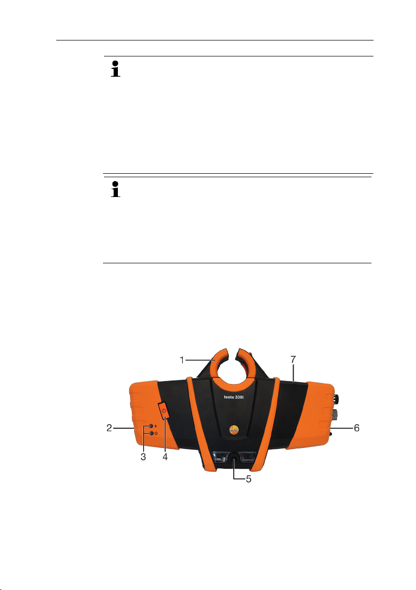
1 Retaining bracket: for attaching to the probe mount testofix
2 Terminal panel left
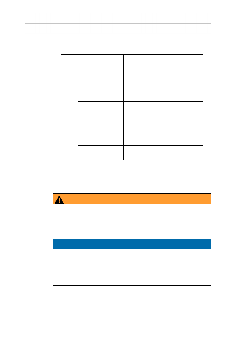
3 Status LEDs:
LED Display Meaning
Blue Off Instrument off or not ready
Flashes (0.05 s
Instrument on, start up phase
on/0.5 s off)
Flashes (0.5 s
on/0.5 s off)
Instrument on, Bluetooth® Find
Device activated
Light is constant Instrument on, Bluetooth®
connection activated
Red Flashes (0.05 s
Device error
on/0.5 s off)
Flashes (0.5 s
on/0.5 s off)
Mains unit plugged in, battery
charging
Light is constant Mains unit plugged in, battery
fully charged
4 ON/OFF button
5 Condensate container, condensate outlet plug
6 Terminal panel right
7. Magnetic holder (on rear)
®
Magnetic field
May be harmful to those with pacemakers.
> Keep a minimum distance of 15 cm between pacemaker and
instrument.
ATTENTION
Magnetic field
Damage to other devices!
> Keep a safe distance away from products that could be
damaged by the effects of magnetism (e.g. monitors,
7
computers or credit cards).
4 Product description
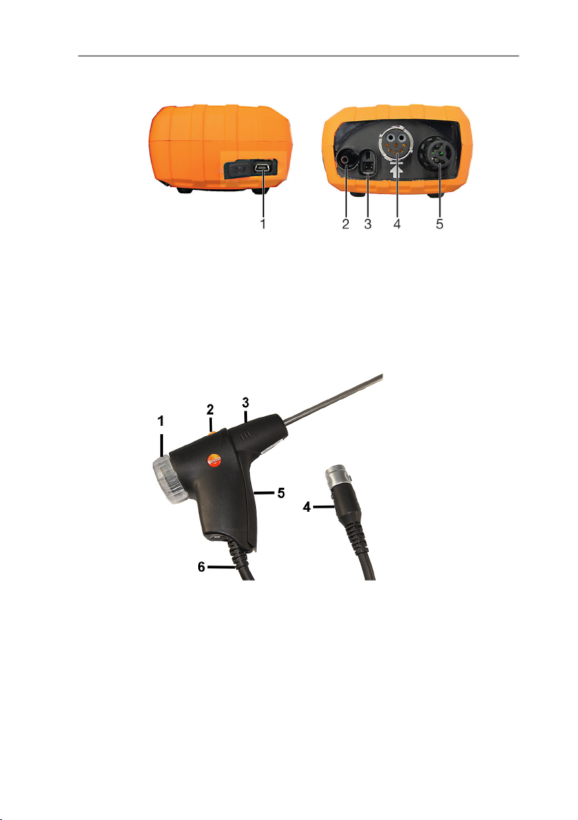
4.1.2. Terminal panel left/right
1 USB interface
2 Minus connection for differential pressure measurement
3 Mains unit socket
4 Flue gas socket
5 Probe socket
4.2. Modular flue gas probe
1 Removable filter chamber with window and particle filter
2 Probe module lock release
3 Probe module
4 Connector plug for measuring instrument
5 Probe handle
6 Connecting cable
8

5 First steps
5.1. Commissioning
Please note the information in the document Commissioning and
5.2. Getting to know the product
5.2.1. Connecting probes
Safety (printed version supplied with the product).
Always connect the probes to the flue gas socket or probe
socket before switching on the measuring instrument;
switch the measuring instrument off and restart after
replacing a probe.
Connecting flue gas probes/gas pressure
adapters/temperature adapters
> Insert the connector plug into the flue gas socket and lock by
slightly turning it clockwise (bayonet lock).
There must be no more than one extension lead (0554
1201) between measuring instrument and flue gas probe.
5 First steps
Connecting other probes
> Insert the connector plug of the probe into the probe socket.
5.2.2. Mains unit/rechargeable battery
If the mains unit is connected, the measuring instrument is
9
automatically powered from the unit.

5 First steps
5.2.2.1. Charging the rechargeable battery
The rechargeable battery can only be charged at an ambient
temperature of 0 to 35 °C. If the rechargeable battery pack has
discharged completely, the charging time at room temperature is
approx. 5-6 hrs.
1. Connect the instrument plug of the mains unit to the mains unit
socket on the measuring instrument.
2. Plug the mains plug of the mains unit into a mains socket.
- The charging process starts (red LED flashes: 0.5 s on/0.5 s
off).
- The charging process stops automatically when the battery is
charged (red LED is constant).
Rechargeable battery care
• Do not fully exhaust rechargeable batteries.
• Store rechargeable batteries only if charged and at low
temperatures, but not below 0 °C. The best storage conditions
are with a charge level of 30-70% and an ambient temperature
of 0-15 °C. Fully charge before using again.
• Optimal charging temperature at 20 °C ambient temperature.
• Trickle charging should not exceed 2 days.
5.2.2.2. Mains operation
1. Connect the instrument plug of the mains unit to the mains unit
socket on the measuring instrument.
2. Plug the mains plug of the mains unit into a mains socket.
- The measuring instrument is powered via the mains unit.
- If the measuring instrument is switched off and a rechargeable
battery is inserted, the charging process will start automatically.
Switching the measuring instrument on has the effect of
stopping the battery charging and the measuring instrument is
then powered via the mains unit.
10

5 First steps
5.2.3. Switching on and connecting with a mobile terminal device
✓ The testo 330i App must be installed on your mobile terminal
device. Please note the information in the document
Commissioning and Safety (printed version supplied with the
product).
1. Switch on the measuring instrument: Press the key.
- Measuring instrument starts up: The blue LED flashes (0.05 s
on/0.5 s off).
- Connecting mode is activated: The blue LED flashes (0.5 s
on/0.5 s off).
2. Switch on the mobile terminal device.
3. Start up the testo 330i App on your mobile terminal device.
- The Find Device function is activated: Compatible devices
within wireless range are displayed (product designation +
serial number).
> Tap instrument designation to select an instrument.
- A Bluetooth
constant.
5.2.4. Switching off
- Measurement type Flue Gas screen is displayed.
Measuring values that have not been saved are lost when
the measuring instrument is switched off.
> Switch off the measuring instrument: Press the key.
- This may happen: the pump starts and the sensors are rinsed
until the switch-off thresholds (O
parameters < 50 ppm) are reached. The maximum rinsing
period is 3 minutes.
- The measuring instrument switches off.
®
connection is established: The blue LED is
> 20%, other measurement
2
5.2.5. Using the App
Make sure you are familiar with how your mobile terminal device
works before using the App; observe the documentation for your
mobile terminal device.
Actions are mainly carried out by touching an icon, a symbol, or a
name.
Some actions require a different gesture. This is pointed out in
each case in this documentation.
11
6 Using the product
AT
O2
1 : Open the Measurement Types selection list
2 : Open/close the Menu selection list
3 : Open the Fuels selection list
4 Select reading display type
5 : Open the Options selection list
6 Start/stop measurement
7 : Open the Protocols selection list
Please also take note of the tutorial in the App under | Help |
6 Using the product
6.1. Performing settings
Tutorial.
6.1.1. Configuring measurements
The measurement parameters/units and the number and order of
displayed measurement parameters in the reading display type can
be set in the List.
Only those parameters and units that are enabled in the reading
display appear in the measured value display, in the saved
measurement records and on the record printouts.
The settings only apply to the measurement type currently
activated.
Overview of measurement parameters (available selection depends
on the chosen measurement type, set fuel, and the sensors
available in the measuring instrument):
Display Measurement parameter
FT
Itemp
Pump
CO2
qAnet
Effn
Flue gas temperature
Combustion air temperature
Instrument temperature
Pumping capacity
Oxygen
Carbon dioxide
Flue gas loss without due consideration of the
calorific value range
Efficiency without consideration of the heat value
range
12

6 Using the product
Draught
uCO
Display Measurement parameter
qAgr.
Flue gas loss with due consideration of the
calorific value range
Effg
Efficiency with due consideration of the calorific
value range
Flue draught
ΔP
CO
Differential pressure
Carbon monoxide
Carbon monoxide undiluted
NO
NOx
λ
AmbCO
O2ref
Dew Pt
Nitrogen monoxide
Nitrogen oxide
Fuel-air ratio
Ambient carbon monoxide
Oxygen reference
Flue gas dewpoint temperature
Performing actions
> To add a measurement parameter to the display list: Touch
Add to open the selection list of measurement parameters.
> To delete a measurement parameter from the display list:
Touch .
> Change the unit of a measurement parameter: Touch the
measurement parameter name to open the selection list of
measurement units.
> To change the position of a measurement parameter in the
display list: press down and drag.
> To accept changes: Touch Confirm.
6.1.2. Graphics
In the graphics reading display type, the reading progress can be
displayed as a line diagram.
A maximum of 4 measurement parameters can be set at any one
time. Only those measurement parameters/units can be displayed
that are available in the reading display type List.
> Touch to open the selection list of measurement
parameters/units.
13

6 Using the product
6.1.3. | Instrument settings | Country version
The Country version configuration affects the measurement
parameters, fuels, fuel parameters, and the basis of and formulas
for calculations activated in the measurement box.
The country version setting affects the user screen languages that
can be enabled.
6.1.4. | Instrument settings | Language
The user interface language can be set.
The number of available languages depends on the activated
country version.
6.1.5. (Fuels)
In order to obtain the correct readings the used fuel is to be set
before taking the readings.
6.1.6. | Instrument settings | Sensor protection
Threshold values can be set to protect the CO/NO sensors against
overload. The sensor protection is activated if the threshold is
exceeded:
• Fresh air dilution if exceeded
• Shutdown if exceeded again
To disable sensor protection the threshold values must be set to
0 ppm.
6.1.7. | Instrument settings | O2 reference
The O2 reference value of the current fuel can be set.
6.1.8. | Instrument settings | O2 addition
The NO2 addition value can be set.
6.1.9. | Instrument settings | Height compensation
Extremely low absolute pressure causes wrong calculation of the
sensor service life. Therefore, when the measuring instrument is
O
2
used at great heights, the factory set value should be adjusted so
that an O2 sensor is not displayed prematurely as “expended”.
If using the measuring instrument at heights up to approx. 1800 m
above mean sea level (MSL), the factory setting (922 hPa, equals
approx. 800 m above MSL) can be retained.
14
 Loading...