

Page 1

testo 330 · Flue gas analyzer
Instruction manual
Find Quality Products Online at: [email protected]
www.GlobalTestSupply.com
Page 2

1 Contents
1 Contents
1 Contents ................................................................................................... 3
2 Safety and the environment .................................................................... 6
2.1. About this document ........................................................................ 6
2.2. Ensure safety ................................................................................... 7
2.3. Protecting the environment .............................................................. 8
3 Specifications .......................................................................................... 9
3.1. Use .................................................................................................. 9
3.2. Technical data ............................................................................... 10
3.2.1. Examinations and licenses ............................................................................ 10
3.2.2. Bluetooth® module (option) ............................................................................ 10
3.2.3. Declaration of Conformity .............................................................................. 11
3.2.4. Measuring ranges and resolution ................................................................... 12
3.2.5. Accuracy and response time .......................................................................... 13
3.2.6. Other instrument data .................................................................................... 14
4 Product description ............................................................................... 16
4.1. Case 0516 3300 (accessory) ......................................................... 16
4.1.1. Bottom level view ........................................................................................... 16
4.1.2. Top level view ................................................................................................ 17
4.2. Case 0516 3301 (accessory) ......................................................... 18
4.2.1. Bottom level view ........................................................................................... 18
4.2.2. Middle level view ............................................................................................ 19
4.2.3. Top level view ................................................................................................ 20
4.3. Measuring instrument .................................................................... 21
4.3.1. Overview ........................................................................................................ 21
4.3.2. Keypad .......................................................................................................... 22
4.3.3. Display ........................................................................................................... 23
4.3.4. Device connections ........................................................................................ 24
4.3.5. Interfaces ....................................................................................................... 24
4.3.6. Components .................................................................................................. 25
4.3.7. Carrying strap (0440 0581) ............................................................................ 26
4.4. Modular flue gas probe .................................................................. 27
3
Find Quality Products Online at: [email protected]
www.GlobalTestSupply.com
Page 3

1 Contents
5
First steps .............................................................................................. 28
5.1. Commissioning ............................................................................. 28
5.2. Getting to know the product .......................................................... 28
5.2.1. Mains unit / rechargeable battery ................................................................... 28
5.2.1.1. Changing the battery ....................................................................... 28
5.2.1.2. Charging batteries ........................................................................... 29
5.2.1.3. Mains operation ............................................................................... 29
5.2.2. Connecting probes / sensors ......................................................................... 30
5.2.3. Switching on .................................................................................................. 31
5.2.4. Calling up a function ...................................................................................... 31
5.2.5. Entering values .............................................................................................. 31
5.2.6. Show graphic ................................................................................................. 32
5.2.7. Printing / saving data ..................................................................................... 33
5.2.8. Remembering data (clipboard) ...................................................................... 33
5.2.9. Confirming an error message ........................................................................ 33
5.2.10. Switching off .................................................................................................. 34
5.3. Address/Location .......................................................................... 34
5.4. Measurement records ................................................................... 36
5.5. Instrument diagnosis ..................................................................... 37
6 Using the product ................................................................................. 39
6.1. Performing settings ....................................................................... 39
6.1.1. Assigning the right function key ..................................................................... 39
6.1.2. Instrument settings ........................................................................................ 39
6.1.2.1. Readings display ............................................................................. 39
6.1.2.2. Alarm limits ...................................................................................... 41
6.1.2.3. Units ................................................................................................ 41
6.1.2.4. Date / time ....................................................................................... 42
6.1.2.5. Energy management ....................................................................... 42
6.1.2.6. Display brightness ........................................................................... 42
6.1.2.1. Choose measurement type ............................................................. 42
6.1.2.2. Printer ............................................................................................. 43
6.1.2.3. Bluetooth® ....................................................................................... 43
6.1.2.4. Language ........................................................................................ 44
6.1.2.5. Country version ............................................................................... 44
6.1.2.6. Password protection ........................................................................ 45
6.1.3. Sensor settings .............................................................................................. 45
6.1.3.1. NO2 addition .................................................................................... 45
6.1.3.2. O2 reference .................................................................................... 46
6.1.3.3. Sensor protection ............................................................................ 46
6.1.3.4. Recalibration / adjustment ............................................................... 47
6.1.4. Fuels .............................................................................................................. 48
6.1.5. Programs ....................................................................................................... 49
4
Find Quality Products Online at: [email protected]
www.GlobalTestSupply.com
Page 4

1 Contents
6.2.
Measuring ...................................................................................... 49
6.2.1. Preparing for measurement ........................................................................... 49
6.2.1.1. Zeroing phases ................................................................................ 49
6.2.1.2. Using the modular flue gas probe .................................................... 50
6.2.1.3. Configuring the reading display ....................................................... 51
6.2.1.4. Setting location and fuel .................................................................. 51
6.2.2. Flue gas ......................................................................................................... 52
6.2.3. Draught-Measurement ................................................................................... 54
6.2.4. Micro pressure probe ..................................................................................... 55
6.2.5. CO undiluted .................................................................................................. 55
6.2.6. Smoke No. / HCT ........................................................................................... 56
6.2.7. Differential pressure ....................................................................................... 56
6.2.8. Differential temperature ................................................................................. 57
6.2.9. O2 air ............................................................................................................. 58
6.2.10. Gas flow ......................................................................................................... 59
6.2.11. Oil flow ........................................................................................................... 59
6.2.12. CO ambient.................................................................................................... 60
6.2.13. CO2 ambient .................................................................................................. 61
6.2.14. Automatic furnaces ........................................................................................ 62
6.2.15. Solid fuel measurement ................................................................................. 63
6.2.16. Gas pipe tests ................................................................................................ 64
6.2.16.1. Tightness test 1 ............................................................................... 64
6.2.16.2. Tightness test 2 ............................................................................... 65
6.2.16.3. Let By Test ...................................................................................... 66
6.2.16.4. Leak detection ................................................................................. 67
6.3. Transferring data ........................................................................... 68
6.3.1. Report printer ................................................................................................. 68
6.3.2. PC / Pocket PC .............................................................................................. 68
7 Maintaining the product ........................................................................ 69
7.1. Cleaning the measuring instrument ............................................... 69
7.2. Replacing sensors ......................................................................... 69
7.3. Recalibrating / adjusting sensors ................................................... 70
7.4. Replacing additional filter .............................................................. 70
7.5. Cleaning the modular flue gas probe ............................................. 71
7.6. Replacing the probe module .......................................................... 71
7.7. Changing the thermocouple........................................................... 72
7.8. Condensate container ................................................................... 72
7.9. Checking / replacing the particle filter ............................................ 73
8 Tips and assistance ............................................................................... 74
8.1. Questions and answers ................................................................. 74
8.2. Accessories and spare parts ......................................................... 75
8.3. Updating the instrument software .................................................. 79
5
Find Quality Products Online at: [email protected]
www.GlobalTestSupply.com
Page 5
2 Safety and the environment
2 Safety and the environment
2.1. About this document
This document describes the products testo 330-1 LL and
testo 330-2 LL with the instrument setting Country version |
Great Britain.
Use
> Please read this documentation through carefully and
familiarize yourself with the product before putting it to use. Pay
particular attention to the safety instructions and warning advice
in order to prevent injuries and damage to the products.
> Keep this document to hand so that you can refer to it when
necessary.
> Hand this documentation on to any subsequent users of the
product.
Symbols and writing standards
Representati
Explanation
on
Warning advice, risk level according to the
signal word:
Warning! Serious physical injury may occur.
Caution! Minor physical injury or damage to the
equipment may occur.
> Apply the specified precautionary measures.
Note: Basic or further information.
testo 330-1 LL
The description only applies for the specified
instrument model testo 330-1 LL or
testo 330-2 LL.
1. ...
2. ...
Action: several steps, the sequence must be
followed.
> ... Action: one step or optional step.
- ... Result of an action.
Menu Elements of equipment , equipment display or
program interface.
6
Find Quality Products Online at: [email protected]
www.GlobalTestSupply.com
Page 6

2 Safety and the environment
Representati
Explanation
on
[OK] Control keys on equipment or control buttons in
program interface.
... | ... Functions / paths within a menu.
“...” Example entries
2.2. Ensure safety
> Only operate the product properly, for its intended purpose and
within the parameters specified in the technical data. Do not
use any force.
> Do not operate the instrument if there are signs of damage at
the housing, mains unit or feed lines.
> Do not perform contact measurements on non-insulated, live
parts.
> Do not store the product together with solvents. Do not use any
desiccants.
> Carry out only the maintenance and repair work on this
instrument that is described in the documentation. Follow the
prescribed steps exactly. Use only original spare parts from
Testo.
> Any further or additional work must only be carried out by
authorised personnel. Testo will otherwise refuse to accept
responsibility for the proper functioning of the measuring
instrument after repair and for the validity of certifications.
> Only use the device in closed, dry rooms and protect it from rain
and moisture.
> Temperatures given on probes/sensors relate only to the
measuring range of the sensors. Do not expose handles and
feed lines to any temperatures in excess of 70 °C unless they
are expressly permitted for higher temperatures.
> The objects to be measured or the measurement environment
may also pose risks: Note the safety regulations valid in your
area when performing the measurements.
7
Find Quality Products Online at: [email protected]
www.GlobalTestSupply.com
Page 7

2 Safety and the environment
For products with Bluetooth® (optional)
Changes or modifications that have been made without the explicit
consent of the responsible approval authority, may cause the
retraction of the type approval.
Data transfer may be disturbed by equipment that uses the same
ISM-band, e.g. WLAN, microwave ovens, ZigBee.
The use of radio communication links is not permitted, among
others, in aeroplanes and hospitals. For this reason the following
points must be ensured before entering:
> Switch off the device:
> Isolate the device from any external power sources (mains
2.3. Protecting the environment
cable, external rechargeable batteries, ...).
> Dispose of faulty rechargeable batteries/spent batteries in
accordance with the valid legal specifications.
> At the end of its useful life, send the product to the separate
collection for electric and electronic devices (observe local
regulations) or return the product to Testo for disposal.
8
Find Quality Products Online at: [email protected]
www.GlobalTestSupply.com
Page 8

3 Specifications
3.1. Use
The testo 330 is a handheld measuring device for the professional
flue gas analysis of furnace systems:
• Small furnaces (burning oil, gas, wood, coal)
• Low-temperature and condensing boilers
• Gas water heaters
These systems can be adjusted using the testo 330 and checked
for compliance with the applicable limit values.
The following tasks can also be carried out with the testo 330:
• Regulating the O2-, CO- and CO2-, NO-, NOx- values in
furnace systems for the purpose of ensuring optimal operation.
• Draught measurement.
• Measuring and regulating the gas flow pressure in gas water
heaters.
• Measuring and optimising the flow and return temperatures of
heating systems.
• CO and CO2 environment measurement.
• Detection of CH4 (methane) and C3H8 (propane).
• The testo 330 can be used for measurements on CHPs in
accordance with the first German Federal Immission Control
Act.
• The NOx filter of the CO measuring cell has a service life of
4.5 years at an average 50 measurements per year. (50 %
diesel CHP / 50 % gas CHP)
• If you should carry out more than 50 measurements per
year, please contact your nearest Testo service centre or
the sales representative responsible.
testo 330 must not be used:
• as a safety (alarm) instrument
The Bluetooth
is type approved.
®
option may only be operated in countries in which it
3 Specifications
9
Find Quality Products Online at: [email protected]
www.GlobalTestSupply.com
Page 9

3 Specifications
3.2. Technical data
3.2.1. Examinations and licenses
As declared in the certificate of conformity, this product complies
with Directive 2004/108/EC.
3.2.2. Bluetooth® module (option)
• Bluetooth® type: BlueGiga WT 11 / WT 11i-A (from
October 2013)
• Bluetooth® product note: WT 11
• Bluetooth
(WT11i-A)
• Bluetooth® company: 10274
Certification
Belgium (BE), Bulgaria (BG), Denmark (DK), Germany (DE),
Estonia (EE), Finland (FI), France (FR), Greece (GR), Ireland (IE),
Italy (IT), Latvia (LV), Lithuania (LT), Luxembourg (LU), Malta (MT),
Netherlands (NL), Austria (AT), Poland (PL), Portugal (PT),
Rumania (RO), Sweden (SE), Slowakia (SK), Slowenia (SI), Spain
(ES), Czech Republic (CZ), Hungary (HU), United Kingdom (GB),
Republic of Cypres (CY).
EFTA countries
Iceland, Liechtenstein, Norway and Switzerland.
Other countries
USA, Canada, Turkey, Colombia, El Salvador, Ukraine, Venezuela,
Ecuador, Australia, New Zealand, Bolivia, Dominican Republic,
Peru, Chile, Cuba, Costa Rica, Nicaragua, Korea
Information of the FCC (Federal Communications
Commission)
This device fulfils part 15 of the FCC-guidelines. Commissioning is
subject to the two following conditions: (1) This device must not
generate any dangerous interferences and (2) this device must be
able to receive interferences, even if these could have undesired
effect on the operation.
Changes
The FCC demands that the user is to be informed that with any
changes and modifications to the device, which have not been
explicitly approved by testo AG, the right of the user to use this
device will become null and void.
®
identification: B017401 (WT 11) / B017633
10
Find Quality Products Online at: [email protected]
www.GlobalTestSupply.com
Page 10

3.2.3. Declaration of Conformity
3 Specifications
11
Find Quality Products Online at: [email protected]
www.GlobalTestSupply.com
Page 11

3 Specifications
3.2.4. Measuring ranges and resolution
Parameter Measuring range Resolution
O2 0...21 Vol.% 0.1 vol.%
CO 0...4000 ppm 1 ppm
CO, H2-comp.
COlow 0...500 ppm 0.1ppm
AmbCO
through flue gas
probe
AmbCO with
probe 0632 3331
NO 0...3000 ppm 1 ppm
NOlow 0...300 ppm 0.1 ppm
Draught -9.99...40 hPa 0.01 hPa
ΔP 0...300 hPa 0.1 hPa
Temperature -40...1200 °C 0.1°C (-40.0...999.9 °C)
Efficiency net 0...120 % 0.1 %
Flue gas loss 0...99.9 % 0.1 %
AmbCO2 with
probe 0632 1240
Gas leak testing
with probe
0632 3330
1
0...8000 ppm 1 ppm
0...2000 ppm 1 ppm
0...500 ppm 1 ppm
0...1 vol.
0...10000 ppm
0...10000 ppm
CH4 / C3H8
1°C (rest of range)
-
-
1
above the sensor protection threshold: Resolution 1 ppm (up to max. 30,000
ppm)
12
Find Quality Products Online at: [email protected]
www.GlobalTestSupply.com
Page 12

3.2.5. Accuracy and response time
3
Parameter Accuracy
O2 ±0.2 vol.% < 20s (t90)
CO ±20 ppm (0...400 ppm)
±5% of mv (401...1000 ppm)
±10% of mv (1001...4000 ppm)
CO, H2-comp.
COlow ±2 ppm (0…39.9 ppm)
AmbCO through
flue gas probe
AmbCO with
0632 3331
NO ±2 ppm (0…39,9 ppm)
NOlow
Draught4
±10 ppm or ±10 % of mv
(0...200 ppm)
±20 ppm or ±5 % of mv
(201...2000 ppm)
±10% of mv (2001...8000 ppm)
only testo 330-2:
8000...30000 ppm
(automatic dilution)
±5 % of mv (rest of range)
±10 ppm (0...100 ppm)
±10 % of mv (101….2000 ppm)
±5 ppm (0...100 ppm)
±5 % of mv ( >101 ppm)
±5 % of mv (40….2000 ppm)
±10 % of mv (2001...3000 ppm)
±2 ppm (0…39,9 ppm)
±5% of mv (rest of range)
±0.02 ppm or ±5% of mv
(-0.50...0.60 hPa)
± 0.03 hPa (0.61...3.00 hPa)
±1.5 % of mv (3.01...40.00 hPa)
3 Specifications
Response
time
< 60s (t90)
2
2
< 60s (t90)
< 40s (t90)
< 35s (t90)
approx. 35s
(t90)
< 30s (t90)
< 30s (t90)
2
-
2
higher value is valid
3
at 10...30 °C, outside this range additionally ±0.2 % of mv / °C
4
with fine draught measurement option: Measuring range 0...100, 0Pa,
resolution 0.1Pa
13
Find Quality Products Online at: [email protected]
www.GlobalTestSupply.com
Page 13
3 Specifications
Parameter Accuracy
ΔP ± 0.5 hPa (0.0...50.0 hPa)
±1 % of mv (50.1...100.0 hPa)
±1.5 % of mv (rest of range)
Temperature ± 0.5 °C (0.0...100.0 °C)
±0.5 % of mv (rest of range)
Efficiency - -
Flue gas loss - -
AmbCO2,
through
0632 1240
±75 ppm + 3 % of mv
(0...5000 ppm)
±150 ppm + 5 % of mv
(5001...10000 ppm)
Gas leak testing
- < 2s (t90)
with 0632 3330
3.2.6. Other instrument data
Flue gas analyser
Characteristic Values
Storage / and
-20...50 °C
transport
temperature
Operating
-5...45 °C
temperature
Ambient humidity 0…90 % rH, not condensing
Power supply
Battery: 3.7 V / 2.6 Ah
Mains unit: 6 V/1.2 A
Protection class IP40
Weight 600 g (excluding battery)
Dimensions 270 x 90 x 65 mm
Memory 500,000 readings
Display Graphic colour display, 240 x 320 pixels
Gas leak testing
probe
visual indication (LED)
audible indication by buzzer
Response
time
-
probe
dependent
approx. 35s
(t90)
14
Find Quality Products Online at: [email protected]
www.GlobalTestSupply.com
Page 14

3 Specifications
Characteristic Values
Storage
±0...35 °C
temperature battery
Battery charge time approx. 5-6 h
Battery operation
6h (pump on, 20 °C ambient temperature)
time
Bluetooth® (option) Range < 10 m
Warranty Measuring instrument: 48 months
LL-sensors O2, CO: 48 months
NOlow sensor: 12 months
Other sensors: 24 months
Flue gas probe: 48 months
Thermocouple: 12 months
Battery: 12 months
Terms of warranty
15
Find Quality Products Online at: [email protected]
www.GlobalTestSupply.com
Page 15

4 Product description
4 Product description
4.1. Case 0516 3300 (accessory)
Recommended for stowing away the measuring instrument and
accessories (example)
4.1.1. Bottom level view
1 Sealing clip
2 testo 330-1 /-2 LL flue gas analyzer
3 Repository for printer accessories
• Spare batteries for IRDA printer
• 1 roll of spare thermal paper (0554 0568)
4 Repository for printer
• IRDA printer (0554 0549)
• Bluetooth
5. Instruction manual
6 Lock
16
Find Quality Products Online at: [email protected]
www.GlobalTestSupply.com
®
printer (0554 0553)
Page 16

7 Probes
• Flue gas probe (e.g. 0600 9741)
• Pitot tube for heating check (0635 2050)
8 Large storage compartment
• Mains unit for testo 330-1 /-2 LL (0554 1096)
• Differential temperature set (0554 1208)
• Spare dirt filter (0554 0040)
9 Round storage compartment
• Hose connection set with pressure adapter (0554 1203)
4.1.2. Top level view
4 Product description
1 Soot pump set (0554 0307)
2 Storage compartment
• Fine pressure probe (0638 0330)
3 Storage compartment
• Capillary hose set for fine pressure probe (0554 1215)
• Connecting cable for surface probe (0430 1215)
17
Find Quality Products Online at: [email protected]
www.GlobalTestSupply.com
Page 17

4 Product description
4 Combustion air temperature probe (0600 9787)
5. Surface temperature probe Type K (0604 0994)
4.2. Case 0516 3301 (accessory)
Recommended for stowing away the measuring instrument and
accessories (example)
4.2.1. Bottom level view
1 Fine pressure probe (0638 0330)
2 testo 308 smoke tester (0632 0308)
18
Find Quality Products Online at: [email protected]
www.GlobalTestSupply.com
Page 18

4.2.2. Middle level view
4 Product description
1 Sealing clip
2 testo 330-1 /-2 LL flue gas analyzer
3 Repository for printer accessories
• Spare batteries for IRDA printer
• 1 roll of spare thermal paper (0554 0568)
4 Repository for printer
• IRDA printer (0554 0549)
• Bluetooth
®
printer (0554 0553)
5. Instruction manual
6 Lock
7 Probes
• Flue gas probe (e.g. 0600 9741)
• Pitot tube for heating check (0635 2050)
19
Find Quality Products Online at: [email protected]
www.GlobalTestSupply.com
Page 19

4 Product description
8 Large storage compartment
• Mains unit for testo 330-1 /-2 LL (0554 1096)
• Differential temperature set (0554 1208)
• Spare dirt filter (0554 0040)
9 Round storage compartment
• Hose connection set with pressure adapter (0554 1203)
4.2.3. Top level view
1 Soot pump set (0554 0307)
2 Storage compartment
• Fine pressure probe (0638 0330)
3 Storage compartment
• Capillary hose set for fine pressure probe (0554 1215)
• Connecting cable for surface probe (0430 1215)
4 Combustion air temperature probe (0600 9787)
5. Surface temperature probe Type K (0604 0994)
20
Find Quality Products Online at: [email protected]
www.GlobalTestSupply.com
Page 20
CAUTION
4.3. Measuring instrument
4.3.1. Overview
4 Product description
1 Switch on/off
2 Interfaces: USB, PS2, infrared
Risk of injury from infrared beam!
> Do not direct infrared beam at human eyes!
3 Condensate trap (on rear)
4 Fixing eyelets for carrying strap (left and right)
5 Display
21
Find Quality Products Online at: [email protected]
www.GlobalTestSupply.com
Page 21
4 Product description
WARNING
6 Magnetic holders (on rear)
Magnetic field
May be harmful to those with pacemakers.
> Keep a minimum distance of 15 cm between pacemaker and
instrument.
ATTENTION
Magnetic field
Damage to other devices!
> Keep a safe distance away from products which could be
damaged by the effects of magnetism (e.g. monitors,
computers or credit cards).
7 Keypad
8 Service cover (on rear)
9 Gas outlet
10 Unit connections: flue gas probe, sensor, pressure probe, mains
4.3.2. Keypad
unit
Key Functions
[ ]
[OK]
Example
[▲]
[▼]
[esc]
[ ]
[ i ]
[ ]
Switch measuring instrument on / off
Function key (orange, 3x), relevant function is shown on
the display
Scroll up, increase value
Scroll down, reduce value
Back, cancel function
Open main menu
Open instrument diagnosis menu
Transmit data to the Testo protocol printer.
22
Find Quality Products Online at: [email protected]
www.GlobalTestSupply.com
Page 22
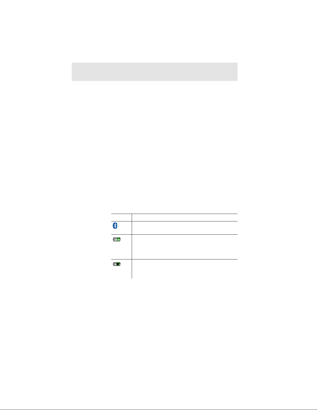
4.3.3. Display
1 Status bar (dark grey background):
• Warning symbol (only if there is a device error, display
of error in instrument diagnosis menu), otherwise:
Instrument designation.
• Symbol (only if data are stored in the temporary
memory).
• Display of date and time.
• Indication of Bluetooth
capacity of the battery:
Icon Feature
2 Info field of register tabs: Indication of selected
Address / Location, chosen fuel, chosen measurement type
3 Selection field for functions (chosen function appears against a
white background, unavailable functions are identified by grey
characters) or display of measuring values.
4 Function display for function keys.
4 Product description
®
status, power supply and remaining
blue symbol = Bluetooth® on,
grey symbol = Bluetooth
Battery operation
®
off
Indication of remaining capacity of the rech. batt.
by colour and filling degree of the battery symbol
(green = 5-100 %, red = < 5 %)
Mains operation
Indication of remaining capacity of battery: see
above
23
Find Quality Products Online at: [email protected]
www.GlobalTestSupply.com
Page 23

4 Product description
4.3.4. Device connections
1 Probe socket
2 Flue gas socket
3 Mains unit socket
4 Pressure socket
4.3.5. Interfaces
1 USB interface
2 PS2-interface
3 Infrared interface (IrDA)
4 Bluetooth interface (optional)
24
Find Quality Products Online at: [email protected]
www.GlobalTestSupply.com
Page 24

4.3.6. Components
4 Product description
1 Rechargeable battery
2 Measuring gas pump
3 Slot for CO-sensor or COlow-sensor
4 Slot O2-sensor
5 Slot NO-sensor or NOlow-sensor
6 Additional filter
25
Find Quality Products Online at: [email protected]
www.GlobalTestSupply.com
Page 25

4 Product description
4.3.7. Carrying strap (0440 0581)
To secure the carrying strap:
> Remove the sealing caps from the sides of the housing.
Fix the sealing caps on the inside of the service cover:
1. Place the measuring instrument on its front.
2. Pick the service cover up at the markings (arrows) using your
index finger and thumb and press gently to release the lock.
3. Fold up the service cover and remove it.
4. Secure the sealing caps in the two holders on the inside of the
service cover (1).
5. Attach the service cover and engage it in place.
> Engage the carrying strap clip in the fixing eyelets on the sides
of the device. Note the guide groove, the strap must point
"down" (2).
26
Find Quality Products Online at: [email protected]
www.GlobalTestSupply.com
Page 26

4.4. Modular flue gas probe
1 Removable filter chamber with window and particle filter
2 Probe handle
3 Connecting cable
4 Connector plug for measuring instrument
5 Probe module lock release
6 Probe module
4 Product description
27
Find Quality Products Online at: [email protected]
www.GlobalTestSupply.com
Page 27

5 First steps
5 First steps
5.1. Commissioning
The measuring instrument is supplied with a rechargeable battery
already fitted.
> Charge the battery fully before using the measuring instrument,
5.2. Getting to know the product
see Charging batteries, page 29.
5.2.1. Mains unit / rechargeable battery
If the mains unit is connected, the measuring instrument is
5.2.1.1. Changing the battery
automatically powered from the unit.
✓ The measuring instrument must not be connected to a mains
socket via the mains unit. The instrument must be switched off.
Change the rechargeable battery within 3 minutes so that device
settings (e.g. date / time) are not lost.
1. Place the measuring instrument on its front.
2. Remove the service cover: Take hold of it at the markings
(arrows) using the index finger and thumb, press slightly, fold
up and remove.
3. Open the battery lock: Press the grey key and push in direction
of arrow.
4. Remove the battery and insert a new rechargeable battery.
Only use the Testo rechargeable battery 0515 0107!
5. Close the battery lock: Press the grey key and push against
direction of arrow until the battery engages.
6. Attach the service cover and engage it in place.
28
Find Quality Products Online at: [email protected]
www.GlobalTestSupply.com
Page 28

5.2.1.2. Charging batteries
The rechargeable battery can only be charged at an ambient
temperature of ±0...+35 °C. If the battery has been discharged
completely, the charging time at room temperature is approx. 5-6
hrs.
5 First steps
Charging in the measuring instrument
1. Connect the plug of the mains unit to the mains unit socket on
the measuring instrument.
2. Connect the mains plug of the mains unit to a mains socket.
- The charging process will start. The charge condition will be
shown in the display. The charging process will stop
automatically when the battery is fully charged.
Charging in the charging station (0554 1087)
> Refer to the documentation enclosed with the charging station.
Battery care
> Do not fully exhaust rechargeable batteries.
> Store rechargeable batteries only in charged condition and at
low temperatures, but not below 0 °C (best storage conditions
with a charge level of 50-80 %, at an ambient temperature of
10-20 °C, recharge completely before use).
> For longer breaks you should discharge and recharge the
batteries every 3- months. Trickle charging should not exceed 2
days.
5.2.1.3. Mains operation
1. Connect the plug of the mains unit to the mains unit socket on
the measuring instrument.
2. Connect the mains plug of the mains unit to a mains socket.
- The measuring instrument is powered by the mains unit.
- If the measuring instrument is switched off and a rechargeable
battery is inserted, the charging process will start automatically.
Switching the measuring instrument on has the effect of
stopping battery charging and the measuring instrument is then
powered via the mains unit.
For longer measurements that are mains-operated, Testo
recommends using a combustion air temperature probe
with connecting cable. Self-heating of the instrument
during mains operation may influence the combustion air
temperature measurement with a mini ambient air probe.
29
Find Quality Products Online at: [email protected]
www.GlobalTestSupply.com
Page 29
5 First steps
5.2.2. Connecting probes / sensors
Probe/sensor detection at the flue gas socket is carried out
continuously. New probes are recognised automatically.
Connect a probe to the probe socket before switching on
the measuring instrument or start sensor detection
manually after changing the probe: [Options] → Sensor
detection.
Connecting flue gas probes / gas pressure adapters / temperature adapters
> Insert the connector plug into the flue gas socket and lock by
slightly turning it clockwise (bayonet lock).
There must be no more than one extension lead (0554
1201) between measuring instrument and flue gas probe.
30
Connecting other sensors
> Insert the connector plug of the probe into the probe socket.
Find Quality Products Online at: [email protected]
www.GlobalTestSupply.com
Page 30

5.2.3. Switching on
> press [ ] .
- The start screen is displayed (duration: about 5 s).
- If the voltage supply was interrupted for a longer period: The
menu Date / Time is opened.
- The pressure sensors are set to zero.
- There is a device error: The Error Diagnosis is displayed.
- The menu Measurements is displayed.
5.2.4. Calling up a function
1. Select function: [▲], [▼].
- The chosen function appears in a frame.
2. Confirm selection: [OK].
- The chosen function is opened.
5.2.5. Entering values
Some functions require values (numbers, units, characters) to be
entered. Depending on the function that is chosen, the values are
entered via either a list field or an input editor.
List field
5 First steps
1. Select the value to be changed (numerical value, unit): [▲],
[▼], [◄], [►] (depending on the selected function).
2. Press [Edit] .
3. Set value: [▲], [▼], [◄], [►] (depending on the selected
function).
4. Confirm the entry: [OK].
5. Repeat steps 1 and 4 as required.
6. Save the entry: [Finished].
31
Find Quality Products Online at: [email protected]
www.GlobalTestSupply.com
Page 31

5 First steps
Input editor
1. Select the value to be changed (character): [▲], [▼], [◄], [►].
2. Accept value: [OK].
Options:
> Toggle between upper / lower case characters:
Select Ι← ABC→&$/ →Ι : [▲], [▼] → [ABC→&$/].
> Position the cursor in the text:
Select Ι
← ABC→&$/ →Ι : [▲], [▼] → [Ι←] or
[
→Ι].
> Delete character before or after the cursor:
Select
← next → : [▲], [▼] → [←] or [→].
3. Repeat steps 1 and 2 as required.
4. Save the entry: Select
← next → : [▲], [▼] → [Next].
5.2.6. Show graphic
1 Current measuring value
2 End time of the displayed period.
The time is not displayed if no measuring value was recorded for
this period.
32
Find Quality Products Online at: [email protected]
www.GlobalTestSupply.com
Page 32

5.2.7. Printing / saving data
Data are printed out via the function key [ ] or the menu Options.
Data are saved via the menu Options. The menu Options is
accessed via the left function key and is available in many different
menus.
Assignment of the right function key with the function Save or
Print, see Assigning the right function key page 39 .
Only measuring values, which have a display field in the
measurement view assigned, will be saved / printed out.
The measurement data can be printed out parallel to the
saving process, while a measurement program is running.
To be able to transmit data via infrared or Bluetooth interface to a
report printer, the printer to be used must have been activated, see
Activating the printer:, page 43.
5.2.8. Remembering data (clipboard)
With the help of the clipboard measuring results from various
measurement types can be combined to a common record, which
can then be printed out (see above). Data are saved to the
clipboard via the menu Options and the command Clipboard.
If there are data in the clipboard, the status bar shows the symbol
.
If there are data in the clipboard and the command Print is
triggered, all data in the clipboard will be printed out.
Only one set of measuring data can be recorded per measurement
type (e.g. Flue Gas or Draught). Repetitive saving of test data of
one measurement type overwrites the previously saved data. When
changing the measurement place or the fuel, the clipboard is
deleted.
5 First steps
5.2.9. Confirming an error message
If an error occurs, an error message is shown in the display.
> Confirming an error message: [OK].
Errors which have occurred and have not yet been rectified are
indicated by a warning symbol ( ) in the header.
Not yet rectified error messages can be displayed in the menu
Error Diagnosis, see Instrument diagnosis, page 37.
33
Find Quality Products Online at: [email protected]
www.GlobalTestSupply.com
Page 33
5 First steps
5.2.10. Switching off
Unsaved measuring values will be lost when the flue gas
analyser is switched off.
> Press [ ] .
- Possibly: The pump starts and the sensors are rinsed until the
switch-off thresholds (O2 > 20 %, other measurement
parameters < 50 ppm) are reached. The maximum rinsing
period is 3 minutes.
- The measuring instrument switches off.
5.3. Address/Location
All measuring values can be saved under the currently active
location. Measuring values that have not been saved are lost when
the measuring instrument is switched off!
Addresses and locations can be created, edited, copied and
enabled. Addresses and locations (incl. protocols) can be deleted.
Call up function:
> [ ] → Address/Location → [OK].
There are various options for opening address.
1. Edit search setting: [Edit].
2. Select search setting: [▲], [▼] → [OK].
Possible settings:
• Show all: All address/location are displayed.
• Search: A search text only brings up address/location that
contain characteristics of the search text.
• Filter: Individual letters or numbers can be selected. All data
beginning with the relevant letter/number is displayed.
The initial letter is the determining factor for the filter
function, and this can only be selected individually. The
search function can also be used to find a series of several
letters within the address!
3. Carry out search according to search setting: [Search]
34
Find Quality Products Online at: [email protected]
www.GlobalTestSupply.com
Page 34

5 First steps
Show all
1. Select address: [▲], [▼].
2. Show details: [Details].
3. Enable a location: select the location → [OK].
- The location is activated.
> Open measurements menu: press [OK] again.
Search
1. Edit search criteria: [►] → [Edit].
2. Select search criteria: [▲], [▼] → [OK].
Possible options:
• Contact person
• Address
• Town/city
• Postcode
• Street
- The selected criterion is displayed.
3. Call up entry field for search text: [►] or [▼]
> Enter search text → [Finished]
Do not use the special character * as a placeholder.
Filter
1. Edit search criteria: [Edit].
2. Select search criteria: [▲], [▼] → [OK].
Possible options:
• Contact person
• Address
• Town/city
• Postcode
• Street
- The selected criterion is displayed.
3. Enable tab: [▼]
4. Select the required tab: [▲], [▼] and sometimes [◄], [►]→
[Filter].
- The search result for the relevant letter or number is displayed.
35
Find Quality Products Online at: [email protected]
www.GlobalTestSupply.com
Page 35

5 First steps
Create a new measuring location:
A location is always created under an address.
1. Select the address in which the location is to be created.
2. [Options] → New/Location → [OK].
3. Enter values or make settings.
4. Finalise the entry: [Finished].
Other location options:
> [Options] → Edit location: make changes to an existing
location.
> [Options] → Copy location: make a copy of an existing
location in the same address.
> [Options] → Delete location: delete an existing location.
Create new address:
1. [Options] → New address → [OK].
2. Enter values or make settings.
3. Finalise the entry: [Finished].
Other address options:
• Edit address: make changes to an existing folder.
• Copy address: make a copy of an existing folder.
• Delete address: delete an existing folder, including the
locations created therein.
• Delete All addresses: delete all existing folders, including the
locations created in them.
5.4. Measurement records
Calling up the function:
> [ ] → Measurement Records → [OK].
There are various options for opening protocols, see
Address/Location, page 34
Displaying a record:
1. Choose the required record from the detailed view.
2. Print [Data].
36
Find Quality Products Online at: [email protected]
www.GlobalTestSupply.com
Page 36

Printing all records for a location:
1. Select measuring location: [▲], [▼]
2. Start printout: [ ].
- All records for the location are printed out.
Options:
> [Options] → Show Graphic: Display saved record data as
graphic.
> [Options] → Print Data: Transmit data of the chosen record to
a record printer.
> [Options] → Delete Record: Delete the chosen record.
> [Options] → Number of Lines: Change the number of
measuring values per display page.
> [Options] → Delete all Records: Delete all saved records for a
location.
5.5. Instrument diagnosis
Important operating values and instrument data are displayed. A
gas path check (testo 330-2 LL) can be carried out. The status of
the sensors and any device errors not yet rectified can be
displayed.
Calling up the function:
> [ ] → Instrument Diagnosis → [OK].
or
> [ i ].
5 First steps
Carrying out a gas path check (testo 330-2 LL)
1. Gas Path Check → [OK]
2. Place the black sealing cap on the tip of the flue gas probe.
- The pump flow is displayed. If the volumetric flow rate is less
than 0.02 l/min, the gas paths are not leaking.
3. End of check: [OK].
Viewing device errors:
> Error Diagnosis → [OK].
- Unrectified errors are displayed.
> View next / previous error: [▲], [▼].
37
Find Quality Products Online at: [email protected]
www.GlobalTestSupply.com
Page 37
5 First steps
View sensor diagnosis:
1. > Sensor Diagnosis → [OK].
2. Select sensor. [▲], [▼].
- The status of the sensor is indicated by a lamp.
A sensor is able to recover. It is therefore possible that the
sensor status indication changes from yellow to green or
from red to yellow.
View instrument information:
> Device Information → [OK].
- Information is displayed.
38
Find Quality Products Online at: [email protected]
www.GlobalTestSupply.com
Page 38
6 Using the product
6.1. Performing settings
6.1.1. Assigning the right function key
The right function key can have a function from the Options menu
assigned to it. The menu Options is accessed via the left function
key and is available in many different menus. This assignment is
only valid for the currently opened menu / the opened function.
✓ A menu / function is opened in which the Options menu is
6.1.2. Instrument settings
displayed on the left function key.
1. Press [Options] .
2. Select option: [▲], [▼].
Depending on the menu / function from which the Options menu
was opened, the following functions are available.
3. Assign the selected function to the right function key: Press
[Config. Key].
It is assumed that the contents of the chapter First steps
(see First steps, page 28) are known.
Calling up a function:
> [ ] → Device Settings.
see First steps, page 28
6 Using the product
6.1.2.1. Readings display
The parameters / units and the display representation (number of
readings displayed per display page) can be set.
The settings are only valid for the currently chosen measurement
type, which is indicated by the symbol in the info field.
Total overview of selectable parameters and units (available
selection depends on the chosen measurement type):
Display Parameter
FT
AT
ltemp
Pump
39
Find Quality Products Online at: [email protected]
www.GlobalTestSupply.com
Flue gas temperature
Combustion air temperature
Instrument temperature
Pumping capacity
Page 39

6 Using the product
Display Parameter
O2
CO2
CO
uCO
NO
NOx
λ
amCO
amCO2
O2ref
Edrft
E-ΔP external differential pressure (micro pressure
ExAir
Ratio
η+ Efficiency under due consideration of the heat
η Efficiency without consideration of the heat value
Dew/a
Oxygen
Carbon dioxide
Carbon monoxide
Carbon monoxide undiluted
Nitrogen monoxide
Nitrogen oxide
Air ratio
Ambient carbon monoxide
Ambient carbon dioxide
Oxygen reference
external draught (micro pressure probe)
probe)
Air ratio
Poison index
value range
range
Flue gas dew point temperature
40
Calling up the function:
> [ ] → Instrument Settings → [OK] → Readings Display →
[OK]
Changing parameter / unit in a line:
1. Select the line where you want to position the selected
measurement parameter: [▲], [▼] → [Edit]
2. Select the parameter: [▲], [▼] → [OK]
3. Select the unit: [▲], [▼] → [OK]
4. Save changes: [OK]
- The measurement parameter is now in the selected position on
the reading display.
Find Quality Products Online at: [email protected]
www.GlobalTestSupply.com
Page 40

Options:
> [Options] → Number of Lines: Change the number of
measuring values per display page.
> [Options] → Insert Empty Lines: Insert the empty line before
the selected line.
> [Options] → Delete Line: Delete the selected line.
> [Options] → Factory Setting: Reset the readings display to
factory setting
6.1.2.2. Alarm limits
Alarm limits can be set for several display parameters. An audible
alarm signal is triggered when the alarm limit is reached.
Calling up the function:
> [ ] → Instrument Settings → [OK] → Alarm Limits → [OK]
Switching alarm signals on / off, changing alarm limits:
1. Select function or parameter: [▲], [▼] → [Edit].
2. Set parameter: [▲], [▼] and partly [◄], [►] → [OK].
3. Save changes: [Finished].
> Reset the enabled value to the factory setting: [Standard].
6.1.2.3. Units
The units used for parameters in configuration menus can be set.
Calling up the function:
> [ ] → Instrument Settings → [OK] → Units → [OK]
6 Using the product
Adjustable units
Parameter Unit
Altitude m, ft
Pressure mbar, hPa
1. Select the line: [▲], [▼]→ [Edit].
2. Select the unit to be changed: [▲], [▼] → [OK].
41
3. Confirm the entry: [Finished].
Find Quality Products Online at: [email protected]
www.GlobalTestSupply.com
Page 41

6 Using the product
6.1.2.4. Date / time
Date, time mode and time can be set.
Calling up the function:
> [ ] → Instrument Settings → [OK] → Date/Time → [OK]
Setting date/time:
1. Select parameter: [◄], [▲], [▼] → [Edit].
2. Set parameter: [▲], [▼] and partly [◄], [►] → [OK].
3. Save changes: [Save].
6.1.2.5. Energy management
Automatic instrument shutdown (Auto-Off) and switching off of the
display light in battery operation can be set.
Calling up the function:
> [ ] → Instrument Settings → [OK] → Energy Management
→ [OK]
Making settings:
1. Select function or parameter: [▲], [▼] → [Edit].
2. Set parameter: [▲], [▼] and partly [◄], [►] → [OK].
3. Save changes: [Finished].
6.1.2.6. Display brightness
The intensity of the display illumination can be set.
Calling up the function:
> [ ] → Instrument Settings → [OK] → Display Brightness →
[OK]
Performing settings
> Set parameter: [◄], [►] → [OK].
6.1.2.1. Choose measurement type
Individual measurement types can be shown or hidden. These are
displayed or hidden accordingly under Measurement options.
Call up function:
> [ ] → Device settings → [OK] → Choose measurement
type → [OK].
42
Find Quality Products Online at: [email protected]
www.GlobalTestSupply.com
Page 42
Show or hide measurement types:
1. Select measurement type: [▲], [▼]
2. Enable / disable measurement type: [ ] (enabled), [ ]
(disabled)
3. Save selection: [Finished].
6.1.2.2. Printer
The headers (lines 1-3) and the footers for the printout can be set.
The printer that is used can be activated.
Calling up the function:
> [ ] → Instrument Settings → [OK] → Printer → [OK]
Activating the printer:
1. Select Printer → [OK].
2. Select the printer: [▲], [▼] → [OK].
- The printer is activated and the menu Printer is opened.
Setting the print text:
1. Print text → [OK].
2. Select function: [▲], [▼] → [Edit].
> Enter values for Line 1, Line 2, Line 3 and the Footnote
> Print out system data and/or customer data: [ ]
3. Save the entry: select [Finished].
6 Using the product
The printer 0554 0543 can only be selected after the
Bluetooth
Bluetooth
®
-interface has been activated, see
®
, page 43.
6.1.2.3. Bluetooth®
This menu is only available if the instrument is equipped with
Bluetooth. The Bluetooth module can be switched on / off.The relay
43
Find Quality Products Online at: [email protected]
can now be tested.
Calling up the function:
> [ ] → Instrument Settings → [OK] → Bluetooth → [Edit].
Making settings:
> Set parameter → [OK].
www.GlobalTestSupply.com
Page 43

6 Using the product
6.1.2.4. Language
The menu language can be set. The number of available
languages depends on the activated country version, see Country
version, page 44.
Calling up the function:
> [ ] → Instrument Settings → [OK] → Language → [OK]
Activating the language:
> Select the language → [OK].
see Country version, page 44
6.1.2.5. Country version
Changing the country version may alter the basis for calculation
and therefore also the displayed measurement parameters, fuels,
fuel parameters and calculation formulas.
The selection of the country version influences the menu languages
that can be enabled.
Calling up the function:
> [ ] → Instrument Settings → [OK] → Country Version →
[OK]
This action can be password protected. A password is
specified in the menu Password Protection, see
Password protection, page 45.
Possibly:
> Enter the password: [Enter] → Enter password → [Next] →
[OK].
Setting the country version:
1. Select the country version: [▲], [▼] → [OK].
2. Confirm the confirmation request: Yes → [OK]
- The system is restarted.
see Password protection, page 45
44
Find Quality Products Online at: [email protected]
www.GlobalTestSupply.com
Page 44

6.1.2.6. Password protection
The password protection is only valid for functions identified by the
following symbol: or .
Password protection can be activated / deactivated, the password
can be changed.
To deactivate the password protection change the password to
0000 (factory setting).
Calling up the function:
> [ ] → Instrument Settings → [OK] → Password Protection
→ [OK]
Possibly:
> Enter the currently valid password:
[Enter] → Enter password → [Next] → [OK].
Changing the password:
1. [Edit].
2. Enter the new password → [Next].
3. [Edit].
4. Enter the new password again to confirm → [Next].
5. Save changes: [Finished].
6 Using the product
6.1.3. Sensor settings
6.1.3.1. NO2 addition
The NO2 addition parameter can be set.
The setting of the NO2-addition can be password protected, see
Password protection, page 45.
Calling up the function:
> [ ] → Sensor Settings → NO2 Addition → [Edit].
Possibly:
> Enter the password: [Enter] → Enter password → [Next] →
[OK].
Setting the NO
> Set parameter → [OK].
45
addition:
2
Find Quality Products Online at: [email protected]
www.GlobalTestSupply.com
Page 45

6 Using the product
6.1.3.2. O2 reference
The O2 reference value can be set.
The setting of the O2 reference value can be password protected,
see Password protection, page 45.
Calling up the function:
> [ ] → Sensor Settings → O2 Reference→ [Edit].
Possibly:
> Enter the password: [Enter] → Enter password → [Next] →
[OK].
Setting the O
> Set parameter → [OK].
reference:
2
6.1.3.3. Sensor protection
Protection limits can be set to protect the sensors against overload.
Sensor protection switch-off is available for the following sensors:
CO, NO.
The sensor protection is activated when the threshold is exceeded.
• testo 330-1 LL: Switch-off.
• testo 330-2 LL: Dilution, if exceeded again: Switch-off.
To deactivate sensor protection the thresholds must be set to 0
ppm.
Calling up the function:
> [ ] → Sensor Settings → Sensor Protection → [OK].
Setting sensor protection thresholds:
1. Select parameter: [Edit].
2. Set parameter → [OK].
3. Save changes: [Finished].
46
Find Quality Products Online at: [email protected]
www.GlobalTestSupply.com
Page 46
6.1.3.4. Recalibration / adjustment
WARNING
CO and NO sensors can be recalibrated and adjusted.
For recalibration / adjustment Testo recommends the use of the
calibration adapter 0554 1205.
If obviously unrealistic readings are displayed, the sensors
should be checked (calibrated) and, if required, adjusted.
Have the recalibration / adjustment carried out by a
qualified service centre approved by Testo.
Adjustments made with low gas concentrations can lead to
accuracy deviations in the upper measuring ranges.
Calling up the function:
> [ ] → Sensor Settings → Recalibration → [OK].
Possibly:
> Enter the password: [Enter] → Enter password → [Next] →
[OK].
- Gas zeroing (30 s).
6 Using the product
Performing recalibration / adjustment:
Dangerous gases
Danger of poisoning!
> Observe safety regulations / accident prevention regulations
when handling test gas.
> Use test gases in well ventilated rooms only.
1. Connect the calibration adapter to the flue gas socket.
2. Select the parameter: [▲], [▼] → [OK].
3. [Edit] → Enter the test gas concentration (nominal value).
4. Attach the connecting line of the test gas bottle to the
calibration adapter.
5. Apply test gas to the sensor.
6. Start recalibration: [Start].
7. Accept the nominal value once the actual value is stable
(adjustment): [OK].
-orAbort (no adjustment): [esc].
8. Save changes: [Finished].
47
Find Quality Products Online at: [email protected]
www.GlobalTestSupply.com
Page 47
6 Using the product
6.1.4. Fuels
The fuel can be selected. The fuel-specific coefficients and limits
can be set.
Apart from the pre-configured fuels, 10 more customer specific
fuels can be configured. Fuel parameter, see
Calling up the function:
> [ ] → Fuels → [OK].
Activating fuels:
> Select the fuel → [OK].
- The fuel is activated and the main menu is opened.
Setting coefficients:
1. Select the fuel → [Coeff.].
2. Select the coefficients: [Edit].
Possibly:
> Enter the password: [Enter] → Enter password → [Next] →
[OK].
3. Set values → [OK].
4. Save changes: [Finished].
In order to maintain the measuring accuracy of the
instrument one must choose or configure the correct fuel.
Correct representation of measuring results is only assured
if the threshold values for the ideal range of the
corresponding measurement task have been set correctly.
The pre-set threshold values are typical values for the
selected system type and the chosen type of fuel.
Setting limits:
1. Select limit → [Edit].
2. Set values → [OK].
3. Save changes: [Finished].
48
Find Quality Products Online at: [email protected]
www.GlobalTestSupply.com
Page 48

6.1.5. Programs
Five measuring programs for different measurement types can be
configured and activated. The measuring programs serve the
purpose of saving and representing measuring sequences. After
the end of the measuring process the readings of a measuring
program are automatically saved in a record.
Only one measuring program can be activated in the instrument.
Calling up the function:
> [ ] → Programs → [OK].
Activating / deactivating a program:
> Select the program: [▲], [▼] → [Enable] or [Disable].
- When activating a program: The program is activated and the
measurement type matching the program is opened.
6 Using the product
Configuring the program:
The measuring cycle takes 1s and cannot be changed.
An activated program cannot be configured.
1. Select the program: [▲], [▼] → [Edit].
2. Select parameters program name, measurement type, gas
phase: [▲], [▼] → [Edit].
3. Set parameters or enter values: [▲], [▼] and partly [◄], [►]→
[OK].
6.2. Measuring
4. Save changes: [Finished].
6.2.1. Preparing for measurement
It is assumed that the contents of the chapter First steps
(see First steps, page 28) are known.
6.2.1.1. Zeroing phases
Measuring the ambient air temperature (AT)
If no combustion air temperature probe is connected, the
temperature measured by the thermocouple of the flue gas probe
during the zeroing phase is used as the combustion air
temperature. All dependent parameters are calculated using this
value. This method of measuring combustion air temperature is
sufficient for systems dependent on ambient air. However, ensure
49
Find Quality Products Online at: [email protected]
www.GlobalTestSupply.com
Page 49
6 Using the product
that the flue gas probe is near the intake duct of the burner during
the zeroing phase.
If a combustion air temperature probe is connected, the combustion
air temperature is measured continuously via this probe.
Gas zeroing
When the instrument is switched on the measurement menu is
opened and the gas sensors are zeroed.
Draught / pressure zeroing
The pressure sensors are zeroed when a pressure measuring
function is called up.
testo 330-1 LL: The flue gas probe must be in the open air
during the zeroing phase!
testo 330-2 LL: The flue gas probe can be in the flue gas
duct even during the zeroing phase, if a separate VTsensor is plugged in.
testo 330-1 LL: The flue gas probe must be in the open air
during the zeroing phase / the instrument must not be
pressurised during zeroing!
testo 330-2 LL: The flue gas probe can be in the flue gas
duct even during the zeroing phase, if a separate VTsensor is plugged in. The pressure socket of the instrument
must be free (i.e. unpressurized, not closed).
6.2.1.2. Using the modular flue gas probe
50
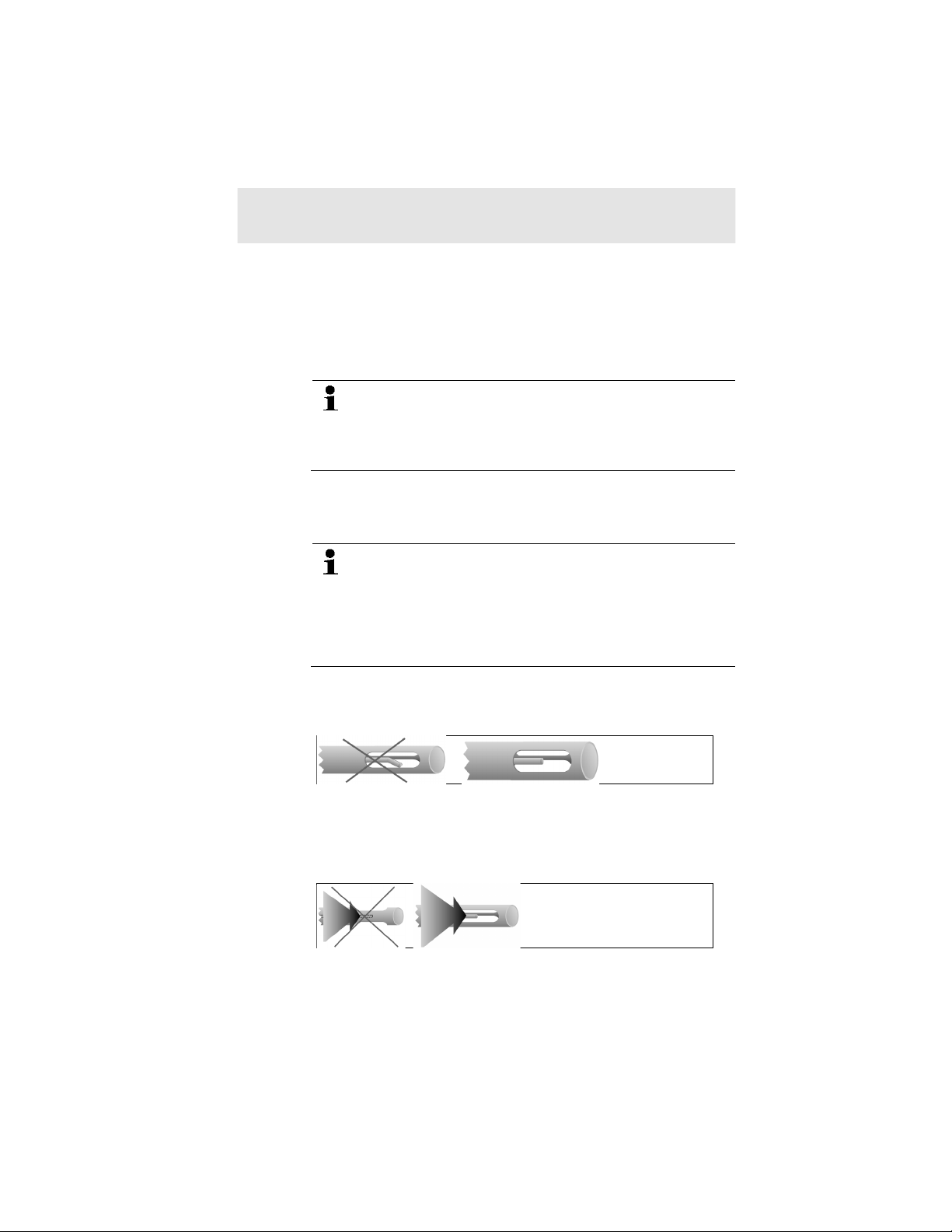
Checking the thermocouple
The thermocouple of the flue gas probe must not lie against the
probe cage.
> Check before use. Bend the thermocouple back if necessary.
Aligning the flue gas probe
The flue gas must be able to flow freely past the thermocouple.
> Align the probe by turning it as required.
Find Quality Products Online at: [email protected]
www.GlobalTestSupply.com
Page 50
6 Using the product
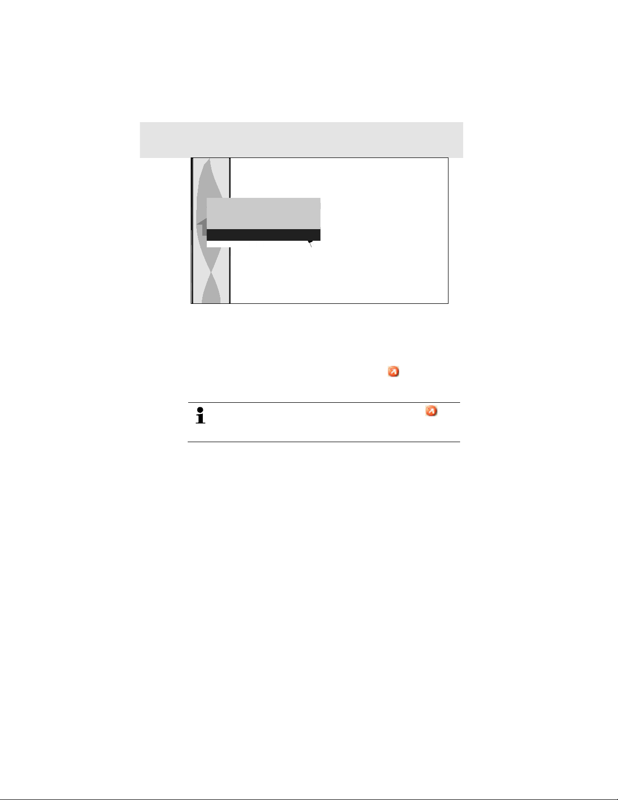
The tip of the probe must be in the hot spot of the flue gas flow.
> Align the flue gas probe in the flue gas duct so that the tip is in
the hotspot (area of the highest flue gas temperature). As a
visual aid, the display shows the current temperature with a
green bar. The red marking indicates the maximum measured
temperature during the hotspot search. If the symbol
appears, the temperature is outside the measuring range of the
flue gas probe.
The measuring value of the red marking and the
symbol can only be cancelled by restarting the flue gas
menu.
6.2.1.3. Configuring the reading display
Only those parameters and units, which are activated in the reading
display, appear in the reading display, the saved measurement
protocols and the record printouts.
> Before performing measurements set up the reading display in
such a way, that the required parameters and units are
activated, see Readings display, page 39.
6.2.1.4. Setting location and fuel
Before carrying out measurements, the measurement location and
the fuel must be correctly selected, see Address/Location, page 34
51
and Fuels, page 48.
Find Quality Products Online at: [email protected]
www.GlobalTestSupply.com
Page 51
6 Using the product
6.2.2. Flue gas
To achieve usable measurement results, the measurement
period of a flue gas measurement should be approx. 3 min
and the measuring instrument should display stable
measured values.
Calling up the function:
1. [ ] → Measurements → [OK] → Flue Gas → [OK].
2. Select the fuel → [OK].
Performing the measurement:
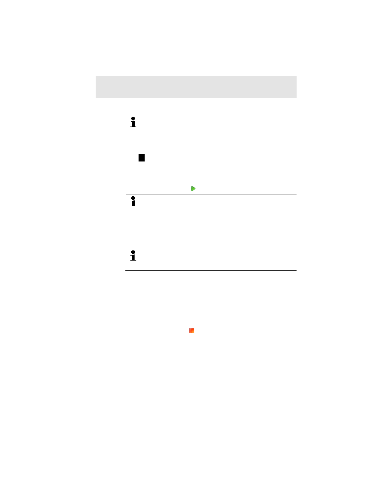
1. Start measurement: [ ].
If a separate measurement of CO undiluted has not yet
been carried out, this value is calculated using the readings
of the flue gas probe and is updated continuously.
If CO undiluted has already been measured separately, the
value obtained is adopted.
- The readings are displayed.
> [Options] → Draught measure start/stop
The draught measurement option is only available if the
measurement parameter Draught is enabled in the reading
display.
- Draught measurement zeroing
- Draught measurement begins automatically
> Hold the draught measurement value displayed: [Drgt stop]
- The measurement stops automatically.
- The readings are automatically displayed and saved in a record.
Option
Restart the draught measurement: [Drgt start]
2. Quit measurement: [ ].
Options
> [Options] → Clipboard: Data are saved to the clipboard
> [Options] → Delete clipboard: Any data saved to the clipboard
is deleted.
> [Options] → Save: The readings are saved in a record.
> [Options] → Show Graphic: The readings are displayed in
form of a line graph.
52
Find Quality Products Online at: [email protected]
www.GlobalTestSupply.com
Page 52
6 Using the product
> [Options] → Configure Graphic: The measurement
parameters to be represented (max. 4) can be displayed ( ) or
hidden ( ).
> [Options] → Draught measure start/stop: The measurement
view is opened and a draught measurement can be carried out.
> [Options] → Flue Gas Matrix: The readings are displayed as
flue gas matrix, see below.
> [Options] → Number of Lines: Change the number of
measuring values per display page.
> [Options] → Accept measuring values from 315-3:
Ambient CO/CO2 values measured with the testo 315-3 can be
accepted by the testo 330. Data is transferred via Bluetooth® or
via the IrDA interface.
For data transfer via Bluetooth®, the testo 315 - 3 and the
testo 330 - 2 must have this option, otherwise data is
transferred via the IrDA interface.
✓ A measurement was carried out with the testo 315-3.
✓ testo 330-2 is on.
✓ Data transfer at the testo 315-3 has been enabled.
- The testo 330 accepts the instrument-specific information
and measurement data sent from the testo 315-3. The
measurement data is displayed under ppm AmbCO or ppm
AmbCO2.
> [Options] → Recalibrate: The gas sensors are set to zero.
> [Options] → Measurement view: (This function is not available
during a measurement): The readings display menu is opened.
Show flue gas matrix
This function is only available if the measurement parameter CO
has been activated in the readings display.
Calling up the function:
✓ The flue gas function is opened.
> [Options] → Flue Gas Matrix:
Options
> [Options] → Clipboard: Data are saved to the clipboard:
> [Options] → Delete clipboard: Any data saved to the clipboard
is deleted.
> [Options] → Save: The readings are saved in a record.
53
Find Quality Products Online at: [email protected]
www.GlobalTestSupply.com
Page 53

6 Using the product
> [Options] → Show Graphic: The readings are displayed in
form of a line graph.
> [Options] → Show Numerical Values: Data are displayed as
numerical values.
> [Options] → System Type: (This function is not available
during a measurement). Set the system type to be able to
configure the ideal zone (green) of the flue gas matrix, using the
limits pre-configured for each system type.
> [Options] → Reset Graphic: The displayed graphical values
are deleted.
> [Options] → Limits: (This function is not available during a
measurement). Enter limits to be able to configure the ideal
zone (green) of the flue gas matrix.
> [Options] → CO + O2 or CO + CO2: Choose which parameter
should be assigned to the x-axis of the display matrix (O2 or
CO2).
> [Options] → Measurement view: (This function is not available
3.
6.2.3. Draught-Measurement
during a measurement). Open the readings display menu.
Calling up the function:
✓ A flue gas probe must be connected.
54
1. [ ] → Measurements → [OK] → Draught → [OK].
Performing the measurement:
The pressure socket of the instrument must be free (i.e.
unpressurized, not closed).
Do not measure for longer than 5 min, as the drift of the
pressure sensor means that the readings could be outside
the tolerance limits.
1. Start measurement: [ ].
- Draught zeroing.
2. Position the flue gas probe in the hot spot (area of the highest
flue gas temperature).
The display showing the maximum measured flue gas
temperature (FT max) helps when positioning the probe.
- The reading is displayed.
3. Quit measurement [ ].
Find Quality Products Online at: [email protected]
www.GlobalTestSupply.com
Page 54

Options:
> [Options] → Clipboard: Data are saved to the clipboard.
> [Options] → Delete clipboard: Any data saved to the clipboard
is deleted.
> [Options] → Save: The readings are saved in a record.
> [Options] → Show Graphic: The readings are displayed in
form of a line graph.
> [Options] → Configure Graphic: The measurement
parameters to be represented (max. 4) can be displayed ( ) or
hidden ( ).
> [Options] → Measurement view: (This function is not available
4.
6.2.4. Micro pressure probe
during a measurement): The readings display menu is opened.
The following measurements can be performed using the micro
pressure probe (0638 0330):
• Ext-Draught
• Ext-Delta-P Single meas.
• Ext-Delta Program
5.
See instruction manual for micro pressure probe.
6 Using the product
6.2.5. CO undiluted
Calling up the function:
✓ A multi-hole probe (0554 5762) must be connected.
> [ ] → Measurements → [OK] → CO undiluted → [OK].
Performing the measurement:
1. Start measurement: [ ]
- The reading is displayed.
2. Quit measurement: [ ]
Options:
> [Options] → Clipboard: Data are saved to the clipboard.
> [Options] → Delete clipboard: Any data saved to the clipboard
is deleted.
> [Options] → Save: The readings are saved in a record.
> [Options] → Show Graphic: The readings are displayed in
form of a line graph.
55
Find Quality Products Online at: [email protected]
www.GlobalTestSupply.com
Page 55
6 Using the product
WARNING
6.2.6. Smoke No. / HCT
Calling up the function:
> [ ] → Measurements → [OK] → Smoke No. / HCT → [OK].
The parameters Smoke No. and Oil derivatives are only
available for oil fuels.
Determining smoke tester no. / smoke nos. / oil derivative with the smoke pump and entering manually:
1. Select parameter → [Edit].
2. Enter data or values → [Next] or [OK].
Determining smoke tester no. / smoke nos. / oil derivative with the smoke tester testo 308 and transferring wireless:
- The testo 308 must be in data transfer mode ( lights up).
> [Options] → t308.
- The values recorded by the smoke tester are transferred to the
testo 330.
Entering the heat carrier temperature:
> Heat carrier → [Edit] → Enter value → [OK].
Options:
> [Options] → Clipboard: Data are saved to the clipboard
> [Options] → Delete clipboard: Any data saved to the clipboard
is deleted.
> [Options] → Save: The readings are saved in a record.
> [Options] → Reset values: The entered values are deleted.
6.2.7. Differential pressure
Dangerous mixture of gases
Danger of explosions.
> Make sure there are no leaks between the sampling point and
the measuring instrument.
56
> Do not smoke or use naked flames during measurement.
Do not measure for longer than 5 min, as the drift of the
pressure sensor could have the effect that the readings are
outside the tolerance limits.
Find Quality Products Online at: [email protected]
www.GlobalTestSupply.com
Page 56

6 Using the product
✓ The gas pressure set (0554 1203) must be connected.
Calling up the function:
> [ ] → Measurements → [OK] → Differential Pressure →
[OK].
Performing the measurement:
✓ At the start of the measurement, the instrument's pressure
socket must be unpressurised (e.g. instrument must not be
connected to the system to be tested), as the pressure sensor
has to be zeroed first.
1. Start measurement: [ ].
- Pressure zeroing.
2. Connect a silicone hose to the testo 330-2 and the system to be
tested.
- The reading is displayed.
3. Quit measurement: [ ].
Options:
> [Options] → Clipboard: Data are saved to the clipboard
> [Options] → Delete clipboard: Any data saved to the clipboard
is deleted.
> [Options] → Save: The readings are saved in a record.
> [Options] → Show Graphic: The readings are displayed in
form of a line graph.
> [Options] → Measurement view: (This function is not available
during a measurement): The readings display menu is opened.
6.2.8. Differential temperature
✓ The differential temperature set (0554 1204) must be
connected.
Calling up the function:
> [ ] → Measurements → [OK] → Differential Temperature→
[OK].
Performing the measurement:
1. Start measurement: [ ].
- The readings and the calculated differential temperature
(T1 T2) are displayed.
2. Quit measurement: [ ].
57
Find Quality Products Online at: [email protected]
www.GlobalTestSupply.com
Page 57

6 Using the product
Options:
> [Options] → Clipboard: Data are saved to the clipboard.
> [Options] → Delete clipboard: Any data saved to the clipboard
is deleted.
> [Options] → Save: The readings are saved in a record.
> [Options] → Show Graphic: The readings are displayed in
form of a line graph.
> [Options] → Measurement view: (This function is not available
during a measurement): The readings display menu is opened.
6.2.9. O2 air
✓ An O2 dual wall clearance probe (0632 1260) must be
connected.
Calling up the function:
> [ ] → Measurements → [OK] → O2 Air→ [OK].
Performing the measurement:
1. Start measurement: [ ].
- The reading is displayed.
2. Quit measurement: [ ].
58
Options:
> [Options] → Clipboard: Data are saved to the clipboard.
> [Options] → Delete clipboard: Any data saved to the clipboard
is deleted.
> [Options] → Save: The readings are saved in a record.
> [Options] → Show Graphic: The readings are displayed in
form of a line graph.
Find Quality Products Online at: [email protected]
www.GlobalTestSupply.com
Page 58

6.2.10. Gas flow
The function is only available if the chosen fuel is a gas.
Calling up the function:
> [ ] → Measurements → [OK] → Gas Flow→ [OK].
Performing the measurement:
1. Start measurement: [ ].
- The measuring duration is displayed.
2. When the adjusted gas flow is reached: [ ].
- The calculated gas flow and the gas burner capacity (in kW) are
displayed.
Options:
> [Options] → Clipboard: Data are saved to the clipboard.
> [Options] → Delete clipboard: Any data saved to the clipboard
is deleted.
> [Options] → Save: The readings are saved in a protocol.
> [Options] → Enter heating value: heating value can be set.
> [Options] → Units setting: the unit for gas flow, heating value,
duration and GasPgr can be changed.
6 Using the product
6.2.11. Oil flow
The function is only available if the chosen fuel is an oil.
Calling up the function:
> [ ] → Measurements → [OK] → Oil Flow → [OK].
Performing the measurement:
1. Select the parameters Oil Flow (of the oil nozzle) and Oil
Pressure (no effect on calculation): [▲], [▼] → [Edit].
2. Enter values. [▲], [▼] and partly [◄], [►]→ [OK].
- The calculated oil burner capacity (in kW) is displayed.
Options:
> [Options] → Clipboard: Data are saved to the clipboard
> [Options] → Delete clipboard: Any data saved to the clipboard
is deleted.
> [Options] → Save: The readings are saved in a protocol.
> [Options] → Unit settings: The unit for the oil flow can be
changed (kg/h > gal/h or gal/h > kg/h).
59
Find Quality Products Online at: [email protected]
www.GlobalTestSupply.com
Page 59

6 Using the product
6.2.12. CO ambient
✓ An ambient CO probe (recommended) or a flue gas probe must
be connected.
Cigarette smoke influences the measurement by more than
50 ppm. The breath of a smoker influences the
measurement by about 5 ppm.
When using an ambient CO probe, note that:
The direction of flow of the gas has an effect on the
accuracy of the measurement. Frontal flow onto the probe
leads to higher readings. The best measurement results are
achieved when the probe is moved gently backwards and
forwards.
When using the ambient CO probe and the flue gas probe,
note that:
The probe must be in the open air (CO-free) during the
zeroing phase!
Calling up the function:
> [ ] → Measurements → [OK] → CO Ambient → [OK].
Performing the measurement:
1. Start measurement: [ ].
- The measurement starts and the measuring value is displayed
graphically (trend display).
- An audible alarm signal is triggered when the alarm limit is
reached.
2. Quit measurement: [ ].
3. Confirm the message: [OK].
Options:
> [Options] → Clipboard: Data are saved to the clipboard.
> [Options] → Delete clipboard: Any data saved to the clipboard
is deleted.
> [Options] → Save: The readings are saved in a record.
> [Options] → A-Thresh.: The alarm limits menu is opened.
60
Find Quality Products Online at: [email protected]
www.GlobalTestSupply.com
Page 60
6.2.13. CO2 ambient
✓ An ambient CO2 probe (0632 1240) must be connected.
In order to obtain correct readings, it is imperative to enter
the prevailing absolute pressure. This can be entered
directly (Pressure Absolute), or it is automatically
calculated when entering Altitude and barometric pressure
(Pressure Barom.).
Calling up the function:
> [ ] → Measurements → [OK] → CO2 Ambient → [OK].
Performing the measurement:
1. Select parameter → [Edit].
2. Enter values. [▲], [▼] and partly [◄], [►]→ [OK].
3. Start measurement: [ ].
4. Quit measurement: [ ].
- The ambient CO2 value is displayed.
Options:
> [Options] → Clipboard: Data are saved to the clipboard.
> [Options] → Delete clipboard: Any data saved to the clipboard
is deleted.
> [Options] → Save: The readings are saved in a record.
> [Options] → Show Graphic: The readings are displayed in
form of a line graph.
> [Options] → Alarm Limit: The alarm limits menu is opened.
> [Options] → Edit. Values for adjustable parameters can be
edited.
> [Options] → Sensor detection
detected.
> [Options] → Measurement view: (This function is not available
during a measurement): The redings display menu is opened..
6 Using the product
: newly inserted sensor is
61
Find Quality Products Online at: [email protected]
www.GlobalTestSupply.com
Page 61
6 Using the product
6.2.14. Automatic furnaces
With the help of the readout adapter for automatic furnaces
(0554 1206) status data and error messages can be read out of
compatible automatic furnaces, see also documentation on readout
adapter. The range of data which can be read out depends on the
type of the automatic furnace.
Calling up the function:
1. Connect the readout adapter to the instrument (PS2 interface)
and to the automatic furnace (use adapter ring if necessary).
2. [ ] → Measurements → [OK] → Automatic Furnace →
[OK].
- The data are read from the automatic furnace. Depending on
the automatic furnace, the data are updated at the latest every
30 s.
The values are saved in a measuring report or transferred
to a pocket PC / PC, together with the measuring values of
a flue gas measurement.
Reading out current status data:
The current data are displayed after a connection has been set up
to the automatic furnace. The following data are displayed with the
help of symbols:
62
Component Status ON Status OFF
Air controller
Motor
Valve 1
Valve 2
Flame
Ignition
Oil prewarmer
Options
> [Options] → Clipboard: Data are saved to the clipboard.
> [Options] → Delete clipboard: Any data saved to the clipboard
is deleted.
> [Options] → Save: The readings are saved in a record.
> [Options] → Adapter Information: Type and version of
readout adapter are displayed.
Find Quality Products Online at: [email protected]
www.GlobalTestSupply.com
Page 62
> [Options] → Identification: Information about manufacturer
and type of automatic furnace
> [Options] → Statistics: Display of error statistics.
Automatic furnaces are equipped with a circular buffer
memory: Error messages are overwritten when the error log
is full. The fault that has occurred last is at position 1 in the
error list.
> [Options] → Fault: Display of faults.
6.2.15. Solid fuel measurement
The solid fuel measurement program is only available with
instruments that come with the CO sensor (not COlow). For
measurements in accordance with the 1st Federal Immission
Control Ordinance (BImSchV), a CO,H2-compensated sensor
(0393 0101) is required.
The function is only available if the activated fuel is solid
fuel and adapter 0600 9765 has been connected.
Calling up the function:
> [ ] → Measurement options → [OK] → Solid fuel → [OK].
Performing the measurement:
1. Select parameters gas phase, meas. rate or stability time: [▲],
[▼] → [Change].
2. Enter values. [▲], [▼]and partly [◄], [►] → [OK].
3. [Finished].
4. Insert the flue gas probe into the exhaust pipe and position it in
the hot spot.
5. Start measurement: [ ]
- The stabilisation phase (minimum 2 min) progresses. After this
the measuring phase starts automatically (minimum 5 min).
The stabilisation phase can be interrupted early.
> Press [Next].
- The measuring phase starts automatically.
- The measuring result is displayed after the measuring phase
has been completed.
6 Using the product
63
Find Quality Products Online at: [email protected]
www.GlobalTestSupply.com
Page 63
6 Using the product
Options:
> [Options] → Clipboard: Data are saved to the clipboard.
> [Options] → Delete clipboard: Data in the clipboard are
deleted.
> [Options] → Save: The readings are saved in a record.
> [Options] → Show Graphic: The readings are displayed in
form of a line graph.
> [Options] → Configure Graphic: The measurement
parameters to be represented (max. 4) can be displayed ( ) or
hidden ( ) werden.
> [Option] → Measurement view: (This function is not available
during a measurement): The readings display menu is opened.
6.2.16. Gas pipe tests
Calling up the function:
> [ ] → Measurements → [OK] → Gas Pipe Tests → [OK].
6.2.16.1. Tightness test 1
Leak test on gas pipes acc. to DVGW-TRGI 2008
worksheet G600
The leak test (using air or inert gas, e.g. CO2 or N2) is used
for acceptance testing of newly routed or remedied pipes.
The test is performed at the pipe, including the fittings,
without gas installations and corresponding control and
safety equipment. For this test the line must be pressurised
with 150 mbar, whereby this pressure must remain constant
for 10 minutes.
This applies to lines < 100 l. For larger line volumes, the
stability time and measurement period should be adjusted
in accordance with DVGW-TRGI 2008 worksheet G600.
> Connect the connecting plug of the hose pressure connection
set (0554 1203) to the pressure test set (0554 1213), plug the
pressure adapter onto the flue gas socket and lock in place by
slightly turning it clockwise (bayonet lock).
Performing the measurement:
✓ The pressure socket of the instrument must be free (i.e.
unpressurized, not closed).
1. Tightness Test 1 → [OK].
- Pressure zeroing.
2. Select parameter: [▲], [▼] → [Edit].
64
Find Quality Products Online at: [email protected]
www.GlobalTestSupply.com
Page 64
3. Set parameters or enter values: [▲], [▼] and partly [◄], [►]→
[OK].
4. Pressurise the system.
Once the pressure has built up, a stability time specified by
DVGW-TRGI 2008 should be observed to ensure that any
possible pressure fluctuations are not recorded in the
measurement. The relevant standard provides more
detailed information.
5. Start measurement: [ ].
- The stability time will run. After this the measuring phase starts
automatically.
> End stability time and measurement early: [Next].
- The readings are displayed when measurement has been
completed.
6.2.16.2. Tightness test 2
• Follow DVGW-TRGI 2008, worksheet G624.
• Pressure Absolute (parameter of location) must strictly
be entered to obtain correct readings. If this is unknown
it is recommended to use the value 966hPa
(corresponds with 1013 hPa barometric, altitude 400 m)
To enter the values:
> [ ] → Measurements → [OK] → Gas Pipe Tests →
[OK] → [Tightness Test 2] → [Fold./Meas.] →
[Options] → Edit Location.
> Plug the connecting plug of the hose connection set
(0554 1203) into the flue gas socket and lock in place by turning
it slightly clockwise (bayonet lock).
6 Using the product
Performing the measurement:
✓ The pressure socket of the instrument must be free (i.e.
unpressurized, not closed).
1. Tightness Test 2 → [OK].
2. Select parameter: [▲], [▼] → [Edit].
3. Set parameters or enter values: [▲], [▼] and partly [◄], [►]→
[OK].
Three circular diameters and three pipe lengths can be
entered, which are then used to calculate three partial
volumes. The pipe volume is calculated by adding these
three partial volumes.
65
Find Quality Products Online at: [email protected]
www.GlobalTestSupply.com
Page 65

6 Using the product
4. [measurement].
- Pressure zeroing.
5. Pressurise the system.
6. Start measurement: [ ].
- The stability time will run. After this the measuring phase starts
automatically.
> End stability time and measurement early: [Next].
- The readings and Result Tightness Test 2 are displayed when
measurement has been completed.
7. [Edit] → Select test result: [▲], [▼] → [OK].
6.2.16.3. Let By Test
> Plug the connecting plug of the hose connection set
(0554 1203) into the flue gas socket and lock in place by turning
it slightly clockwise (bayonet lock).
Performing the measurement:
✓ The pressure socket of the instrument must be free (i.e.
unpressurized, not closed).
1. Let By Test → [OK].
- Pressure zeroing.
2. Select parameter: [▲], [▼] → [Edit].
3. Set parameters or enter values: [▲], [▼] and partly [◄], [►]→
[OK].
4. Pressurise the system.
5. Start measurement: [ ].
- The stability time will run. After this the measuring phase starts
automatically.
> End stability time and measurement early: [Next].
- The readings and Result Let By Test are displayed when
measurement has been completed.
6. [Edit] → Select test result: [▲], [▼] → [OK].
66
Find Quality Products Online at: [email protected]
www.GlobalTestSupply.com
Page 66
6.2.16.4. Leak detection
In gas leak detection no measurement is made, but a gas detection
is performed.
✓ A gas leak probe (0632 3330) must be connected.
You must also refer to the documentation that comes with
the gas leak probe.
Calling up the function:
> Leak Detection→ [OK].
Performing the detection:
> Set the gas type to be detected and perform gas leak testing by
following the instructions described in the documentation of the
gas leak probe.
1. Start detection: [ ].
- The gas concentration is displayed, if it exceeds the limit an
alarm signal will sound.
Options:
> [Options] → Save: the readings are saved in a record.
> [Options] → Show Graphic: The readings are displayed in
form of a line graph.
> [Options] → Alarm Limit: (This function is not available during
a measurement): Adjusting alarm limits.
> [Options] → Alarm Signal: (This function is not available
during a measurement): Alarm signal disable/enable.
> [Options] → Zeroing Probe: Perform zeroing.
> [Options] → Sensor detection: newly inserted sensor is
detected.
2. End detection: [ ].
6 Using the product
67
Find Quality Products Online at: [email protected]
www.GlobalTestSupply.com
Page 67

6 Using the product
6.3. Transferring data
6.3.1. Report printer
To be able to transmit data via infrared or Bluetooth interface to a
Testo report printer, the printer to be used must have been
activated, see Printer, page 43.
Printing out data takes place via [Print] or [ ]. The function is only
available if a printout is possible.
Representation of the available characters per line is
limited on the printout. Thus, the unit mg/KWh is displayed
on the printout as mg/k.
6.3.2. PC / Pocket PC
Data transfer to a PC can take place via USB, IrDA or Bluetooth®.
Data transfer to a Pocket PC can take place via IrDA or Bluetooth
You must also refer to the documentation that comes with the
software.
®
.
68
Find Quality Products Online at: [email protected]
www.GlobalTestSupply.com
Page 68
7 Maintaining the product
,
7 Maintaining the product
7.1. Cleaning the measuring instrument
> If the housing of the measuring instrument is dirty, clean it with
a damp cloth. Do not use any aggressive cleaning agents or
solvents! Mild household cleaning agents and soap suds may
be used.
7.2. Replacing sensors
A slot bridge (0192 1552) must be inserted in slots which
are not equipped with a sensor. Used sensors must be
disposed of as hazardous waste!
✓ The instrument must be switched off.
1. Place the measuring instrument on its front.
2. Remove the service cover: Take hold of it at the markings
(arrows) using the index finger and thumb, press slightly, fold
up and remove.
3. Pull hose connections from the faulty sensor / bridge.
4. Remove the faulty sensor / bridge from the slot.
> For NO-sensor: Remove the auxiliary circuit board.
Do not remove the auxiliary circuit board for the NOsensor until immediately before installation. Do not
leave the sensor without auxiliary circuit board for
longer than 15 min.
5. Install new sensor / new bridge in the slot.
6. Plug the hose connections on sensor / bridge.
7. Attach the service cover and engage it in place.
After replacing an O2 sensor, wait for an equalisation
period of 60 min to elapse before using the instrument
again.
When retrofitting a sensor the associated measurement
parameter and unit must be enabled, see Readings display
page 39.
69
Find Quality Products Online at: [email protected]
www.GlobalTestSupply.com
Page 69

7 Maintaining the product
7.3. Recalibrating / adjusting sensors
See Sensor settings, page 45.
7.4. Replacing additional filter
The additional filter provides added protection should problems
occur with the particle filter in the flue gas probe. The additional
filter is very rarely contaminated if the measuring instrument is used
normally.
> Check the additional filter (visually) periodically for
contamination and replace it if necessary.
1. Place the measuring instrument on its front.
2. Remove the service cover: Take hold of it at the markings
(arrows) using the index finger and thumb, press slightly, fold
up and remove.
3. Loosen the additional filter from the hose connection.
4 Plug the new filter (0133 0010) into the hose connection.
5. Attach the service cover and engage it in place.
70
Find Quality Products Online at: [email protected]
www.GlobalTestSupply.com
Page 70

7 Maintaining the product
7.5. Cleaning the modular flue gas probe
✓ Disconnect the flue gas probe from the measuring instrument
prior to cleaning.
1. Release the probe catch by pressing the key on the probe
handle and remove the probe module.
2. Blow compressed air through the flue gas ducts in probe
module and probe handle (see illustration). Do not use a brush!
3. Fit a new probe module on the probe handle and engage it in
place.
7.6. Replacing the probe module
✓ Disconnect the flue gas probe from the measuring instrument
prior to cleaning.
1. Press the key on the top of the probe handle and remove the
probe module.
71
Find Quality Products Online at: [email protected]
2. Plug in the new probe module and engage it in place.
www.GlobalTestSupply.com
Page 71
7 Maintaining the product
CAUTION
7.7. Changing the thermocouple
1. Release the probe catch by pressing the key on the probe
handle and remove the probe module.
2. Remove the thermocouple plug-in head from the socket using a
screwdriver and pull the thermocouple out of the probe shaft.
3. Keep inserting the new thermocouple into the probe shaft until
the connection head clicks into place.
4. Fit a new probe module on the handle and engage in place.
7.8. Condensate container
The fill level of the condensate trap can be read from the markings
on the condensate trap. A warning message ( , red flashing light)
is displayed if the fill level in the condensate trap reaches 90 %.
The fill level of the condensate trap can be read from the markings.
72
Draining the condensate trap
The condensate consists of a weak mix of acids. Avoid skin
contact. Make sure that the condensate does not run over
the housing.
Condensate entering the gas path.
Damage to sensors and flue gas pump!
> Do not empty the condensate trap while the flue gas pump is in
operation.
1. Unlock the condensate trap and pull it vertically off the
measuring box.
Find Quality Products Online at: [email protected]
www.GlobalTestSupply.com
Page 72
7 Maintaining the product
2. Open the condensate outlet on the condensate trap: Pull out
approx. 5 mm against the stop.
3. Let the condensate run out into a sink.
4. Wipe off any drops still on the condensate outlet with a cloth
and close the condensate outlet.
The condensate outlet must be completely closed
(marking), otherwise measuring errors could be caused by
infiltrated air.
7.9. Checking / replacing the particle filter
Checking the particle filter:
Check the particle filter of the modular flue gas probe periodically
for contamination: check visually by looking through the window
of the filter chamber.
Replace the filter if there are signs of contamination.
Replacing the particle filter:
The filter chamber may contain condensate.
1. Open the filter chamber: Turn gently anti-clockwise.
2. Remove the filter plate and replace it with a new one (0554
3385).
3. Attach the filter chamber and lock it. Turn gently clockwise.
73
Find Quality Products Online at: [email protected]
www.GlobalTestSupply.com
Page 73

8 Tips and assistance
8 Tips and assistance
8.1. Questions and answers
Question Possible causes / solution
Rechargeable battery low > Switch to mains operation.
Measuring instrument
switches automatically off
or cannot be switch on
Batteries / rechargeable batteries
empty.
> Charge rechargeable batteries or
switch to mains operation.
Displayed battery capacity
seems to be faulty
Rechargeable battery was repeatedly
not fully discharged/charged.
> Discharge rechargeable battery
(until measuring instrument
switches off automatically) and
then charge fully.
Error message: Pump
flow too high
Gas outlet blocked
> Make sure that the gas outlet is
clear.
Error message: Sensor
protection active
The shutdown limit of the CO sensor
was exceeded.
> Remove the probe from the stack.
Error message: Printing
not possible
• With printer 0554 0543: Bluetooth
interface not activated.
• Wrong printer activated.
• Printer switched off.
• Printer outside wireless
transmission range.
> Activate Bluetooth interface, see
Bluetooth
> Activate printer used, see Printer,
page 43.
• Switch on printer.
> Move printer within wireless
transmission range.
If we could not answer your question, please contact your dealer or
®
, page 43.
74
Find Quality Products Online at: [email protected]
www.GlobalTestSupply.com
Page 74

8.2. Accessories and spare parts
8 Tips and assistance
Printer
Description Article no.
Infrared high-speed printer 0554 0549
Bluetooth® printer, incl. rechargeable battery and
0554 0553
charging adapter
Spare thermal paper for printer (6 rolls) 0554 0568
Modular flue gas probes
Description Article no.
Modular flue gas probe 180 mm, 500 °C,
0600 9760
thermocouple 0.5 mm, probe shaft diameter: 8mm
Modular flue gas probe 300 mm, 500 °C,
0600 9761
thermocouple 0.5 mm, probe shaft diameter: 8mm
Modular flue gas probe 180 mm, 500 °C,
0600 9762
thermocouple 0.5 mm, probe shaft diameter: 6mm
Modular flue gas probe 300 mm, 500 °C,
0600 9763
thermocouple 0.5 mm, probe shaft diameter: 6mm
Flexible flue gas probe, length 330 mm,
0600 9764
Tmax. 180 °C, short-term 200 °C, bending radius
max. 90° for measurements at difficult to access
locations
Probe modules / accessories for modular flue gas probes
Description Article no.
Probe shaft module 180 mm, 500 °C, thermocouple
0554 9760
0.5 mm, probe shaft diameter: 8 mm
Probe shaft module 300 mm, 500 °C, thermocouple
0554 9761
0.5 mm, probe shaft diameter: 8 mm
Probe shaft module 180 mm, 500 °C, thermocouple
0554 9762
0.5 mm, probe shaft diameter: 6 mm
Probe shaft module 300 mm, 500 °C, thermocouple
0554 9763
0.5 mm, probe shaft diameter: 6 mm
Probe shaft module 300 mm, 1,000 °C,
0554 8764
thermocouple 1.0 mm, probe shaft diameter: 6 mm
75
Find Quality Products Online at: [email protected]
www.GlobalTestSupply.com
Page 75

8 Tips and assistance
Description Article no.
Probe shaft module 700 mm, 1,000 °C,
thermocouple 1.0 mm, probe shaft diameter: 6 mm
Spare thermocouple for module 0554 9760,
0554 9762
Spare thermocouple for module 0554 9761,
0554 9763
Spare thermocouple for module 0554 8764 0430 8764
Spare thermocouple for module 0554 8765 0430 8765
Cone, 8 mm, steel 0554 3330
Cone, 6 mm, steel 0554 3329
Multi-hole probe shaft, length 300 mm, Ø 8 mm, for
CO averaging
Multi-hole probe shaft, length 180 mm, Ø 8 mm, for
CO averaging
Flexible probe shaft module 0554 9764
Hose extension 2.8 m, extension line probe instrument
Particle filter, 10 pcs. 0554 3385
0554 8765
0430 9760
0430 9761
0554 5762
0554 5763
0554 1202
76
Temperature sensor
Description Article no.
Ambient air temperature (AT) probe, 300 mm 0600 9791
Ambient air temperature (AT) probe, 190 mm 0600 9787
Ambient air temperature (AT) probe, 60 mm 0600 9797
Fast reaction surface sensor 0604 0194
Miniature ambient air sensor 0600 3692
Other probes / sensors
Description Article no.
O2 annular gap probe 0632 1260
Gas leak probe 0632 3330
Ambient CO probe 0632 3331
CO2 ambient probe (without connecting cable) 0632 1240
Find Quality Products Online at: [email protected]
www.GlobalTestSupply.com
Page 76
8 Tips and assistance
Description Article no.
Connecting cable for CO2 ambient probe, 1.5 m 0430 0143
Gas pressure set: Draught path adapter, silicone
0554 1203
hose 4 mm / 6 mm, reducing cones
Differential temperature set, 2 pipe wrap probes,
0554 1204
adapter
Smoke tester inc. oil, soot plates, for measuring soot
0554 0307
in flue gas
Retrofit sensors
Description Article no.
NO retrofit 0554 2151
Spare sensors
Description Article no.
O2 sensor 0393 0002
O2 sensor 0393 0051
O2 sensor H2 compensated 0393 0101
COlow sensor 0393 0103
NO sensor 0393 0151
NOlow sensor 0393 0152
Cases
System case with double floor (height:180 mm) for
0516 3301
instrument, probes and accessories
System case (height: 130 mm) for instrument,
0516 3300
probes and accessories
System case with tool pouch without contents 0516 0329
77
Find Quality Products Online at: [email protected]
www.GlobalTestSupply.com
Page 77

8 Tips and assistance
Other accessories
Description Article no.
Mains unit 0554 1096
Charger with spare rechargeable battery 0554 1103
Spare rechargeable battery 0515 0107
Readout adapter for automatic furnaces 0554 1206
Connecting cable instrument / PC 0449 0047
Aasyheat (PC configuration software) 0554 3332
Additional filter 0133 0010
Draught set 0554 3150
Fine pressure probe 0638 0330
Set of capillary hoses 0554 1215
Solid fuel measurement module with adapter and
0600 9765
probe shaft with sintered filter
Sintered filter for solid fuel measurement probe shaft 0133 0035
Filter material for condensate trap on solid fuel
0133 0012
measurement adapter
Pressure test set for gas line testing 0554 1213
Straight Pitot tube 0635 2050
ISO Calibration Certificate Flue Gas 0520 0003
78
For a complete list of all accessories and spare parts, please refer
to the product catalogues and brochures or
Find Quality Products Online at: [email protected]
www.GlobalTestSupply.com
Page 78

8.3. Updating the instrument software
you can download the
current instrument software (Firmware) for testo 330 (registration
required).
> Unplug the mains unit and switch off the testo 330.
1. Hold [▲] depressed.
2. Plug in the mains unit, keep [▲] depressed.
- The display shows Firmware update along the bottom edge.
3. Release [▲] .
4. Insert the connecting cable (0449 0047) into the USB-port on
the instrument, then connect it to the PC.
- Your PC recognises the testo 330 as a removable medium.
5. Copy the new file (ap330rel.bin) to the detected removable
medium.
- In the display the status bar progresses from left to right. This
process may take a few minutes.
6. Disconnect the connecting cable from the testo 330.
- After updating of the instrument software (Firmware) has been
completed the system will automatically reboot and is ready for
use.
8 Tips and assistance
79
Find Quality Products Online at: [email protected]
www.GlobalTestSupply.com
Page 79

0970 3311 en 07 V01.15 en_GB
Find Quality Products Online at: [email protected]
www.GlobalTestSupply.com
 Loading...