

Page 1
Instruction manual en
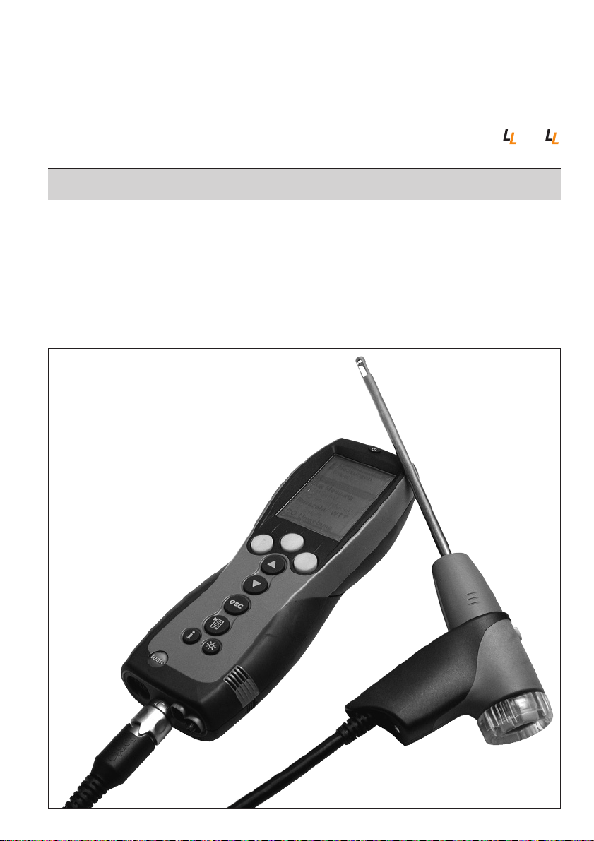
testo 330 -1, -2, -3 / testo 330-1 , -2
Flue gas analyser
Page 2
General notes
Please read this documentation through carefully and familiarise yourself with the
operation of the product before putting it to use. Keep this document to hand so that
you can refer to it when necessary.
The document describes the country-specific version D of the testo 330-1, -2, -3 and
testo 330-1LL, -2LL products.
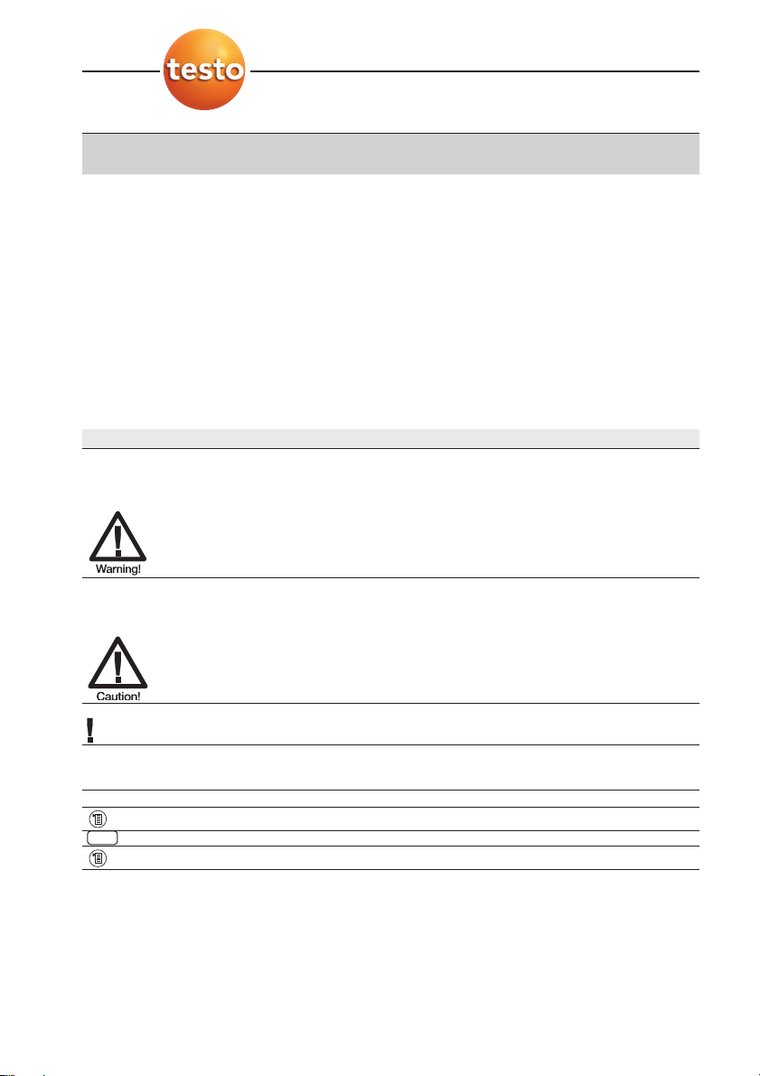
Identification
Symbol Meaning Comments
Warning advice: Warning! Read the warning advice carefully and take
Serious physical injury could be caused if the the specified precautionary measures!
specified precautionary measures are not taken.
Warning advice: Caution! Read the warning advice carefully and take
Slight physical injury or damage to equipment the specified precautionary measures!
could occur if the specified precautionary
measures are not taken.
Important. Please pay particular attention.
(testo 330-1) The description applies only for the -
instrument indicated: testo 330-1, -2, -3 /
testo 330-1LL, -2LL.
Tex t Text appears on the instrument’s display -
Key Press the key.
Function key with the function “OK”. Press function key.
➞ xyz Short form for operating steps. See
short form
, p. 3.
OK
General notes
2
Page 3
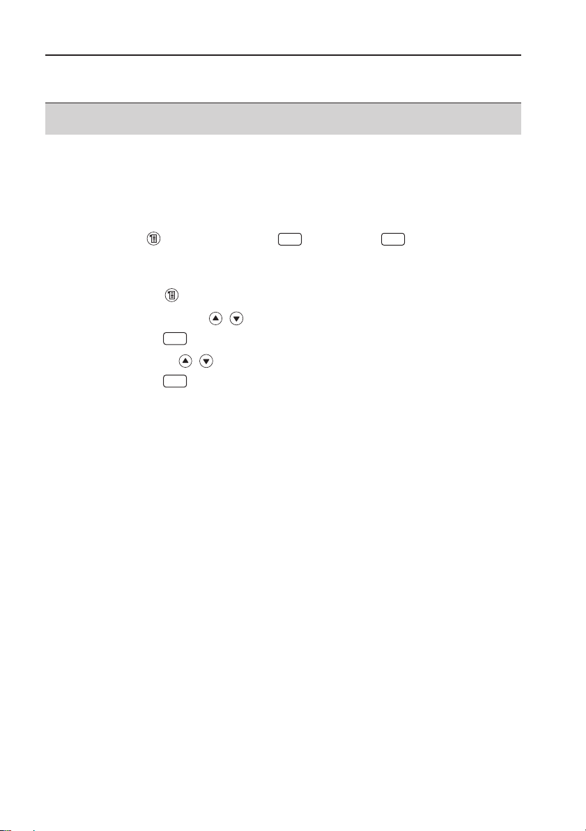
Short form
This document uses a short form for describing operating steps (e.g. calling up a
function).
Example: Calling up the Flue gas function
Short form: ➝
Measurements ➝➝Flue gas ➝
(1) (2) (3) (4) (5)
Steps required:
1 Open main menu: .
2 Select
Measurements menu: , .
3 Confirm selection: .
4 Select
Flue gas menu: , .
5 Confirm selection: .
OK
OK OK
OK
General notes
3
Page 4

Contents
See also
Functional overview
, p. 63.
General notes ........................................................................................2
Contents ................................................................................................4
A. Safety advice ........................................................................................7
B. Intended purpose ..................................................................................9
C. Product description ............................................................................10
C.1 Measuring instrument ..................................................................10
C.1.1 Overview ..................................................................................10
C.1.2 Keypad ....................................................................................11
C.1.3 Display ....................................................................................11
C.1.4 Device connections ..................................................................12
C.1.5 Interfaces ................................................................................13
C.1.6 Components ............................................................................13
C.1.7 Carrying strap / barcode pen holder ..........................................14
C.2 Modular flue gas probe ................................................................15
D. Commissioning ....................................................................................16
E. Operation ............................................................................................17
E.1 Mains unit / rechargeable battery ..................................................17
E.1.1 Changing the battery ..............................................................17
E.1.2 Charging batteries ....................................................................18
E.1.3 Operation with the mains unit ..................................................18
E.2 Probes / Sensors ..........................................................................19
E.2.1 Connecting probes / sensors ....................................................19
E.2.2 Replacing the probe module ....................................................20
E.3 Regular care ................................................................................20
E.3.1 Condensate trap ......................................................................20
E.3.2 Checking / replacing the particle filter ........................................21
Contents
4
Page 5

E.4 Basic operating steps ..................................................................21
E.4.1 Switching the measuring instrument on ....................................21
E.4.2 Calling up a function ................................................................22
E.4.3 Entering values ........................................................................22
E.4.4 Printing data ............................................................................23
E.4.5 Saving data ..............................................................................23
E.4.6 Confirming an error message ..................................................23
E.4.7 Scanning locations with the barcode pen ................................24
E.4.8 Switching the measuring instrument off ....................................24
E.5 Memory / Location ........................................................................25
E.6 Instrument diagnosis ..................................................................27
F. Configuration ......................................................................................28
F.1 Instrument settings ......................................................................28
F.1.1 Display edit ..............................................................................28
F.1.2 Printer ......................................................................................29
F.1.3 Alarm limits ..............................................................................30
F.1.4 Start Keys edit ........................................................................30
F.1.5 t315-3 Connect ........................................................................31
F.1.6 Communication ........................................................................32
F.1.7 Date / Time ..............................................................................32
F.1.8 Language ................................................................................32
F.2 Sensor settings ............................................................................33
F.3 Fuels ..........................................................................................34
G. Measuring ............................................................................................35
G.1 Preparing measurements ............................................................35
G.1.1 Zeroing phases ........................................................................35
G.1.2 Using the modular flue gas probe ............................................36
G.1.3 Configuring the reading display ................................................36
G.1.4 Set memory/location ................................................................36
Contents
5
Page 6

G.2 Measurements ............................................................................37
G.2.1 Flue gas ..................................................................................37
G.2.2 Draught ....................................................................................38
G.2.3 Fine pressure probe (accessory) ..............................................38
G.2.4 BImSchV (testo 330-3 / testo 330-2 LL) ..................................39
G.2.5 Solid fuel measurement (testo 330-2)........................................41
G.2.6 CO undiluted ............................................................................42
G.2.7 Smoke No. / HCT ....................................................................42
G.2.8 Differential pressure ..................................................................43
G.2.9 Differential temperature ............................................................44
G.2.10 O2 air ......................................................................................44
G.2.11 Gas flow rate ..........................................................................45
G.2.12 Oil flow rate ..............................................................................45
G.2.13 Leak detection ........................................................................46
G.2.14 Ambient CO ............................................................................46
G.2.15 Ambient CO2 ..........................................................................47
G.2.16 Burner control ..........................................................................48
I. Transfering data ..................................................................................50
H.1 Protocol printer ............................................................................50
H.2 PC / Pocket PC ............................................................................50
I. Care and maintenance ........................................................................51
I.1 Cleaning the measuring instrument ..............................................51
I.2 Replacing measuring cells ..........................................................51
I.3 Recalibrating measuring cells ......................................................52
I.4 Replacing additional filter ............................................................52
I.5 Cleaning the modular flue gas probe ............................................53
I.6 Changing the thermocouple ........................................................53
J. Questions and Answers ......................................................................54
K. Technical data ....................................................................................55
K.1 Standards and inspections ..........................................................55
K.2 Measuring ranges and accuracies ..............................................56
K.3 Other device data ........................................................................57
K.4 EC declaration of conformity ........................................................58
K.5 Principles of calculation ..............................................................59
K.5.1 Fuel parameters ......................................................................59
K.5.2 Calculation formulae ................................................................59
L. Accessories / Spare parts ....................................................................61
Functional overview ............................................................................63
Contents
6
Page 7
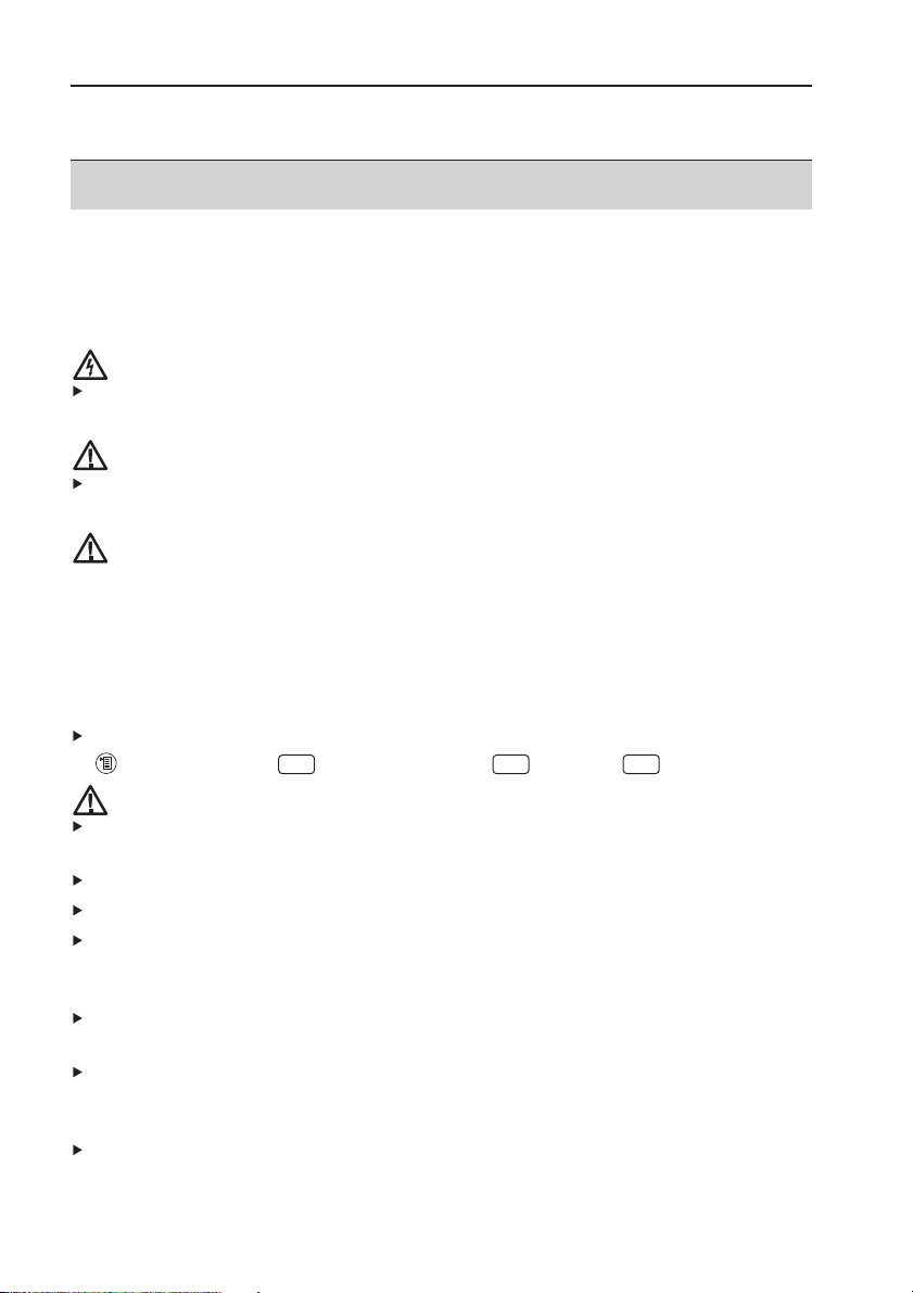
A. Safety advice
Avoid electrical hazards:
Never use the measuring instrument and probes to measure on or near live parts!
Protect the measuring instrument:
Never store the instrument/ measuring cells together with solvents (e.g. acetone). Do
not use any dessicants.
Product with Bluetooth
®
(Option)
Changes or modifications, which are not expressly approved by the responsible official
body, can lead to a withdrawal of operating permission.
Interference with data transfer can be caused by instruments which transmit on the
same ISM band, e.g. microwave ovens, ZigBee.
The use of radio connections is not allowed in e.g. aeroplanes and hospitals. For this
reason, the following point must be checked before entering:
Deactivate Bluetooth function:
➝
Inst’ settings ➝➝Communication ➝➝ IrDA ➝ .
Product safety / preserving warranty claims:
Operate the measuring instrument only within the parameters specified in the
technical data.
Handle the instrument properly and according to its intended purpose.
Never apply force!
Temperatures given on probes / sensors relate only to the measuring range of the
sensors. Do not expose handles and feeders to any temperatures in excess of 70 °C
unless they are expressly permitted for higher temperatures.
Open the measuring instrument only when this is expressly described in the
Operating Instructions for maintenance purposes.
Carry out only the maintenance and repair work that is described in the Operating
Instructions. Follow the prescribed steps exactly. For safety reasons, use only original
spare parts from Testo.
The testo 330 must be checked before commissioning for any visible damage. Do
not commission the testo 330 if there are signs of damage on the housing, mains unit
or supply lines. Electrical risk..
OK OK OK
A. Safety advice
7
Page 8

Any further or additional work must only be carried out by authorised personnel.
Testo will otherwise refuse to accept responsibility for the proper functioning of the
measuring instrument after repair and for the validity of certifications.
Ensure correct disposal:
Dispose of defective rechargeable batteries and spent batteries at the provided
collection points.
Send the measuring instrument directly to us at the end of its life cycle. We will
ensure that it is disposed of in an environmentally friendly manner.
A. Safety advice
8
Page 9

B. Intended purpose
This chapter describes the areas of application for which the measuring instrument is
intended.
The testo 330 is a handheld measuring device for the professional flue gas analysis of
furnace systems:
· Small furnaces (burning oil, gas, wood, coal)
· Low-temperature and condensing boilers
· Gas heaters
These systems can be adjusted using the testo 330 and checked for compliance with
the applicable limit values.
The measuring instrument is approved for measurements under the German regulations
on immissions protection (1. BImSchV).
The following tasks can also be carried out with the testo 330:
· Regulating the O
2
-, CO- and CO2-, NO-, NOxvalues in furnaces for the purpose of
ensuring optimal operation.
· Draught measurement.
· Measuring and regulating the gas flow pressure in gas heaters.
· Measuring and optimising the flow and return temperatures of heating systems.
· CO- and CO
2
environment measurement.
· Detection of CH
4
(methane) and C3H8(propane).
testo 330 should not be used:
· for continuous measurements
· as a safety (alarm) instrument
The testo 330 with the Bluetooth option may only be operated in countries in which it
is type approved (see Technical Data).
B. Intended purpose
9
Page 10
C. Product description
This chapter provides an overview of the individual components of the product.
C.1 Measuring instrument
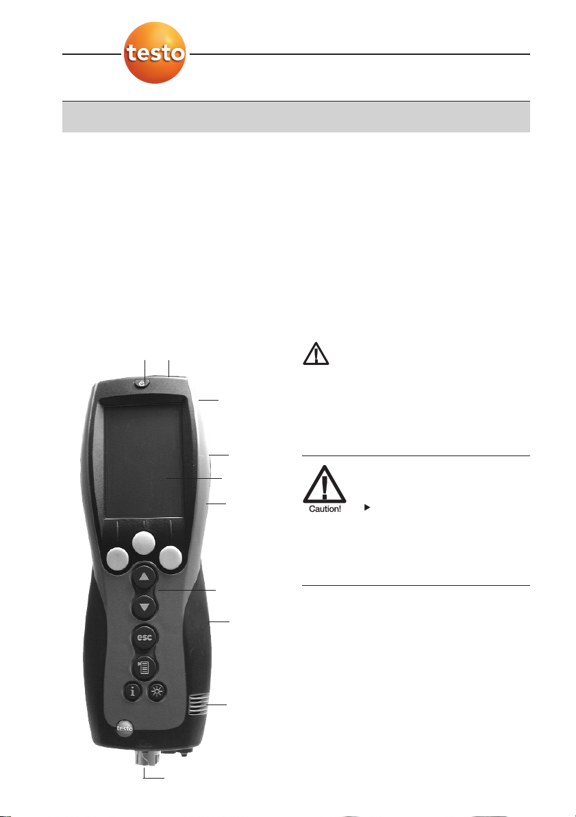
C.1.1 Overview
➀ Switch on / off
➁ Interfaces: USB, PS2, infrared
Do not direct infrared beam at
human eyes.
➂ Condensate trap (on rear)
➃ Fixing eyelets for carrying strap (left and
right)
➄ Display
➅ Magnetic holders (on rear)
Strong magnets
Damage to other magnets
Keep safe distance from
products which could be
damaged by magnets (e.g.
monitors, computers,
pacemakers, credit cards).
➆ Keypad
➇ Service cover (on rear)
➈ Gas outlet
➉ Unit connections: flue gas probe,
probe, pressure probe, mains unit
Placeholder:
Uebersicht.tif
C. Product description
C.1 Measuring instrument
10
➄
➅
➁
➀
➇
➆
➈
➉
➂
➃
Page 11
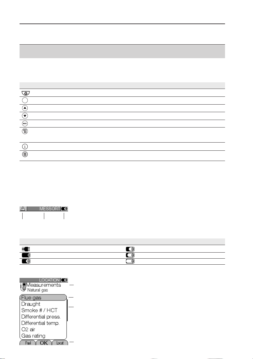
C.1.2 Keypad
Key Functions
Switch measuring instrument on / off
Function key (orange, 3x), relevant function is shown on the display
Scroll up, increase value
Scroll down, reduce value
Back, cancel function
Open Main menu: press briefly (changed settigs are stored, measurement values are carried over into the menu
Flue gas); open Measurements menu: press and hold down for 2s (changed settigs are stored, measurement
values are carried over into the menu Flue gas)
Open Inst’ diagnosis menu
Switch over display light: display light is permanently on or display light goes on for 10 seconds everytime a key
is activated.
C.1.3 Display
Depending on the menu that is active, the display shows a variety of elements.
Header (active in all views)
➀ Warning symbol (only if there is a device error; the
device error is displayed in the
Inst’ diagnosis
menu).
➁ Active location.
➂ Power supply symbol:
Symbol Characteristic Symbol Characteristic
Mains operation Rech. battery operation, capacity: 26-50%
Rech. battery operation, capacity: 76-100% Rech. battery operation, capacity: 6-25%
Rech. battery operation, capacity: 51-75% Rech. battery operation, capacity: 0-5%
Function select view
➀ Active menu, activated fuel
➁ Selection field for functions:
The chosen function is shown with a grey
background.
Unavailable functions are written in grey type.
➂ Scroll bar
➃ Function keys for entering commands
C. Product description
C.1 Measuring instrument
11
➀
➂
➃
➁
➀➁➂
Page 12
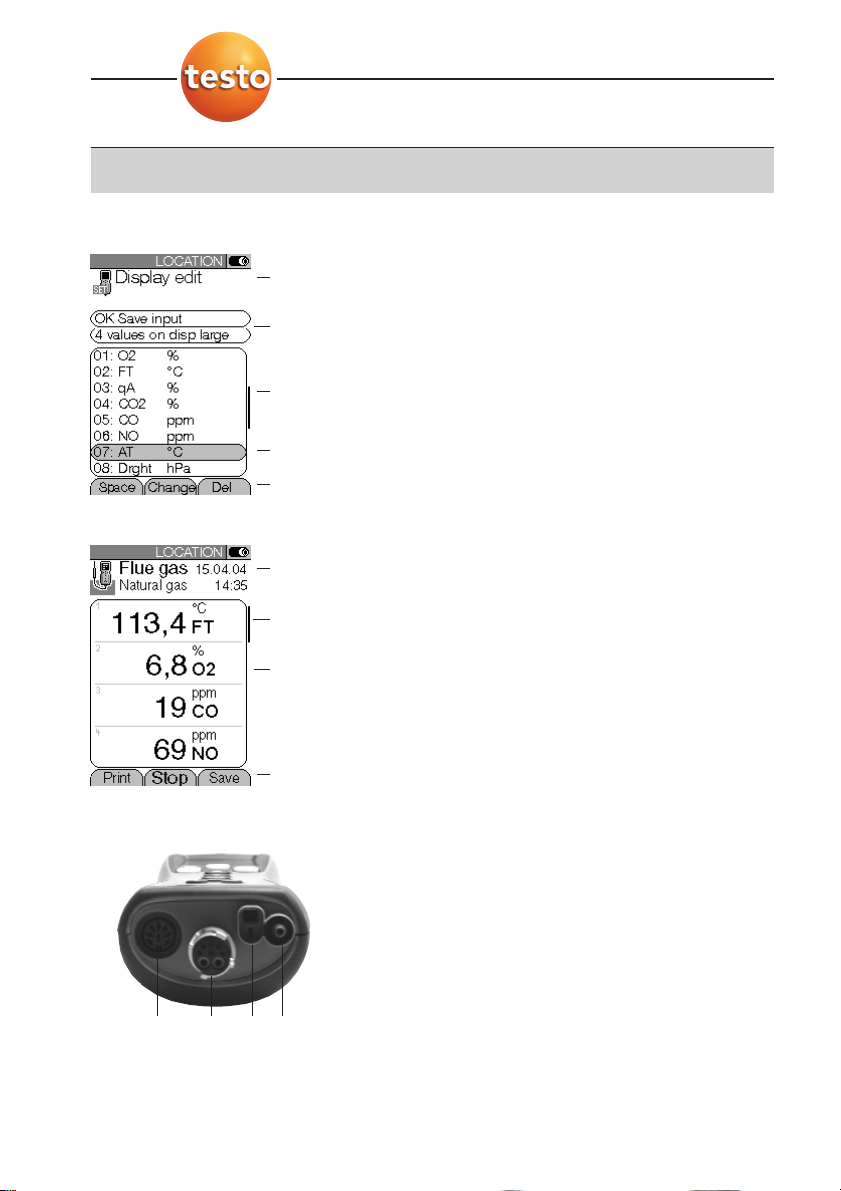
Settings view
➀ Active menu
➁ Function fields for entering commands
➂ Scroll bar
➃ Selection field for adjustable values:
The chosen value is shown with a grey
background. Unavailable values are written in grey
type.
➄ Function keys for entering commands
Measuring view
➀ Active menu, depending on the chosen function:
Additional information (e.g. activated fuel,
date and time)
➁ Scroll bar
➂ Display field for readings, parameters
➃ Function keys for entering commands
C.1.4 Device connections
➀ Probe socket
➁ Flue gas socket
➂ Mains unit socket
➃ Pressure socket
C. Product description
C.1 Measuring instrument
12
➀
➂
➃
➀
➁
➄
➃
➂
➁
➀➁ ➃➂
Page 13
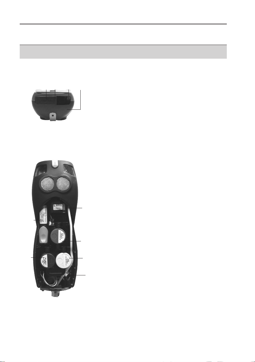
C.1.5 Interfaces
➀ USB interface:
connection to PC
➁ PS2 interface:
connection to barcode pen, adapter for automatic
furnaces
➂ Infrared interface (IrDA): connection to Ir/IrDA
printers / Pocket PC
➃ Bluetooth interface (option): connection to
Bluetooth printers/ Pocket PC
C.1.6 Components
➀ Rechargeable battery
➁ Measuring gas pump
➂ Slot for CO measuring cell
➃ Slot for O
2
measuring cell
➄ Slot for NO-, NO low measuring cell
➅ Additional filter
C. Product description
C.1 Measuring instrument
13
➄
➅
➂
➁
➀
➃
➀➁ ➂
➃
Page 14
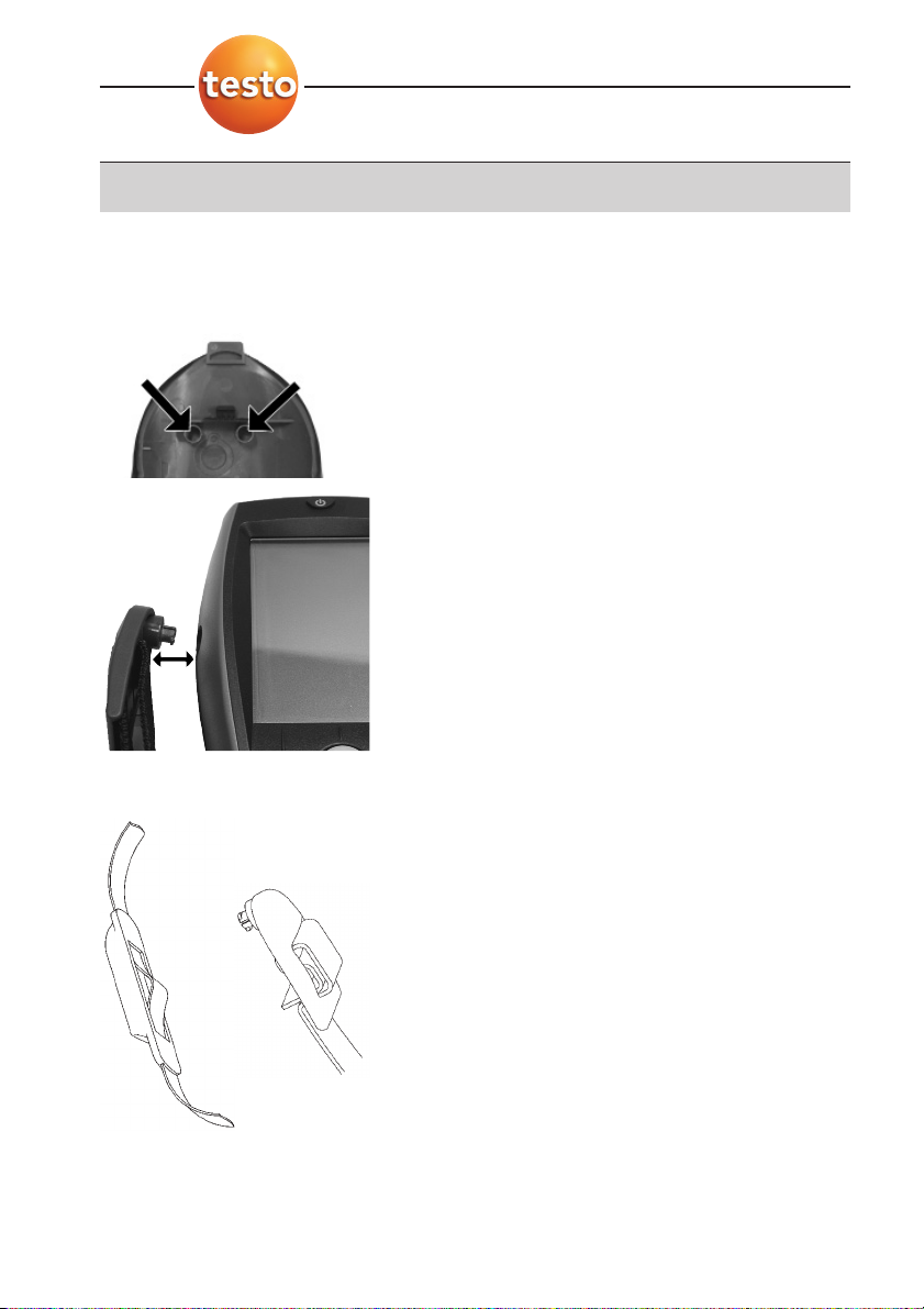
C.1.7 Carrying strap / barcode pen holder
To secure the carrying strap:
1 Remove sealing caps from the sides of the
housing.
Fix sealing caps on the inside of the service cover:
1 Place the measuring instrument on its front.
2 Pick the service cover up at the markings
(arrows) using your index finger and thumb and
press gently to release the lock.
3 Fold the service cover up and remove it.
4 Secure the sealing caps in the two holders on
the inside of the service cover (
➀).
5 Attach the service cover and engage it in place.
2 Engage the carrying strap clip in the fixing eyelets
on the side of the device. Note the guide groove.
The strap must point “down” (
➁).
To secure the barcode pen holder to the carrying strap:
1 Loosen the carrying strap at the buckle and
remove.
2
Lead carrying strap through the strap guide of the
barcode pen holder (
➂).
3 Lead carrying strap through the buckle (
➃) and
tighten.
C. Product description
C.1 Measuring instrument
14
➂
➃
➁
➀
Page 15
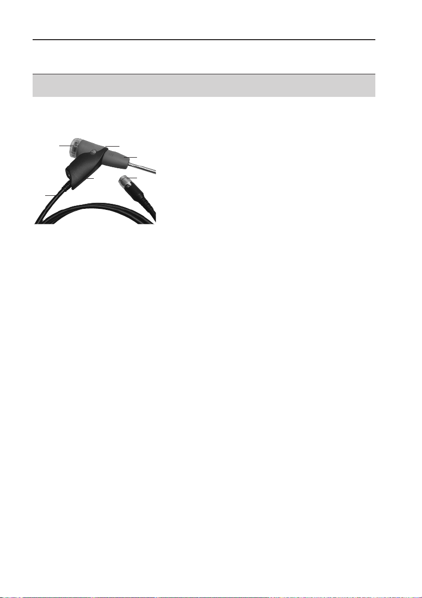
C.2 Modular flue gas probe
➀ Removable filter chamber with window and particle
filter
➁ Probe handle
➂ Connecting cable
➃ Connecting plug for measuring instrument
➄ Probe module lock release
➅ Probe module
C. Product description
C.2 Modular flue gas probe
15
➄
➅
➂
➁
➀
➃
Page 16

D. Commissioning
This chapter describes the steps required to commission the product.
Remove the protective film from the display.
The measuring instrument is supplied with a rechargeable battery already fitted.
Charge the battery up fully before using the instrument (see
Charging batteries
,
p. 18).
D. Commissioning
16
Page 17
E. Operation
This chapter describes the steps that have to be executed frequently when using the
product.
Please read this chapter carefully. The following chapters of this document will
assume you are already familiar with the content of this chapter.
E.1 Mains unit / rechargeable battery
If the mains unit is connected, the measuring instrument is automatically powered from
the unit. It is not possible to charge the battery in the instrument during operation.
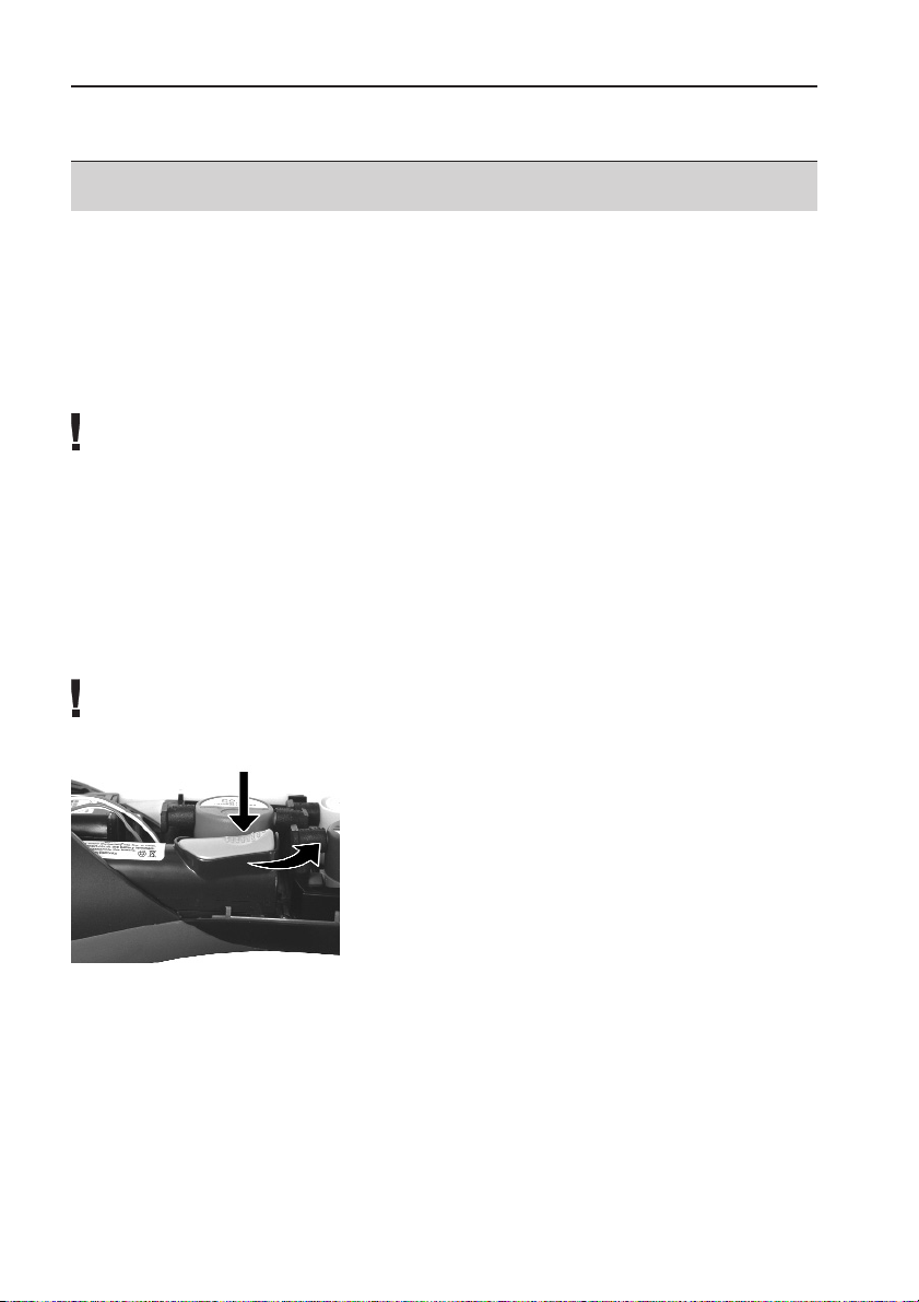
E.1.1 Changing the battery
The measuring instrument must not be connected to a mains socket via the mains
unit. The instrument must be switched off. Change the rechargeable battery within
60 minutes so that device settings (e.g. date/ time) are not lost.
1 Place the measuring instrument on its front.
2 Remove the service cover: Take hold of it at the
markings (arrows) using the index finger and
thumb, press slightly, fold up and remove.
3 Open the battery lock: Press the orange key and
push in the direction of the arrow.
4 Remove the battery and insert a new rechargeable
battery. Only use the Testo rechargeable battery
0515 0100.
5 Close battery lock: Press the orange key and push
against the direction of the arrow until the battery
engages.
6 Attach the service cover and engage it in place.
E. Operation
E.1 Mains unit/ rechargeable battery
17
Page 18

E.1.2 Charging batteries
The rechargeable battery can only be charged at an ambient temperature of ±0 to +35°C.
If the battery has discharged completely, the charging time at room temperature is
approximately 5-6h.
Charging in the measuring instrument
The instrument must be switched off.
1 Connect the plug of the mains unit to the mains unit socket on the measuring
instrument.
2 Connect the mains plug of the mains unit to a mains socket.
- The charging process will start. The charge condition will be shown on the display.
The charging process will stop automatically when the battery is fully charged.
Recharging in the charging station (0554 1087)
Refer to the documentation enclosed with the charging station.
Battery care
If possible, always discharge the battery and recharge it fully.
Do not store the battery for long periods when discharged. (The best storage
conditions are at 50-80% charge level and 10-20 °C ambient temperature; charge
fully before further use).
E.1.3 Operation with the mains unit
1 Connect the plug of the mains unit to the mains unit socket on the measuring
instrument.
2 Connect the mains plug of the mains unit to a mains socket.
- The measuring instrument is powered via the mains unit.
- If the instrument is switched off and a rechargeable battery is inserted, the charging
process will start automatically. Switching the instrument on has the effect of
stopping battery charging and the instrument is then powered via the mains unit.
E. Operation
E.1 Mains unit/ rechargeable battery
18
Page 19
E.2 Probes / Sensors
E.2.1 Connecting probes / sensors
Probe socket:
Probe detection is carried out at the socket during the initial switch on activation
process: Probes that are required must always be connected before the meas uring
instrument is switched on, or the instrument must be switched off and then on again
after a change of probe, so that the correct data can be read into the instrument.
Flue gas socket:
Probe/ sensor detection at the flue gas socket is carried out continuously. It is
possible to change the probe/ sensor even while the measuring instrument is
switched on.
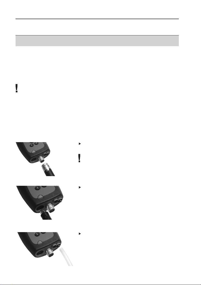
Connect flue gas probes/ gas pressure adapters/ temperature adapters
Insert the connector into the flue gas socket and
lock by turning it clockwise gently (bayonet lock).
Only one hose extension (0554 1201) should be
connected between the measuring instrument and
the flue gas probe.
Connecting other probes
Insert the connector of the probe into the probe
socket.
Connecting the pressure hose
Fit the pressure hose on the connecting nipple of
the pressure socket.
E. Operation
E.2 Probes/ Sensors
19
Page 20
E.2.2 Replacing the probe module
1 Press the key on the top of the probe handle and
remove the probe module.
2 Fit a new probe module and engage it in place.
E.3 Regular care
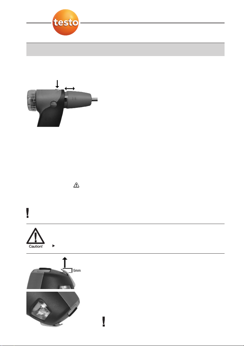
E.3.1 Condensate trap
The fill level of the condensate trap can be read from the markings on the trap.
A warning message ( red flashing light) is displayed if the level in the condensate trap
reaches 90%.
Emptying the condensate trap
The condensate consists of a weak mix of acids. Avoid contact with the skin. Make
sure that the condensate does not run over the housing.
Condensate in gas path.
Damage to measuring cells and flue gas pump.
Do not empty condensate trap while pump is operating.
1 Hold the measuring instrument so that the
condensate outlet points up.
2 Open condensate outlet in condensate trap: Pull
out approx. 5mm or until it will not go any further
(
➀).
3 Let the condensate run out into a sink (
➁).
4 Dab off drops at condensate outlet using a cloth.
5 Close the condensate outlet.
The condensate outlet must be fully closed
(marking) otherwise incorrect measurements due to
Placeholder:
Kondensatfalle_oeffnen.tif
Kondensatfalle_leeren.tif
E. Operation
E.3 Regular care
20
➁
➀
Page 21
inleaking air may result.
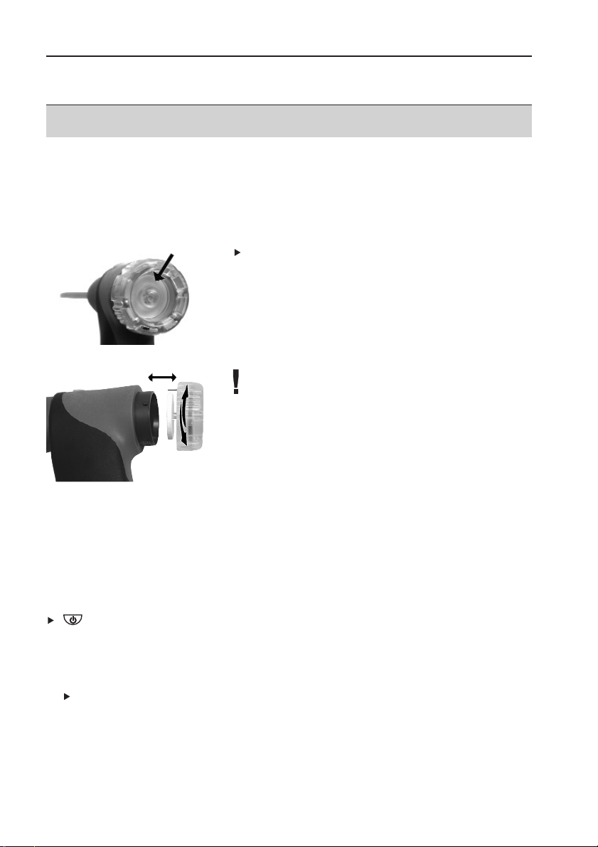
E.3.2 Checking / replacing the particle filter
Checking the particle filter:
Particle filters of the modular flue gas probe must
be checked regularly for contamination:
Check visually by looking through the window of
the filter chamber.
Replace the filter if there are signs of
contamination.
Replacing the particle filter:
Filter chamber may contain condensate.
1 Open the filter chamber: Turn gently
anticlockwise.
2 Remove the filter plate and replace it with a
new one (0554 3385).
3 Fit the filter chamber and lock it: Turn gently
clockwise.
E.4 Basic operating steps
E.4.1 Switching the measuring instrument on
.
- The start screen is displayed (for about 5 s).
- Display illumination is switched on for 10 s.
Option:
To go directly to a measurement while the start screen is being displayed, press
the function key for the desired measurement. See also
Start key configuration
,
p. 30.
- The
Measurements menu is opened.
-or-
- If another probe/ sensor is connected rather than a flue gas probe: the measuring
menu for that probe/ sensor is opened.
E. Operation
E.4 Basic operating steps
21
Page 22

-or-
- If the power supply was interrupted for a longer period: the
Date/Time menu is
opened.
-or-
- There is an instrument error:
Error diagnosis is displayed.
E.4.2 Calling up a function
Functions which cannot be selected, because the required probe/sensor is not
connected, are shown in grey type.
1 Select the function: , .
- The chosen function is shown with a grey background.
2 Confirm selection: .
- The chosen function is opened.
E.4.3 Entering values
Some functions require values (numbers, units, characters) to be entered. Depending on
the function that is chosen, the values are entered via either a list field or an input editor.
List field
1 Select the value to be changed (number, unit):
, .
2 Set the value: , .
3 Repeat steps 1 and 2 as required.
4 Confirm the input: .
5 Save the input:
OK Save input ➝ .
OK
OK
OK
E. Operation
E.4 Basic operating steps
22
Page 23

Input editor
1 Select the value (character): , , , .
2 Accept the value: .
Options:
To switch between upper-case/ lower-case
letters:
A <=> a (not always available).
To delete characters:
<=.
To position the cursor in the text: Select the text
input field: , and position the cursor:
,.
To delete characters in front of the cursor:
.
3 Repeat steps 1 and 2 as required.
4 Save the input:
OK Save input ➝ .
E.4.4 Printing data
Data are printed out via the function key . The function is only available if a
printout is possible.
If data are to be transferred to a protocol printer via the infrared or Bluetooth interface,
the printer that is to be used must be activated, see
Printer
, p. 29.
E.4.5 Saving data
Data are saved either via the function key or the function field OK Save input. The
functions are only available if saving is
possible.
See also
Memory / Location
, p. 25.
E.4.6 Confirming an error message
If an error occurs, an error message is shown in the display.
To confirm an error message: .
Errors which have occurred and have not yet been rectified are shown by a warning
symbol ( ) in the header.
Error messages which have not yet been removed can be viewed in the
Inst’ diagnosis
menu, see
Instrument diagnosis
, p. 27.
OK
Save
Print
OK
Del.
OK
E. Operation
E.4 Basic operating steps
23
Page 24

E.4.7 Scanning locations with the barcode pen
Locations marked with barcode labels can be scanned using the barcode pen
(0554 0461).
1 Connect the connector of the barcode pen to the PS2 interface of the measuring
instrument.
2 ➝
Memory / Location ➝ .
3 Scan the barcode: Hold the barcode pen over the white surface and then move
swiftly over the barcode label.
- If the scanned barcode is already created as a location in the measuring instrument,
this location is activated automatically.
If the scanned barcode is not yet created as a location in the instrument, a new
location is created.
See also
Memory / Location
, p. 25.
E.4.8 Switching the measuring instrument off
Unsaved readings are lost when the measuring instrument is switched off.
.
- Possibly: The pump starts and the measuring cells are rinsed until the shut-off
thresholds (O
2
>20%, other parameters <50 ppm) are reached. Rinsing lasts no
more than 3 minutes.
- The measuring instrument switches off.
OK
E. Operation
E.5 Memory/ Location
24
Page 25

E.5 Memory / Location
All readings are allocated to the location that is activated at the time and can be saved in
the
Flue gas menu. Unsaved readings are lost if the measuring instrument is switched off!
Locations can be created, edited and activated. (Measuring) protocols can be printed.
The special function
Extras memory can be used to display the available memory. All
protocols can be printed or deleted. The entire memory (locations and protocols) can
also be cleared.
Calling up the function:
➝
Memory / Location ➝ .
Creating a new location:
Locations are identified by a unique location name. Each location name can only be
allocated once.
1
New location ➝ .
2 Select
Location name ➝ .
3 Enter values ➝
OK Save input ➝ .
4 Execute steps 2 and 3 for the other criteria accordingly (only testo 330-2, -3 /
testo 330-2LL).
5
OK Go to measurement or OK TO memory / location ➝ .
Ordering a list (testo 330-2, -3):
1
Locations list ➝ .
2 Select the order criterion: , (only testo 330-2, -3 / testo 330-2 LL) or
(only testo 330-2, -3 / testo 330-2LL).
Restoring a list (testo 330-2, -3):
1 Order the list in the sequence in which the locations were created:
Restore list ➝ .
Activating a location:
Select the location ➝ .
- The location is activated and the
Measurements menu is opened.
OK
OK
Addr’
Locat Name
OK
OK
OK
change
OK
OK
E. Operation
E.5 Memory/ Location
25
Page 26

Printing / displaying protocols:
If automatic furnace data are stored with a measurement protocol the following symbol
is displayed next to the protocol name: . The data are printed with the protocol
printout.
1 Select the location ➝ .
Options:
To print all data of the chosen location:
Print all ➝ .
To delete all data of the chosen location:
Delete all ➝ .
2 To print a single data: Select the protocol ➝ .
-or-
2 To display saved readings of a measurement: Select the protocol ➝ .
Options:
To print the protocol: .
To delete the protocol: .
Editing the location:
1 Select the location ➝ .
Options:
To delete the location: .
To change the location: .
Special function Extras memory
Calling up a function:
➝
Memory / Location ➝ .
- The available memory is displayed.
Options:
Print all data ➝ .
Delete all data ➝ .
Delete memory ➝ .
OK
OK
OK
Extra
Change
Del
Edit
Del
Print
Value
Print
OK
OK
Protoc.
E. Operation
E.5 Memory/ Location
26
Page 27

E.6 Instrument diagnosis
Important operating values and device data are displayed. A gas path check
(testo 330-2, -3 / testo 330-2LL) can be carried out. The status of the measuring cells
and device errors which have not yet been rectified can be viewed.
Calling up the function:
➝
Inst’ diagnosis ➝ .
-or-
.
Carrying out a gas path check (testo 330-2, -3 / testo 330-2LL)
1
Gas path check ➝ .
2 Place the black sealing cap on the tip of the flue gas probe.
- The pump flow is displayed. If the flow rate is ≤0,02l/min, the gas paths are not
leaking.
3 End the check: .
Viewing device errors:
Error diagnosis ➝ .
- Unrectified errors are displayed.
View next/ previous error: , .
Viewing sensor diagnosis:
1 Sensor check ➝ .
- Possibly: Gas zeroing (30 s).
2 Select measuring cell: , .
- The status of the measuring cell is displayed.
OK
OK
OK
OK
OK
F. Configuration
E.6 Instrument diagnosis
27
Page 28

F. Configuration
This chapter describes the possible steps for adapting the product to the particular
measurement task or the requirements of the user.
Familiarity with the contents of the chapter
Operation
(see p. 17)
is assumed.
F.1 Instrument settings
F.1.1 Display edit
The parameters/ units and the display representation (number of readings displayed per
display page) can be set.
Available parameters and units:
Display Parameter Units
FT Flue gas temperature °C, °F
CO2 Carbon dioxide %
qA Flue gas loss %
λ Air ratio -
O2 Oxygen %
CO Carbon monoxide ppm, %,
mgm
3
,
g/GJ,
mgKW
uCO Carbon monoxide undiluted ppm
η Efficiency %
NO Nitrogen monoxide ppm, %,
mgm
3
,
g/GJ,
mgKW
NOx Nitrogen oxide ppm, %,
mgm3,
g/GJ,
mgKW
AT Ambient temperature °C, °F
O2 air Oxygen addition %
Drght Flue draught mbar, hPa,
mmWS,
inW
Display Parameter Units
T1 Temperature 1 (flue gas socket) °C, °F
T2 Temperature 2 (probe socket) °C, °F
ΔT Differential temperature T1 -T2 °C, °F
Itemp Instrument temperature °C, °F
DP Flue gas dew point temperature °C, °F
ΔP Differential pressure mbar, hPa,
mmW, inW
Gasfl Gas flow rate m3/h, l/h
GasP Gas burner output kW
OilFl Oil flow rate kg/h
Oil p Oil pressure bar
OilP Oil burner output kW
CO2 Carbon dioxide %
amCO2 Ambient carbon dioxide ppm
amCO Ambient carbon monoxide ppm
Pabs Absolute pressure hPa, mbar
Pump Pump output l/m
F. Configuration
F.1 Instrument settings
28
Page 29

Calling up the function:
➝
Inst’ settings ➝➝Display edit ➝ .
Setting the display representation:
Select 4 values on disp large or 8 values on disp small ➝ .
Changing parameters and units:
1 Select the display position.
Options:
To insert a line: .
To delete a parameter: .
2 ➝ Select parameter ➝➝Select unit ➝ .
Saving settings:
OK Save input ➝ .
F.1.2 Printer
The headers (lines 1-3) and the footer for the printout can be set. The printer that is used
can be activated.
Calling up the function:
➝
Inst’ settings ➝➝Printer ➝ .
Setting the printed text:
1
Print text ➝ .
2 Select
Line 1, Line 2, Line 3 or Footnote ➝ .
3 Enter values ➝
OK Save input ➝ .
4 Execute steps 2 and 3 for the other lines in the same way.
5
OK Save input ➝ .
Printer selection:
Before selecting the printer, the interface which shall be used must be activated, see
Communication
, p. 31. Only printers which support the activated interface can be
selected.
Select Printer ➝➝Select printer ➝ .
OK OK
OK
OK
change
OK
OK OK
OK
Change OK OK
Del
Space
OK
OK OK
F. Configuration
F.1 Instrument settings
29
Page 30

F.1.3 Alarm limits
A limit value can be set for ambient CO probes, leak detection probes and CO2probes.
A visual and optical alarm is triggered if a limit value is exceeded.
Calling up the function:
➝
Inst’ settings ➝➝Alarm limits ➝ .
Setting the alarm thresholds/ alarm signal:
Optional:
To reset all values to default values:
Default values ➝ .
1 Select the parameter.
Optional:
To reset the alarm threshold of the chosen parameter to the default value:
.
2 ➝ Set the values ➝ .
3 Repeat steps 1 and 2 for the other parameters/ the alarm signal as required.
Saving settings:
OK Save input ➝ .
F.1.4 Start Keys edit
How the function keys are configured depends on the chosen function. Only the
function keys in the start screen (shown when the measuring instrument is switched on)
can be assigned any function from the
Measurements menu.
The function keys are only active if the required probes are connected.
Calling up the function:
➝
Inst’ settings ➝➝Start Keys edit ➝ .
Assigning a function to the start keys:
1 Select function ➝ Press the function key that is to be assigned the chosen function.
2 Repeat step 1 for the other function keys as required.
Saving settings:
OK Save input ➝ .
OK
OK OK
OK
Change OK
Deflt
OK
OK OK
F. Configuration
F.1 Instrument settings
30
Page 31

F.1.5 t315-3 Prompt
Ambient CO/CO2 values measured with the testo 315-3 can be adopted by the
testo 330. Data is transferred via Bluetooth
®
or via the IrDA interface. For data transfer
via Bluetooth
®
, the testo 315-3 and the testo 330-2 must have this option, otherwise
data is transferred via the IrDA interface.
Preconditions for data transfer
· A measurement was carried out with the testo 315-3.
· Data transfer at the testo 315-3 has been enabled.
· No ambient CO or CO2 probe must be connected.
Call up function:
➝
Inst. settings ➝➝t315-3 connect ➝ .
Switch t315-3 prompt on/off:
1 ➝ Set values ➝ .
2
OK Save input ➝ .
- When the function is enabled, the prompt to transfer the data is executed
automatically after a flue gas measurement has been carried out.
F.1.6 Communication
Select interface IrDa/Bluetooth.
Calling up the function:
➝
Inst’ settings ➝➝Communication ➝
Set IrDa/Bluetooth:
Select
IrDA oder Bluetooth ➝ .
OK
OKchnage
OKOK
OK
OK OK
F. Configuration
F.1 Instrument settings
31
Page 32

F.1.7 Date / Time
The date and the time can be set.
Calling up the function:
➝
Inst’ settings ➝➝Date/Time ➝
Setting the date/ time:
Select Time or Date ➝➝Set the values ➝ .
Saving settings:
OK Save input ➝ .
F.1.8 Language
The menu language can be set.
Calling up the function:
➝
Inst’ settings ➝➝Language ➝ .
-or-
➝ Geräteeinst. ➝➝Sprache ➝ .
Setting the language:
Select Deutsch or Englisch ➝ .
-or-
Select
German or English ➝ .
OK
OK
OK OK
OK OK
OK
Change OK
OK OK
F. Configuration
F.1 Instrument settings
32
Page 33

F.2 Sensor settings
NO2addition and shut-off thresholds for protecting the measuring cells can be set.
Recalibration can be carried out (a calibration adapter is required: 0554 1205).
Calling up the function:
➝
Sensor settings ➝ .
Setting the NO
2
addition:
NO2 addition ➝➝Set the value ➝ .
O
2
reference:
The O
2
reference value is set to 21.00%. It cannot be changed.
Setting sensor protection:
Protection limits can be set to protect the measuring cells against overload. The sensor
protection is activated if the threshold is exceeded:
· testo 330-1 / testo 330-1LL: Switch-off
· testo 330-2, -3 / testo 330-2LL: Dilution, if exceeded again: Switch-off
If the threshold is set to 0ppm, the sensor protection is deactivated.
1
Sensor protection ➝ .
2 Select the parameter.
3 ➝ Set the values ➝ .
4 Repeat steps 2 and 3 for the other parameters in the same way.
Saving settings:
OK Save input ➝ .
Recalibration:
CO and NO measuring cells can be recalibrated. A calibration adapter (0554 1205) must
be connected.
If obviously unrealistic readings are displayed, the measuring cells should be checked
and recalibrated as required.
Have the check/ recalibration carried out by a Testo qualified service centre.
Dangerous gases
Danger of poisoning!
Observe safety regulations/ accident prevention regulations when
handling test gases.
Use test gases in well ventilated rooms only.
OK
Change OK
OK
Change OK
OK
F. Configuration
F2. Sensor settings
33
Page 34

Recalibration with low gas concentrations can lead to fluctuations in accuracy in the
upper measuring ranges.
1 Connect the calibration adapter to the flue gas socket.
2
Recalibration ➝ .
- Gas zeroing (30 s).
3 Select the parameter ➝➝Enter the test gas concentration (required value).
4 Attach the connecting cable of the test gas bottle to the calibration adapter.
5 Charge the measuring cell with test gas.
6 Start calibration: .
7 Accept the actual value as soon as the required value is stable: .
F.3 Fuels
The fuel can be chosen. The fuel-specific coefficients can be set.
Calling up the function:
➝
Fuels ➝ .
Activating fuel:
Select the fuel .
Setting coefficients:
1 .
Optional:
To reset all coefficients to default values:
Default values ➝ .
2 Select the coefficients.
Optional:
To reset the chosen coefficients to default values: .
3 ➝ Set the values ➝ .
4 OK Save input Ý .
OK
Change OK
Deflt
OK
Coeff
OK
OK
OK
Start
Change
OK
F. Configuration
F.3 Fuels
34
Page 35

G. Measuring
This chapter describes the measuring tasks that can be carried out with the product.
Familiarity with the contents of the chapter
Operation
(see p. 17) is assumed.
G.1 Preparing measurements
G.1.1 Zeroing phases
Measuring the combustion air temperature
If no combustion air temperature probe is connected, the temperature measured by the
thermocouple of the flue gas probe during the zeroing phase is used as the combustion
air temperature. All dependent parameters are calculated by this value. This method of
measuring combustion air temperature is sufficient for systems dependent on ambient
air. However, the flue gas probe must be near the intake duct of the burner during the
zeroing phase.
If a combustion air temperature probe is connected, the combustion air temperature is
measured continuously via this probe.
Gas zeroing
The first time a gas measuring function is called up after the instrument has been
switched on, the measuring cells are zeroed.
testo 330-1, -3 / testo 330-1LL: The flue gas probe must be in the open air during
the zeroing phase!
The “Gas zeroing, probe in flue (0440 3331)” option is available as an option for the
testo 330-3.
testo 330-2 / testo 330-2LL: The flue gas probe can be in the flue pipe even during
the zeroing phase, if a separate AT probe is attached.
Draught / pressure zeroing
The pressure sensors are zeroed when a pressure measuring function is called up.
testo 330-1, -2 / testo 330-1LL: The flue gas probe must be in the open air during
the zeroing phase/ the instrument must not be pressurised during zeroing! The
“Draught zeroing, probe in flue (0440 3330)” option is available as an option for the
testo 330-2.
testo 330-3 / testo 330-2LL: The flue gas probe can be in the flue pipe even during
the zeroing phase, if a separate AT probe is attached.
G. Measuring
G.1 Preparing measurements
35
Page 36

G.1.2 Using the modular flue gas probe
Checking the thermocouple
The thermocouple of the flue gas probe must not lie
against the probe cage.
Check before use. Bend the thermocouple back if
necessary.
Aligning the flue gas probe
The flue gas must be able to flow freely past the
thermocouple.
Align the probe by turning it as required.
The tip of the probe must be in the centre of the flue
gas flow.
Align the flue gas probe so that the tip is in the
centre of the flow (area of the highest flue gas
temperature).
G.1.3 Configuring the reading display
Only those parameters and units which are activated in the reading display appear in the
reading display, the saved measurement protocols and the protocol printouts.
Before beginning measurements, configure the reading display so that the required
parameters and units are activated, see
Display edit
, p. 28.
G.1.4 Set memory/location
Before carrying out measurements, the measurement location and the fuel must be
correctly selected siehe
Memory/Location, p. 25
and
Fuels, p.33.
RGS
G. Measuring
G.1 Preparing measurements
36
Page 37

G.2 Measurements
G.2.1 Flue gas
The Flue gas menu is the main measuring menu in which - in addition to the readings
measured with this function - the readings of all measurements carried out are displayed
(if selected in the
Display edit menu). All readings can also be saved or printed out from
this menu.
The
Flue gas menu can always be selected, regardless of which probes are connected.
The measurement values from the functions Draught, O2 air, Differencial temp.,
Differencial press and Smoke No./HCT are transferred to the the central measurement
menu Flue gas and must therefore be carried out before the flue gas measurement.
To achieve usable measurement results, the measurement period of a flue gas
measurement should be approx. 3 min and the measuring instrument should display
stable measured values.
Calling up the function:
➝
Measurements ➝➝Flue gas ➝ .
- Possibly: Gas zeroing (30 s).
If no fuel has yet been selected:
Select the fuel ➝ .
Measuring:
1 Start measuring: .
Reading CO undiluted:
If a separate measurement of CO undiluted has not yet been carried out, this value is
calculated using the readings of the flue gas probe and is updated continuously.
If CO undiluted has already been measured separately, the value obtained is
adopted.
- The readings are displayed.
2 Stop measuring: .
- If the function t315-3 connect is enabled: the message Upload data from t315-3
appears.
Confirm transfer of data with Yes.
Stop
Start
OK
OK OK
G. Measuring
G.2 Measurements
37
Page 38

Options:
To print readings: .
To save readings: .
- The readings from the flue gas measurement, as well as any readings taken over
into the menu
Flue Gas from other measurement functions are stored and/or
printed in a measurement protocol (automatic furnace data are not printed).
G.2.2 Draught
A flue gas probe must be connected.
The pressure socket of the instrument must be free (i.e. unpressurised, not closed).
Do not measure for longer than 5 min, as the drift of the pressure sensor means that
the readings could be outside the tolerance limits.
Calling up the function:
➝
Measurements ➝➝Draught ➝ .
Measuring:
1 Start measuring: .
- Draught zeroing (5 s).
2 Position the flue gas probe in the hot spot (area of the highest flue gas temperature).
The display showing the maximum measured flue gas temperature (FT) helps when
positioning the probe.
- The reading is displayed.
3 Stop measuring .
- The reading is recorded.
Optional:
To print the reading: .
4 Copy the reading to the
Flue gas menu: .
- The
Measurements menu is opened.
G.2.3 Fine pressure probe (accessory)
The following measurements can be carried out using the fine pressure probe:
· E-draught
· E-Delta-P
·See also instruction manual
Fine pressure probe.
OK
Print
Stop
Start
OK OK
Save
Print
G. Measuring
G.2 Measurements
38
Page 39

G.2.4 BImSchV (testo 330-3 / testo 330-2LL)
Two different prescribed measurement sequences can be performed in the BImSchV
menu: They are the BImSchV measurement sequence and the qA mean value
measurement sequence.
CO measurement can then be switched off.
In the qA mean value sequence, 3 successive flue gas loss measurements are taken
and the mean value is calculated from them.
In the BImSchV sequence, a draught measurement is performed first, then a flue gas
measurement. Regardless of the device settings, 8 readings are shown per display page
in a fixed order.
The readings are recorded in the
BImSchV menu and are not copied to the Flue gas menu!
A flue gas probe and a combustion air temperature probe must be connected.
Calling up the function:
➝
Measurements ➝➝BImSchV ➝ .
- Possibly: Gas zeroing (30 s).
If no fuel has yet been selected:
Select the fuel ➝ .
Activating/deactivating the CO measurement and Hot spot search:
1 Select
CO measurement ON or CO measurement OFF.
2 Position the flue gas probe in the hot spot (area of the highest flue gas temperature).
The display showing the current and maximum measured flue gas temperature (FT)
helps when positioning the probe.
Optional:
To reset the temperature value
max FT: .
qA mean value measurement sequence:
3 Start the measurement sequence: .
- The
qA menu is opened.
4 Start qA value measuring: .
- The three qA values are measured one after the other (25s respectively).
- The mean value of the three qA measurements is shown.
5 Copy the readings to the
BimSchV menu: .
- The
BImSchV menu is opened.
Options:
OK
Start
qA
Reset
OK
OK OK
G. Measuring
G.2 Measurements
39
Page 40

To print readings: .
To save readings: .
Start flue gas measurement (BImSchV measurement sequence): continue with the
BImSchV sequence, Step 4
, on this page.
BImSchV measurement sequence:
3 Start the measurement sequence: .
- The
BImSchV menu is opened.
4 Start flue gas measurement: .
- The readings are displayed.
5 Stop flue gas measurement: .
- The
Draught menu is opened.
6 Start draught measurement: .
- Draught zeroing (5 s).
- The reading is displayed.
7 Stop measurement .
- The reading is recorded.
8 Copy the reading to the
BImSchV menu: .
- The reading is copied to the BImSchV menu.
- The
BImSchV menu is opened.
Options:
To print readings: .
To save readings: .
Save
Print
OK
Stop
Start
Stop
Start
BImS.
Save
Print
G. Measuring
G.2 Measurements
40
Page 41

G.2.5 Solid fuel measurement (testo 330-2)
The solid fuel measurement program is only available with instruments that come with
the CO sensor (not COlow).
The function is only available if the activated fuel is solid fuel and the solid fuel
measurement adapter has been connected.
Calling up the function:
➝
Measurements ➝➝Flg. solid fuel ➝ .
Activating fuel:
Select the fuel ➝ .
Edit the measurement period:
Set measurement period: , ➝ ➝ , , , . ➝
Performing the measurement:
1 Position the flue gas probe in the hot spot (area of the highest flue gas temperature).
The display showing the maximum measured flue gas temperature (FT) helps when
positioning the probe.
2 Start measurement: .
- Adaptation time (60s).
- Measurement period (depending on setting)
3 Start draught measurement: .
- Draught zeroing (5s).
- The reading is displayed.
4 End measurement: .
- The reading is accepted.
Option:
To print the reading: .
To save the reading: .
speichk
druck
Stop
Start
Start
ändern OK
OK
OK OK
G. Measuring
G.2 Measurements
41
Page 42

G.2.6 CO undiluted
A multi-hole probe (0554 5762) must be connected.
Calling up the function:
➝
Measurements ➝➝CO undiluted ➝ .
Measuring:
1 Start measurement: .
- Possibly: Gas zeroing (30 s).
- The reading is displayed.
2 Stop measurement: .
- The reading is recorded.
Options:
To print the reading: .
3 Copy the reading to the
Flue gas menu: .
- The
Measurements menu is opened.
G.2.7 Smoke No./ HCT
Calling up the function:
➝
Measurements ➝➝Smoke No./ HCT ➝ .
Recording smoke tester no./ smoke numbers/ oil derivative with the smoke pump
and manual input:
The function is only available if the chosen fuel is an oil.
1
Sm. tester no. ➝➝Enter pump number ➝ .
2
Smoke# 1 ➝➝Enter the value ➝ .
3 Repeat step 2 for the other smoke numbers and oil derivative as required.
Recording smoke tester no./ smoke numbers/ oil derivative with the smoke tester
testo 308 and wireless transfer:
- testo 308 must be in data transfer mode ( lights up).
1 Press function key .
- The values recorded by the smoke tester are transferred.
2 Once all values have been transferred, select function key .
OK
t308
Change OK
Change OK
OK OK
OK
Print
Stop
Start
OK OK
G. Measuring
G.2 Measurements
42
Page 43

Entering the heat carrier temperature:
Heat carrier ➝➝Enter the value ➝ .
Copy the values to the Flue gas menu:
The smoke number/HCT-values are not displayed in the menu
Flue gas. They can,
however, be printed or stored in a measurement protocol, together with the
measurement values of a flue gas measurement. In the menu
Memory / Location, the
smoke count/WTT values can be displayed in the measurement program, printed or
transferred to a Pocket PC/PC.
OK Copy readings ➝ .
- The
Measurements menu is opened.
G.2.8 Differential pressure
The gas pressure set (0554 1203) must be connected.
Dangerous mixture of gases
Danger of explosion!
Make sure there are no leaks between the sampling point and the
measuring instrument.
Do not smoke or use naked flames during measurement.
Do not measure for longer than 5 min, as the drift of the pressure sensor means that
the readings could be outside the tolerance limits.
Calling up the function:
➝
Measurements ➝➝Differential press. ➝ .
Measuring:
1 Start measurement: .
- Pressure zeroing (3 s).
Pressurise the connecting lines.
- The reading is displayed.
2 Stop measurement: .
- The reading is recorded.
Options:
To print the reading: .
Print
Stop
Start
OK OK
OK
Change OK
G. Measuring
G.2 Measurements
43
Page 44

3 Copy the reading to the
Flue gas menu: .
- The
Measurements menu is opened.
G.2.9 Differential temperature
The difference temperature set (0554 1204) must be connected.
Calling up the function:
➝
Measurements ➝➝Differential temp. ➝ .
Measuring:
1 Start measurement: .
- The readings and the calculated temperature difference (T1 - T2) are displayed.
2 Stop measurement: .
- The readings are recorded.
Options:
To print readings: .
3 Copy the readings to the
Flue gas menu: .
- The
Measurements menu is opened.
G.2.10 O2 air
An O2dual wall clearance probe (0632 1260) must be connected.
Calling up the function:
➝
Measurements ➝➝O2 air ➝ .
Measuring:
1 Start measurement: .
- Possibly: Gas zeroing (30 s).
- The reading is displayed.
2 Stop measurement: .
- The reading is recorded.
Optional:
To print the reading: .
3 Copy the reading to the
Flue gas menu: .
- The
Measurements menu is opened.
OK
Print
Stop
Start
OK OK
OK
Print
Stop
Start
OK OK
OK
G. Measuring
G.2 Measurements
44
Page 45

G.2.11 Gas flow rate
The Gas flow rate function is only available if the activated fuel is a gas.
Calling up the function:
➝
Measurements ➝➝Gas flow rate ➝ .
Measuring:
1 Enter the duration of measurement:
Sample time ➝➝Enter the value (18, 36 or
180
s) ➝ .
2 Start measuring: . Observe the counter reading of the gas meter.
- The remaining measurement period is displayed.
- When the measurement period has lapsed, a long beep is emitted. The last 5s are
indicated by a short beep.
3 Enter the flow rate:
Flow rate ➝ Enter the value ➝ .
- The calculated gas burner output is displayed.
4 Copy the values to the
Flue gas menu: OK Copy readings ➝ .
- The
Measurements menu is opened.
G.2.12 Oil flow rate
The Oil flow rate function is only available if the activated fuel is an oil.
Calling up the function:
➝
Measurements ➝➝Oil flow rate ➝ .
Measuring:
1 Enter the flow rate:
Flow rate ➝➝Enter the value ➝ .
2 Enter the oil pressure:
Oil pressure ➝➝Enter the value ➝ .
- The calculated oil burner output is displayed.
3 Copy the values to the
Flue gas menu: OK Copy readings ➝ .
- The
Measurements menu is opened.
OK
Change OK
Change OK
OK OK
OK
OK
Start
OK
Change
OK OK
G. Measuring
G.2 Measurements
45
Page 46

G.2.13 Leak detection
Gas is detected during leak detection; the gases are not measured.
A gas leak probe (0632 3330) must be connected.
Please refer to the documentation enclosed with the gas leak probe.
Calling up the function:
➝
Measurements ➝➝Leak detection ➝ .
Measuring:
Carry out the setting for the gas to be detected according to the instructions found in
the documentation for the gas leak probe.
- The gas concentration is shown in a graph (trend display).
- An alarm message is given if the alarm threshold is exceeded.
Set alarm threshold: see
Alarm limits
, p. 30.
G.2.14 Ambient CO
An ambient CO probe (recommended) or a flue gas probe must be connected.
Cigarette smoke influences the measurement by more than 50 ppm. The breath of a
smoker influences the measurement by about 5 ppm.
When using an ambient CO probe, note that:
The direction of flow of the gas has an effect on the accuracy of measurement.
Frontal flow onto the probe leads to higher readings. The best measurement results
are achieved when the probe is moved gently backwards and forwards.
When using the ambient CO probe 0632 1247, note that:
The sealing cap must remain closed during the zeroing phase.
Only open the sealing cap for the period of measurement.
When using ambient CO probe 0632 3331 or a flue gas probe, note that:
The probe must be located in fresh air (CO free) during the zeroing phase.
Calling up the function:
➝
Measurements ➝➝Ambient CO ➝ .
Measuring:
1 Start measurement: .
- If measuring using a flue gas probe or the ambient CO probe 0632 1247 possibly:
gas zeroing (30 s).
Start
OK OK
OK OK
G. Measuring
G.2 Measurements
46
Page 47

- Measuring starts and the reading is displayed as a number and graphically.
- An alarm message is given if the alarm threshold is exceeded.
Set alarm threshold: see
Alarm limits
, p. 30.
2 Stop measurement: .
- The reading is recorded.
Options:
To print the reading: .
3 Copy the reading to the
Flue gas menu: .
- The
Measurements menu is opened.
G.2.15 Ambient CO2
An ambient CO2probe (0632 1240) must be connected.
In order to obtain correct readings, it is imperative to enter the prevailing absolute
pressure.
Calling up the function:
➝ Measurements ➝➝Ambient CO2 ➝ .
Enter absolute pressure directly:
Absolute ➝➝Set the value ➝ .
-or-
Enter absolute pressure via barometric pressure and height:
1
From height ➝➝Barometric ➝➝Set the value ➝ .
2
Altitude ➝➝Set the value ➝ .
3
OK Save input ➝ .
Measuring:
1 Start measuring: .
- Possibly: warming-up phase (up to 30s).
- The reading is displayed.
- An alarm message is given if the alarm threshold is exceeded.
Set alarm threshold: see
Alarm limits
, p. 30.
2 Stop measuring: .
- The reading is recorded.
Optional:
To print the reading: .
Print
Stop
Start
OK
Change OK
OK Change OK
OK OK
OK OK
OK
Print
Stop
G. Measuring
G.2 Measurements
47
Page 48

3 Copy the reading to the
Flue gas menu: .
- The
Measurements menu is opened.
G.2.16 Burner control
With the help of the readout adapter for automatic furnaces (0554 1206), status data
and malfunction reports can be read out from compatible automatic furnaces, see also
documentation for readout adapter. The range of data which can be read out is
dependent on the automatic furnace type.
Calling up the function:
1 Connect readout adapter to the instrument (PS2 interface) and the automatic furnace
(use adapter ring if necessary).
2 ➝
Measurements ➝ ➝ Burner Control.
Option:
Display type and version of the adapter: .
3 .
- The data are read from the automatic furnace. An update of the data takes place
every 30s at the latest, this is dependent on the automatic furnace.
Reading out current status data:
The current data are displayed when a connection to the automatic furnace exists. The
following data are displayed with the help of symbols:
Component Status ON Status OFF Component Status ON Status OFF
Air controller Flame Symbol
not displayed
Motor Ignition
Valve1 Oil prewarmer
Valve 2
Printing data:
.
Display identification data:
Info ➝ .
Display failure statistic:
OK
Print
OK
Adapt.
OK
OK
G. Measuring
G.2 Measurements
48
Page 49

Failure statistic ➝ .
Reading out failure store:
Automatic furnaces are equipped with circular buffer memories, i.e. failure reports are
overwritten when the failure store is full.. The last failure occurring is at position 1 in the
failure list.
.
Option:
Scroll through failure list: , .
Taking readings over into the menu Flue Gas:
The readings are not presented in the display, in the menu
Flue Gas they can be stored
with the readings from a flue gas measurement, stored in a measurement protocol or
transferred to a pocket PC/PC.
For taking data over into the menu
Flue Gas the function fields Info and Failure statistic
must not be active (grey background).
.
- The Menu Measurements is opened.
OK
Failure
OK
G. Measuring
G.2 Measurements
49
Page 50

H. Transferring data
H.1 Protocol printer
If data are to be transferred to a Testo protocol printer via the infrared or Bluetooth
interface, the printer that is to be used must be activated, see
Printer
, p. 29.
Data are printed out via the function key . The function is only available if a
printout is possible.
H.2 PC / Pocket PC
Data can be transferred to a PC via USB, IrDA oder Bluetooth®.
Data can be transferred to a Pocket PC via infrared or Bluetooth
®
.
You must also refer to the documentation that comes with the software.
Print
H. Transferring data
50
Page 51

I. Care and maintenance
This chapter describes the steps and action required in order to keep the product
functioning properly.
See also
Regular care
, p. 20.
I.1 Cleaning the measuring instrument
If the housing of the instrument is dirty, clean it with a damp cloth. Do not use any
aggressive cleaning agents or solvents! Weak household cleaning agents and soap
water may be used.
I.2 Replacing measuring cells
A slot bridge (0192 1552) must be inserted in slots which do not have a measuring cell.
Used measuring cells must be disposed of as special waste!
The instrument must be switched off.
1 Place the measuring instrument on its front.
2 Remove the service cover: Take hold of it at the markings (arrows) using the index
finger and thumb, press slightly, fold up and remove.
3 Pull hose connections from the fault measuring cell/ bridge.
4 Remove the faulty measuring cell/ bridge from the slot.
Remove short-circuit brackets/ additional boards
from the new measuring cells just prior to insertion.
Do not leave measuring cells for longer than 15
minutes without short-circuit brackets/ additional
boards.
CO measuring cell: Remove the shorting jumper
(2).
NO / NO
low
measuring cell:
Remove the auxiliary circuit board (1).
Placeholder:
Zellenwechsel.tif
I. Care and maintenance
51
Page 52

5 Insert a new measuring cell/ bridge in the slot.
6 Attach hose connections to the measuring cell/ bridge.
7 Attach the service cover and engage it in place.
After replacing an O
2
measuring cell, wait 60 minutes before using the instrument
again.
The corresponding parameter and unit have to be activated when measuring cells are
upgraded. See
Display edit
, p.28.
I.3 Recalibrating measuring cells
See
Sensor settings
, p. 32.
I.4 Replacing additional filter
The additional filter provides added protection should problems occur with the particle
filter in the flue gas probe. The additional filter is very rarely contaminated if the
measuring instrument is used normally.
Check the additional filter (visually) for contamination from time to time and replace it
if necessary.
1 Place the measuring instrument on its front.
2 Remove the service cover: Take hold of it at the
markings (arrows) using the index finger and
thumb, press slightly, fold up and remove.
3 Release the additional filter from the hose
connections.
4 Fit a new filter (0133 0010) on the hose
connections.
5 Attach the service cover and engage it in place.
I. Care and maintenance
52
Page 53

I.5 Cleaning the modular flue gas probe
Disconnect the flue gas probe from the measuring
instrument prior to cleaning.
1 Release the probe catch by pressing the key on
the probe handle and remove the probe module.
2 Blow compressed air through the flue ducts of the
probe module and probe handle (see illustration).
Do not use a brush!
3 Fit a new probe module on the handle and engage
it in place.
I.6 Changing the thermocouple
1 Release the probe catch by pressing the key on
the probe handle and remove the probe module.
2 Remove the thermocouple plug-in head from the
socket using a screwdriver and pull the
thermocouple out of the probe shaft.
3 Keep inserting new thermocouple in the probe
shaft until the connection head clicks into place.
4 Fit a new probe module on the handle and engage
it in place.
I. Care and maintenance
53
Page 54

J. Questions and Answers
This chapter gives answers to frequently asked questions.
Question Possible causes Remedy
Measuring instrument keeps Battery spent Charge the battery or connect the
switching off by itself or mains unit (see
Operation
, p. 17).
Measuring instrument will
not switch on.
Display of the battery capacity Battery was often not fully discharged/ Discharge battery fully (until instrument
appears faulty charged. switches off by itself) and then charge
fully.
Failure report: Gas output closed. Ensure that gas output is free
Pump flow rate to high
Message: The shutdown threshold of the Remove probe from flue.
Gas cell shutdown-thres- CO sensor has been exceeded
hold has been exceeded
Failure report: · With printer 0554 0543: The wrong interface Activate correct interface
Printing not possible is activated. (see
Communication
, p. 31).
· The wrong printer is activated. Activate correct printer
(see
Printer
, p. 29).
· Printer is switched off. Switch printer on.
· Printer is out of wireless range. Place printer within wireless range.
If we were unable to answer your question. please contact your distributor or Testo
Customer Service. For contact data, see back of this document or web page
www.testo.com/service-contact
J. Questions and Answers
54
Page 55

K. Technical data
K.1 Standards and inspections
· As declared in the certificate of conformity, this product fulfils the guidelines of
2004/108/EEC.
· This product is TÜV approved to 1. BImSchV.
· This product is TÜV tested in accordance with EN50379 part 2, exception: The
parameter CO in the instrument versions testo 330-1/ testo 330-1LL are TÜV tested in
accordance with EN50379 part 3.
· For official measurements in accordance with 1. BImSchV (chimney sweeps), the
measuring instrument must be checked every six months by a technical testing body of
the Guild of Master Chimney Sweeps or another testing body recognised by the
authorities.
K. Technical data
55
Page 56

K.2 Measuring ranges and accuracies
Parameter Measuring range Accuracy Resolution t90
1
O2 0...21 Vol.% ±0.2 Vol.% 0.1 Vol.% <20s
CO 0...4,000 ppm ±20 ppm at 0...400 ppm 1 ppm <40s
(testo 330-1 / (H2 level < 10%) ±5 % of reading at 400.1...1,000 ppm
testo 330-1LL) ±10 % of reading at 1,000.1...4,000 ppm
CO, H2-comp. 0...8,000 ppm ±10 ppm or 1 ppm < 40s
(testo 330-2, -3 / ±10 % of reading
3
at 0...200 ppm
testo 330-2LL)
2
±20 ppm or
±5 % of reading
3
at 201...2,000 ppm
±10 % of reading at 2,001...8,000 ppm
only testo 330-2 LL0...30000 ppm ±100 ppm at 0...1000 ppm 1 ppm CO, H2-comp. ±10% of reading at 1001...30000 ppm
Fsolid fuel
measurement
amCO, via 0...2,000 ppm ±10 ppm at 0...100 ppm 1 ppm <35s
flue gas probe ±10 % of reading at 101...2,000 ppm
amCO, via 0...500ppm ±5ppm at 0...100ppm
4
1ppm -
0632 3331 ±5% of reading at 101...500ppm
4
NO (NOlow 0...300 ppm ±2 ppm at 0.0...40.0 ppm 0.1 ppm <30s
meas. cell) ±5 % of reading at 40.1...300.0 ppm
NO (NO meas. 0...3,000 ppm ± 5ppm at 0...100ppm 1ppm < 30s
cell) ±5% of reading at 101...2,000ppm
±10% of reading at 2001...3,000ppm
Draught
5
-9.99...40 hPa ±0.02 hPa or 0.01 hPa ±5% of reading
3
at -0.50...0.60 hPa
±0.03 hPa at 0.61...3.00 hPa
±1.5 % of reading at 3.01...40.00 hPa
ΔP 0...200 hPa ±0.5 hPa at 0.0...50.0 hPa 0.1 hPa -
±1 % of reading at 50.1...100.0 hPa
±1.5 % of reading at 100.1...200.0 hPa
1
Response time 90%; recommended minimum measurement time to ensure correct measurement values: 3 min;
2
above sensor protection limit: Resolution 500ppm (up to max. 30000ppm);3 the larger value applies;
4
at 10...30°C, outside this range additionally ±0.2% of reading/ °C ; 5with fine draught measurement option:
Measuring range 0...100.0Pa, Resolution 0.1Pa
Parameter Measuring range Accuracy Resolution t90
1
Temperature -40...1,200 °C ±0.5 °C at 0.0...100.0 °C 0.1 °C at -40...999.9 °C Depending
±0.5 % of reading in rem. range 1 °C in rem. range on probe
Efficiency 0...120 % - 0.1 % Flue gas loss -20.0...99.9 % - 0.1 % amCO2, via 0...10,000ppm ±50ppm+2% of reading at 0...5,000ppm 1ppm -
0632 1240 ±100ppm+3% of reading at 5001...10,000ppm
1
Response time 90%; recommended minimum measurement time to ensure correct measurement values: 3 min
K. Technical data
56
Page 57

K.3 Other device data
Characteristic Values
Operating temperature range -5...45 °C
Storage / transport temperature -20...50 °C
Ambient humidity 0...90% RH, not condensing
Power supply Battery block: 3.7V/ 2.4Ah
Mains unit: 6.3 V / 1.2 A
Dimensions (L x W x H) 270 x 90 x 65 mm
Weight 600g (excluding battery)
Memory testo 330-1, -2 / testo 330-1LL: 200 locations
testo 330-3 / testo 330-2LL: 400 locations
Display Monochrome, 4 grey levels, 160 x 240 pixels
Battery storage temperature: ±0...35°C
Battery life >6h (pump on, display lighting off, 20 °C ambient temperature)
Battery charge time approx. 5-6 h
Warranty testo 330-1, -2, -3: testo 330-1 LL, -2LL:
Measuring instrument: 24 months Measuring instrument: 48 Monate
Measuring cells: 24 months LL-Measuring cells 0
2
, CO: 48 Monate,
Other Measuring cells: 24 Monate
Flue gas probe: 24 months Flue gas probe: 48 Monate
Thermocouple: 12 months Thermocouple: 12 Monate
Battery: 12 months Battery: 12 Monate
Warranty conditions: see www.testo.com/warranty
Option Bluetooth
®
Typ-designation: BlueNiceCom IV
Bluetooth Qualified Product Notice: BNC4_HW2x_SW2xx
Bluetooth listing identifier: B013784
Bluetooth listing company: 10274
Option Bluetooth
®
Range <10m
Option Bluetooth
®
EU countries
Certification Belgium (BE), Bulgaria (BG), Denmark (DK), Germany (DE), Estonia (EE), Finland (FI), France (FR),
Greece (GR), Ireland (IE), Italy (IT), Latvia (LV), Lithuania (LT), Luxembourg (LU), Malta (MT),
Netherlands (NL), Austria (AT), Poland (PL), Portugal (PT), Romania (RO), Sweden (SE),
Slovakia (SK), Slovenia (SI), Spain (ES), Czech Republic (CZ), Hungary (HU), United Kingdom (GB)
and Republic of Cyprus (CY).
Other EFTA Countries
Iceland, Liechtenstein, Norway and Switzerland
Non-European countries
Colombia, Turkey, El Salvador
Information from FCC (Federal Communcations Commision)
- This instrument fulfils 15 of the FCC guideline
- Commissioning is subject to the following two conditions:
1. This instrument may not cause any dangerous interference
2. This instrument must accept any interference received, including interference which may
cause undesired operation.
Changes
The FCC requires that the user is informed that all changes and modifications to the
instrument which are not expressly approved by Testo AG, can void the right of the user to
operate the instrument.
K. Technical data
57
Page 58

. K.4 EC declaration of conformity
K. Technical data
58
Page 59

K.5 Principles of calculation
K.5.1 Fuel parameters
Fuel A2
1
B
1
CO2max O2reference
Natural gas 0,660 0,009 11,8 Vol.% 3 Vol.%
Light oil 0,680 0,007 15,4 Vol.% 3 Vol.%
LPG 0,630 0,008 13,7 Vol.% 3 Vol.%
Wood 0,765 0,000 20,3 Vol.% 13 Vol.%
Pellets 0,765 0,000 20,3 Vol.% 13 Vol.%
Briquette 0,833 0,000 18,9 Vol.% 8 Vol.%
Lignite 0,955 0,000 19,8 Vol.% 8 Vol.%
Anthracite 0,758 0,000 20,5 Vol.% 8 Vol.%
Coke oven 0,600 0,011 10,3 Vol.% 3 Vol.%
gas
Town gas 0,630 0,011 13,6 Vol.% 3 Vol.%
Test gas 0,0000 0,000 0,00 Vol.% 0 Vol.%
1
Fuel-specific factor
2
Default setting
K.5.2 Calculation formulae
Carbon dioxide: CO2 =
C02max: Maximum carbon dioxide specific to fuel
21%: Oxygen level of air
O2: Measured oxygen level in %
Flue gas loss: qA =
(
(FT-AT) x ( + B )
)
- Kk
FT: Flue gas temperature
AT: Ambient temperature
A2 / B: Fuel-specific parameters
21%: Oxygen level of air
O2: Measured oxygen level in %
Kk: Calculated value allowing for regained condensate heat if dewpoint level is not
reached (for condensing furnaces).
Efficiency: η = 100 - qA
qA
: Calculated flue gas loss
A2
21% - O2
CO
2max
x (21% - O2)
21%
K. Technical data
59
Page 60

Air ratio: λ =
C02max: Maximum carbon dioxide specific to fuel
CO2: Calculated carbon dioxide value
Nitrogen oxide: NOx = NO + (NO2add x NO)
NO
: Measured nitrogen monoxide value
NO2add: Nitrogen dioxide addition factor
Carbon monoxide
undiluted: uCO = CO x λ
CO
: Measured carbon monoxide value
λ: calculated air ratio
Flue gas dew point
temperature: FTP =
FH20: Flue gas specific water vapour level in Vol.%
PAbs: Absolute pressure in mbar/hPa
Conversion of ppm in mg/m3:
Carbon monoxide: CO [mg/m
3
] = x CO [ppm] x 1.25
21%: Oxygen level of air
O2: Measured oxygen level in %
O2ref: Fuel-specific oxygen reference value in %
Nitrogen oxide: NOx [mg/m
3
] = x NOx [ppm] x 2.05
21%: Oxygen level of air
O2: Measured oxygen level in %
O2ref: Fuel-specific oxygen reference value in %
21% - O2ref
21% - O2
21% - O2ref
21% - O2
ln (
ln (
FH20 x PAbs
610.78
FH20 x PAbs
610.78
)x 234.175
)- 17.08085
CO2max
CO2
K. Technical data
60
Page 61

L. Accessories / Spare parts
Designation Part no.
Modular flue gas probes
Modular flue gas probe 180 mm, 500 °C, thermocouple 0.5 mm, probe shaft diameter: 8 mm 0600 9760
Modular flue gas probe 300 mm, 500 °C, thermocouple 0.5 mm, probe shaft diameter: 8 mm 0600 9761
Modular flue gas probe 180 mm, 500 °C, thermocouple 0.5 mm, probe shaft diameter: 6 mm 0600 9762
Modular flue gas probe 300 mm, 500 °C, thermocouple 0.5 mm, probe shaft diameter: 6 mm 0600 9763
Probe modules/ Accessories for modular flue gas probes
Probe shaft module 180 mm, 500 °C, thermocouple 0.5 mm, probe shaft diameter: 8 mm 0554 9760
Probe shaft module 300 mm, 500 °C, thermocouple 0.5 mm, probe shaft diameter: 8 mm 0554 9761
Probe shaft module 180 mm, 500 °C, thermocouple 0.5 mm, probe shaft diameter: 6 mm 0554 9762
Probe shaft module 300 mm, 500 °C, thermocouple 0.5 mm, probe shaft diameter: 6 mm 0554 9763
Probe shaft module 300 mm, 1,000 °C, thermocouple 1.0 mm, probe shaft diameter: 6 mm 0554 8764
Probe shaft module 700 mm, 1,000 °C, thermocouple 1.0 mm, probe shaft diameter: 6 mm 0554 8765
Spare thermocouple for module 0554 9760, 0554 9762 0430 9760
Spare thermocouple for module 0554 9761, 0554 9763 0430 9761
Spare thermocouple for module 0554 8764 0430 8764
Spare thermocouple for module 0554 8765 0430 8765
Cone, 8mm, steel 0554 3330
Cone, 6mm, steel 0554 3329
Flexible probe shaft module 0554 9764
Extension for modular flue gas probe, 2.80 m 0554 1201
Particle filter, 10 pcs. 0554 3385
Temperature probes
Combustion air temperature probe, 300 mm 0600 9791
Combustion air temperature probe, 190 mm 0600 9787
Combustion air temperature probe, 60 mm 0600 9797
Pipe wrap probe 0600 4593
Surface probe (angled) 0600 0994
Other probes
O2 dual wall clearance probe 0632 1260
Gas leak probe 0632 3330
Ambient CO probe 0632 3331
Ambient CO2 probe (without connecting cable) 0632 1240
Connectiing cable for Ambient CO2 probe, 1,5m 0430 0143
Gas pressure set: Draught path adapter, silicone hose 4 mm/ 6 mm, reducing cones 0554 1203
Difference temperature set, 2 pipe contact probes, adapter 0554 1204
Readout adapter for automatic furnaces 0554 1206
L. Accessoires/ Spare parts
61
Page 62

Designation Part no.
Retrofitted measuring cells
NOlow retrofitting 0554 3931
NO retrofitting 0554 3922
Upgrade to testo 330 LL
Retrofitting of LL measurement cells, only by Testo customer service on request
Spare measuring cells
O2 measuring cell for testo 330-1, -2, -3 0390 0092
CO measuring cell for testo 330-1 0390 0115
CO measuring cell for testo 330-2, -3 (H2-compensated) 0390 0109
O2measurement cell for testo 330-1LL, -2LL 0390 0061
CO measurement cell for testo 330-1LL 0390 0118
CO measurement cell for testo 330-2LL (H2-compensated) 0390 0090
NOlow measuring cell 0390 0094
NO measuring cell 0390 0074
Cases
Service case high 0516 3331
Service case flat 0516 3330
Printers
Infrared printer 0554 0549
Bluetooth printer incl. rechargeable battery and charging adapter 0554 0543
Other accessories
Solid fuel measurement module with adapter and probe shaft with sintered filter 0600 9765
Sintered filter for solid fuel measurement probe shaft 0133 0035
Filter material for condensate trap on solid fuel measurement adapter 0133 0012
Barcode pen 0554 0461
Mains unit 0554 1086
Charger with spare battery 0554 1087
Spare battery (rechargeable) 0515 0100
Device/ PC connecting cable 0449 0047
Easyheat (PC configuration software) 0554 3332
Full version Easyheat and Easyheat mobile (PC configuration software and software for Windows Handheld PCs) 0554 1210
Upgrade Easyheat mobile (Software für Windows Handheld PCs) 0554 1211
Additional filter 0133 0010
Flue draught set 0554 3150
Fine pressure probe 0638 0330
Capillary hose set 0554 1215
L. Accessoires/ Spare parts
62
Page 63

Functional overview
The table gives an overview of the most important functions configured on the individual
instruments. Detailed information about the individual functions can be found on the
pages indicated.
testo 330 Task Call/ function see page
-1 -2 -3
-1LL -2 LL
➝ Measurements ➝➝
x x x Carry out flue gas measurement Flue gas ➝ p. 36
x x x Carry out draught measurement Draught ➝ p. 37
x Carry out flue gas measurement sequence BImSchV ➝ p. 38
BImSchV or qA mean value
x x x Carry out CO undiluted measurement CO undiluted ➝ p. 41
x x x Enter smoke no./ heat carrier temperature Smoke No. / HCT ➝ p. 41
x x x Carry out differential pressure measurement Differential press. ➝ p. 42
x x x Carry out differential temperature measurement Differential temp. ➝ p. 43
x x x Carry out O2 air supply measurement O2 air ➝ p. 43
x x x Determine gas flow rate Gas flow rate ➝ p. 44
x x x Determine oil flow rate Oil flow rate ➝ p. 44
x x x Carry out gas leak search Leak detection ➝ p. 45
x x x Carry out ambient CO measurement Ambient CO ➝ p. 45
x x x Carry out ambient CO2 measurement Ambient CO2 ➝ p. 46
x x x Read automatic furnace Burner control ➝ p. 47
➝ Memory/Location ➝➝
x x x Create new location New location ➝ p. 25
x Order location list by location name Locations list ➝ p. 25
x x Order location list by name or address Locations list ➝ or p. 25
x x x Order location list by sequence of creation Restore list ➝ p. 25
x x x Display measurements of one location Select location ➝ p. 25
x x x Print all measurements of a location Select location ➝ ➝ Print all ➝ p. 25
x x x Delete all measurements of a location Select location ➝ ➝ Delete all ➝ p. 25
x x x Show readings of selected measurements Select location ➝ ➝ Select protocol ➝ p. 25
of a location
x x x Print selected measurements of a location Select location ➝ ➝ Select protocol ➝ p. 25
➝ Memory/Location ➝➝
x x x Print all measurements in the memory Print all data ➝ p. 25
x x x Delete all measurements in the memory Delete all data ➝ p. 25
x x x Delete entire memory (measurements Delete memory ➝ p. 25
and locations)
OK
OK
OK
Extra
Print
Data
Value
Data
Data OK
Data OK
Data
OK
Name Addr’
Locat
OK
OK
OK
OK
OK
OK
OK
OK
OK
OK
OK
OK
OK
OK
OK
OK
OK
Functional overview
63
Page 64

testo 330 Task Call/ function see page
-1 -2 -3
-1LL -2 LL
➝ Instr’ settings ➝➝
x x x Set reading display Display edit ➝ p. 28
x x x Select printer, set printing text Printer ➝ p. 29
x x x Set alarm thresholds Alarm limits ➝ p. 30
x x x Set start screen function key assignment Start Keys edit ➝ p. 30
x x x Set date / time Date /Time ➝ p. 31
x x x Set language Language ➝ p. 31
➝ Sensor settings ➝➝
x x x Enter NO2addition NO2 addition ➝ p. 32
x x x Set sensor protection Sensor protection ➝ p. 32
x x x Perform recalibration Recalibration ➝ p. 32
➝ Fuels ➝
x x x Activate fuel Select fuel ➝ p. 33
x x x Change fuel coefficients Select fuel ➝ p. 33
-or- ➝ Inst’ diagnosis ➝
x x Perform gas path check Gas path check ➝ p. 27
x x x View device errors Error diagnosis ➝ p. 27
x x x View sensor diagnosis Sensor check ➝ p. 27
OK
OK
OK
Coeff
OK
OK
OK
ändern
OK
OK
OK
OK
OK
OK
OK
OK
Functional overview
64
Page 65

65
Page 66

Page 67

Page 68

0970 3300 en 11 V02.01 en DE
 Loading...