

Page 1
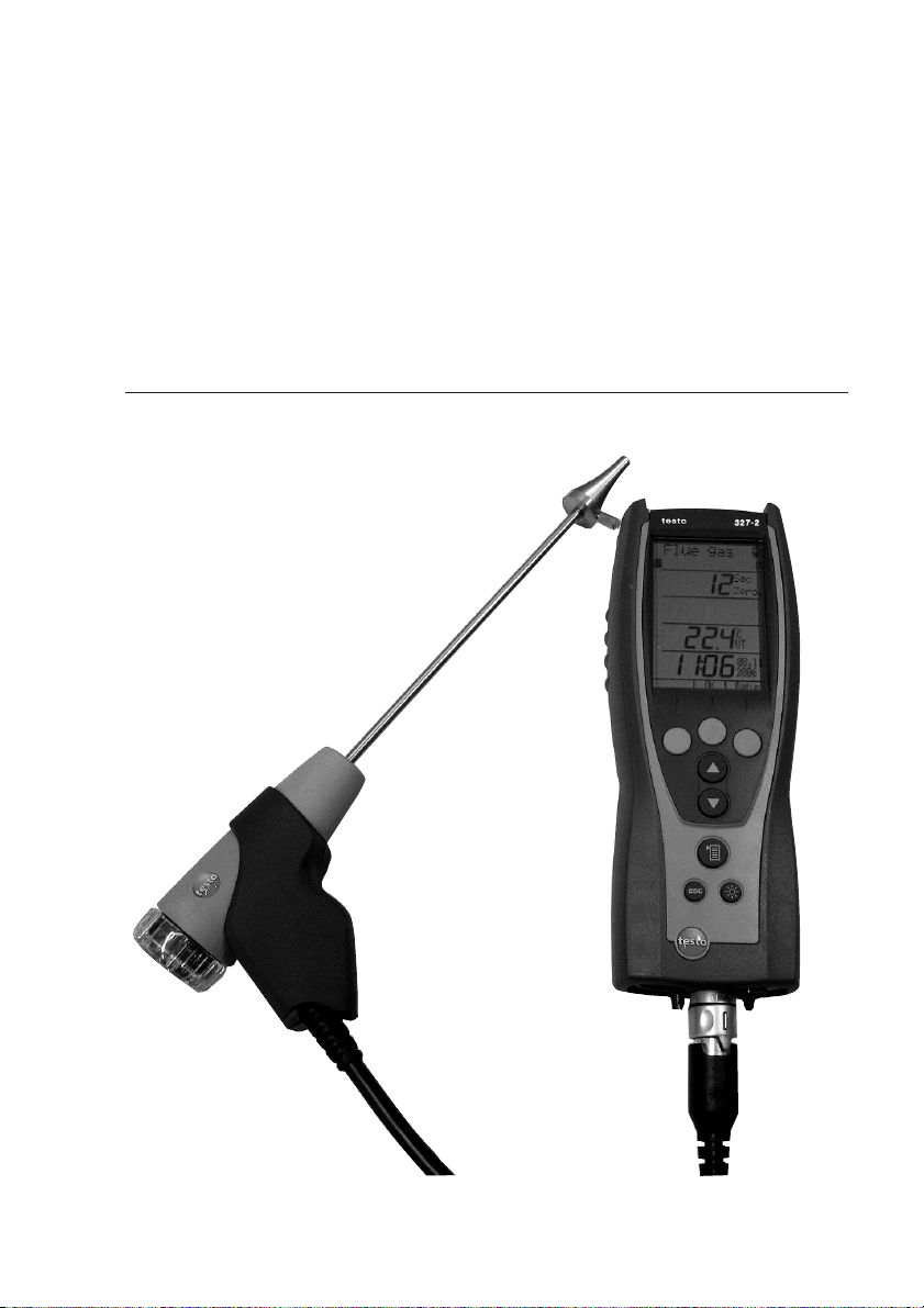
Flue gas analyser, country-specific version GB
Instruction manual en
testo 327
Page 2

Contents2
Contents
Contents ................................................................................................2
Safety and the environment ....................................................................3
EC declaration of conformity ..................................................................7
Product description ................................................................................8
First steps ..............................................................................................9
Using the product ..................................................................................12
Preparing for measurement ....................................................................12
Performing the measurement ..................................................................14
Checking the instrument ........................................................................18
Maintaining the product ........................................................................19
Tips and assistance ..............................................................................25
Accessories and spare parts ................................................................26
Appendix ..............................................................................................27
Page 3
Safety and the environment 3
Safety and the environment
About this document
Please read this documentation through carefully and familiarise yourself with
the product before putting it to use. Keep this documentation to hand so
that you can refer to it when necessary. Hand this documentation on to any
subsequent users of the product.
Pay particular attention to information emphasised by the following symbols:
· With the signal word Warning!:
Warns against hazards which could result in serious physical injury if the
precautionary measures indicated are not taken.
· With the signal word Caution!:
Warns against hazards which could result in minor physical injury or damage
to equipment if the precautionary measures indicated are not taken.
· Additional information.
Avoiding personal injury/damage to equipment
Do not make measurements with the measuring instrument and its sensors
on or near live components unless the instrument is expressly approved for
current/voltage measurements!
Never store the measuring instrument together with solvents and do not use
any desiccants.
Only operate the measuring instrument properly, for its intended purpose
and within the parameters specified in the technical data. Do not use force.
Only carry out the maintenance and repair work that is described in the
documentation. Follow the prescribed steps exactly. Only use original spare
parts from Testo.
Any additional work must only be carried out by authorised personnel.
Testo will otherwise refuse to accept responsibility for the proper functioning
of the measuring instrument after repair and for the validity of certifications.
Temperatures given on probes/sensors relate only to the measuring range of
the sensors. Do not expose handles and feed lines to any temperatures in
excess of 70 °C unless they are expressly permitted for higher temperatures.
deenfresitptsvnl????
Page 4

Specifications4
Products with BluetoothÒ (Option)
Changes or modifications, which are not expressly approved by the responsible
official body, can lead to a withdrawal of operating permission.
Interference with data transfer can be caused by instruments which transmit on
the same ISM band, e.g. microwave ovens, DECT telephony, non-secure
software in cellphones when telephoning, transmitting/receiving text messages
etc.
The use of radio connections is not allowed in e.g. aeroplanes and hospitals.
For this reason, the following point must be checked before entering:
Deactivate Bluetooth function
Main menue - Settings - Buetooth - deactivate Bluetooth (Off)
Protecting the environment
Take faulty rechargeable batteries/spent batteries to the collection points
provided for them.
Send the product back to Testo at the end of its useful life. We will ensure
that it is disposed of in an environmentally friendly manner.
Specifications
Functions and use
The testo 327 is a hand-held measuring instrument for the professional flue gas
analysis of domestic and light commercial gas and oil boilers and appliances.
This includes condensing boilers and gas heaters. The unit is designed to carry
out tests shown in BS 7967, and has a timed tightness test, let by test and a
timed CO function.
These systems can be adjusted using the testo 327 and checked for
compliance with the applicable limit values.
The testo 327 is available in four versions; the scope of function varies
according to the version:
· testo 327 O
· testo 327 CO: Infrared interface
· testo 327-1 (O2, CO): Infrared interface
· testo 327-2 (O2, CO): Infrared / IRDA interface, memory, automatic sensor
: Infrared interface
2
diagnosis, option: Bluetooth (data interface)
Page 5

Specifications 5
Warning The testo 327 must not be used in areas at risk of explosion,
for long-term measurements or as a safety (alarm) device!
The testo 327 with the Bluetooth option may only be operated in countries in
which it is type approved (see Technical Data).
Technical data
Display variables [units] Measuring range/resolution Accuracy/response time
Oxygen, via internal electro-chemical sensor (not 327 CO):
O2content [%],
O2air supply [%],
Reference value O2ref [%] 0...21% / 0.1% ±0.2% / t90 <40s
Carbon monoxide, 327-1:
CO content [ppm, mg/m³] 0...4,000ppm / 1ppm ±20ppm (0...400ppm), ±5% of reading (401...1,000ppm),
(H2share <10%) ±10% of reading (1,001...4,000ppm) / t90 <60s
Carbon monoxide, via internal electro-chemical sensor (only 327-2 with option COH2):
CO content [ppm, mg/m³] 0...8,000ppm / 1ppm ±20ppm (0...200ppm), ±5% v. Mw. (201...2,000ppm),
±10% of reading (2001...8,000ppm) / t90 <40s
Ambient Carbon monoxide, via internal electro-chemical sensor:
Ambient CO content
amCO [ppm] 0...2,000ppm / 1ppm ±10ppm (0...100ppm), ±10% of reading (>100ppm) /
t90 <40s
Temperature, via type K thermocouple of flue gas probe (NiCr-Ni):
Flue gas temperature FT,
Flue gas dew point ATP,
Ambient air AT -40...+600°C / 0.1°C, ±0.5°C (-40...100°C), ±0.5% of reading (>100°C),
-40...1,112°F / 0.1°F ±0.9°F (-40...212°F), ±0.5% of reading (>212°F) /
t98 <50s (TE 0.5mm);<100s (TE 1mm)
Temperature, via differential temperature set 0554 1208:
Flue gas socket T1 [°C, °F],
Sensor socket T2 [°C, °F] -40...+600°C / 0.1°C, ±0.5°C (-40...100°C), ±0.5% of reading (>100°C),
-40...1,112°F / 0.1°F ±0.9°F (-40...212°F), ±0.5% of reading (>212°F) /
t98 <50s (TE 0.5mm);<100s (TE 1mm)
Pressure, via internal differential pressure sensor:
Flue draught Drght [mbar,
hPa, inW, in Hg] -40...40hPa / 0.01hPa ±0.02hPa (-0.50...0.60hPa), ±0.03hPa (0.61...3hPa),
±1.5% of reading (>3hPa) /-
Flue draught Drght, with option
of precision draught [Pa] -100...100Pa / 0.1Pa ±3Pa / -
Pressure and tightness test via internal differential pressure sensor, with differential pressure set 0554 1203:
Differential pressureΔp [hPa] -200...200hPa / 0.1hPa ±0.5hPa (0.0...50.0hPa)
(with option precision ±1% of reading (50.1...100.0hPa)
difference pressure: 0.01hPa) ±1.5% of reading (100.1...200.0hPa)
Efficiency, calculated:
Efficiency
2
η
[%],
Efficiency η+3)[%] 0...120% / 0.1% ±0.2% / -
1)
deenfresitptsvnl????
Page 6

Specifications 6
Display variables [units] Measuring range/resolution Accuracy/response time
Flue gas loss, calculated
1)
Flue gas loss qA2)[%], 0...99.9% / 0.1% - / Flue gas loss qA+3)[%], -20.0...99.9 / 0.1% - / -
Air ratio (not 327 CO)
Air ratio λ[-] 1...20 / 0.01 - / -
Carbon dioxide
CO2content [%] 0...CO
1) Recommended minimum duration of measurement to guarantee correct readings: 3min, 2) Calorific value range not taken into account,
3) Calorific value range taken into account
Calculation formulae for calculated display variables
· See Appendix
Fuels
· Quantity: 5
· Designation/fuel parameters: See Appendix
Ambient conditions
· Operating temperature: -5...45°C/23...113°F
· Storage temperature for measuring instrument:
-20...50°C/-4...122°F,
Li-ion rechargeable battery: 0...35°C/32...95°F
Housing
· Material: ABS/PA/TPU
/ 0.01% - / -
2max
Warranty
· Measuring instrument, flue gas probe: 24 months
· Measuring cells: 24 months
· Thermocouple: 12 months
· Rech. batt.: 12 months
Option Bluetooth (testo 327-2 only)
· Type-designation: BlueNiceCom IV
· Bluetooth Qualified Product Notice:
BNC4_HW2x_SW2xx
· Bluetooth listing identifier: B013784
· Bluetooth listing company: 10274
Range <10m
· Dimensions: 240 x 90 x 58mm
· Weight: Approx. 620g
· Protection class: IP40
Voltage supply
· Current source: Li-ion rechargeable battery
3.7 V/1.4 Ah (0515 0114) / 3.7 V/2.4 Ah (0515 0100),
mains unit 6.3V/1.2A
· Battery life (measuring gas pump on, display light off):
Approx. 4 h (0515 0114) / approx. 10h (0515 0100)
· Battery charge time: Approx. 5-6 h
Display
· Type: Illuminated LCD
· Updating of readings: 1/s
Directives, standards and tests
Option Bluetooth® Certification
EU countries
Belgium (BE), Bulgaria (BG), Denmark (DK),
Germany (DE), Estonia (EE), Finland (FI),France (FR),
Greece (GR), Ireland (IE), Italy (IT), Latvia (LV),
Lithuania (LT), Luxembourg (LU), Malta (MT),
Netherlands (NL), Austria (AT), Poland (PL),
Portugal (PT), Romania (RO), Sweden (SE),
Slovakia (SK), Slovenia (SI), Spain (ES), Czech
Republic (CZ), Hungary (HU), United Kingdom (GB) and
Republic of Cyprus (CY).
Other EFTA Countries
Iceland, Liechtentein, Norway and Switzerland
Non-european countries
Japan, Columbia, Turkey
· EC Directive: 2004/108/EEC
· Tests: EN 50379, Part 2 (O2, °C, hPa),
Part 3 (CO), testo 327-2 with option
COH2 additionally: EN 50379, Part 2
(CO)
CO accuracy: independantly tested to
BS7967
Page 7
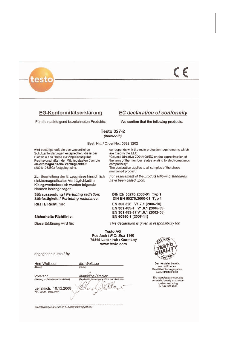
EC conformity declaration 7
EC declaration of conformity
deenfresitptsvnl????
Page 8
Product description8
Product description
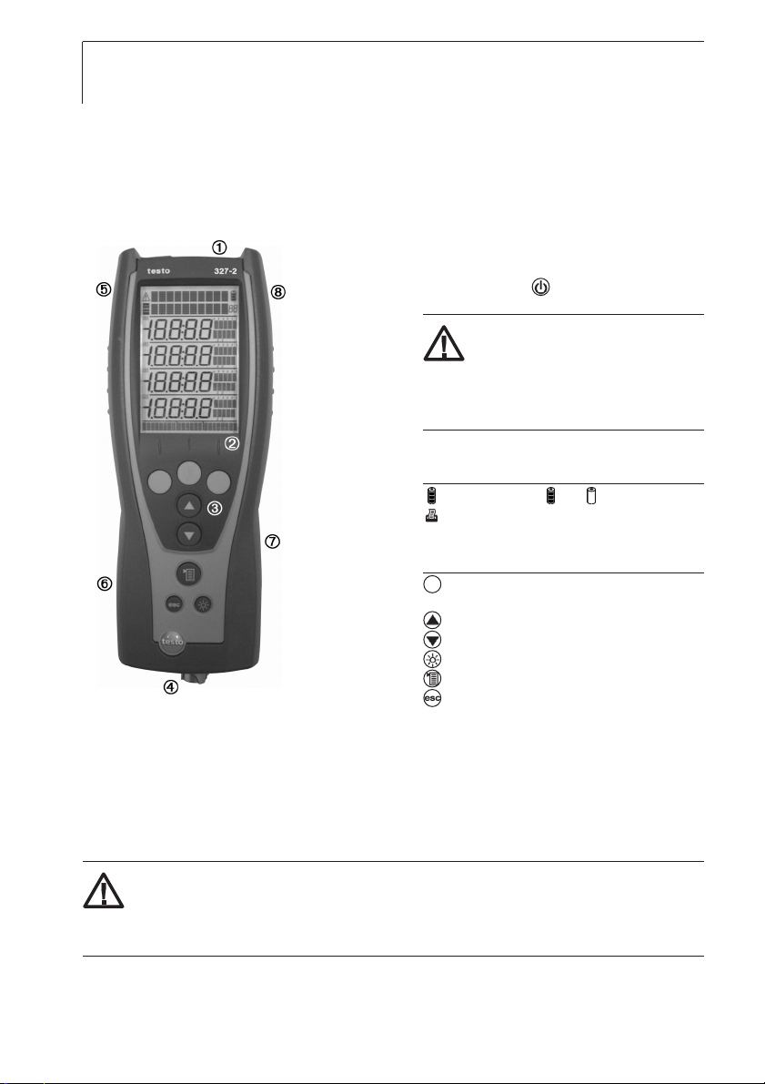
At a glance: Measuring instrument
Head: IR interface (327-2: IRDA) for
connection to Testo protocol printers,
ON/OFF switch ( ),
condensate outlet.
Caution! Risk of injury from
infrared beam!
Do not point infrared beam at people's
eyes!
Display.
Display symbols
: Battery capacity( : full, : empty)
: Print function: sends data
Control keys
Key functions
: Function keys (3x): shows relevant function on
the display.
: Up/down keys: changes display view.
: Light key: switches display light on/off.
: Menu key.
: Cancel key.
Sensor socket for TC temperature probe, flue gas socket for flue gas probe,
gas outlet, mains socket
Sides: window of condensate trap with fill level display
Rear: service compartment (battery, measuring cells)
Rear: magnets for fixing measuring instrument to metallic surfaces.
Warning! Strong magnets can cause damage!
Keep well away from products which could be damaged through the effects of
magnetism (e.g. pacemakers, monitors, computers, credit cards).
Rear: eyelet for attaching a carrying strap (accessory).
Page 9

First steps 9
At a glance: Flue gas probe
Removable filter chamber with window
and particle filter
Probe handle
Connecting cable
Connector for measuring instrument
First steps
Charging rechargeable battery
Charge the rechargeable battery fully before using the measuring instrument.
The rechargeable battery can only be charged at an ambient temperature of
0...+35 °C. If the rechargeable battery pack has discharged completely, the
charging time at room temperature is approx. 5-6 hrs.
Charging tthe rrechargeable bbattery iin tthe mmeasuring iinstrument:
The measuring instrument must be switched off.
1 Connect the plug of the mains unit to the mains unit socket on the
measuring instrument.
2 Connect the mains plug of the mains unit to a mains socket.
- The charging process will start. The charge status will be shown on the
display. The charging process will stop automatically when the
rechargeable battery is fully charged.
deenfresitptsvnl????
Charging tthe rrechargeable bbattery iin ccharger 00554 11087 ((accessory):
Refer to the documentation that comes with the charger.
Page 10

First steps10
Operation with the mains unit
If the mains unit is connected, the measuring instrument is automatically
powered from the mains unit. It is not possible to charge the rechargeable
battery in the measuring instrument during operation.
1 Connect the plug of the mains unit to the mains unit socket on the
measuring instrument.
2 Connect the mains plug of the mains unit to a mains socket.
- The measuring instrument is powered via the mains unit.
- If the instrument is switched off and a rechargeable battery is inserted,
the charging process will start automatically. Switching the measuring
instrument on has the effect of stopping rechargeable battery charging
and the measuring instrument is then powered via the mains unit.
Switching on/off
Switching tthe iinstrument oon:
Press .
- Initialisation phase:
· All display segments are lit (length of time: 3 s).
· Serial number, firmware version, instrument designation, date, time and country-
specific version of instrument are displayed (length of time: 5 s).
- The Measure flue gas option is displayed.
Switching tthe iinstrument ooff:
Press .
- sometimes: The pump starts and the measuring cells are rinsed until the
switch-off thresholds (O
>20 %, other parameters 50 ppm) are reached.
2
Rinsing lasts no more than 2 minutes.
Performing instrument settings
Performing ssettings:
1 Press .
2 Select Settings using / and confirm entry with the OK function key.
Page 11

First steps 11
3 Select the required function using / and confirm entry with the OK
function key.
Functions
1. Displ. seq: selects parameters and units of measurement and assigns a position number for the
display/protocol printouts.
2. Date/Time: sets the date and time
3. Language: sets the language.
4. Printer: sets the printer to be used.
- The selected function is opened and the position number
(Displ. seq function only) or parameter which can be set flashes.
5. Bluetooth (327-2 with option Bluetooth only): activate / deactivate interface.
4 Set the position number (Displ. seq function only)/parameter:
For Displ. seq function only: Select the position number to be changed
using / and confirm with the Change function key.
Alternatively: Delete the position number with Del. and insert a new
position number using Ins..
Displ. seq function: Only parameters and units of measurement which are
assigned to a position number appear in the display and on printouts.
A maximum of 20 position numbers can be activated.
Key functions
· : Change parameters.
· For Date/Time function: changes between hours, minutes, day, month and year.
· For Displ. seq function: changes between parameter and unit of measurement (only available if
there are several units of measurement for the selected parameter).
· OK for Displ. seq function and a flashing position number: confirms setting and moves to next display
position.
· OK for Displ. seq and Finish flashing: confirms settings and leaves the function.
· OK for Date/Time, Language, and Printer: functions: confirms setting and leaves the function.
· esc: leaves the parameter or function without applying the changes.
Example: "Change display position"
The position number to be changed has been selected.
1 Press / several times until the required parameter flashes.
2 Press the or function key to go to the menu for selecting the unit of measurement.
3 Press / several times until the required unit of measurement flashes.
4 Press the OK function key to confirm the setting and move to the next display position.
5 At the end of performing the settings: Press / several times until Finish flashes
(appears after the last position number) and confirm entry with OK.
deenfresitptsvnl????
Page 12

Using the product12
Using the product
Preparing for measurement
Connecting probes/sensors
The instrument needs to detect which probes or sensors are connected, before
switch on. If you fail to do this simply turn off instrument connect probe and
re-start unit.
Connecting tthe pprobes:
Insert the connector into the flue gas
socket and lock by turning it clockwise
gently (bayonet lock).
There must be no more than one extension
lead (0554 1201) between the measuring
instrument and the flue gas probe.
Connecting tthe ssensor:
If no ambient air temperature sensor is connected, the temperature
measured by the thermocouple of the flue gas probe during the zeroing
phase is used as the ambient air temperature. All dependent parameters
are calculated using this value. This method of measuring ambient air
temperature is sufficient for systems dependent on ambient air. However,
ensure that the flue gas probe is near the intake duct of the burner during
the zeroing phase.
If an ambient air temperature sensor is connected, the ambient air
temperature is measured continuously by this sensor.
Insert the connector of the sensor into the sensor socket.
Using the flue gas probe
Checking tthe tthermocouple:
The thermocouple of the flue gas probe must not lie against the probe cage.
Check before use. Bend the thermocouple
back if necessary.
Page 13

Using the product 13
RGS
Aligning tthe fflue ggas pprobe:
The flue gas must be able to flow freely past the thermocouple.
Align the probe by turning it as required.
The tip of the probe must be in the centre of the flue gas flow.
Align the flue gas probe in the flue gas duct
so that the tip is in the centre of the flow
(area of the highest flue gas temperature).
Activating the required functions
Switching tthe iinstrument oon:
Press .
Activating ffuel:
1 Press .
2 Select Fuel using / and confirm entry with the OK function key.
3 Select the fuel to be measured using / and confirm entry with the
OK function key.
deenfresitptsvnl????
Page 14

Using the product14
Activating mmeasuring ffunction:
1 Press .
2 Select Measure using / and confirm entry with the OK function key.
3 Select the required measuring function using / and confirm entry with
the OK function key.
Functions
1. Flue gas: flue gas measurement with flue gas probe and central measurement menu for
displaying/printing out all readings obtained from the various measuring functions.
2. Let by: timed measurement of differential pressure with differential pressure set (accessory).
3. tightness: timed measurement of differential pressure with differential pressure set (accessory).
4. Draught: flue draught measurement with flue gas probe and differential pressure measurement with
gas pressure set (accessory).
5. Smoke/Oild: enter smoke number/oil derivative (only available if a liquid fuel has been activated).
6. HCT: enter the heat carrier temperature.
7. Diff-press: measurement of differential pressure with differential pressure set (accessory).
8. Diff-temp: measurement of differential temperature with differential temperature set (accessory).
9. Ambient CO: timed measurement of ambient CO with flue gas probe.
Flue gas function: When the measuring cells are first called up after the
measuring instrument is switched on, they are zeroed (length of time: 30 s).
Exception: the Ambient CO function has already been started.
During the zeroing phase, the fuel can be selected. Any connected probe
must be in the open air during the zeroing phase!
Performing the measurement
Measuring:
The steps described in the chapter Preparing for measurement have
been completed.
Let by and tightness function: The Diff Press Kit (0554 1203) must be
connected.
Warning! Risk of explosion due to dangerous mixture of gases!
Make sure there are no leaks between the sampling point and the
measuring instrument.
Do not smoke or use naked flames during measurement.
Draught function: The pressure sensors are zeroed when the Draught
function is started (length of time: 5 s). The measuring instrument must
not be pressurised during zeroing!
To help position the flue gas probe in the centre of the flow (area of the
Page 15

Using the product 15
highest flue gas temperature), the flue gas temperature measured is
shown graphically.
Do not measure for longer than 5 minutes, as the readings may fall
outside of the tolerances due to a possible drift of the pressure sensor.
Smoke/Oild function: Only available if a liquid fuel has been activated.
Diff-temp. function: The differential temperature set (0554 1208)
must be connected. The ambient air sensor must be unplugged (located
bottom left of unit) before connecting the T1 sensor. Be aware that the
connector is a firm fit, when disconnecting.
The differential temperature is calculated from T1 - T2.
Diff-press function: The gas pressure set (0554 1203) must be connected.
The pressure sensors are zeroed when the Diff.-press function is started
(length of time: 5 s). The measuring instrument must not be pressurised
during zeroing!
Do not measure for longer than 5 min, as a drift of the pressure sensor
may result in readings outside the tolerance limits.
Ambient CO: When the measuring cells are first started after the measuring
instrument is switched on, they are zeroed (length of time: 30 s).
Exception: The Flue gas function has already been called up.
Any connected probe must be in the open air during the zeroing phase!
The measurement values from the functions Draught, Diff.-temp., Diff.-press
and Smoke/Oild are transferred to the the central measurement menu Flue
gas and must therefore be carried out before the flue gas measurement.
deenfresitptsvnl????
Flue gas function:
1 Start the measurement with the Start function key.
- The current readings are displayed.
Ensure flue is at normal operating temperature and the readings are steady,
before accepting flue gas measurements.
2 Stop the measurement with the Stop function key.
Let by and tightness function:
- The time value is blinking.
1 Set measuring time (from 1 to 15 minutes) using / and confirm with
the Start function key.
- The message
- After zeroing, the message
Zeroing wwithout ooperating ppressure
Attach tto tthe ssystem aand sstart
is displayed.
is displayed.
Page 16

Using the product16
Start the measurement with the Start function key only when the required
2
gas pressure of 10mbar (Let by) or 20mbar (tightness) is displayed.
p1
-
displays the start pressure in mbar, p2displays the actual value in
mbar.
3 After measuring time, the pressure difference is displayed (
p2- p1
on let
by test, p2- p1on tightness test).
Option:
Stop the measurement with the Stop function key.
Draught, Diff.-temp., and Diff.-press functions:
1 Start the measurement with the Start function key.
- The current readings are displayed.
2 Stop the measurement with the Stop function key.
3 Transfer the readings to the central Flue gas measurement menu using the
OK function key.
Smoke/Oild and HCT functions:
Recording values with the smoke pump and manual input:
1 Select the value to be changed using / and confirm with the change
function key.
2 Set the value using / and confirm entry with the OK function key.
3 Once all values have been input, select Finish using / .
4 Transfer the readings to the central Flue gas measurement menu using the
OK function key.
The values entered are not shown in the central Flue gas measurement
menu. However, they can be printed out together with the readings from
other functions.
Recording values with the smoke tester testo 308 and wireless transfer:
- The testo 308 must be in data transfer mode ( lights up).
1 Press function key t308 .
- The values recorded by the smoke tester are transferred.
2 Once all values have been input, select Finish using / .
3 Transfer the readings to the central Flue gas measurement menu using the
OK function key.
The values entered are not shown in the central Flue gas measurement
menu. However, they can be printed out together with the readings from
other functions.
Page 17

Using the product 17
Ambient CO function:
- The time value is blinking.
1
Set measuring time (from 1 to 30 minutes) using / .
2
Start the measurement with the Start function key.
- The following values are displayed:
AmbCO: current ambient CO value in ppm.
aver.:average ambient CO value in ppm. Every minute the average
value is calculated. If the measured value is lower than the min value,
the min value will be set to the current value. If the measured value is
higher than the max value, the max value will be set to the current
value.
min: minimum ambient CO value in ppm.
max: maximum ambient CO value in ppm.
- Alarmlevels:
Current value > 10 ppm: The value blinks (1 sec on / 1 sec off).
Current value > 30 ppm: The value blinks (0.5 sec on / 0.5 sec off).
- After measuring time the average ambient CO value is displayed.
Option:
Stop the measurement with the Stop function key.
Printing rreadings:
To print out the readings recorded in the instrument, you need Testo
protocol printer 0554 0545 or 0554 0547. You must also follow the
operating instructions for the printer!
deenfresitptsvnl????
The Print function key is only available if a printout is possible in the
instrument's current status.
Start the printout with the Print function key.
- Printing out from Flue gas function: All readings taken since the
instrument was last switched on and transferred to the central Flue
gas measurement menu are printed out.
Printing out from other functions: Only those readings taken using the
respective measuring function are printed.
Saving rreadings ((327-22 oonly):
The Save function key is only available if saving is possible in the
instrument's current status.
Start saving with the Save function key.
Page 18

Using the product18
Printing/deleting/displaying mmeasurement ddata ((327-22 oonly):
There are 20 memory locations (Position 1 to Position 20) to which one
measurement data record can be saved per location. Memory locations
that have already been assigned are indicated by the display of the
date/time of saving.
1 Press .
2 Select Memory using / .
- The memory capacity and available memory locations are displayed.
To print the memory: press the Print function key.
To delete the whole memory: press the Del function key and confirm entry
with the Yes function key.
3 Press OK.
4 Select memory location using / .
To display the measurement data record: press the Value function key.
To print the measurement data record: press the Print function key.
To delete the measurement data record: press the Del function.
Transfer ddata tto aa PPocket PPC ((327-22 oonly):
Data can be transferred to a Pocket PC via infrared or Bluetooth.
You must also refer to the documentation that comes with the software.
Checking the instrument
Performing aan iinstrument ddiagnosis:
1 Press .
2 Select Diagnosis using / and confirm entry with the OK function key.
3 Select the required function using / and confirm entry with the OK
function key.
Functions
1. Info: displays instrument information: serial number, instrument temperature, operating hours, qA
version, last service
2. Error: displays list of errors.
3. Rech. batt: displays the battery capacity.
4. Sens. Diag (327-2 only): performs sensor diagnosis.
Key functions for Sens. Diag function (327-2 only)
· : select sensor.
· Read: performs sensor diagnosis and displays results of diagnosis.
Page 19

Maintaining the product 19
Maintaining the product
Condensate trap
The fill level of the condensate trap can be read from the markings on the
condensate trap.
Emptying tthe ccondensate ttrap
Flue Gas condensate consists of a weak mix of acids. Avoid contact with the
skin. Make sure that the condensate does not run over the housing.
Caution! Failure to empty the condensate trap when the fill level is
reached results in condensate entering the sensors and pump. This
voids the warranty and results in costly repairs and replacements.
Do not empty the condensate trap while the flue gas pump is in operation!
1 Keep measuring instrument in an upright
position (condensate outlet pointing upwards).
2 Open the condensate outlet on the
condensate trap: pull out approx. 7 mm to
the stop.
3 Let the condensate run out into a sink.
4 Mop up any remaining drops on the
condensate outlet using a cloth.
5 Close the condensate outlet.
The condensate outlet must be completely
closed, otherwise measuring errors could occur if external air gets in. It is
advisable to empty water trap at regular intervals, (preferably daily).
deenfresitptsvnl????
Page 20

Maintaining the product20
Particle filter
Checking tthe pparticle ffilter:
Replacing tthe pparticle ffilter:
Check the particle filter of the flue gas
probe for contamination at regular intervals:
check visually by looking through the
window of the filter chamber. Replace the
filter if there are signs of contamination.
The filter chamber may contain condensate.
1 Open the filter chamber by turning it gently
anticlockwise.
2 Remove spent filter and fit new filter
(0554 0040).
3 Fit the filter chamber and lock it by turning
it gently clockwise.
Housing
Cleaning tthe hhousing:
Clean the housing with a damp cloth (soap suds) if it is dirty. Do not use
aggressive cleaning agents or solvents!
Rech. batt.
Rechargeable bbattery ccare:
If possible, always discharge the rechargeable battery fully before
recharging it.
Do not store the rechargeable battery for long periods when discharged.
The best storage conditions are at 50 - 80 % charge level and 10 - 20 °C
ambient temperature; charge fully before further use.
Page 21

Maintaining the product 21
Changing tthe rrechargeable bbattery:
The measuring instrument must not be connected to a mains socket via
the mains unit. The measuring instrument must be switched off.
1 Place the measuring instrument on its front.
2 Undo the screws with a cross-head
screwdriver and remove service lid.
3 Open the battery lock by pressing the button
and pushing in the direction of the arrow.
4 Remove the rechargeable battery and insert
new rechargeable battery.
5 Close the battery lock by pressing the
button and pushing against the direction of
the arrow until the battery engages.
6 Replace service lid and fasten with screws.
Measuring cells
Used measuring cells must be disposed of as special waste!
Changing tthe mmeasuring ccells ((327 CCO, 3327 OO2, 3327-11):
A slot bridge (0192 1552) must be inserted in slots which do not have a
measuring cell. Used measuring cells must be disposed of as special waste!
deenfresitptsvnl????
The measuring instrument must be switched off.
1 Place the measuring instrument on its front, facia.
2 Loosen the screws with a cross-head screwdriver and remove service lid.
3 Pull hose connections from the faulty measuring cell.
4 Remove the faulty measuring cell/bridge from the slot.
CO measuring cell only: Remove the shorting
jumper
.
Do not remove shorting jumpers of the new
measuring cells until immediately before installation.
Do not leave the measuring cells without a shorting
jumper for longer than 15 minutes.
5 Insert a new measuring cell in the slot.
6 Attach hose connections to the measuring cell.
7 Replace service lid and fasten with screws.
8 Continue with
calibration of O2 measuring cell
and/or
input of cell
coefficients for CO measuring cell.
Page 22

Maintaining the product22
Calibrating tthe OO2measuring ccell ((327 OO2, 3327-11):
After replacing an O
measuring cell, wait for an stabilisation period of 60
2
minutes to elapse before starting the calibration.
During the calibration, any flue gas probes that are connected must be in the
open air.
1 Press .
2 Select Sensors using / and confirm entry with the OK function key.
3 Select 0
-Sensor using / and confirm entry with + (press
2
simultaneously).
- Instrument performs calibration (30s) and is then ready for use again.
Inputting ccell ccoefficients ffor CCO mmeasuring ccell ((327 CCO, 3327-11):
If you do not enter the correct cell coefficients, you will get incorrect
readings! You will find the cell coefficients on the leaflet enclosed with the
spare measuring cell. If you enter incorrect coefficients:
Abort the process using and enter cell coefficients again.
1 Press .
2 Select Sensors using / and confirm entry with the OK function key.
3 Select CO Sensor using / and confirm entry with + (press
simultaneously).
- The first number of the first cell coefficient flashes.
4 Press Change function key and set number using / .
5 Change to further digits by pressing the function keys one after the
other and confirm entry with OK function key.
- Instrument automatically changes to the second cell coefficient
6 Repeat steps 4 and 5. Confirm the input with the OK function key.
7 Complete the entry with the OK function key.
Replacing mmeasuring ccells, ttesto 3327-22:
The measuring instrument must be switched off.
1 Place the measuring instrument on its front facia.
2 Loosen the screws with a cross-head screwdriver and remove service lid.
3 Pull hose connections from the faulty measuring cell.
4 Remove the faulty measuring cell from the slot.
Page 23

Maintaining the product 23
CO measuring cell only: Remove shorting jumper
(0390 0095, 0390 0109).
Do not remove shorting jumpers of the new
measuring cells until immediately before
installation. Do not leave the measuring cells
without a shorting jumper for longer than
15 minutes.
5 Insert a new measuring cell/bridge in the slot.
6 Attach hose connections to the measuring cell/bridge.
7 Replace service lid and fasten with screws.
After replacing an O2 measuring cell, wait for an stabilisation period of 60
minutes to elapse before starting a new measurement.
Thermocouple
Replacing tthe tthermocouple oof tthe fflue ggas pprobe
1
Loosen and remove halfshell handles ().
2
Turn sealing cap clockwise as far as it will go
and remove (
).
deenfresitptsvnl????
Page 24

Maintaining the product24
3
Unlock halfshell elements and remove ().
4 Remove adaptor and hose (
couple out of its holder (
from thermocouple (
5
Connect lines to the new thermocouple
(
, white -, green +) and push thermocouple
into holder again.
6
Connect adaptor and hose to thermocouple (
Adjust lines and hoses (
7 Attach sealing cap and turn anticlockwise
(as far as possible, note markings).
8 Attach halfshell handles and close screws.
), Push thermo-
) and disconnect cable
).
) and attach halfshells.
).
Page 25

Tips and assistance 25
Tips and assistance
Questions and answers
Measuring instrument switches itself off or will not switch on?
· Rechargeable battery is low: charge battery or connect mains unit.
· On 327-2 models condensate trap is full, red lights indicate.
Battery capacity seems to be faulty?
· Rechargeable battery was repeatedly not fully discharged/charged: discharge rechargeable battery (until
measuring instrument switches itself off) and then charge fully.
---- appears instead of a reading?
· Sensor/probe is not plugged in: connect the sensor/probe
· Sensor/probe or measuring cell faulty: check sensor/probe or measuring cell.
Message: Pump flow rate too high?
· Gas outlet is blocked: make sure that the gas outlet is clear.
Message: ERROR + two-digit no. and service?
Device error: switch off the instrument and contact your dealer or Testo Customer Service.
If the above information does not solve the problem, please contact your dealer
or Testo Customer Service. For contact data, see back of this document or
web page www.testo.com/service-contact
deenfresitptsvnl????
Page 26

Accessories and spare parts26
Accessories and spare parts
Designation Article no.
Probes/sensors
Compact flue gas probe, 180 mm, Ø 6 mm, TC 1 mm, incl. cone, up to 500 °C / 932 °F 0600 9740
Compact flue gas probe, 300 mm, Ø 6 mm, TC 1 mm, incl. cone, up to 500 °C / 932 °F 0600 9741
Thermocouple for compact flue gas probe, 180 mm, 0430 0383
Thermocouple for compact flue gas probe, 300 mm, 0430 0382
O2annular gap probe 0632 1260
Ambient air temperature (AT) probe, 300 mm 0600 9791
Ambient air temperature (AT) probe, 190 mm 0600 9787
Ambient air temperature (AT) probe, 60 mm 0600 9797
Pipe wrap probes 0600 4593
Surface probes 0600 0194
Differential temp kit (adaptor, 2 x pipe wrap probes) 0554 1208
Differential pressure set 054 1203
Pipe wrap probe 0600 0020
Thermocouple adaptor 0440 1261
B1 gas cooker grill probe (BS7967) 300002 7967
B2 angled probe for open flue applications (BS7967) 300001 7967
Spare measuring cells
02measuring cell for testo 327-1 0390 0047
CO measuring cell for testo 327-1 0390 0046
02measuring cell for testo 327-2 0390 0092
CO measuring cell for testo 327-2 0390 0095
CO/H2 measuring cell for testo 327-2 0390 0109
Miscellaneous
Rechargeable battery for testo 327-O2, 327-CO, 327-1 0515 0114
Rechargeable battery for testo 327-2 0515 0100
Protocol printer, IrDA 0554 0547
Spare thermal paper for protocol printer, long-term legibility for up to 10 years 0554 0568
Charger with spare rechargeable battery 0554 1087
Smoke tester for measuring soot in flue gas 0554 0307
Spare particle filter, 10 pcs. 0554 0040
For a complete list of all accessories and spare parts, please refer to the
product catalogues and brochures or look up our website at: www.testo.co.uk
Page 27

Appendix 27
Appendix
Fuel parameters
Fuel CO
MAX (%) [%] [1/K] [1/K] [-] [% by weight][% by weight] [MJ/kg] [MJ/kg]
Natural Gas 11.9 3 0.35 0.39 40 24.4 0.0 53.42 48.16
Light Oil 15.5 3 0.48 0.51 53 13.0 0.0 45.60 42.80
Heavy Oil 15.8 3 0.51 0.54 54 11.5 0.2 42.90 40.50
Propane 13.8 3 0.42 0.45 48 18.2 0.0 50.00 46.30
Butane 14.1 3 0.43 0.46 48 17.2 0.0 49.30 45.80
Kerosene 15.4 3 0.47 0.51 52.36 13.6 0.0 46.56 43.12
Calculation formulae
CCaarrbboonn ddiiooxxiiddee::
CCaarrbboonn mmoonnooxxiiddee::
O2ref Kgr Knet K1 H MH2O Qgr Qnet
2
CO
x (21% - O2)
2max
CO2= C02max: Fuel-specific carbon
CO [mg/m
21%
21%: Oxygen content of the air
O
21% - O2ref
3
] = x CO [ppm] x 1.25 21%: Oxygen content of the air
21% - O
2
O
O
dioxide value
: Measured oxygen
2
content as %
: Measured oxygen
2
content as %
ref: Fuel-specific oxygen
2
reference number as %
deenfresitptsvnl????
RRaattiioo::
CO
CO
x 10O00
2
: carbon dioxide
CO
2
ratio = C0: carbon monoxide
Page 28

Appendix28
Efficiency referred to Gross Efficiency:
Effg = 100 -
Efficiency referred to Nett Efficiency:
Effn= 100 -
EExxcceessss AAiirr ((EExxAAiirr))::
AAiirr rraattiioo:: λλ
CCaarrbboonn mmoonnooxxiiddee
uunnddiilluutteedd::
Kgrx (FT - AT)
()+ ()+ ()
(
CO
2
K
x (FT - AT)
net
()+ ()+ ()
(
CO
2
21%
( -1 )x 100 21%: Oxygen level of air
=
21% - O
CO2max
= C0
CO
uCO = CO x
(MH2O + 9 x H) x (2488 + 2.1 x FT - 4.2 x AT)
(MH2O + 9 x H) x (210 + 2.1 x FT - 4.2 x AT)
2
2
λλ
Q
x 1000
gr
Q
x 1000
net
K1 x CO
CO
+ CO
2
K1 x Qgrx CO
Q
x (CO2+ CO)
net
Kgr/Knet/Qgr/Qnet/K1/MH2O/H:
FT: Flue gas temperature
AT: Ambient temperature
CO: Measured carbon monoxide
CO
O
CO
CO
λ: Calculated air ratio
Fuel-specific factors
value in %
: Calculated carbon dioxide
2
value in %
: Measured oxygen level in %
2
max: Fuel-specific carbon
2
dioxide value
: Calculated carbon dioxide
2
value
: Measured carbon
monoxide value
)
)
FFlluuee ggaass ddeeww ppooiinntt
tteemmppeerraattuurree::
FH20 x PAbs
ln (
ln (
610.78
FH20 x PAbs
610.78
FTP = FH20: Flue gas specific water
)x 234.175
)- 17.08085
PAbs: Absolute pressure in
vapour level in Vol.%
mbar/hPa
Page 29

Notes 29
deenfresitptsvnl????
Page 30

Notes30
Page 31

Notes 31
deenfresitptsvnl????
Page 32

0970 3270 05 en V01.09 en_GB
 Loading...