

Page 1
Instruction manual en
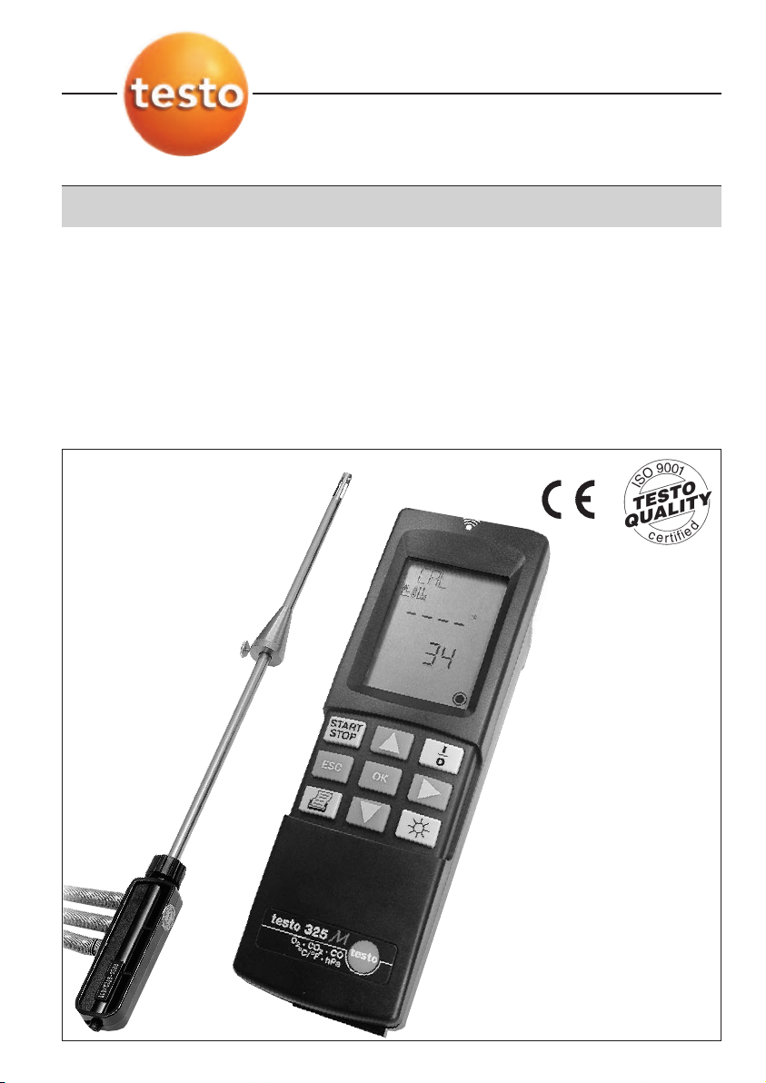
testo 325 M/XL
Flue gas analyser
Page 2

Preface / Copyright
Preface
Dear Customer
Thank you for purchasing a Testo product. We hope you will
enjoy the benefits of this product for a long time to come and
that it will aid you with your work.
Please read this instruction manual carefully and familiarise
yourself with the operation of the instrument before putting it to
use.
If problems should occur which you cannot rectify yourself,
please consult our Customer Service Department or your
nearest distributor. We will do our best to help you quickly and
competently to reduce downtimes.
Copyright
This documentation is subject to the copyright of Testo AG.
Reproduction and use contrary to the legitimate interests of
Testo AG are prohibited without the prior, written consent of the
company.
We reserve the right to modify technical details from the
descriptions, specifications and illustrations contained in this
documentation.
Testo AG
Postfach 11 40
D-79849 Lenzkirch
2
Page 3
General Information
Symbols
Incorrect operation of this instrument could lead to danger. Particularly important information, which
has to be observed when working with this product, is highlighted in this instruction manual as
follows:
Warnings are highlighted by a warning triangle. The Warning title indicates the danger level:
Warning! means death or serious physical injury may occur if the specified safety
measures are not carried out.
Caution! means minor physical injury or damage to property may occur if the specified
Warning title
Notes on special cases and peculiarities in the handling of your unit are indicated by an
exclamation mark.
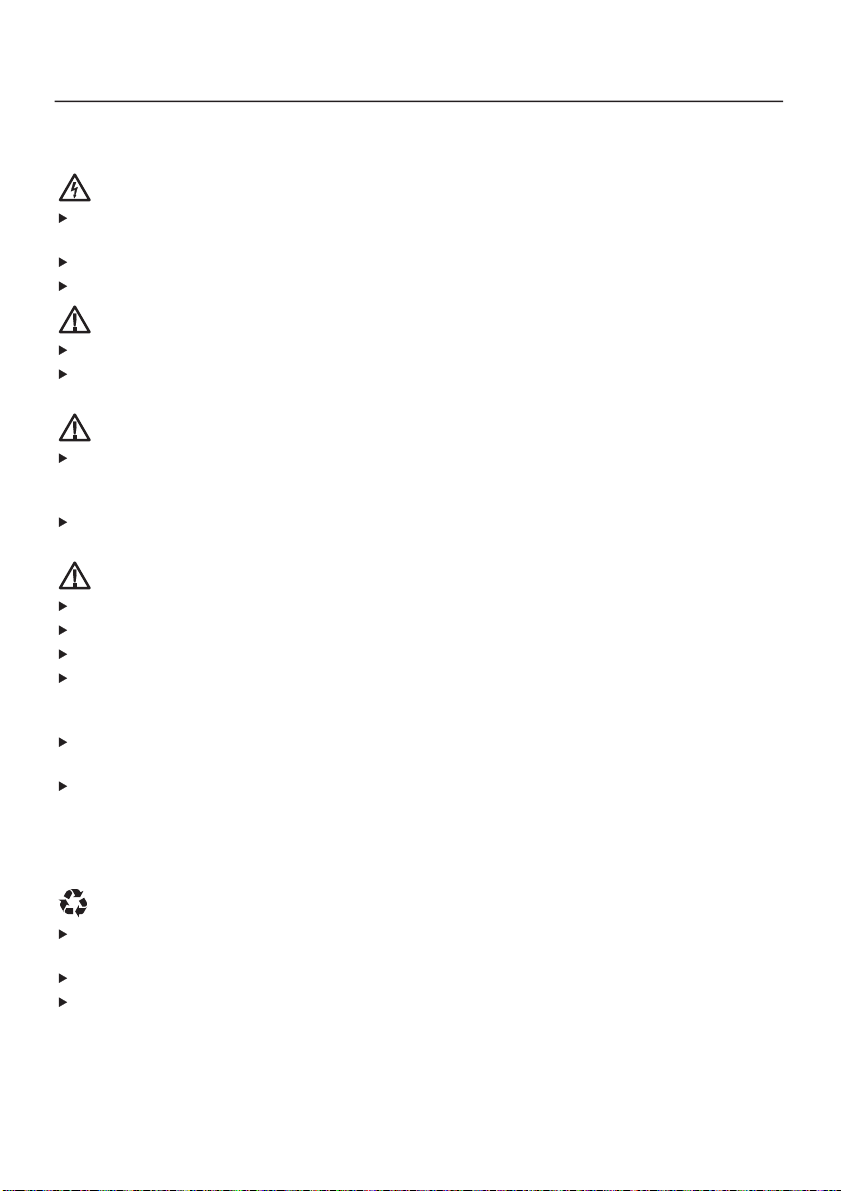
Standards/tests
This product is TÜV approved.
Test Code Number: testo 325 M: TÜV By RgG 218
safety measures are not carried out.
Read all the warnings carefully and carry out all the specified safety measures to avoid
danger.
The conformity certificate confirms that this product fulfills the guidelines in accordance with
89 / 336/EEC.
testo 325 XL: TÜV By RgG 222
3
Page 4

Contents
Preface /Copyright............................................2
General information ..........................................3
Contents............................................................4
1. Basic safety instructions ..................................6
2. Intended use ....................................................7
3. Product description ..........................................8
3.1 Power supply................................................................8
3.2 Dispaly and control elements ......................................8
3.3 Menu overview ..........................................................10
3.4 Gas path ....................................................................10
4. Initial operation................................................11
4.1 Putting in rechargeable batteries / batteries ..............11
4.2 Connecting the mains unit..........................................11
4.3 Connecting sensors / probes ....................................11
5. Basic instructions............................................12
5.1 Switching on ..............................................................12
5.2 Selecting menu items ................................................12
5.3 Measuring ambient air temperature ..........................12
5.4 Measuring flue gas temperature ................................13
5.5 Regular maintenance ................................................13
5.6 Switching off ..............................................................14
6. Settings ..........................................................15
6.1 Selecting fuel..............................................................15
6.2 Setting display sequence ..........................................15
6.3 Selecting units............................................................16
6.4 Setting date/time ........................................................16
7. Measuring ......................................................18
7.1 Measuring flue gases ................................................17
7.2 Measuring pressure....................................................17
7.3 Measuring differential temperature ............................18
7.4 Measuring undiluted CO ............................................19
7.5 Measuring ambient CO ..............................................19
7.6 Printing readings taken ..............................................20
7.7 Saving/reading/deleting readings ..............................21
7.8 Printing saved readings..............................................22
4
Page 5

Contents
8. Maintenance ..................................................23
8.1 Changing rechargeable batteries/batteries ................23
8.2 Emptying the condensate trap ..................................23
8.3 Changing the filter ......................................................24
8.4 Cleaning the analyser ................................................24
8.5 Cleaning the flue gas probe ......................................24
8.6 Changing the thermocouple ......................................25
8.7 Cleaning the flue gas pump ......................................25
8.8 Changing the measuring cells....................................26
9. Troubleshooting ..............................................29
10. Technical data ................................................31
10.1 Measuring ranges and accuracies ............................31
10.2 Other instrument data ................................................32
10.3 Calculation fundamentals ..........................................32
10.4 Calculation formulae ..................................................33
11. Accessories / Spare parts................................34
Short instructions ............................................35
5
Page 6
1. Basic safety instructions
Avoid electrical hazards:
Never make measurements with the unit and its external probes on or near live components
unless the unit is expressly approved for current and voltage mesurements.
Use only the supplied power supply unit when using the instrument under mains power.
Allow only authorised persons to replace damaged mains cables.
Protect the unit/measuring cells:
Never store the unit together with solvents (e.g. acetone).
The condensate trap should be emptied once the maximum line has been reached. Switch off the
pump to empty.
Measure correctly:
Prior to every measurement, check the complete measurement system (probe, condensate trap,
hoses and connections) for leaks in order to avoid incorrect measurements caused by the intake
of air.
Ensure that the gas output in the instrument is always free of obstacles so that the sample gas
can escape unhindered.
Preserve product safety/warranty entitlement:
Operate the instrument only within the parameters specified in the technical data.
Please handle the instrument with care.
Force should never be applied.
The temperature data for the probes only refer to the sensor measuring range. Never subject
handles or pipes to temperatures greater than 70°C unless they are expressly approved for higher
temperatures.
The instrument should only be opened for maintenance and repair work if expressly described in
the Instruction manual.
Only carry out the maintenance and repair work described in the Instruction manual. Please follow
instructions. For safety reasons, only original spare parts from Testo should be used.
Any other work should only be carried out by authorised trained personnel. Otherwise
responsibility for the perfect functioning of the instrument following repairs and for the validity of
approvals will be denied by Testo.
Ensure correct disposal:
The measuring cells contain low concentrations of alkaline solutions and acids. Please dispose of
carefully.
Dispose of defective rechargeable batteries and spent batteries responsibly.
You can return your instrument directly to us at the end of its service life. We will dispose of it
responsibly.
6
Page 7

2. Intended use
Employ the analyser for the following applications only:
testo 325 M / XL is a hand-held instrument for the professional
analysis of flue gas in burners:
- Small-scale burners (oil, gas, wood)
- Low temperature and condensing boilers
- Gas heaters
These systems can be adjusted using testo 325 M / XL and
checked for their adherence to valid limit valids.
testo 325 M / XL can be used to carry out the following tasks:
- Adjustment of O2, CO and CO2values in burners in order to
guarantee smooth operation
- Measurement and adjustment of gas flow pressure in gas
heaters
- Measurement and adjustment of flow and return temperatures
in heating systems
7
Page 8
3. Product description
3.1 Power supply
testo 325 M / XL can be powered as follows:
- 4 batteries (1.5V round cell alkaline IEC LR6 Type AA)
- 4 rechargeable batteries (1.5V IEC KR 15/51 corresp. Type AA)
- Mains connection via mains unit (Part no. 0554 1084)
- Rechargeable battery pack (testo 325 XL only)
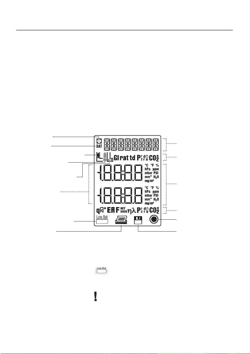
3.2 Display and control elements
Display
Time
Date
Flue gas temperature
Temperature
measurement
Ambient air
temperature
Readings
Battery capacity
Print
Fuel name/
menu item
Parameters
Measuring units
Parameters
Pump on
Save
Battery capacity
A warning flashes in the display if the battery is running low
during rechargeable batttery/battery operation:
Remaining capacity is then approx. 1 hour for batteries, approx.
1 hour for rechargeable batteries
The instrument switches itself off automatically when the
rechargeable battery/battery capacity is too low, in order to
protect from total discharge.
8
Page 9
➀
➃
➆
➁
➂
➅➄
➁➇
➁
➂
3. Product description
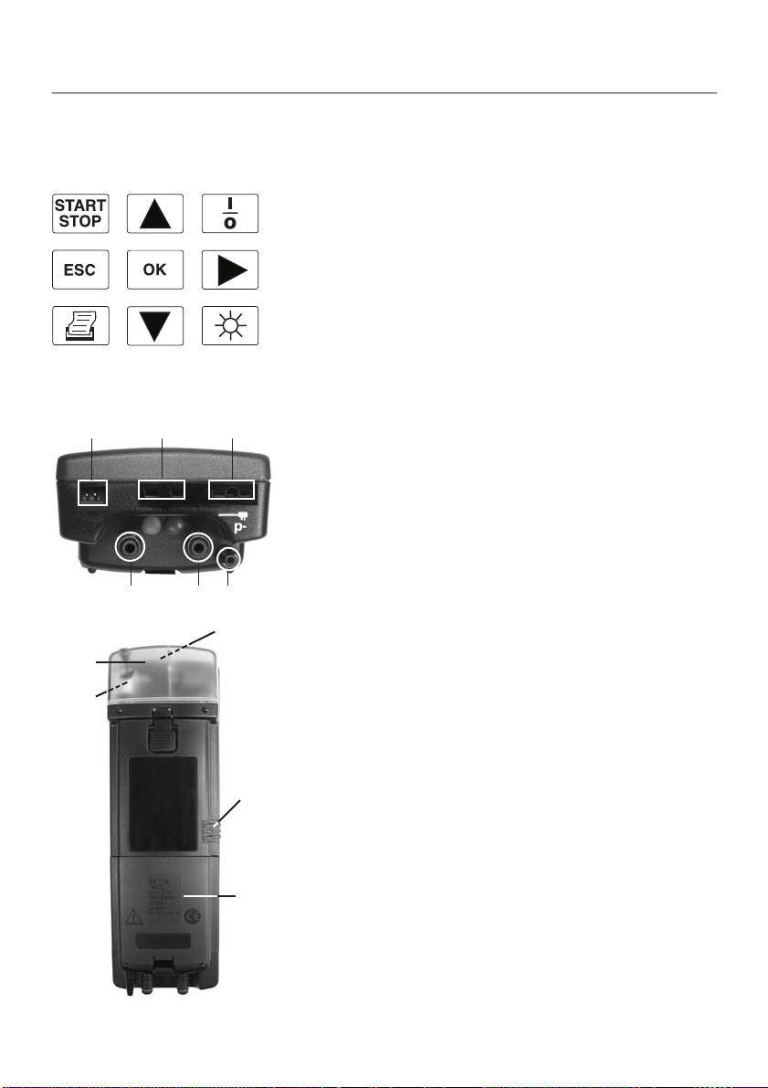
Keyboard
➀ Start/stop flue gas pump
➁ Select display, select menu items
➂ Switch analyser on/off
➃ Interrupt operation, return to superior menu level
➄ Open main menu / sub-menu / menu item, confirm selection
➅ Select parameters
➆ Print current readings
➇ Switch display light on/off
Connections
➀ Mains unit
➁ Probes: ambient air temperature (AT) /temperature T2
➂ Probes: flue gas temperature (FT) / temperature T1
➃ Flue gas (red)
➄ Pressure+ (blue)
➅ Pressure - (p-)
➃
➄
➃
➄➀➅
➀
Other
➀ Infrared interface (on front side)
➁ Gas outlet
➂ Battery compartment
➃ Condensate trap
➄ Filter (behind the condensate trap)
➁
➂
9
Page 10
3. Product description
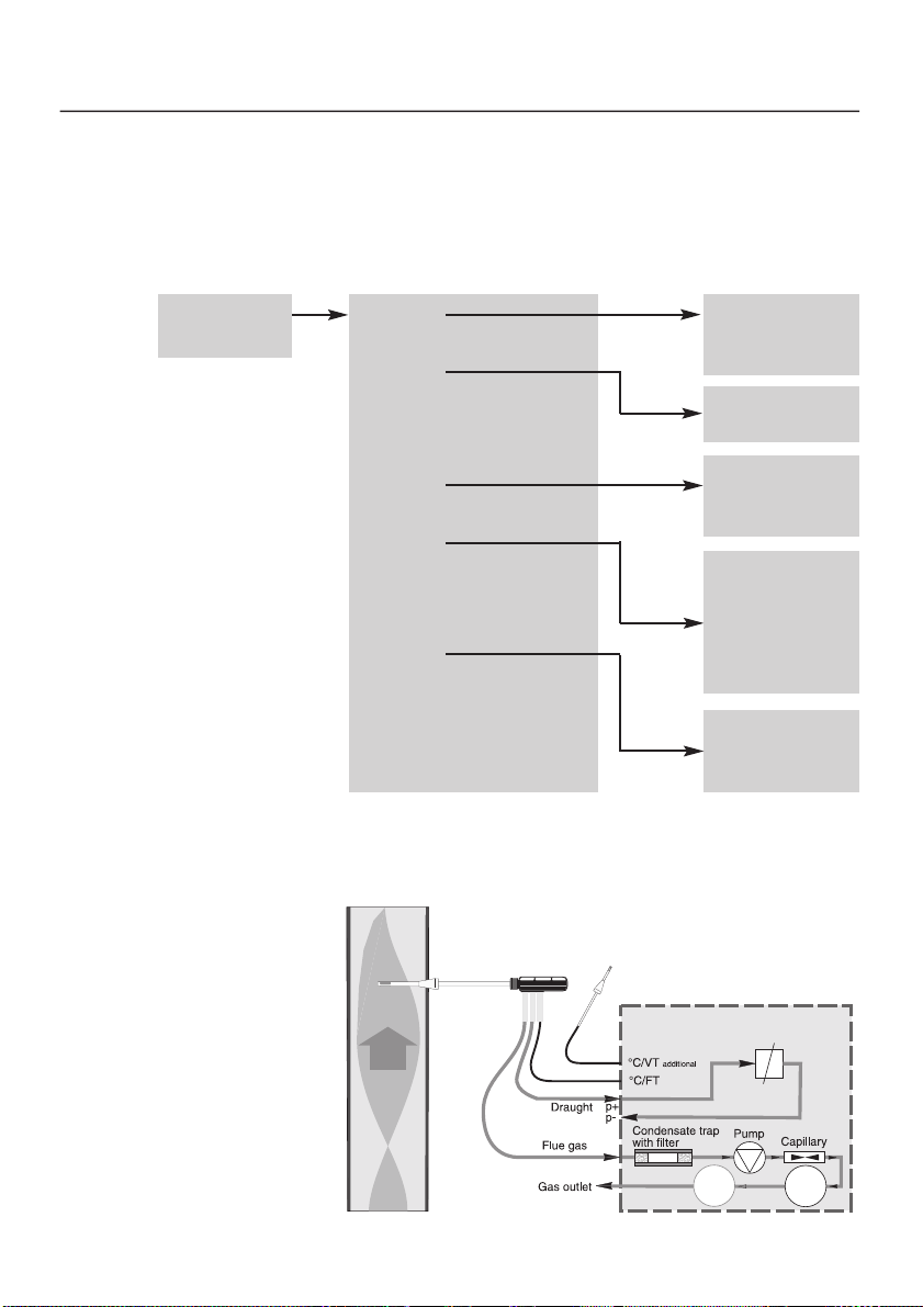
3.3 Menu overview
Measurement
menu Sub-menus
Measurement
view
Main menu
Memory
delta p
delta t
1
memory1
·
·
·
memory20
delta p1
delta p2
View
Fuel
Dat/Clk
Unit
co amb
co undil
1
(testo 325XL only)
3.4 Gas path
RGS
Line 1
·
·
·
Line 12
Nat gas
L oil
H oil
LPG
1
Butane
1
Coal
Pressure
Temperat
Gas
testoter
m
testo 325
p
10
P
CO O
2
Page 11
➀
4. Initial operation
4.1 Putting in rechargeable batteries/
batteries
testo 325XL: Insert and connect rechargeable battery pack. No
other steps are necessary.
testo 325M: 4 batteries are included, please insert prior to
initial operation:
1 Remove battery cover at rear of instrument.
2 Insert batteries correctly (+/-).
3 Close cover on battery compartment.
Refer to Chapter 6, Setting up on page 15 for information on
how to set date/time, fuel and measurement units.
4.2 Connecting the mains unit
Operation via mains unit (0554 1084) is also possible if the
rechargeable batteries/batteries are spent. It is normal for the
mains unit to heat up. If the temperature becomes too high
(e.g. due to a defect in the analyser), the mains unit is
protected from overheating by a thermal safety switch.
The rechargeable battery block in testo 325 XL is recharged
in the analyser when it is switched off and is connected to the
mains (battery symbol flashes during recharging, recharging
stops and battery symbol disappears when rechargeable
battery is full). Conventional rechargeable batteries cannot be
recharged in the analyser.
1 Connect plug to analyser.
2 Connect mains plug to mains.
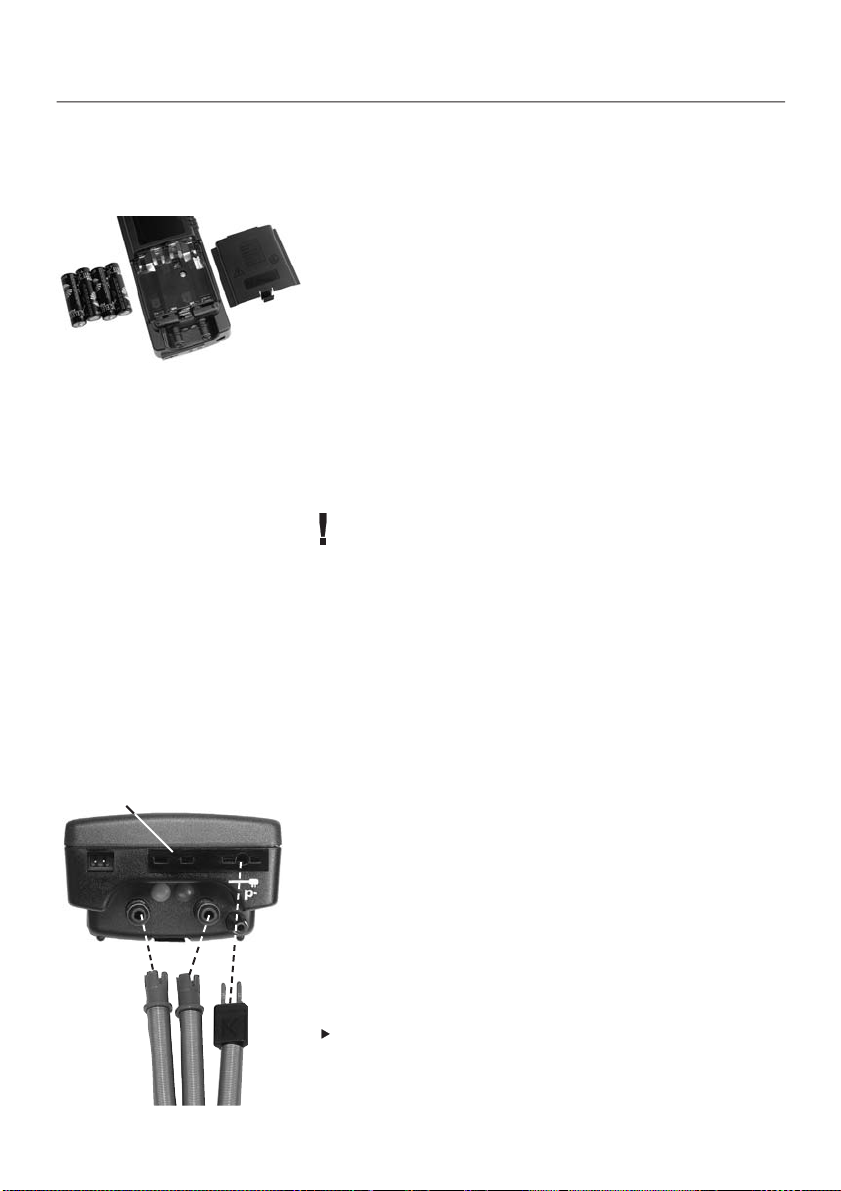
4.3 Connecting sensors/probes
Flue gas probe (accessory)
1 Connect hose for gas (red) to the socket marked by red.
2 Connect hose for pressure (blue) to the pressure+ socket
(blue).
3 Connect flue gas temperature probe pipe to the FT socket.
Ambient air probe (accessory)
Connect ambient air probe pipe to the AT socket ➀.
11
Page 12

5. Basic instructions
➁➀
➂➃
➄
5.1 Switching on
1 Press to switch on analyser.
➀ Display test: All segments in the display light up for approx.
5s.
➁ The software version number and the power is displayed for
3s (rechargeable batteries / batteries: ,
mains unit: ---- ).
➂ Zeroing phase: CAL lights up, pump runs for approximately
60s (remaining time is shown in display).
The flue gas probe must be located in fresh air during
zeroing!
In the case of error messages, refer to “Troubleshooting” on
page 28.
➃ The set fuel flashes in the display
2 Use or to select the required fuel and confirm
with .
➄ Selected fuel now applies.The analyser changes to the
measurement menu and is ready to operate.
12
5.2 Selecting menu items
The pump stops automatically when the main menu is
opened.
1 Open main menu using .
2 Select required menu item via or and confirm via .
If sub-menu is available:
3 Select required menu item via or and confirm via .
Press to go back one menu level.
Page 13

5. Basic instructions
5.3 Measuring ambient air temperature
There are 2 ways to measure the ambient air temperature:
1. Measurement using flue gas probe
If a separate ambient air probe is not connected, the
temperature measured by the flue gas probe thermocouple
during the zeroing phase is used as the ambient air temperature.
All dependent variables are calculated with this value.This type
of ambient air temperature measurement is sufficient for systems
dependent on ambient air.
Ensure that the flue gas probe is located near the intake duct
of the burner during the zeroing phase.
2. Measurement using separate probe
If a separate ambient air probe is connected, the ambient air
temperature is measured continuously by this probe.
5.4 Measuring flue gas temperature
The flue gas temperature is measured via the flue gas probe
thermocouple. The probe pipe has openings at the side so that
the thermocouple is protected and can simultaneously come into
contact with the flue gas.
Ensure that the thermocouple is positioned in the flue gas
flow.
The thermocouple should not be covered by the probe stem
frame. This is the only way to make it possible to measure the
flue gas temperature accurately and consequently to determine
the exact flue gas loss.
The tip of the thermocouple should not touch the protective
casing!
If possible, bend back the tip of the thermocouple.
Inserting probe pipe in flue gas duct
Insert flue gas probe pipe, horizontally if possible, in the
flue gas duct.
Condensation drops running down the probe pipe could lead to a
dramatic drop in the temperature measured.
13
Page 14

5. Basic instructions
5.5 Regular maintenance
Check the level in the condensate trap
Condensate trap overflowing
Damage to pump and measuring cells
Check the level in the condensate trap prior to every
Caution
Check the state of the filter
Caution
Rinse measuring cells
The measuring cells should be rinsed with fresh air after each
measurement :
1 Remove flue gas probe from flue gas duct.
2 Start pump using .
3 Wait until the O2level is above 20.0% and the CO level is
below 50ppm.
4 Press to stop pump.
measurement: Hold the instrument horizontally or
vertically. The condensate trap should be emptied once
the MAX level has been reached (See 8.2 Emptying the
condensate trap, P. 23)!
Filter dirty
Damage to pump!
The state of the filter should be checked on a regular
basis: change the filter when clogged (See 8.3
Changing the filter, P.24).
14
You will find more information about servicing and maintaining
your analyser in Chapter 8. Maintenance, P.23!
5.6 Switching off
The readings stored in the instrument are lost when the
analyser is switched off.
➁➀
In the case of error messages, refer to “Troubleshooting” on
page 29.
Switch off analyser using .
- The analyser automatically rinses the measuring cells if the
O2level drops below 20% or the CO level exceeds 50ppm ➀.
- OFF is displayed for 5s ➁ (press to discontinue switchoff), the analyser then switches off.
Page 15

6. Settings
6.1 Selecting fuel
1 Select Fuel in main menu ➀ and confirm selection
➁➀
using .
- The set fuel flashes in the display ➁.
2 Select required fuel via or and confirm selection using
.
- Selected fuel is accepted and the analyser changes to the
measurement menu.
6.2 Setting display sequence
Selectable parameters:
O
2
Oxygen level
Flue gas temperature (FT)
Ambient air
temperature (AT)
Differential temperature
(FT - AT)
NET
EFF
EFF
Efficiency referred to H
Efficiency referred to H
GROS
rat Ratio
AA
E
CO
2
Excess Air (EXA)
Carbon dioxide
CO Carbon monoxide
uCO Carbon monoxide
undiluted
Air ratio
1
P
P
td Dew point
CO
Pressure (0 to 40hPa)
Pressure (0 to 200hPa)
2
*
CO maximum
1
CO CO ambient
1
(testo 325XL only)
The sequence in which the parameters are shown in the display
can be selected as required. In this way, frequently used
parameters can be combined and then called up quickly
1 Select View in the main menu and confirm selection
with .
- Line1 flashes in the display and the set parameters and units
for line 1 and 2 are shown.
2 Use to select required parameter for line 1.
3 Use to change to Line 2 and select required parameter
u
o
for line 2 with .
4 Set up additional parameters for lines 3 to 12. Repeat
procedure as described in step 3.
5 Confirm settings with .
- Selected settings are accepted and the analyser changes to
the measurement menu.
15
Page 16

6. Settings
➀
➂
6.3 Selecting units
1 Select Unit in the main menu ➀ and confirm
➁
with .
- Pressure flashes and the set unit for pressure is shown in
the display ➁.
2 Select required pressure unit using .
3 Change to Temperat using and select required
temperature unit using .
4 Change to GAS using and select required gas unit using
.
5 Confirm settings using .
- Selected units are accepted and the analyser changes to the
measurement menu.
6.4 Setting date/time
1 Select Dat/Clk in the main menu ➀ and confirm selection
➁➀
selection via .
- The set date is shown and “Day” flashes ➁.
2 Set “Day” using or .
3 Change to “Month” and “Year” using and set using or
respectively.
4 Change to time setting via .
- The set time is shown and “Hour” flashes ➂.
5 Set “Hour” via or .
6 Use to change to “Minutes” and set via or
“Minutes”.
7 Confirm selection via .
- Selected date and time are accepted and the analyser
changes to the measurement menu.
16
Page 17

➀
7. Measuring
Measurements are carried out with the flue gas probe unless
otherwise indicated.
7.1 Measuring flue gases
Select fuel (See: 6.1 Selecting fuel, P. 15).
1 Insert flue gas probe pipe in the flue gas duct.
2 Begin measurement by pressing .
- The pump starts, flashes and the current readings are
displayed ➀.
Use or to change between the different views.
3 End measurement with .
- The pump stops and the last readings are retained in the
analyser until the next flue gas measurement.
7.2 Measuring pressure
With this function, you can measure the draught in a flue gas
channel or the flow pressure in gas heaters.
Draught is measured using the flue gas probe.
You will need the pressure set (Part no. 0554 0315) to
measure the gas flow pressure.
Please observe the following when measuring pressure:
It is only possible to measure pressure if the pump is
switched off.
When the pump is switched off, there is still a dynamic
pressure in the hose which first has to be reduced.
Wait approximately 30 s before starting to measure
pressure.
Remove any condensate in the flue gas probe prior to
measuring pressure (shake probe with tip pointing towards
the ground).
Hold flue gas probe in fresh air during the zeroing phase.
Do not change the position of the analyser while measuring
pressure.
Do not change between rechargeable battery/battery
operation and mains operation when measuring pressure;
fluctuations in the current could influence the measured
result.
Reading display: negative symbol stands for negative
pressure, positive sign stands for positive pressure.
17
Page 18

7. Measuring
➀
➂➃
Measuring draught
1 Select Delta P in the main menu ➀ and confirm selection
➁
via .
2 Select required pressure range:
Delta P1 ( 0 to 40hPa) or Delta P2 (0 to 200hPa) ➁.
3 Confirm selection via .
- The analyser starts zeroing (duration: 5s), CAL lights up in the
display ➂.
4 Once the zeroing phase is complete, insert the flue gas probe
pipe in the flue gas duct.
- The selected pressure range and the current reading are
displayed ➃.
5 End measurement via .
- The last reading is retained in the analyser until the next
draught measurement.
Measuring gas flow pressure
Gas flow pressure is measured in the same way as draught is
measured. Please note the following:
The silicone hoses from the pressure set should only be
connected to the gas heater after the zeroing phase.
18
➀
7.3 Measuring differential temperature
Use this function to measure the flow and return temperature in
heating systems.
You will need 2 pipe clamp probes (Part no. 0628 0020)
for the measurement.
1 Connect probes to analyser.
2 Select Delta t in the main menu ➀ and confirm selection
via .
➁ The temperature at the FT socket (T1) is shown in the top
➁
➂
reading line.
➂ The temperature at the AT socket (T2) is shown in the bottom
reading line.
3 End measurement with .
- The last reading is retained in the analyser until the next
differential temperature measurement.
Page 19

CO undil CO undil
CO amb CO amb
7. Measuring
7.4 Measuring undiluted CO
Always carry out a COundiluted measurement prior to a
flue gas measurement because the values for O2, CO and
in the instrument are overwritten during a COundiluted
➁➀
➁➀
measurement.
1 Select CO undil in the main menu ➀ and confirm via .
- The pump starts automatically and the measured value for
undiluted CO (uCO) is shown ➁.
2 End measurement via .
- The last reading is retained in the instrument until the next
COundiluted measurement.
7.5 Measuring ambient CO
Always carry out an ambient CO measurement before a
flue gas measurement since a value for CO, retained in
the analyser, will be written over when ambient CO is
measured.
Carry out zeroing in fresh air (preferably outdoors) prior to
measuring ambient CO.
1 Select CO amb in the main menu ➀ and confirm selection
with .
- The pump starts automatically and the measured value for
ambient CO ( ) is displayed.
2 End measurement via .
- The last reading is retained in the analyser until the next
ambient CO measurement.
19
Page 20

7. Measuring
-----------------------
➀
➁
NAT GAS
➂
➃
HCT: ______
➄
SmoN: ______
t325XL
-----------------------
30.06.2002 10:05:38
FT 130.6 °C
O2 4,5 %
AT 26.6 °C
AmCO 150 ppm
dP 1 -0.50 hPa
CO2 12.1 %
1.27
CO 101 ppm
7.6 Printing readings taken
You will need the Testo printer 0554 0545 to print the
readings in the analyser. Follow the instructions in the printer
manual.
You will have to be in the measurement menu before you can
start printing and the pump must be switched off.
Start printing procedure by pressing .
- lights up and the following data is printed:
➀ Header: Device name
➁ Date / Time
➂ Selected fuel
➃ Parameters with corresponding reading and unit: the
printout is completed according to the display sequence
set in the instrument (See: 6.2 Setting display sequence,
P. 15), parameters which occur twice are only printed
once.
AmCO = ambient CO, COmx= CO*
➄ HCT: / SmoN: Heat carrier temperature or smoke number
can be entered by hand
➅ Serial number of instrument
-----------------------
# 00000000
➅
-----------------------
20
Page 21

7. Measuring
7.7 Saving/reading/deleting readings
Readings can only be saved with testo 325XL.
20 memory blocks are available (Memory 1 to Memory20) in
which 1 set of readings can be saved.
Blocks which are already occupied are identified by and
the date and time when saved are displayed. Saving on a
memory block which is already occupied means that the
readings that are already saved are overwritten.
➀
➂
1 Select Memory in the main memory ➀ and confirm your
➁
selection with .
2 Select required memory block with or ➁ and confirm
with .
3 Using or choose from Write (save readings) ➂, Read
(read readings) or Delete (delete readings) and confirm
selection with .
If you select Write:
➃
- Clearance query (Really) appears if data is already stored
on the memory block.
Answer clearance query (Really) with .
- The selected memory block name flashes and and
date/time when saved light up ➃. The readings are saved.
-or-
If you select Read:
- The readings contained in the selected memory block are
displayed and flashes.
-or-
If you select delete:
Answer clearance query (Really) with .
- The readings stored in the selected memory block are
deleted.
Press to return to memory selection or measurement
menu.
21
Page 22

7. Measuring
7.8 Print saved readings
You will need the Testo printer 0554 0545 to print the
readings saved in the instrument. Please also follow the
instructions in the printer manual.
1 Select Memory in main memory and confirm selection with
.
2 Select required memory block using or and start
printout via .
-or-
Start printout via while the saved readings are displayed
( is shown).
- is shown and the data is printed.
22
Page 23

➁
➀
8. Maintenance
8.1 Changing rechargeable batteries /
batteries
Switch off the analyser before opening it!
Connect the analyser to the mains unit (accessories),
otherwise the analyser settings (e.g. date/time ...) and the
readings retained in the analyser are lost.
Saved Readings (testo 325XL only) do not get lost!
1 Place analyser on its front and open and remove battery
compartment cover at the back of the analyser.
2 Remove spent rechargeable batteries/batteries from the
battery compartment.
3 Place new rechargeable batteries/batteries in the battery
compartment. Insert correctly (+/-).
- The analyser switches off once the rechargeable batteries /
batteries are inserted!
4 Close cover on battery compartment.
Changing the rechargeable battery block
The rechargeable battery block ( testo 325XL only) is
changed in the same way as the rechargeable
batteries/batteries, however it must be connected to the white
socket in the battery compartment via the plug-in connection
➀ and held in position in the battery compartment via the
available adapter ➁.
8.2 Emptying the condensate trap
Switch off analyser before emptying the condensate trap!
1 Hold analyser with the condensate trap outlet in an upward
position and remove the plugs ➀ somewhat from the outlet
➀
opening.
The condensate is made up a weak acidic mixture. Avoid contact
with skin.
2 Empty condensate into container.
3 Close off outlet using plugs.
23
Page 24

8. Maintenance
➂
➁
➀
8.3 Changing the filter
Change the filter if clogging is visible
Switch off the analyser before changing the filter and empty
the condensate trap (See: 8.2 Emptying condensate trap,
P. 23)!
1 Release condensate trap holder at the back of the analyser
➀ and remove condensate trap ➁.
Only original Testo filters should be used
(Part no. 0554 0040)!
2 Remove clogged filter ➂ and attach new filter.
3 Attach condensate trap to analyser until it clicks into place.
8.4 Cleaning the analyser
The analyser housing should be cleaned with a damp cloth.
Please do not use corrosive cleaning substances or solutions.
Weak household cleaning agents or soap solutions can also
be used.
8.5 Cleaning the flue gas probe
24
➀
➀
➁
Deposits in the flue gas probe pipe can be removed as follows:
1 Release knurled nut in the handle of the flue gas probe by
turning it anti-clockwise ➀ and remove flue gas pipe ➁.
2 Rinse flue gas pipe with hot water and then purge with air or
clean with a brush (e.g. made of brass).
3 Push flue gas pipe over the thermocouple pipe of the flue gas
probe and screw knurled nut tightly by turning it clockwise.
8.6 Changing the thermocouple
1 Unscrew the back bending protection spring on the flue gas
probe handle and the bending protection spring in the
thermocouple plug from their holders by turning them in an
anti-clockwise direction.
2 Release thermocouple cable from the holders in the handle
part and pull the defective thermocouple out of the probe pipe
using a pincers ➀.
Page 25

➁
➀
➂
➁
8. Maintenance
3 Remove thermocouple cable from the slit hose sleeve ➁ and
pull out the defective thermocouple through the bending
protection springs.
4 Guide the new thermocouple through the bending protection
springs and through the handle into the probe pipe.
5 Position thermocouple cable in the holders in the handle.
6 Place thermocouple cable in the slit hose sleeve and press
bending protection springs in the handle and plug in
clockwise direction onto the holders.
8.7 Cleaning the flue gas pump
You will need the Pump Tool (Part no. 0192 0468) to clean the
flue gas pump.
When cleaning the flue gas pump, retained or saved readings
and the instrument settings (Date / Clock...) are lost.
Print out the readings you still need beforehand.
Open instrument
Switch off the instrument before opening and empty the
condensate trap (See: 8.2 Emptying the condensate trap
P. 23)!
Remove the connected sensors, probes and mains units from
the analyser.
Reduce the static charge in your body by touching a
conducting and grounded object. Avoid contact with
instrument electronics.
1 Place analyser on its front and open and remove the battery
compartment cover at the back of the analyser.
2 Remove rechargeable batteries/batteries from the battery
compartment.
3 Release the holder for the condensate trap at the back of the
analyser and remove the condensate trap.
4 Remove filter and release and remove the fixing plate using a
screwdriver ➀.
5 Remove top part of housing from bottom part of housing as
shown in the figure opposite ➁.
Remove flue gas pump and clean
6 Carefully remove flue gas pump from analyser
disconnect flue gas pump plug-in connection using a small
flat nose pincers.
7 Place Pump Tool in the holder in the pump head and then pull
it out.
➂ and
25
Page 26

8. Maintenance
Pump Tool
Pump head
Membrane
Membrane
sensor
Flue gas pump
Measuring cell type Part no.
O2 0390 0085
CO (testo 325M) 0390 0297
CO/H2(testo 325XL) 0390 0245
➀
➂
➀
8 Remove membrane sensor and membrane from pump head ➃.
➃
9 Clean removed parts and the pump plate with spirit or water.
10 Place membrane and membrane sensor in the pump head.
11 Attach pump head and remove Pump Tool.
12 Insert plug-in connection of flue gas pump and plug flue gas
pump into analyser (watch out cables don´t get caught!).
Reassemble analyser
1 Place bottom part of housing on top part of housing and put
back together again by sliding the two parts against each
other.
2 Attach fixing plate, filter and condensate trap.
3 Put in rechargeable batteries/batteries. Insert correctly (+/-)
4 Close cover on battery compartment.
8.8 Changing the measuring cells
Retained or saved (testo 325XL only) readings and
instrument settings (Date / Clock...) are lost when the
measuring cells are changed.
Print the readings which are still needed beforehand.
Only the original Testo measuring cells, listed opposite,
should be used.
Opening the instrument
Proceed as described in the paragraph “Open instrument” in
the Chapter 8.6 Cleaning the flue gas pump, P. 25 and
continue as follows:
6 Remove the 3 screws at the back of the mounting block and
remove the mounting block from the upper part of the
housing ➀.
7 Carefully remove board with display from mounting block ➀.
Changing CO measuring cell in testo 325M
The NO filter also has to be changed when the CO
measuring cell is changed!
➁
Before doing so, carefully remove the short-circuit spring from
the measuring cell contacts of the spare measuring cell.
8 Remove defective CO measuring cell and attach spare
measuring cell to board ➀.
9 Remove filter holder and NO filter
chamber
the measuring chamber (perforated side of filter should point
downward).
➂, clip new NO filter into filter holder and place in
➁ from the measuring
26
Page 27

8. Maintenance
➂
➀
➀ ➁
➁
➁
➁
➀
Changing O2measuring cell in testo 325M
8 Remove screw from O2measuring cell holder and remove
➀
holder ➀.
9 Remove defective O2measuring cell ➁ from measuring
chamber and disconnect plug-in connection.
10 Connect plug-in connection of the spare measuring cell and
place spare measuring cell in the measuring chamber.
11 Attach O2measuring cell holder (place cable through opening
of cell holder) and keep in position using screw.
Changing the CO/H2measuring cell in testo 325XL
8 Remove screw from CO/H2measuring cell holder and remove
holder ➀.
9 Remove defective CO/H2measuring cell ➁ from the
measuring chamber and replace by a spare measuring cell.
Please ensure the measuring cell is correctly aligned: The
lone standing PIN has to be positioned at the right outer
side of the measuring block!
10 Attach CO/H
using screw.
Changing the O2measuring cell in testo 325XL
8 Remove measuring cell holder and measuring cell ➀ from
the measuring chamber ➁ and disconnect the plug-in
connection from the defective O2measuring cell ➂.
9 Place spare measuring cell in the measuring chamber and
place measuring cell holder on the measuring cell (thread
cable through cell holder).
10 Connect plug-in connection of spare measuring cell and
position plug-in connection cable in the holder slot.
Ensure that the connections for measuring cell and pump
do not get mixed up.The measuring cell will be destroyed
if connected incorrectly.
Assembling the analyser
1 Carefully attach board with display to mounting block (ensure
cables are not trapped and ensure that the pressure sensor
connections are connected correctly).
2 Place mounting block in the upper part of the housing and fix
into position using 3 screws (
Proceed as described in the paragraph “Reassemble the
analyser” in 8.7 Cleaning the flue gas pump, P. 25. Now adjust
the new O2 measuring cell and enter the cell coefficients for
the new CO or CO/H2 measuring cell (See page 28)!
measuring cell holder and keep in position
2
➀ long screw, ➁ short screws).
27
Page 28

8. Maintenance
➂
Calibrating the O2measuring cell
Your readings will be incorrect if full adjustment has not been
carried out. Adjustment takes 15 minutes.
If a flue gas probe is connected, it should be located in fresh
air during adjustment.
1 Switch on analyser by pressing and press and
simultaneously while version number and rechargeable
battery/battery capacity are being displayed (duration: 3s)
➁➀
- 02-Calib lights up ➀.
testo 325M:
2 Start calibraiton by pressing .
testo 325XL:
2 Start calibration by pressing twice.
- The pump starts, O2and CAL flash and the minutes until the end
of the calibration are displayed ➁.
- Once calibration is complete, zeroing is carried out and is
then ready for operation.
Entering cell coefficients for CO or CO/H2measuring cell
The readings will be incorrect if the correct cell coefficients
are not entered! You will find the cell coefficients on the sheet
enclosed with the spare measuring cell.
➁➀
If input is incorrect:
Cancel procedure with and enter cell coefficients once
again.
1 Switch on analyser by pressing and press and
simultaneously while version number and rechargeable
battery/battery capacity are being displayed (duration: 3s)
- 02 Calib lights up ➀.
2 Select CO Coeff via ➁ and confirm selection with .
- The first digit in the first cell coefficient flashes ➂.
3 Set digit using or .
4 Advance to the next positions and change to the next cell
coefficients using . Set digits using or .
6 Complete input by pressing .
- The set values are accepted. The analyser carries out zeroing
and is now ready for operation.
28
Page 29

9. Troubleshooting
If defects not described here should occur, please contact your distributor or Testo Customer
Service. You will find contact details in the Warranty booklet or in Internet at
Defects when switching on:
Defect Possible causes Remedy
Analyser cannot Spent rechargeable Change rechargeable batteries/batteries (See Chapter 8.1,
be switched on batteries/batteries P. 23) or connect mains unit (accessory)
flashes and Operating temperature Analyser should be brought into permissible operating
zeroing starts too high or too low temperature range
again
flashes and Flue gas temperature Connect flue gas temperature probe
zeroing probe not attached or or check connection
starts again incorrectly attached
-or-
Thermocouple of flue Change thermocouple
gas temperature probe (See Chapter 8.6 Changing thermocouple, P. 25)
defective
O2flashes and O2value too low because Expose probe to fresh air and run zeroing phase again.
zeroing starts flue gas probe pipe is
again in flue gas duct If not successful: O2measuring cell is defect and has
to be changed (See 8.8 Changing measuring cells, P.26)
CO flashes and Flue gas probe pipe Expose probe to fresh air and run through
zeroing starts in flue gas duct zeroing phase.
again -or- If not successful: C0 / CO/H2measuring cell is defect and
CO value not and has to be changed (See 8.8 Changing measuring cells,
stable P. 26)
Error and an Various Switch off analyser and contact Testo Customer
error number Service Department or contact your nearest dealer
are displayed
www.testo.com
.
29
Page 30

9. Troubleshooting
Defects when measuring
Defect Possible causes Remedy
flashes and Flue gas temperature Connect flue gas temperature probe
---- probe is not or is or check connection
appears incorrectly connected
-or-
Thermocouple in flue Change thermocouple
gas temperature probe (See 8.6 Changing thermocouple, P. 25)
defective
---- is shown Probe not/incorrectly Connect probe or check connection or change filter
in place of connected
reading or defective
02flashes and ---- O2measuring cell defect Change O2measuring cell
appears (See 8.8 Changing measuring cells, P. 26)
C0 flashes and ---- C0 / CO/H2measuring Change C0/ CO/H2measuring cell
appears cell defective (See 8.8 Changing measuring cells, P. 26)
Pump stops and CO value is above the Expose probe to fresh air and start pump via ,
CO flashes switch-off limit to purge the measuring cells.
Caution! Meas. cell can be destroyed if CO value is too high!
Analyser switches Rechargeable batteries/ Change rechargeable batteries/batteries (See Chapter 8.6,
itself off batteries spent P. 23) or connect mains unit (accessory)
Defects when switching off:
Defect Possible causes Remedy
CO and / or CO value too high and / Expose probe to fresh air and wait for rinse to end.
O2flash or O2value too low If not successful: O2or C0/ CO/H2measuring cell is
defective and has to be changed (See Chapter 8.8 Changing
measuring cells, P. 26)
30
Page 31

10. Technical data
10.1 Measuring ranges and accuracies
testo 325 M
Measurement type Meas. range Accuracy Resolution Adapt. time 90%
Temperature
Efficiency 0 to 120% - 0.1% -
Oxygen 0 to 21% ±0.2% 0.1% Approx. 30s
Carbon dioxide 0 to CO
Carbon monoxide20 to 4000ppm < 400ppm ± 20ppm 1ppm Typically 60s
Pressure (Delta P1)30 to 40hPa <3hPa ±0.03hPa 0.01hPa -
Pressure (Delta P2)30 to 200hPa <50hPa ±0.5hPa 0.1hPa -
testo 325 XL
Measurement type Meas. range Accuracy Resolution Adapt. time 90%
Temperature
Efficiency 0 to 120% - 0.1% -
1
-40 to + 600°C <100°C ± 0,5°C 0.1°C Depending on
>100°C ± 0.5% of reading probe used
2max
- 0.1% Approx. 40s
400 to 1000ppm ±5% of reading
>1000ppm ± 10% of reading
>3hPa ± 1.5% of reading
>50hPa ±1.5% of reading
1
-40 to + 1000°C < 100°C ±0.5°C 0.1°C Depending on
>100°C ± 0.5% of reading probe used
Oxygen 0 to 21% ±0.2% 0.1% Approx. 30s
Carbon dioxide 0 to CO
2max
- 0.1% Approx. 40s
Carbon monoxide 0 to 4000ppm < 400ppm ±20ppm 1ppm Typically 40s
400 to 2000ppm ± 5% of read.
>2000ppm ± 10% of reading
Pressure (dP1)
3
0 to 40hPa <3hPa ±0.03hPa 0.01hPa -
>3hPa ± 1.5% of reading
Pressure (dP2)
3
0 to 200hPa <50hPa ±0.5hPa 0.1hPa -
>50hPa ±1.5% of reading
1
Sensor: Thermocouple Type K (NiCr-Ni) to DIN IEC 584 Part 2, Class 1
2
Accuracy data apply to H2level <10%
3
Max. overload: 1000hPa
31
Page 32

10. Technical data
10.2 Additional instrument data
Power supply Batteries: 4x 1.5V round cell alkaline IEC LR6 Type AA
Rech. batt.: 4x 1.5V IEC KR 15/51 Type AA
Rech. batt. 4x 1.5V IEC KR 15/51 Type AA cascaded with plug
block: (testo 325XL only)
Mains unit: 8V/ 1A (Part no. 0554 1084)
Rechargeable battery life at 20°C Approx. 8h (pump on, light off)
Battery life at 20°C Approx. 8h (pump on, light off)
Storage/Transport temperature -20 to + 50°C
Operating temperature -5 to + 45°C
Weight incl. rechargeable battery 450g
Housing material ABS
Dimensions (h x w x l) 52 x68 x216mm
Switch-off threshold for CO 4500ppm
Memory (testo 325XL only) 20 memory blocks
Recharging time/rech. batt. pack 4h (when recharged in analyser)
(testo 325XL only)
Warranty Instrument: 2 years
CO, CO/H2 measuriong cells: 12 months
02 measuring cells: 18 months
Probes and sensors: 24 months
Thermocouples: 6 months
10.3 Calculation fundamentals
Fuels and their calculation formulae
Fuel K
1
K
net
K11Q
gr
1
gr
1
Q
MH2O1H
net
1
Natural gas 0.35 0.39 40 53.42 48.16 0.0 24.4 11.9 3
Light Oil 0.48 0.51 53 45.60 42.80 0.0 13.0 15.5 3
Heavy Oil 0.51 0.54 54 42.90 40.50 0.2 11.5 15.8 3
LPG 0.42 0.45 48 50.00 46.30 0.0 18.2 13.8 3
2
Butane
2
Coal
1
Fuel-specific factor
2
testo 325XL only
0.43 0.46 48 49.30 45.80 0.0 17.2 14.1 3
0.62 0.45 63 26.75 25.50 13.0 4.0 18.4 7
32
1
CO
2maxO2
ref.
Page 33

10. Technical data
10.4 Calculation formulae
The formulae are specified for the instrument version .
CO
x (21% - O2)
CO
2max
CO
x 10000
2
21%
: Maximum carbon dioxide value
2max
specific to fuel
21%: Oxygen level of air
: Measured oxygen level in %
O
2
CO2: Calculated carbon dioxide value in %
Carbon dioxide: CO2= CO
Ratio: rat = CO: Measured carbon monoxide value in ppm
Efficiency
referred to Ho: EFF
Efficiency
referred to H
Excess Air (EXA): E
Air ratio: = CO: Measured carbon monoxide value in %
Carbon monoxide
undiluted: uCO = CO: Measured carbon monoxide value in %
Conversion of ppm in mg/m
CO (mg/m3) = x CO (ppm) x 1.25 21%: Oxygen level of air
Dew point
of flue gas: F
u
()
GROS
: EFF
21% - O
21% - O
= 100 - + +
NET
A
= -1 x 100 21%: Oxygen level of air
()
21% - O
CO
21% - O
2ref
2
ln x 234.175
()
td = factor in vol.%
ln - 17.08085
()
Kgrx (FT - AT)
= 100 - + +
()(
CO
2
K
x (FT - AT)
net
()(
CO
2
21%
2
2max
CO
2
21%
2
3
, referred to O2reference value:
F
x P
H20
Abs
610.78
F
x P
H20
Abs
610.78
(MH2O + 9 x H) x (2488 + 2.1 x FT - 4.2 x AT)
()
(MH2O + 9 x H) x (210 + 2.1 x FT - 4.2 x AT)
()
x 1000
Q
gr
x 1000
Q
net
K
gr/Knet/Qgr/Qnet
FT: Flue gas temperature
AT: Ambient temperature
CO: Measured carbon monoxide value in %
: Calculated carbon dioxide value in %
CO
2
: Measured oxygen level in %
O
2
CO2: Calculated carbon dioxide value in %
21%: Oxygen level of air
: Measured oxygen level in %
O
2
: Measured oxygen level in %
O
2
:O2 reference value in %
O
2ref
: Fuel-dependent water vapour
H20
: Absolute pressure in mbar/hPa
P
abs
/K1/MH2O/H: Fuel-specific factors
(fuel-specific)
K1 x CO
()
+ CO
CO
2
K1 x Qgrx CO
()
x (CO2+ CO)
Q
net
33
Page 34

11. Accessories/ Spare parts
Name Part no.
Flue gas probes and temperature probes
Standard flue gas probe, 180mm 0600 9544
Standard flue gas probe, 300mm 0600 9542
TÜV approved flue gas probe, 180mm 0600 9543
TÜV approved flue gas probe, 300mm 0600 9546
Flexible flue gas probe, 300mm 0600 9440
High temperature probe, 300mm, 1000°C 0600 8540
Dual wall clearance probe 0632 1244
Mini ambient air probe 0600 9798
Ambient air probe 0600 9788
Pipe clamp probe with velcro for pipe diameter to max. 120mm 0628.0020
Measuring cells
O2measuring cell for testo 325 M/ XL 0390 0085
CO measuring cell for testo 325 M incl. NO filter (0133 0069) 0390 0297
CO/ H2 measuring cell for testo 325 XL 0390 0245
Case
Aluminium case 0516 0325
Transport case (plastic) 0516 3250
System case (plastic) 0516 0326
Printer
Testo printer 0554 0545
Other
PE filter (10 off) 0554 0040
Printer paper (6 rolls) 0554 0569
Spare rechargeable battery for testo 325 XL 0515 0104
Pump membrane 0193 0072
Pump Tool (pump disassembly tool) 0192 0468
Thermocouple for probe 0600 9546 0430 0073
Thermocouple for probe 0600 8540 0430 0074
Thermocouple for probe 0600 9544 0430 0070
Thermocouple for probe 0600 9542 0430 0071
Thermocouple for probe 0600 9543 0430 0072
Hose connection set 0554 0315
Probe stop 0170 9051
SoftCase incl. magnetic plate 0516 2572
Mains unit (230V) 0554 1084
34
Page 35

Short instructions
Short instructions for testo 325 M / XL
Please also follow instructions in Instruction manual
Connections
➂
➁
➃
➄➀➅
Switching on instrument and selecting fuel
2 Set fuel using or and confirm selection by pressing .
- Instrument changes to measurement menu and is ready to operate.
Switching off analyser
1 Press to switch off analyser.
2 Wait on automatic rinse.
-
OFF is displayed for 5 s and then the analyser switches off.
Switching background light on/off
Switch background light on or off by pressing .
Selecting menu item
1 Open main menu by pressing .
2 Use / to select menu item and confirm selection via .
If sub-menu is available:
3 Select menu item via / and press to confirm.
Press to go back one menu level.
Setting date/time
1 Select Dat/Clk in main menu and press to confirm.
2 Set value via / , change to next value via .
3 Press to confirm settings.
➀ Mains unit
➁ Probes: Ambient air
temperature (AT) / temperature T2
➂ Probes: Flue gas temperature
(FT) / Temperature T1
➃ Flue gas inlet (red)
➄ Pressure + (blue)
➅ Pressure - (p-)
1 Switch on analyser via .
- The following appear:
display test, software version/
power, zeroing phase.
- Instrument changes to fuel
selection.
35
Page 36

Selecting uunits
11
Select
Unit in main menu and press to confirm.
22
Select parameter via / and confirm selection via .
33
Set unit via , change to next parameter via .
44
Press to confirm settings.
Measuring fflue ggases
11
Press to start measurement.
22
Press / to change between the options possible.
33
Press to end measurement.
Measuring ddraught
11
Select
Delta P in main menu and press to confirm.
22
Use / to select pressure range
Delta P1 (0 to 40hPa) or
Delta P2 (0 to 200hPa) and press to confirm.
- The analyser runs zeroing.
33
Insert probe pipe in flue gas duct.
- The current reading is displayed.
44
Press to end measurement.
Measuring ggas fflow ppressure
Pressure set (0554 0315) required. Procedure same as for draught
measurement.
Printing rreadings ttaken
Testo printer (0554 0545) required.
Start printing by activating in measurement menu.
Saving/reading/deleting rreadings ((
testo 325XL
only)
11
Select Memory in main menu and press to confirm.
22
Use / to select memory block and confirm via .
33
Select
Write, Read or Delete via / and press to
confirm.
Confirm clearance query with .
Printing ssaved rreadings ((
testo 325XL
only)
Testo printer (0554 0545) required.
11
Display readings (See: saving/reading readings).
22
Activate to start printing.
testo AG
Postfach 11 40, D-79849 Lenzkirch
Testo-Straße 1, D-79853 Lenzkirch
Tel. (0 76 53) 6 81 - 0
Fax (0 76 53) 6 81 - 1 00
E-Mail: info@testo.de
http://www.testo.de
0971.3257/01/T/dr/01.04.2004
 Loading...