

TESTO 325M, 325XL Instruction Manual
Instruction manual en
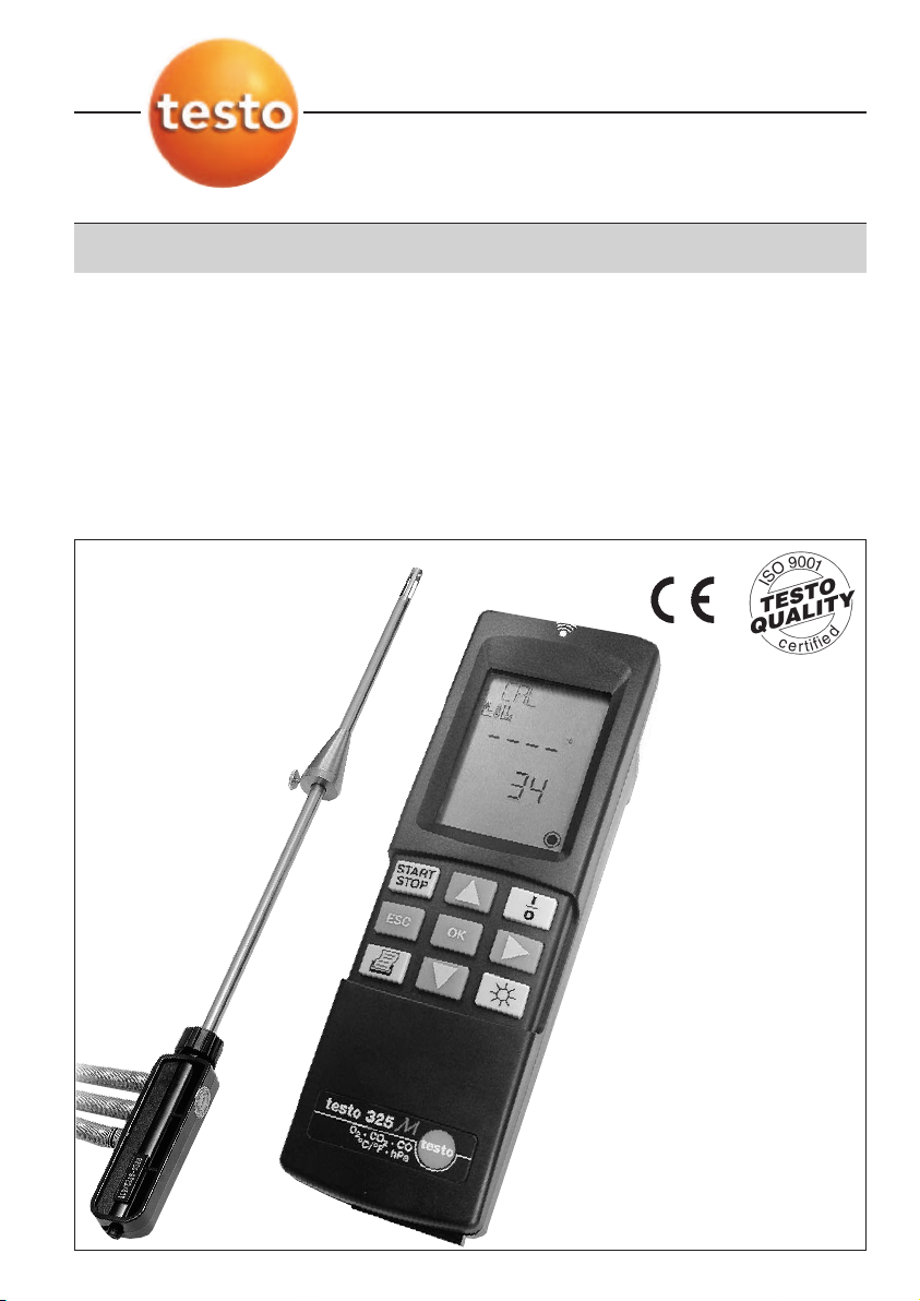
testo 325 M/XL
Flue gas analyser

Preface / Copyright
Preface
Dear Customer
Thank you for purchasing a Testo product. We hope you will
enjoy the benefits of this product for a long time to come and
that it will aid you with your work.
Please read this instruction manual carefully and familiarise
yourself with the operation of the instrument before putting it to
use.
If problems should occur which you cannot rectify yourself,
please consult our Customer Service Department or your
nearest distributor. We will do our best to help you quickly and
competently to reduce downtimes.
Copyright
This documentation is subject to the copyright of Testo AG.
Reproduction and use contrary to the legitimate interests of
Testo AG are prohibited without the prior, written consent of the
company.
We reserve the right to modify technical details from the
descriptions, specifications and illustrations contained in this
documentation.
Testo AG
Postfach 11 40
D-79849 Lenzkirch
2
General Information
Symbols
Incorrect operation of this instrument could lead to danger. Particularly important information, which
has to be observed when working with this product, is highlighted in this instruction manual as
follows:
Warnings are highlighted by a warning triangle. The Warning title indicates the danger level:
Warning! means death or serious physical injury may occur if the specified safety
measures are not carried out.
Caution! means minor physical injury or damage to property may occur if the specified
Warning title
Notes on special cases and peculiarities in the handling of your unit are indicated by an
exclamation mark.
Standards/tests
This product is TÜV approved.
Test Code Number: testo 325 M: TÜV By RgG 218
safety measures are not carried out.
Read all the warnings carefully and carry out all the specified safety measures to avoid
danger.
The conformity certificate confirms that this product fulfills the guidelines in accordance with
89 / 336/EEC.
testo 325 XL: TÜV By RgG 222
3

Contents
Preface /Copyright............................................2
General information ..........................................3
Contents............................................................4
1. Basic safety instructions ..................................6
2. Intended use ....................................................7
3. Product description ..........................................8
3.1 Power supply................................................................8
3.2 Dispaly and control elements ......................................8
3.3 Menu overview ..........................................................10
3.4 Gas path ....................................................................10
4. Initial operation................................................11
4.1 Putting in rechargeable batteries / batteries ..............11
4.2 Connecting the mains unit..........................................11
4.3 Connecting sensors / probes ....................................11
5. Basic instructions............................................12
5.1 Switching on ..............................................................12
5.2 Selecting menu items ................................................12
5.3 Measuring ambient air temperature ..........................12
5.4 Measuring flue gas temperature ................................13
5.5 Regular maintenance ................................................13
5.6 Switching off ..............................................................14
6. Settings ..........................................................15
6.1 Selecting fuel..............................................................15
6.2 Setting display sequence ..........................................15
6.3 Selecting units............................................................16
6.4 Setting date/time ........................................................16
7. Measuring ......................................................18
7.1 Measuring flue gases ................................................17
7.2 Measuring pressure....................................................17
7.3 Measuring differential temperature ............................18
7.4 Measuring undiluted CO ............................................19
7.5 Measuring ambient CO ..............................................19
7.6 Printing readings taken ..............................................20
7.7 Saving/reading/deleting readings ..............................21
7.8 Printing saved readings..............................................22
4

Contents
8. Maintenance ..................................................23
8.1 Changing rechargeable batteries/batteries ................23
8.2 Emptying the condensate trap ..................................23
8.3 Changing the filter ......................................................24
8.4 Cleaning the analyser ................................................24
8.5 Cleaning the flue gas probe ......................................24
8.6 Changing the thermocouple ......................................25
8.7 Cleaning the flue gas pump ......................................25
8.8 Changing the measuring cells....................................26
9. Troubleshooting ..............................................29
10. Technical data ................................................31
10.1 Measuring ranges and accuracies ............................31
10.2 Other instrument data ................................................32
10.3 Calculation fundamentals ..........................................32
10.4 Calculation formulae ..................................................33
11. Accessories / Spare parts................................34
Short instructions ............................................35
5
1. Basic safety instructions
Avoid electrical hazards:
Never make measurements with the unit and its external probes on or near live components
unless the unit is expressly approved for current and voltage mesurements.
Use only the supplied power supply unit when using the instrument under mains power.
Allow only authorised persons to replace damaged mains cables.
Protect the unit/measuring cells:
Never store the unit together with solvents (e.g. acetone).
The condensate trap should be emptied once the maximum line has been reached. Switch off the
pump to empty.
Measure correctly:
Prior to every measurement, check the complete measurement system (probe, condensate trap,
hoses and connections) for leaks in order to avoid incorrect measurements caused by the intake
of air.
Ensure that the gas output in the instrument is always free of obstacles so that the sample gas
can escape unhindered.
Preserve product safety/warranty entitlement:
Operate the instrument only within the parameters specified in the technical data.
Please handle the instrument with care.
Force should never be applied.
The temperature data for the probes only refer to the sensor measuring range. Never subject
handles or pipes to temperatures greater than 70°C unless they are expressly approved for higher
temperatures.
The instrument should only be opened for maintenance and repair work if expressly described in
the Instruction manual.
Only carry out the maintenance and repair work described in the Instruction manual. Please follow
instructions. For safety reasons, only original spare parts from Testo should be used.
Any other work should only be carried out by authorised trained personnel. Otherwise
responsibility for the perfect functioning of the instrument following repairs and for the validity of
approvals will be denied by Testo.
Ensure correct disposal:
The measuring cells contain low concentrations of alkaline solutions and acids. Please dispose of
carefully.
Dispose of defective rechargeable batteries and spent batteries responsibly.
You can return your instrument directly to us at the end of its service life. We will dispose of it
responsibly.
6

2. Intended use
Employ the analyser for the following applications only:
testo 325 M / XL is a hand-held instrument for the professional
analysis of flue gas in burners:
- Small-scale burners (oil, gas, wood)
- Low temperature and condensing boilers
- Gas heaters
These systems can be adjusted using testo 325 M / XL and
checked for their adherence to valid limit valids.
testo 325 M / XL can be used to carry out the following tasks:
- Adjustment of O2, CO and CO2values in burners in order to
guarantee smooth operation
- Measurement and adjustment of gas flow pressure in gas
heaters
- Measurement and adjustment of flow and return temperatures
in heating systems
7
3. Product description
3.1 Power supply
testo 325 M / XL can be powered as follows:
- 4 batteries (1.5V round cell alkaline IEC LR6 Type AA)
- 4 rechargeable batteries (1.5V IEC KR 15/51 corresp. Type AA)
- Mains connection via mains unit (Part no. 0554 1084)
- Rechargeable battery pack (testo 325 XL only)
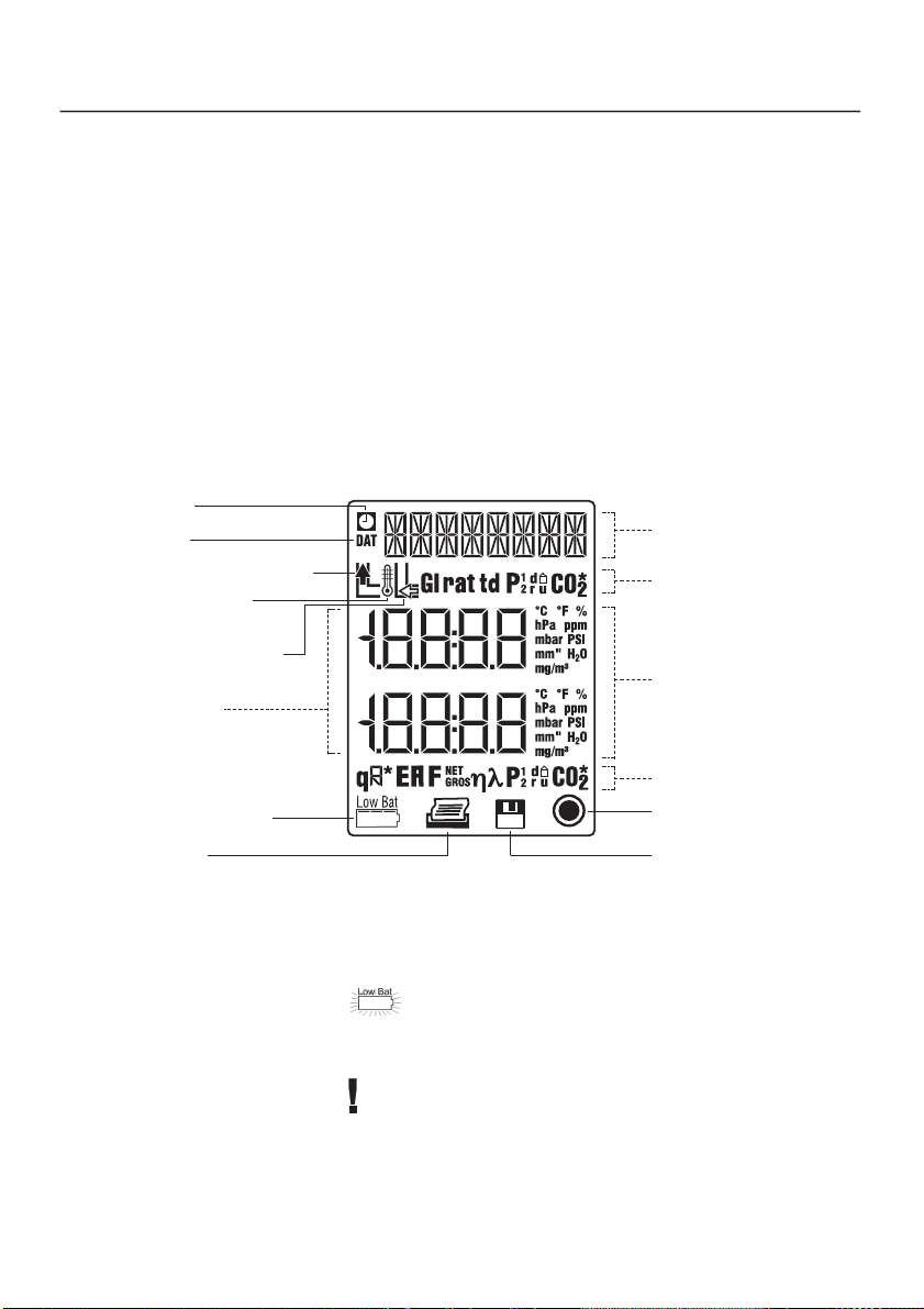
3.2 Display and control elements
Display
Time
Date
Flue gas temperature
Temperature
measurement
Ambient air
temperature
Readings
Battery capacity
Print
Fuel name/
menu item
Parameters
Measuring units
Parameters
Pump on
Save
Battery capacity
A warning flashes in the display if the battery is running low
during rechargeable batttery/battery operation:
Remaining capacity is then approx. 1 hour for batteries, approx.
1 hour for rechargeable batteries
The instrument switches itself off automatically when the
rechargeable battery/battery capacity is too low, in order to
protect from total discharge.
8
➀
➃
➆
➁
➂
➅➄
➁➇
➁
➂
3. Product description
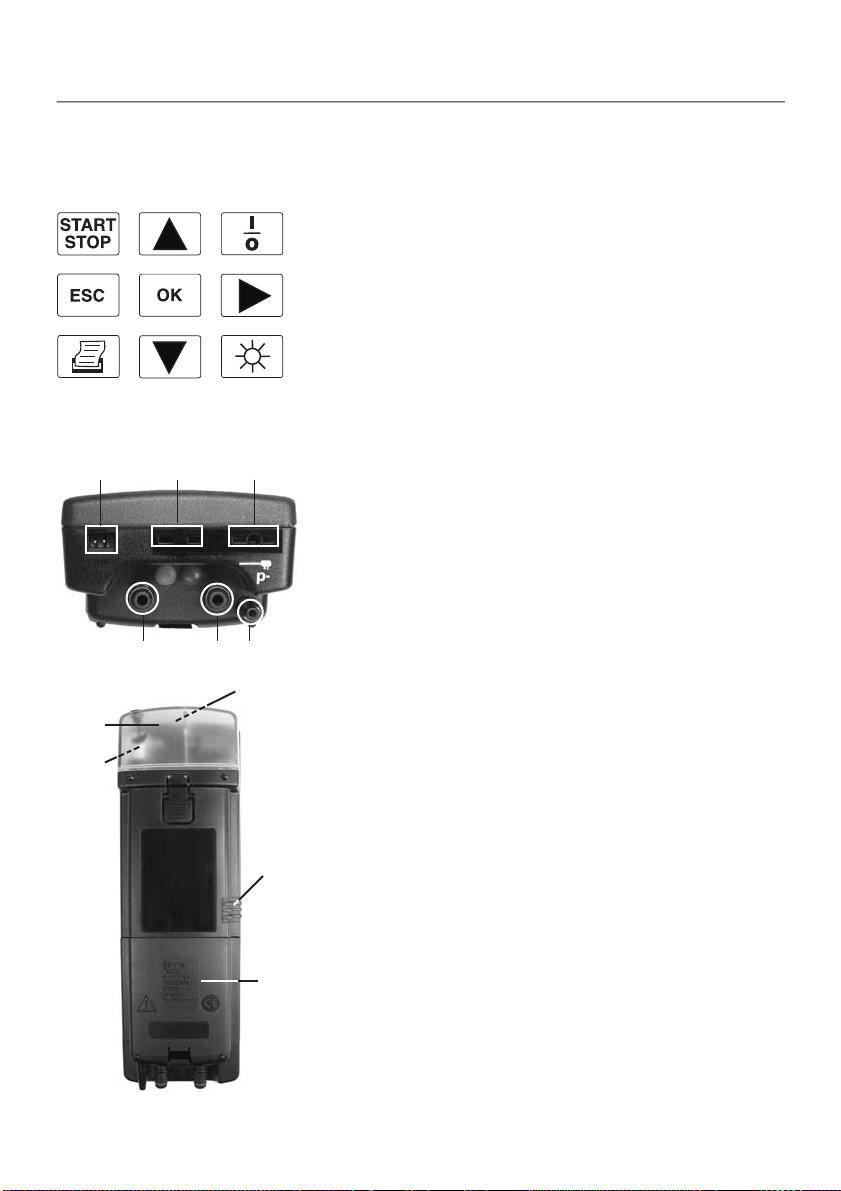
Keyboard
➀ Start/stop flue gas pump
➁ Select display, select menu items
➂ Switch analyser on/off
➃ Interrupt operation, return to superior menu level
➄ Open main menu / sub-menu / menu item, confirm selection
➅ Select parameters
➆ Print current readings
➇ Switch display light on/off
Connections
➀ Mains unit
➁ Probes: ambient air temperature (AT) /temperature T2
➂ Probes: flue gas temperature (FT) / temperature T1
➃ Flue gas (red)
➄ Pressure+ (blue)
➅ Pressure - (p-)
➃
➄
➃
➄➀➅
➀
Other
➀ Infrared interface (on front side)
➁ Gas outlet
➂ Battery compartment
➃ Condensate trap
➄ Filter (behind the condensate trap)
➁
➂
9
3. Product description
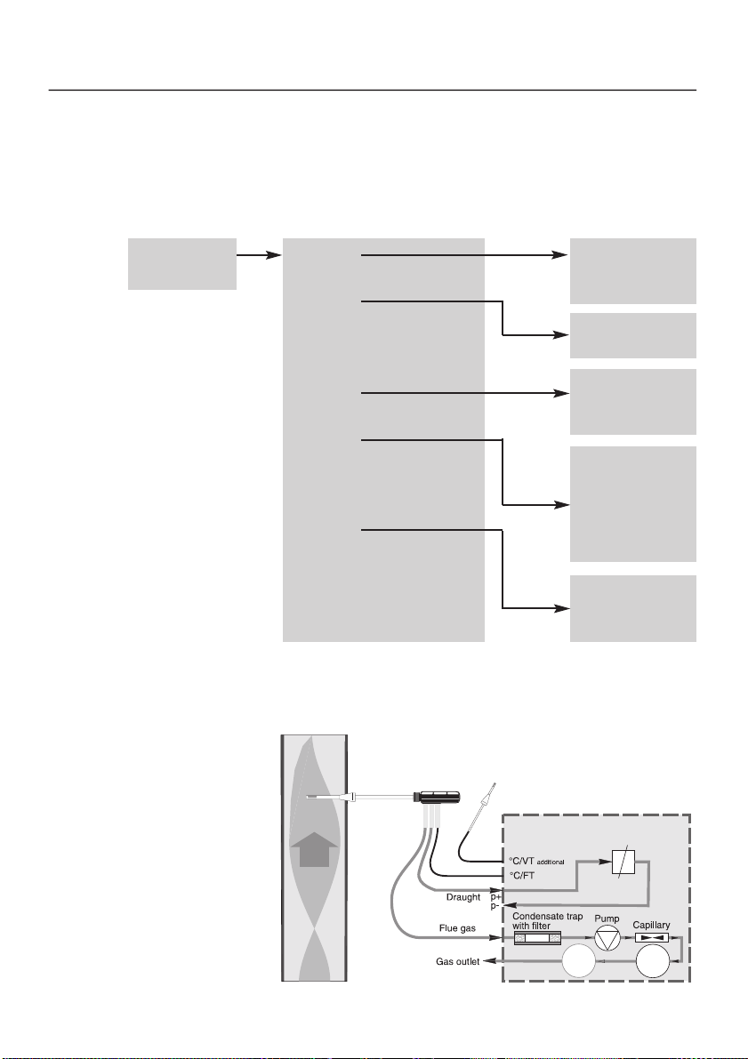
3.3 Menu overview
Measurement
menu Sub-menus
Measurement
view
Main menu
Memory
delta p
delta t
1
memory1
·
·
·
memory20
delta p1
delta p2
View
Fuel
Dat/Clk
Unit
co amb
co undil
1
(testo 325XL only)
3.4 Gas path
RGS
Line 1
·
·
·
Line 12
Nat gas
L oil
H oil
LPG
1
Butane
1
Coal
Pressure
Temperat
Gas
testoter
m
testo 325
p
10
P
CO O
2
➀
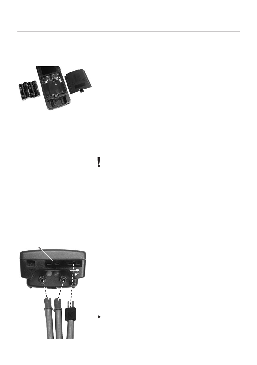
4. Initial operation
4.1 Putting in rechargeable batteries/
batteries
testo 325XL: Insert and connect rechargeable battery pack. No
other steps are necessary.
testo 325M: 4 batteries are included, please insert prior to
initial operation:
1 Remove battery cover at rear of instrument.
2 Insert batteries correctly (+/-).
3 Close cover on battery compartment.
Refer to Chapter 6, Setting up on page 15 for information on
how to set date/time, fuel and measurement units.
4.2 Connecting the mains unit
Operation via mains unit (0554 1084) is also possible if the
rechargeable batteries/batteries are spent. It is normal for the
mains unit to heat up. If the temperature becomes too high
(e.g. due to a defect in the analyser), the mains unit is
protected from overheating by a thermal safety switch.
The rechargeable battery block in testo 325 XL is recharged
in the analyser when it is switched off and is connected to the
mains (battery symbol flashes during recharging, recharging
stops and battery symbol disappears when rechargeable
battery is full). Conventional rechargeable batteries cannot be
recharged in the analyser.
1 Connect plug to analyser.
2 Connect mains plug to mains.
4.3 Connecting sensors/probes
Flue gas probe (accessory)
1 Connect hose for gas (red) to the socket marked by red.
2 Connect hose for pressure (blue) to the pressure+ socket
(blue).
3 Connect flue gas temperature probe pipe to the FT socket.
Ambient air probe (accessory)
Connect ambient air probe pipe to the AT socket ➀.
11
 Loading...