

Page 1
Bedienungsanleitung
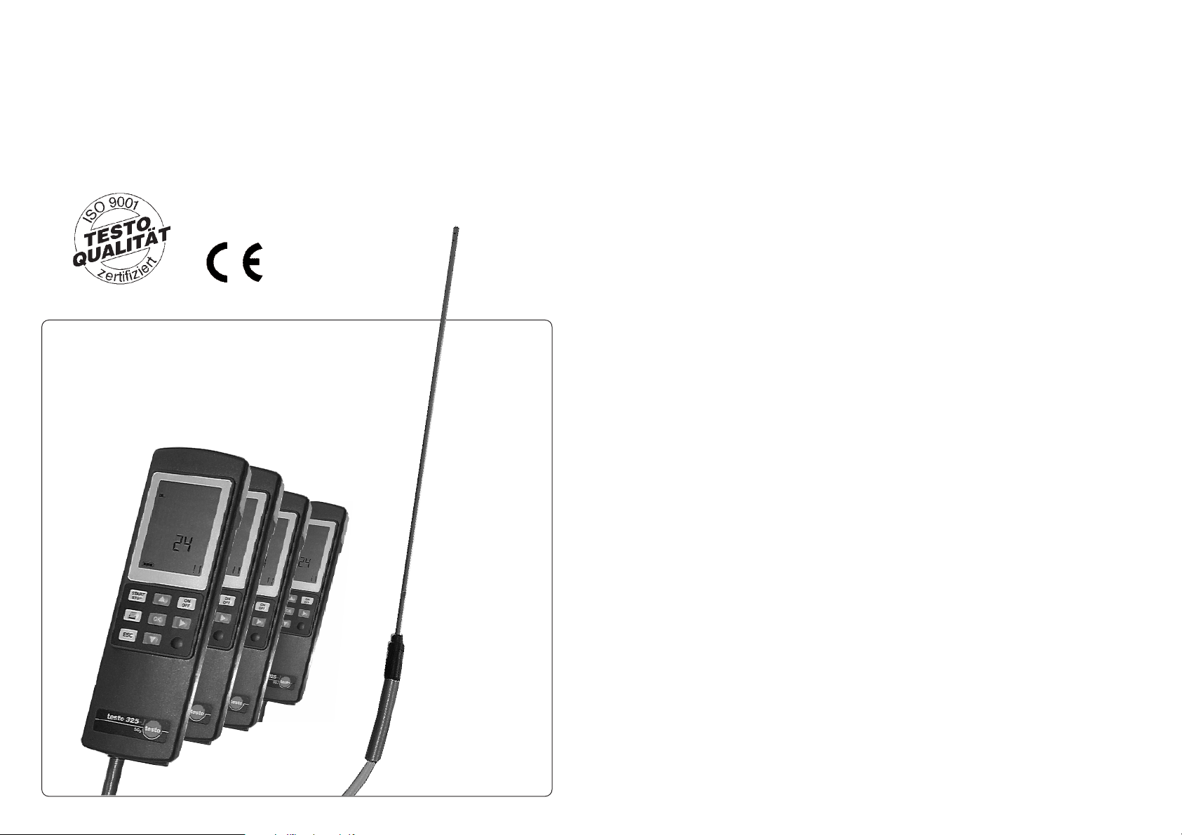
Rauchgas-Analysegerät
testo 325-I
SO2
NO
CO
low
COhigh
Flue Gas Analyser
Instruction manual
Page 2
Betrieb über Steckernetzteil
Für den Betrieb des Gerätes nur das Original-Netzteil verwenden.
Dichtigkeit
Vor jeder Messung muß das komplette Messsystem (Sonde,
Kondensatfalle, Schläuche und Steckanschlüsse) auf Dichtigkeit geprüft werden z. B. durch Aufstecken einer zusammengedrückten Gummiblase auf die Sondenspitze. Durch Ziehen von
Falschluft kann es zu Fehlmessungen kommen.
Gasausgang
Achten Sie bei der Messung darauf, daß der Gasausgang des
Analysegerätes frei liegt, damit das Gas ungehindert entweichen kann. Ist das nicht der Fall, kann dies zu einer
Verfälschung der Messergebnisse führen.
Kondensatfalle
Kondensatfalle spätestens bei Erreichen der Maximal-Linien
entleeren. Die Pumpe muß ausgeschaltet sein (ansonsten
besteht Gefahr für die Messzellen)!
Messzellen
In den Messzellen befindet sich eine geringe Menge konzentrierter Säure bzw. Lauge.Diese Messzellen als Sondermüll
entsorgen.
Messgerät
Das Aufbewahren der Messgeräte in Räumen, in denen
Lösungsmittel gelagert werden, führt zur Zerstörung der
Messzellen.
Warnhinweise
Inbetriebnahme
3
Vorwort.. . . . . . . . . . . . . . . . . . . . . . . . . . . . . . . . . . . . . . . . . . . . . . . . . . . . . . . . . . . . . . . . . . 2
Inbetriebnahme. . . . . . . . . . . . . . . . . . . . . . . . . . . . . . . . . . . . . . . . . . . . . . . . . . . . . . . . . . . . 3
Warnhinweise . . . . . . . . . . . . . . . . . . . . . . . . . . . . . . . . . . . . . . . . . . . . . . . . . . . . . . . . . . . 3
Stromversorgung . . . . . . . . . . . . . . . . . . . . . . . . . . . . . . . . . . . . . . . . . . . . . . . . . . . . . . . . . 4
Gasweg . . . . . . . . . . . . . . . . . . . . . . . . . . . . . . . . . . . . . . . . . . . . . . . . . . . . . . . . . . . . . . . . 4
Geräteabbildung . . . . . . . . . . . . . . . . . . . . . . . . . . . . . . . . . . . . . . . . . . . . . . . . . . . . . . . . . 5
Messbeispiel . . . . . . . . . . . . . . . . . . . . . . . . . . . . . . . . . . . . . . . . . . . . . . . . . . . . . . . . . . . . . . 6
Abgasmessung . . . . . . . . . . . . . . . . . . . . . . . . . . . . . . . . . . . . . . . . . . . . . . . . . . . . . . . . . . 6
Ausdruck der Messergebnisse . . . . . . . . . . . . . . . . . . . . . . . . . . . . . . . . . . . . . . . . . . . . . . 7
Einstellen Datum/Uhrzeit . . . . . . . . . . . . . . . . . . . . . . . . . . . . . . . . . . . . . . . . . . . . . . . . . . . 7
Wartung . . . . . . . . . . . . . . . . . . . . . . . . . . . . . . . . . . . . . . . . . . . . . . . . . . . . . . . . . . . . . . . . . 8
Akku- oder Batteriewechsel. . . . . . . . . . . . . . . . . . . . . . . . . . . . . . . . . . . . . . . . . . . . . . . . . 8
Kondensatfalle. . . . . . . . . . . . . . . . . . . . . . . . . . . . . . . . . . . . . . . . . . . . . . . . . . . . . . . . . . . 8
Filterwechsel . . . . . . . . . . . . . . . . . . . . . . . . . . . . . . . . . . . . . . . . . . . . . . . . . . . . . . . . . . . . 8
Reinigen der Rauchgaspumpe . . . . . . . . . . . . . . . . . . . . . . . . . . . . . . . . . . . . . . . . . . . . . . 9
Messzellenwechsel . . . . . . . . . . . . . . . . . . . . . . . . . . . . . . . . . . . . . . . . . . . . . . . . . . . . . . 10
Fehlermeldungen . . . . . . . . . . . . . . . . . . . . . . . . . . . . . . . . . . . . . . . . . . . . . . . . . . . . . . . . . 13
Zubehör . . . . . . . . . . . . . . . . . . . . . . . . . . . . . . . . . . . . . . . . . . . . . . . . . . . . . . . . . . . . . . . . 14
Testo-Protokolldrucker. . . . . . . . . . . . . . . . . . . . . . . . . . . . . . . . . . . . . . . . . . . . . . . . . . . . 14
Technische Daten. . . . . . . . . . . . . . . . . . . . . . . . . . . . . . . . . . . . . . . . . . . . . . . . . . . . . . . . . 15
Querempfindlichkeiten. . . . . . . . . . . . . . . . . . . . . . . . . . . . . . . . . . . . . . . . . . . . . . . . . . . . 15
Garantiebestimmungen . . . . . . . . . . . . . . . . . . . . . . . . . . . . . . . . . . . . . . . . . . . . . . . . . . . . 16
Bestelldaten . . . . . . . . . . . . . . . . . . . . . . . . . . . . . . . . . . . . . . . . . . . . . . . . . . . . . . . . . . . . . 17
Testo weltweit . . . . . . . . . . . . . . . . . . . . . . . . . . . . . . . . . . . . . . . . . . . . . . . . . . . . . . . . . . . . . .
Liebe Testo-Kundin, lieber Testo-Kunde,
Ihre Entscheidung für den Kauf des testo 325-1 war richtig. Jedes Jahr kaufen tausende Kunden
unsere hochwertigen Produkte. Dafür sprechen mindestens 7 gute Gründe:
1) Bei uns stimmt das Preis-Leistungs-Verhältnis. Zuverlässige Qualität zum fairen Preis.
2) Deutlich verlängerte Garantiezeiten von bis zu 3 Jahren - je nach Gerät!
3) Mit der fachlichen Erfahrung von über 40 Jahren lösen wir Ihre Messaufgabe optimal.
4) Unser hoher Qualitätsanspruch ist bestätigt durch das Zertifikat nach ISO 9001.
5) Selbstverständlich tragen unsere Geräte das von der EU geforderte CE-Zeichen.
6) Kalibrier-Zertifikate für alle relevanten Messgrößen. Seminare, Beratung und Kalibrierung
vor Ort.
7) Auch nach dem Kauf lassen wir Sie „nicht im Regen stehen“.
Unser Service garantiert Ihnen schnelle Hilfe.
Inhalt
Vorwort
2
Meßgerät konform zu EN 61 326-1 Klasse B: 1997, EN 61326-1: 1997
Page 3
Inbetriebnahme
5
Inbetriebnahme
4
Gasweg
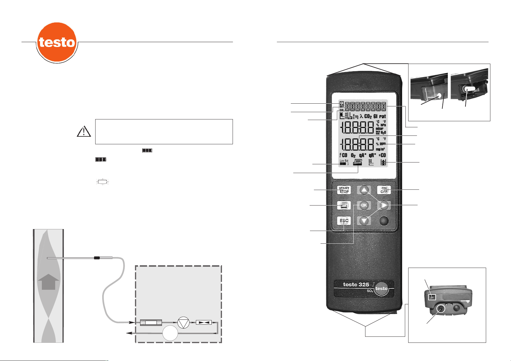
Geräteabbildung
RG = Rauchgas
Gaseingang
Anschluß
Netzteil
Stromversorgung
Standard-Akkus oder Batterien
- Standard-Akkutyp (1.5V IEC KR 15/51 entspr.Typ AA) oder
Batterietyp (1.5V MIGNON Alkaline IEC LR6 •AA• ) verwenden (4 Stück).
Testo-Netzteil (0554.0054)
- Auf guten Kontakt des Anschlußsteckers im testo 325-I
achten.
- Betrieb über Netzteil auch mit leeren Akkus/Batterien möglich.
(Akkus nicht im Gerät ladbar)
Kapazitätsanzeige
Spannung >4,6 V (Standzeit ca. 3 h, bei einer
Umgebungstemperatur von 20°C)
blinkendes Symbol, Spannung <4,6 V
Standzeit Akku ca. 0,5 h
Standzeit Batterie ca. 2,5 h
Sinkt die Akkuspannung unter 4,2 V erfolgt automatische Abschaltung als Schutz gegen Tiefentladung.
Die Erwärmung des Netzteils ist normal. Bei zu hohen
Temperaturen (z. B. durch einen Fehler im Gerät) ist das
Netzteil durch einen Thermoschutzschalter gegen Überhitzung
gesichert.
Uhrzeit
Drucken
Batteriekapazität
Nullungsphase
Pumpe/Messung
ein/aus
Taste Drucken
Der im Display dar-
gestellte Messwert
wird gedruckt.
Abbruch/Zurück
Taste OK
Das Menü zum Ein-
stellen von Datum/
Uhrzeit wird aktiviert.
Datum
Messeinheit
Pumpe aktiv
Ein/Aus-Taste
Blättertasten / Auswahltaste
Mit Pfeiltaste rechts wird im
Menü Datum/Uhrzeit auf die
veränderbaren Parameter zugegriffen. Mit den Tasten auf/
ab Parameter einstellen.
Messwert
CO/NO/
SO2
Messwertbezeichnung
Low Bat
Low Bat
Kondensatfalle
Filter
Auslassöffnung
RG
Gas
Ausgang
testo
325-I
Kondensatfalle
mit Filter
Pumpe
P
Kapillare
Page 4
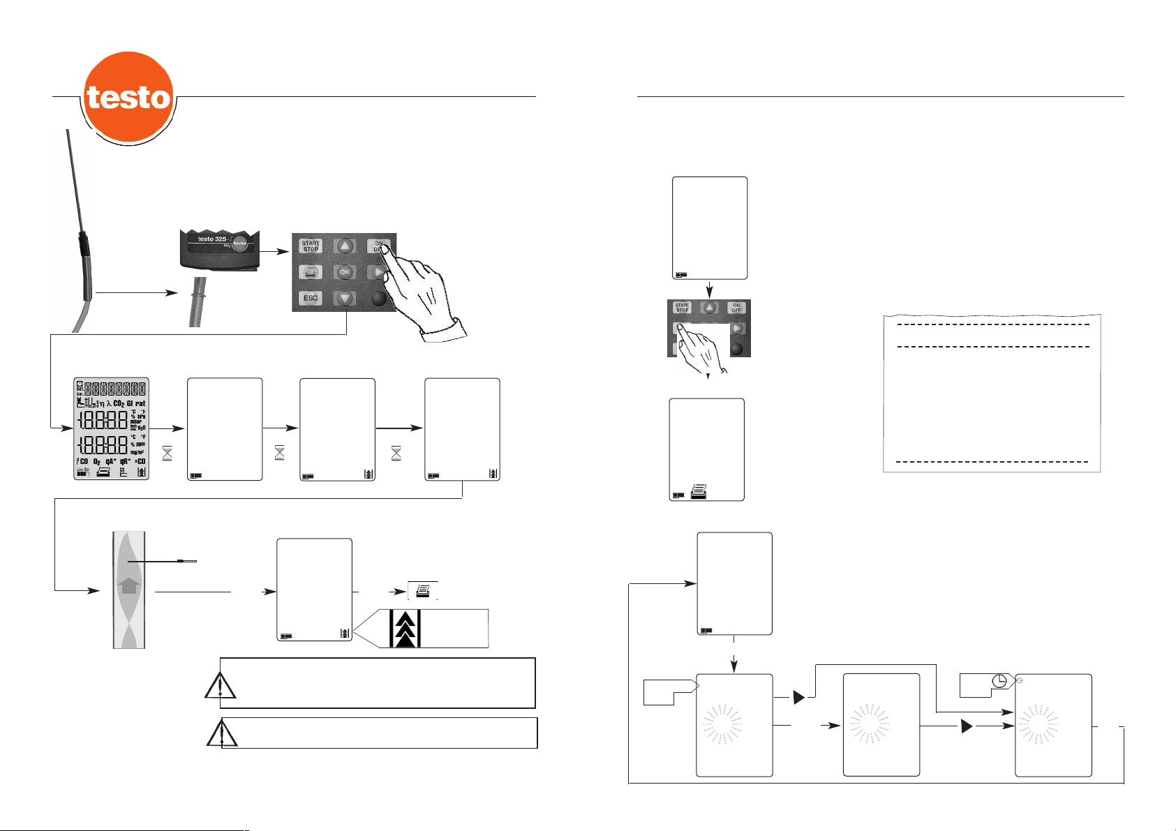
7
Der Messwert wird ausgedruckt mit
- Datum/Uhrzeit
- Messeinheit
(Einstellung Datum/Uhrzeit siehe Referenzteil)
Aus dem Messmenü kann der Ausdruck der Messwerte mit der
Taste Drucken ausgelöst werden. Ausdruck nur bei stehender
Pumpe möglich. Druckvorgang abbrechen mit Taste ESC.
testo 325-I
07.09.1999 10:19:35
SO2 1225 ppm
Datum/Uhrzeit
Meßwert
Meßbeispiel
Ausdruck der Meßergebnisse
6
Messbeispiel
Abgasmessung
Beispiel: testo 325-I SO
2
3 sec.
3 sec.
60 sec.
V 110
6.0
43
START
STOP
START
STOP
ppm
0
SO2
Nach jeder Messung die Messzellen mit Frischluft
spülen (Pumpe Start/Stop) bis der CO-/NO-/SO2-Gehalt
unter 50 ppm.
Bei SO2-Messung auf trockene Gaswege achten!
Sonde
anschließen
Selbsttest
Messmenü
Messmenü
Ausdruck
Pumpe
läuft.
Batterie-Kapazität
Nullungsphase
testo 325-I
einschalten
ppm
225
SO2
Messmenü
ppm
225
SO2
Messmenü
ppm
225
SO2
Messmenü
ppm
225
SO2
CAL.
START
STOP
Mit Taste OK Einstellwert aktivieren.
Mit Taste Rechts Einstellfeld wechseln.
Mit Taste Oben Wert erhöhen, mit Taste Unten Wert verringern.
Mit Taste OK Einstellungen bestätigen und Sprung ins
Meßmenü.
Mit Taste ESC zurück ins Hauptmenü, keine Übernahme der
Einstellungen.
15.03
1999
03.15
1999
14:15
Einstellfeld
blinkt
Umschalten
auf
US-Format
Symbol
Uhrzeit
Symbol
Datum
Einstellen Datum/Uhrzeit
OK
OK
DDAATT
DAT
RG
Page 5
9
Kondensatfalle
Filterwechsel
Bei optisch erkennbarer Verschmutzung des Filters muß dieser
ausgetauscht werden.
Dazu die Kondensatfalle entriegeln und vom Gehäuse entfernen.
Filter herausziehen und durch neuen ersetzen. Ersatzfilter
(Best.-Nr. 0554.0040, 10er Pack) bestellen.
Ausschließlich diesen Filter verwenden.
Nach jedem Filterwechsel Dichtigkeitstest durchführen (siehe
Seite 3).
Füllstandanzeige der Kondensatfalle nicht überschreiten.
Zum Entleeren der Kondensatfalle Entleerungs-Stopfen herausziehen.
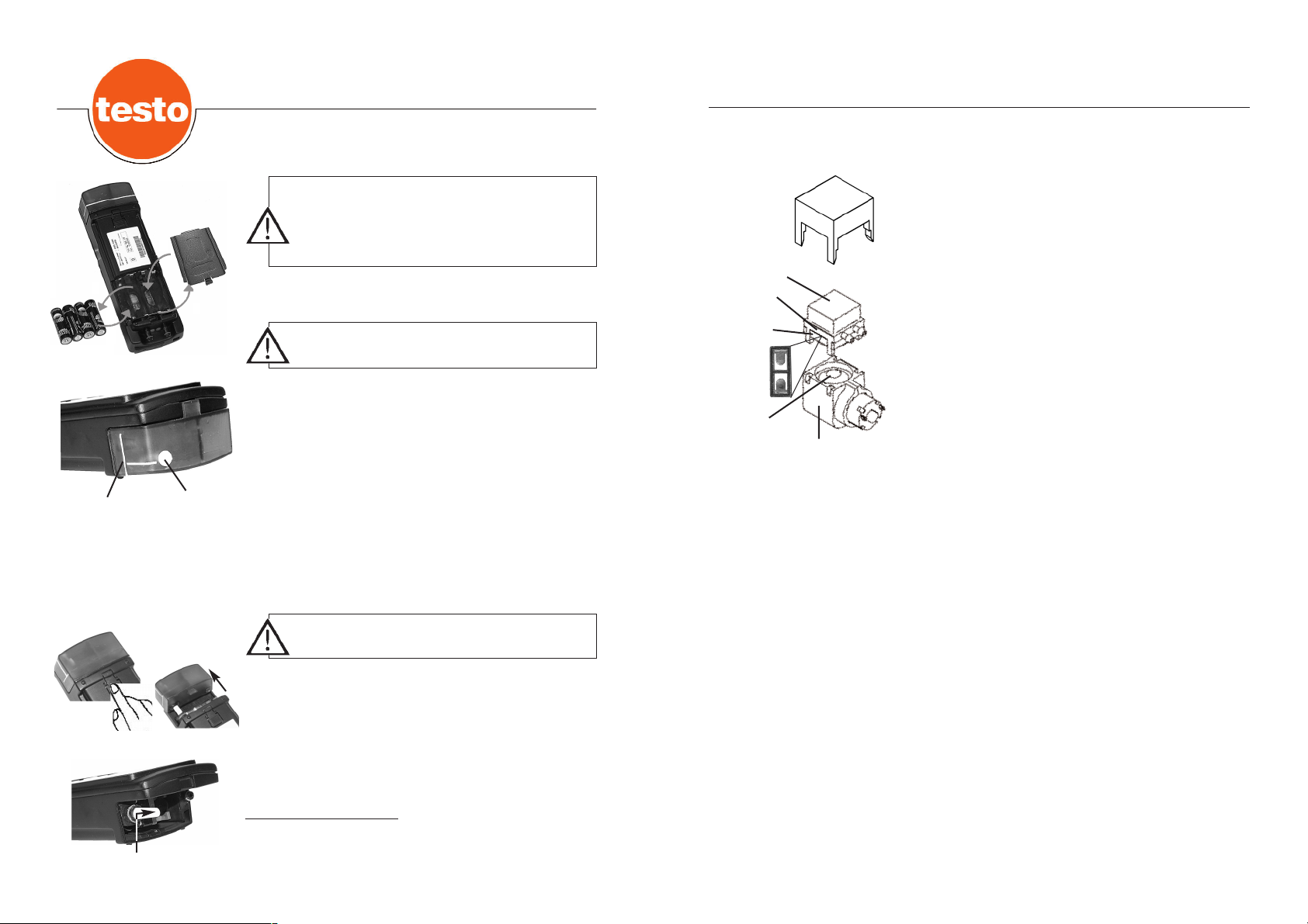
Leere/defekte Akkus bzw. leere Batterien aus dem Batteriefach
entnehmen und durch neue Akkus oder Batterien ersetzen.
Achtung!
Auf richtige Polarität der Akkus oder
der Batterien achten!
Vor Akku- oder Batteriewechsel das Gerät ausschalten.
Den Wechsel innerhalb von 1 - 2 Minuten durchführen
oder Netzteil einstecken.
Ansonsten droht der Ver-
lust der eingestellten Werte Datum/Uhrzeit.
Vor dem Filterwechsel
Kondensatfalle entleeren.
8
Wartung
Wartung
Akku- oder Batteriewechsel
Reinigen der Rauchgaspumpe
Filter
Füllstandanzeige
Kondensatentleerung
1
2
3
4
max
m
a
x
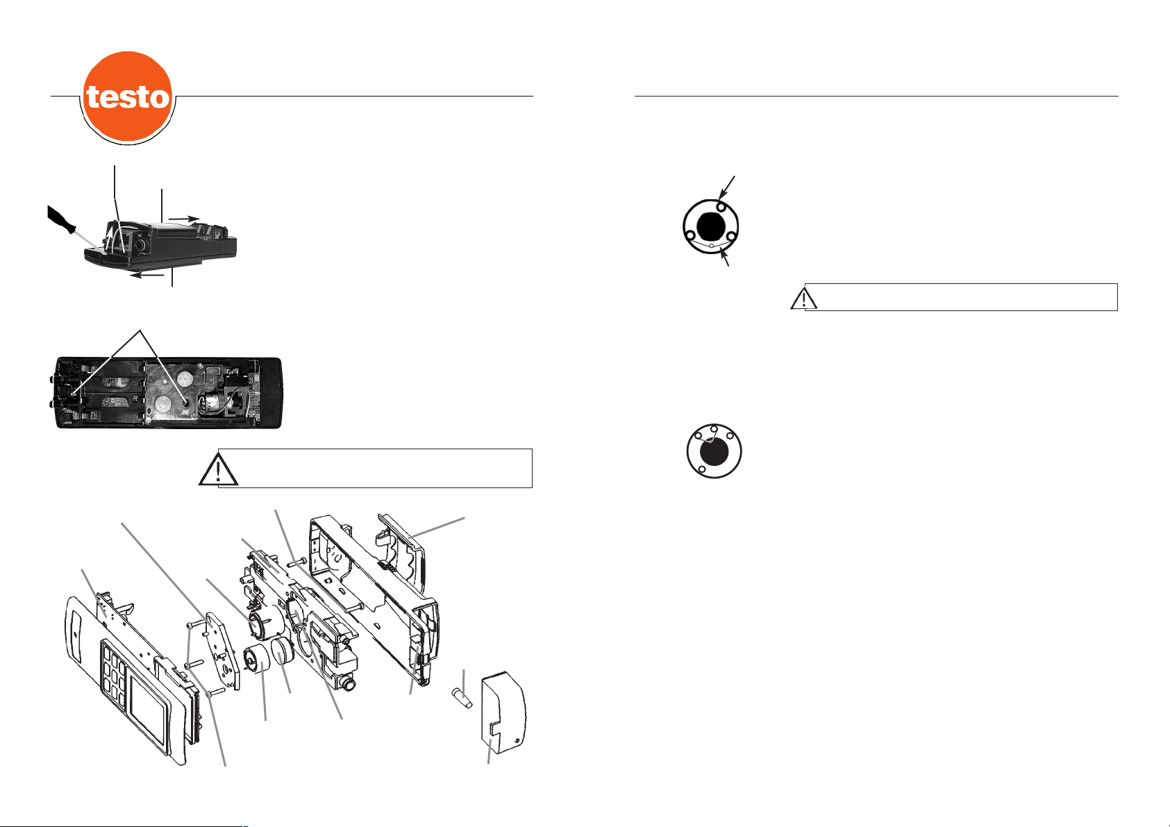
Gehäuse des Messgeräts öffnen (siehe Seite 10, Punkte 1 -8).
- Vorsichtig die Pumpe herausziehen.
- Werkzeug ”Pump Tool” in die Führungen des Pumpenkopfs
stecken.
- Werkzeug ”Pump Tool” mit dem Pumpenkopf abnehmen.
- Membranaufnehmer vom Pumpenkopf entfernen und
Membrane entnehmen.
- Pumpenmembrane, Pumpenteller und Pumpenkopf mit
Spiritus oder Wasser reinigen.
- Pumpenmembrane in den Membranaufnehmer einlegen und
in den Pumpenkopf einfügen
- Pumpenkopf auf die Pumpe aufsetzen.
- Werkzeug ”Pump Tool” entfernen.
- Pumpe in den Montageblock einsetzen.
- Messgerät zusammensetzen (siehe Seite 11).
PUMP
TOOL
Pumpe
(Art.-Nr.
0239.0015)
Pumpenteller
Pumpenkopf
Pump Tool
Pump Tool
(Art.-Nr.
0192.0468)
Membrane
(Art.-Nr.
0193.0072)
Membranaufnehmer
Page 6
11
10
Wechsel der COlow-Messzelle
Vor Einbau der neuen COlow-Messzelle die Kurzschlussfeder vorsichtig von den Kontakten entfernen.
- Messzelle vom Messkammer-Deckel abziehen und neue
Messzelle aufstecken.
Kurzschlußfeder
COlow-Meßzelle
Wechsel der SO2-, NO-, COhigh-Messzelle
- Die Messzelle befindet sich in der Messkammer. Messzelle
entnehmen und neue Messzelle einsetzen. Beim Einbau auf
die Führungen an Messzelle und Messkammer achten.
- Vor Einbau der neuen SO2-,NO-COhigh-Zellen die Kurz-
schlussfeder vorsichtig von den Kontakten entfernen.
Zusammenbau des testo 325-I
- Messkammer-Deckel auf die Messkammer legen. Die Befestigungsschrauben (3 Stück) anziehen.
- Montageblock mit der Elektronik zusammenfügen.
- Montageblock und Elektronik in das Gehäuseoberteil legen.
- Befestigen des Montageblocks und der Elektronik an das
Gehäuseoberteil mit den Halterungsschrauben (2Stück).
- Gehäuseunterteil aufsetzen und in entgegengesetzter Pfeilrichtung schließen.
Achtung: Flex-Leitung der Tastatur nicht einklemmen!
- Fixierplatte einsetzen und Filter einstecken.
- Kondsatfalle aufsetzen.Auf Einrastton achten.
- Batterien/Akkus einlegen und mit Batteriefach-Deckel
schließen.
- NO-Filter aus der Messkammer herausnehmen. Beim Einlegen des neuen Filters darauf achten, daß die Fläche mit
den Bohrungen nach unten in der Meßkammer liegt.
Wartung
COlow-Messzellenwechsel
Bei Wechsel einer COlow-Messzelle muß auch der NO-Filter
erneuert werden.
Vor Berühren der Elektronik elektrische Ladung des eigenen
Körpers abbauen.
Berührungen der Elektronik vermeiden.
Batteriefach-Deckel
Kondensatfalle
Fixierplatte
Meßkammer
CO lowMeßzelle
Befestigungsschrauben
NO-Filter
Filter
Montageblock
SO2-, NO-,
CO
high-
Meßzelle
Meßkammer-Deckel
Platine
Halterungsschrauben
1.) Schlauchverbinder der Rauchgassonde, sowie das Netzteil
vom testo 325-I abziehen.
2.) Kondensatfalle vor dem Abziehen entleeren.
3.) Kondensatfalle entriegeln und vom Gehäuse entfernen
4.) Filtereinsatz herausnehmen (siehe Seite 8).
5.) Fixierplatte mit einem Schraubendreher entfernen.
6.) Batteriefach öffnen und Batterien/Akkus entnehmen
(siehe Seite 8).
7.) Das Gehäuse des testo 325-I wird durch Bewegen
der Gehäuseteile in Pfeilrichtung geöffnet (siehe
Skizze).
8.) Gehäuseunterteil abnehmen.
9.) Halterungsschrauben lösen (siehe Skizze).
10.) Montageblock mit der Elektronik aus dem
Gehäuseoberteil herausnehmen (siehe
unten).
11.) Montageblock von der Platine abziehen.
12.) Befestigungsschrauben (3 Stück) des Mess-
kammer-Deckels lösen. Deckel entfernen.
Fixierplatte
Gehäuseunterteil
Gehäuseoberteil
Halterungsschrauben
Wartung
Messzellenwechsel
Page 7

13
Fehlermeldung
Fehlermeldungen während des Meßbetriebs
blinkt
Während der Nullungsphase
SO2 D blinkt
NO D blinkt
COlow D blinkt
COhigh D blinkt
Vor dem Ausschalten
SO2 blinkt
NO blinkt
COlow blinkt
COhigh blinkt
Nach dem Einschalten/Nullungdphase
SO2 A blinkt
NO A blinkt
COlow A blinkt
COhigh A blinkt
12
Fehlermeldungen
Ursache / Behebung
Zulässige Betriebstemperatur über- oder unterschritten. Die Umgebungstemperatur ändert sich
auf nicht zulässige Werte. Umgebungstemperatur anpassen.
Messung des Nullpunkts nicht stabil. Mehrmaliges Durchlaufen der Nullungsphase abwarten.
Bringt dies kein Erfolg ist die Messzelle verbraucht.
Im Gerät befindet sich noch Rauchgas oder bei
letzter Messung wurden sehr hohe Konzentrationen gemessen oder Nullungsphase verlängert
sich.
Ursache: Nach letzter Messung nicht genügend
mit Frischluft gespült oder Sonde befindet sich
im Rauchgas.
→ Sonde an Frischluft bringen. Wenn nach
mehrmaligem Durchlaufen der Nullungsphase
keine Änderung eintritt, liegt ein Zellendefekt
vor oder die Zelle ist verbraucht.
Geräteversorgungsspannung wird zu niedrig.
Akku laden/Batterie wechseln oder Netzteil
anschließen.
Im Gerät befindet sich noch Rauchgas oder bei
letzter Messung wurden sehr hohe Konzentrationen gemessen oder Nullungsphase verlängert
sich.
Ursache: Nach letzter Messung nicht genügend
mit Frischluft gespült oder Sonde befindet sich
im Rauchgas.
→ Sonde an Frischluft bringen. Wenn nach
mehrmaligem Durchlaufen der Nullungsphase
keine Änderung eintritt, liegt ein Zellendefekt
vor oder die Zelle ist verbraucht.
LOW BAT
Eingabe SO2-, NO-, CO-Zellenkoeffizent
Der Zellenkoeffizient befindet sich auf dem Beipackzettel der
entsprechenden Ersatz-Messzelle.
Nach Eingabe der Koeffizienten und Bestätigen mit Taste OK
erfolgt Sprung in die Nullungsphase.
Während der Kalibrierphase kann jederzeit nach zweimaligem
Betätigen der Taste ESC in die Nullungsphase gesprungen
werden.
Taste Drucken und Taste Rechts innerhalb 3 Sekunden
während der Kapazitätsanzeige gleichzeitig gedrückt halten.
Nachkalibrierung über die Testo ServiceStellen, Tochtergesellschaften und
Vertretungen.
SO2
°C
25.50
25.8
Zahlenstelle
auswählen
Zahlenwert
erhöhen
Zahlenwert
verringern
3 sec.
<3 sec.
Taste Drucken und
Taste Rechts
gleichzeitig drücken
Hauptmenü
Batterie-
Kapazität
Bei Abbruch der Kalibrierphase
falsche Messwerte!
V 110
6.0
43
CAL.
CAL.
OK
Messmenü
ppm
0
SO2
60 sec.
Nullungsphase
Wartung
Messzellenwechsel
Page 8

15
testo 325-I
Allgemeine technische Daten
Max. Unterdruck im Abgas: 50 hPa
Gewicht: 500g
Abmessungen: 216 x 68 x 47 mm
Transport-/
Lagertemperatur: -20...+50 °C
Umgebungstemp.: +4...+45 °C
Stromversorgung: über Stecker-Netzteil, Batterien
oder austauschbare Akkus
Batteriestandzeit: > 4 h
Gehäusematerial: ABS
Abgassonde
Entnahmerohr: Länge 300 mm, Ø 6 mm
Einsatztemperatur: max. + 500 °C
Schlauchlänge: 3 m (Tygon-Material bei
SO2-Version)
Technische Daten
14
testo 325-I testo 325-I testo 325-I testo 325-I
SO2 NO CO low CO high
Messbereich 0...3000 ppm 0...1000 ppm 0...2000 ppm 20...40.000 ppm
Genauigkeit bis 400 ppm bis 400 ppm bis 400 ppm bis 800 ppm
< 20 ppm < 20 ppm < 20 ppm < 40 ppm
bis 2000 ppm
± 5% v.Mw.
> 400 ppm > 200 ppm > 400 ppm >2000 ppm
< 5% v.Mw. < 5% v.Mw. < 5% v.Mw. < 10% v.Mw.
Einstellzeit t90 < 80 s < 60 s < 60 s < 70 s
Auflösung 1 ppm 1 ppm 1 ppm 5 ppm
ab 10.000 ppm
0.001 Vol.%
Technische Daten
Druckerart: . . . . . . .infrarotgesteuerter Thermodrucker
Betriebstemperatur: . . . . . . . . . . . . . . . . . . .0...+50 °C
Lager-/Transporttemp.: . . . . . . . . . . . . . . .-40....+60 °C
Abmessungen: . . . . . . . . . . . . . . . . .150 x 88 x 50 mm
Gewicht: . . . . . . . . . . . . . . . . . .0,33 kg (inkl. Batterien)
Stromversorgung: . . . . . . . . .4 Mignon-Batterien 1,5 V
oder NC-Akkus
Zubehör: . . . . . . . . . .Ersatzpapier Best.Nr. 0554.0569
- Papiervorschub
- Zurück aus Ruhemodus
- Selbsttest = Taste beim
Einschalten gedrückt halten
Übertragungsstrecke:
Magnetplatte auf der
Geräte-Rückseite
Achtung: Nach etwa 10-minütiger Inaktivität schaltet
der Drucker in einen Ruhemodus.
Entsorgungshinweis:
Entladene Batterien in Sammelbox werfen.
Um Kurzschlüssen vorzubeugen, Batterien
einzeln in Plastikbeutel geben.
60°
60°
max. 2 m
10°
20°
Kontrast einstellen
EIN/AUS
ï
bedruckbare Seite
Datenempfang und
Einschalt-Kontrolllampe
grün = EIN/Batterie o.k.
gelb = EIN/Batteriewarnung
rot = EIN/Batterie leer
ï
ï
ï
Fenster nicht verschmutzen!
I
0
Testo-Protokolldrucker 0554.0545
Zubehör
Querempfindlichkeiten
Quergas
Modul CO NO SO2 NO2 H2S H2 CI2 HCI HCN CO2
CO ---000000000
NO 0 --- 0 <5% 0 0 0 <5% 0 0
SO2 <3% 0 --- -110% 0 <3% -80% 0 30% 0
20°
20°
10°
30°
Page 9

16
17
testo 325-I
Bestelldaten
Beschreibung
Bestell-Nr.
Gerät
Abgas-Analysegerät testo 325-I (SO2) inkl. Batterien 0632.3260
Abgas-Analysegerät testo 325-I (NO) inkl. Batterien 0632.3261
Abgas-Analysegerät testo 325-I (COlow) inkl. Batterien 0632.3262
Abgas-Analysegerät testo 325-I (COhigh) inkl. Batterien 0632.3263
Abgas-Sonden
Abgas-Sonde (Länge 300 mm, Tmax +500 °C, SO2) 0600.7541
Abgas-Sonde 0600.7542
Konus für Abgas-Sonde 0554.9050
Abgas-Sonde (Länge 700 mm, Tmax +1000 °C) inkl. Spezialschlauch
für SO2-Messungen 0699.3451/3
Drucker
Testo-Protokolldrucker 0554.0545
Zubehör
Geräte SoftCase (zur Befestigung am Kessel) 0516.2570
Gerätekoffer (Kunststoffausführung) 0516.3250
Netzteil (230 V für Netzbetrieb) 0554.1084
Netzteil GB 0554.0041
Netzteil J 0554.0052
Netzteil USA 0554.0053
Ersatz-Schmutzfilter für testo 325-I (10 Stück) 0554.0040
Ersatz-Papier für Protokolldrucker 0554.0569
Ersatzzellen
COlow-Ersatzzelle inkl. Filter 0390.0168
COhigh-Ersatzzelle 0390.0142
SO2-Ersatzzelle 0390.0143
NO-Ersatzzelle 0390.0144
Garantiebestimmungen
Gerät: 24 Monate
Entnahmesonde: 12 Monate
Zubehör 6 Monate
Messzellen 6 Monate
Drucker 12 Monate (außer Druckwerk)
Sehr geehrte Kundin, sehr geehrter Kunde,
vielen Dank für das Vertrauen, das Sie Testo mit dem Kauf dieses Meßgerätes entgegengebracht haben. Sie haben eine gute
Wahl getroffen. Sollten Sie trotzdem Grund zur Beanstandung
unseres Produktes haben, beheben wir Mängel kostenlos, die
nachweislich auf einen Werksfehler beruhen. Voraussetzung ist,
daß Sie diesen Mangel unverzüglich nach Feststellung und
innerhalb der von uns gewährten Garantiezeit melden.
Natürlich sind Verschleißteile wie zum Beispiel Akkus, Meßzellen, Filter, Meßelemente usw. sowie leicht zerbrechliche Teile
von dieser Garantie ausgenommen. Ebenso Schäden, die
durch nicht bestimmungsgemäßen Gebrauch sowie infolge von
Nichtbeachtung der Bedienungsanleitung entstanden sind.
Die Garantie entfällt außerdem, wenn das Meßgerät geöffnet
wurde - soweit dies nicht ausdrücklich in der Bedienungsanleitung zu Wartungszwecken beschrieben ist - oder aber Seriennummern im Gerät verändert, beschädigt oder entfernt wurden.
Die Garantiezeit beträgt für Handgeräte 24 Monate, für Fühler
12 Monate. Wenn nicht anders definiert, gelten für Zubehörteile
6 Monate. Garantieleistungen bewirken keine Verlängerung der
Garantiefrist.
Wurden neben der Garantieleistung notwendige Reparaturen,
Justagen oder dergleichen durchgeführt, sind die Garantieleistungen kostenlos, die anderen Leistungen werden aber
ebenso wie Transport und Verpackung berechnet.
Weitergehende oder andere Ansprüche, insbesondere bei entstandenen Schäden die nicht das Gerät betreffen, sind - soweit
eine Haftung nicht zwingend gesetzlich vorgeschrieben ist ausgeschlossen.
Leistungen nach der Garantiezeit
Selbstverständlich sind wir auch nach Ablauf der Garantiezeit
für Sie da. Bei Funktionsstörungen senden Sie uns Ihr Meßgerät mit einer kurzen Fehlerbeschreibung. Geben Sie bitte
auch Ihre Telefonnummer für eventuelle Rückfragen an.
Bei uns wird KUNDENDIENST groß geschrieben.
Garantie
Page 10

Instruction manual
Flue Gas Analyser
testo 325-I
SO2
NO
CO
low
COhigh
Page 11

Operation via power unit
Only use the original power unit for operating the instrument.
Integrity
Before each measurement the complete measuring system
(probe, condensate trap, hoses and plug connections) must be
checked for integrity, e.g. by attaching a compressed rubber
bladder to the tip of the probe. If secondary air is drawn in,
measuring errors may result.
Gas output
During measurement, ensure that the gas output of the
analyser is open, so that the gas can escape unimpeded. If
this is not the case, falsification of the measuring results may
occur.
Condensate trap
Empty the condensate trap when the maximum mark is
reached, at the latest. The pump must be switched off
(otherwise the measuring cells are at risk)!
Measuring cells
The measuring cells contain a small quantity of concentrated
acid or lye, and should be disposed of as special waste.
Measuring instrument
Keeping the measuring instruments in rooms in which solvents
are stored will result in damage to the measuring cells.
Warning notes
Initial operation
3
Measuring instrument conform with EN 61 326-1 Class B: 1997, EN 61 326-1: 1997
Introduction. . . . . . . . . . . . . . . . . . . . . . . . . . . . . . . . . . . . . . . . . . . . . . . . . . . . . . . . . . . . . . . 2
Initial operation. . . . . . . . . . . . . . . . . . . . . . . . . . . . . . . . . . . . . . . . . . . . . . . . . . . . . . . . . . . . 3
Warning notes . . . . . . . . . . . . . . . . . . . . . . . . . . . . . . . . . . . . . . . . . . . . . . . . . . . . . . . . . . . 3
Power supply . . . . . . . . . . . . . . . . . . . . . . . . . . . . . . . . . . . . . . . . . . . . . . . . . . . . . . . . . . . . 4
Gas path . . . . . . . . . . . . . . . . . . . . . . . . . . . . . . . . . . . . . . . . . . . . . . . . . . . . . . . . . . . . . . . 4
Instrument diagram . . . . . . . . . . . . . . . . . . . . . . . . . . . . . . . . . . . . . . . . . . . . . . . . . . . . . . . 5
Measurement example . . . . . . . . . . . . . . . . . . . . . . . . . . . . . . . . . . . . . . . . . . . . . . . . . . . . . . 6
Flue gas measurement . . . . . . . . . . . . . . . . . . . . . . . . . . . . . . . . . . . . . . . . . . . . . . . . . . . . 6
Printout of measured results . . . . . . . . . . . . . . . . . . . . . . . . . . . . . . . . . . . . . . . . . . . . . . . . 7
Setting the date/time . . . . . . . . . . . . . . . . . . . . . . . . . . . . . . . . . . . . . . . . . . . . . . . . . . . . . . 7
Maintenance . . . . . . . . . . . . . . . . . . . . . . . . . . . . . . . . . . . . . . . . . . . . . . . . . . . . . . . . . . . . . . 8
Changing rechargeable battery or battery . . . . . . . . . . . . . . . . . . . . . . . . . . . . . . . . . . . . . . 8
Condensate trap . . . . . . . . . . . . . . . . . . . . . . . . . . . . . . . . . . . . . . . . . . . . . . . . . . . . . . . . . 8
Changing the filter . . . . . . . . . . . . . . . . . . . . . . . . . . . . . . . . . . . . . . . . . . . . . . . . . . . . . . . . 8
Cleaning the flue gas pump. . . . . . . . . . . . . . . . . . . . . . . . . . . . . . . . . . . . . . . . . . . . . . . . . 9
Changing the measuring cells . . . . . . . . . . . . . . . . . . . . . . . . . . . . . . . . . . . . . . . . . . . . . . 10
Error messages. . . . . . . . . . . . . . . . . . . . . . . . . . . . . . . . . . . . . . . . . . . . . . . . . . . . . . . . . . . 13
Accessories. . . . . . . . . . . . . . . . . . . . . . . . . . . . . . . . . . . . . . . . . . . . . . . . . . . . . . . . . . . . . . 14
Testo printer . . . . . . . . . . . . . . . . . . . . . . . . . . . . . . . . . . . . . . . . . . . . . . . . . . . . . . . . . . . . 14
Technical data. . . . . . . . . . . . . . . . . . . . . . . . . . . . . . . . . . . . . . . . . . . . . . . . . . . . . . . . . . . . 15
Cross sensitivities . . . . . . . . . . . . . . . . . . . . . . . . . . . . . . . . . . . . . . . . . . . . . . . . . . . . . . . 15
Warranty conditions. . . . . . . . . . . . . . . . . . . . . . . . . . . . . . . . . . . . . . . . . . . . . . . . . . . . . . . 16
Ordering data . . . . . . . . . . . . . . . . . . . . . . . . . . . . . . . . . . . . . . . . . . . . . . . . . . . . . . . . . . . . 17
Testo worldwide . . . . . . . . . . . . . . . . . . . . . . . . . . . . . . . . . . . . . . . . . . . . . . . . . . . . . . . . . . . .
Dear Testo Customer,
You have made the right decision in purchasing the testo 325-1. Every year thousands of
customers purchase our high quality products. There are at least 7 good reasons for this:
1) We have achieved the right price/performance ratio. Reliable quality at a fair price.
2) Considerably extended warranty periods of up to 3 years -depending on the instrument!
3) With specialist experience of over 40 years, we can provide the optimum solution for your
measuring task.
4) Our high quality standards are confirmed by certification in accordance with ISO 9001.
5) Naturally our instruments bear the CE mark required by the EU .
6) Calibration certificates for all relevant measurement quantities.Seminars, consultation and
calibration on site.
7) And even after purchase, we won’t leave you in the lurch.
Our service guarantees rapid assistance.
Contents
Introduction
2
Page 12

Initial operation
5
Instrument diagram
Gas input
Power unit
connection
Time
Printer
Battery capacity
Zeroing phase
Pump/Measurement
on/off
Print button
The measured value
shown in the display
is printed.
Cancel/Back
OK button
The menu for setting
the date and time is
activated.
Date
Measurement unit
Pump active
On/off button
Scroll buttons / selection button
With the right arrow button
you can access the variable
parameters in the date/time
menu. Set the parameters with
the up/down buttons.
Measured value
Measured value designation
Condensate trap
Filter
Outlet
opening
Initial operation
4
Gas path
Power supply
Standard rechargeable batteries or batteries
- Use standard rechargeable battery type (1.5V IEC KR 15/51
in accordance with type AA) or battery type (1.5V round cell,
Testo power unit (0554.0054)
- Ensure good contact of the connection plug in the testo 325-I.
- Operation possible via power unit even with empty
rechargeable batteries/batteries.
(Accumulators cannot be charged in the device)
Capacity display
Voltage >4.6 V (service life approx. 3 h, at an
ambient temperature of 20°C)
flashing symbol, voltage <4.6 V
Rechargeable battery service life approx. 0.5 h
Battery service life approx. 2.5 h
If the rechargeable battery voltage falls below 4.2 V,
switch off occurs automatically in order to protect
against total discharge.
It is normal for the power unit to heat up. In the event of
excessively high temperatures (e.g.due to a fault in the
instrument) the power unit is protected against overheating
by a thermal protection switch.
CO/NO/
SO2
Low Bat
Low Bat
RG = Flue gas
Condensate trap
with filter
Pump
Capillary
Output
Gas
RG
Gas
Ausgang
testo
325-I
Kondensatfalle
mit Filter
Pumpe
P
Kapillare
Page 13

7
The measured value is printed out with
- Date/time
- Unit of measurement
(For date/time setting, see reference unit)
From the measuring menu, printout of the measured values can
be triggered with the Print button. Printout is only possible
when the pump is stationary. Cancel the printing procedure with
the ESC button.
testo 325-I
07.09.1999 10:19:35
SO2 1225 ppm
Date/time
Measured value
Measurement example
Printout of measured results
START
STOP
Measuring menu
ppm
225
SO2
Measuring menu
ppm
225
SO2
Measuring menu
ppm
225
SO2
Activate the set-point with the OK button.
Change the setting field with the right button.
Increase the value with the up button, decrease the value with
the down button.
The OK button confirms the settings and takes you to the
measuring menu.
The ESC button takes you back to the main menu, without
adopting the settings.
15.03
1999
03.15
1999
14:15
Setting field
flashes
Change
over to
US format
Time
symbol
Date
symbol
Setting the date/time
OK
OK
DDAATT
DAT
6
Measurement example
Flue gas measurement
Example: testo 325-I SO
2
3 sec.
3 sec.
60 sec.
V 110
6.0
43
START
STOP
ppm
0
SO2
Flush the measuring cells with fresh air after each
measurement (pump start/stop) until the CO/NO/SO
2
content is below 50 ppm.
Ensure that gas paths are dry when measuring SO2.
Connect
probe
Self-test
Measuring menu
Measuring menu
Printout
Pump
running.
Battery capacity
Zeroing phase
Switch on
testo 325-I
ppm
225
SO2
CAL.
START
STOP
RG
Page 14

9
Maintenance
Cleaning the flue gas pump
Open the housing of the measuring instrument (see page 10,
points 1-8).
- Carefully remove the pump.
- Place the pump tool into the guides of the pump head.
- Remove the pump tool with the pump head.
- Remove the diaphragm holder from the pump head and
remove the diaphragm.
- Clean pump diaphragm, pump plate and pump head with
spirit or water.
- Insert pump diaphragm into the diaphragm mounting and
introduce into the pump head.
- Attach pump head to the pump.
- Remove pump tool.
- Fit pump into the mounting block.
- Assemble measuring instrument (see page 11).
PUMP
TOOL
Pump
(Part no.
0239.0015)
Pump plate
Pump head
Pump tool
Pump tool
(Part no.
0192.0468)
Diaphragm
(Part no.
0193.0072)
Diaphragm
holder
Condensate trap
Changing the filter
In the event of visually detectable contamination of the filter, the
filter must be replaced.
To do this, unlock the condensate trap and remove from the
housing.
Remove the filter and replace with a new one. Order a
replacement filter (Part no. 0554.0040, pack of 10).
Only use this filter.
Perform an integrity check after each filter change (see
page 3).
Do not exceed level indicator of condensate trap.
To empty the condensate trap, remove the drain plug.
Remove dead/defective rechargeable batteries or dead
batteries from the battery compartment and replace with new
rechargeable batteries or batteries.
Caution!
Observe correct polarity of rechargeable batteries or
batteries!
Switch off the instrument before changing the
rechargeable battery or battery.
Perform change within 1 - 2 minutes or insert power
unit.
Otherwise there is a risk of losing the set date/time
values.
Before changing the filter
empty the condensate trap.
8
Maintenance
Changing rechargeable battery or battery
Filter
Level
indicator
Condensate
drain
1
2
3
4
max
m
a
x
Page 15

11
Changing the COlow measuring cell
Before fitting the new COlow measuring cell, carefully
remove the short-circuit springs from the contacts.
- Remove measuring cell from the measuring chamber cover
and attach new measuring cell.
Short-circuit
spring
COlow measuring cell
Changing the SO2,NO,COhigh measuring cell
- The measuring cell is located in the measuring chamber.
Remove measuring cell and insert new measuring cell. When
fitting, observe the guides on the measuring cell and the
measuring chamber.
- Before fitting the new SO2,NO/COhigh cells, remove the
short-circuit springs carefully from the contacts.
Assembling the testo 325-I
- Place measuring chamber cover on the measuring chamber.
Tighten the fastening screws (3 pieces).
- Connect mounting block to the electronics.
- Place mounting block and electronics in the top section of the
housing.
- Fix the mounting block and the electronics to the top section
of the housing with the mounting screws (2 pieces).
- Attach bottom section of housing and close in the opposite
direction to the arrow.
Note: Do not let keypad ribbon cable get caught.
- Fit fixing plate and insert filter.
- Attach condensate trap. Listen for the engagement tone.
- Insert batteries/rechargeable batteries and close with battery
compartment cover.
- Remove NO filter from the measuring chamber.When
inserting the new filter, ensure that the surface with the
boreholes is positioned downwards in the measuring
chamber.
Maintenance
Changing the COlow measuring cell
When a COlow-measuring cell is changed, the NO-filter
must also be replaced.
10
Before touching the electronics, discharge any static
electricity from your own body.
Avoid touching the electronics.
Battery compartment
cover
Condensate trap
Fixing plate
Measuring
chamber
CO low
measuring cell
Fastening screws
NO filter
Filter
Mounting block
SO2
, NO,
CO
high
measuring cell
Measuring chamber
cover
Board
Mounting screws
1.) Remove hose connectors from the flue gas probe, as well
as the power unit of the testo 325-I .
2.) Empty condensate trap before removing.
3.) Unlock condensate trap and remove from the housing.
4.) Remove filter insert (see page 8).
5.) Remove fixing plate with a screwdriver.
6.) Open battery compartment and remove
batteries/rechargeable batteries (see page 8).
7.) The housing of the testo 325-I is opened by
moving the housing sections in the direction
of the arrow (see diagram).
8.) Remove bottom section of housing.
9.) Loosen mounting screws (see diagram).
10.) Remove mounting block with the electronics
from the top section of the housing (see
below).
11.) Remove mounting block from the board.
12.) Loosen fastening screws (3 pieces) of the
measuring chamber cover. Remove cover.
Fixing plate
Bottom of housing
Top of housing
Mounting screws
Maintenance
Changing the measuring cells
Page 16

13
Error message
Error messages during the measuring operation
flashes
During the zeroing phase
SO2 D flashes
NO D flashes
COlow D flashes
COhigh D flashes
Before switching off
SO2 flashes
NO flashes
COlow flashes
COhigh flashes
After switching on/zeroing phase
SO2 A flashes
NO A flashes
COlow A flashes
COhigh A flashes
Error messages
Cause / Remedy
Permissible operating temperature exceeded.
The ambient temperature changes to nonpermissible values. Adjust ambient temperature.
Measurement of zeroing point not stable.Wait
until zeroing phase has been repeated.
If this is not successful, the measuring cell is
used up.
There is still flue gas in the instrument, or very
high concentrations were measured during the
last measurement, or the zeroing phase is
prolonged.
Cause: Insufficient flushing with fresh air after
last measurement or probe is located in the flue
gas.
→ Place probe in fresh air. If no change occurs
after repeated cycling of the zeroing phase,
there is a fault in the cell or the cell is used up.
Instrument distribution voltage becoming too low.
Charge rechargeable battery/change battery or
connect power unit.
There is still flue gas in the instrument, or very
high concentrations were measured during the
last measurement or the zeroing phase is
prolonged.
Cause: Insufficient flushing with fresh air after
last measurement or probe is located in the flue
gas.
→ Place probe in fresh air. If no change occurs
after repeated cycling of the zeroing phase,
there is a fault in the cell or the cell is used up.
LOW BAT
12
Input of SO2, NO, CO cell coefficient
The cell coefficient is located on the instruction leaflet of the
corresponding replacement measuring cell.
After entering the coefficients and confirming with the OK
button, you jump to the zeroing phase.
During the calibration phase you can jump to the zeroing phase
at any time by pressing the ESC button twice.
Keep the Print button and the Right button pressed down
simultaneously for 3 seconds during the capacity display.
Recalibration can be performed by Testo
service points, subsidiary companies and
agents.
SO2
°C
25.50
25.8
Select
decimal
points
Increase numeric value
Decrease numeric value
3 sec.
<3 sec.
Press Print and
Right buttons
simultaneously
Main menu
Battery
capacity
Cancellation of the calibration phase will
result in incorrect readings!
V 110
6.0
43
CAL.
CAL.
OK
Measuring menu
ppm
0
SO2
60 sec.
Zeroing phase
Maintenance
Changing the measuring cells
Page 17

15
testo 325-I
General technical data
Max. low pressure in flue gas: 50 hPa
Weight: 500g
Dimensions: 216 x 68 x 47 mm
Transport/
storage temperature: 20 to +50 °C
Ambient temp.: +4 to +45 °C
Power supply: via power unit, batteries or
replaceable rechargeable batteries
Battery service life: > 4 h
Housing material: ABS
Flue gas probe
Sampling pipe: Length 300 mm, Ø 6 mm
Operating temperature: Max. + 500 °C
Hose length: 3 m (Tygon material in
SO2 version)
Technical data
testo 325-I testo 325-I testo 325-I testo 325-I
SO2 NO CO low CO high
Meas. range 0 to 3000 ppm 0 to 1000 ppm 0 to 2000 ppm 20 to 40,000 ppm
Accuracy up to 400 ppm up to 400 ppm up to 400 ppm up to 800 ppm
< 20 ppm < 20 ppm < 20 ppm < 40 ppm
up to 2000 ppm
± 5% of m.v.
> 400 ppm > 200 ppm > 400 ppm >2000 ppm
< 5% of m.v. < 5% of m.v. < 5% of m.v. < 10% of m.v.
Setting time t90 < 80 s < 60 s < 60 s < 70 s
Resolution 1 ppm 1 ppm 1 ppm 5 ppm
from 10.000 ppm
0.001 Vol.%
14
Technical data
Type of printer: . . . . .Infrared-controlled thermal printer
Operating temperature: . . . . . . . . . . . . . . . .0 to +50 °C
Storage/transport temp.: . . . . . . . . . . . . .-40 to +60 °C
Dimensions: . . . . . . . . . . . . . . . . . . .150 x 88 x 50 mm
Weight: . . . . . . . . . . . . . . . . . . .0.33 kg (incl. batteries)
Power supply: . . . . . . . . . . . . . . . . . .4 1.5V round cells
or NC rechargeable batteries
Accessories: .Replacement paper Part no. 0554.0569
- Paper feed
- Return from rest mode
- Self-test = Keep button
pressed down when
switching on.
Transmission distance:
Magnetic plate on
the back of the
device
Caution: After approx. 10 minutes of inactivity the
printer switches into rest mode.
Disposal note:
Throw discharged batteries into collection
box. In order to prevent short circuits, put
the batteries in individual plastic bags.
60°
60°
max. 2 m
10°
20°
Adjust
contrast
ON/OFF
ï
Printable page
Data receipt and operating
control lamp
green = ON/Battery o.k.
yellow = ON/Battery warning
red = ON/Battery dead
ï
ï
ï
Do not mark the window!
I
0
Testo printer 0554.0545
Accessories
Cross-sensitivities
Cross gas
Module CO NO SO2 NO2 H2S H2 CI2 HCI HCN CO2
CO(H2) ---000000000
NO 0 --- 0 <5% 0 0 0 <5% 0 0
SO2 <3% 0 --- -110% 0 <3% -80% 0 30% 0
10°
30°
20°
20°
Page 18

17
testo 325-I
Ordering data
Description
Part no.
Device
Flue gas analyser testo 325-I (SO2) incl. batteries 0632.3260
Flue gas analyser testo 325-I (NO) incl. batteries 0632.3261
Flue gas analyser testo 325-I (COlow) incl. batteries 0632.3262
Flue gas analyser testo 325-I (COhigh) incl. batteries 0632.3263
Flue gas probes
Flue gas probe (length 300 mm, Tmax +500 °C, SO2) 0600.7541
Flue gas probe (length 300 mm, Tmax +500 °C) 0600.7542
Cone for flue gas probe 0554.9050
Flue gas probe (length 700 mm, Tmax +1000 °C) incl. special hose
for SO2 measurements 0699.3451/3
Printer
Testo printer 0554.0545
Accessories
Instrument SoftCase (for fixing to the boiler) 0516.2570
Instrument box (plastic type) 0516.3250
Power unit (230 V for mains operation) 0554.1084
GB power unit 0554.0041
J power unit 0554.0052
USA power unit 0554.0053
Replacement particle filter for testo 325-I (10 off) 0554.0040
Replacement paper for printer 0554.0569
Replacement cells
COlow replacement cell incl. filter 0390.0168
COhigh replacement cell 0390.0142
SO2 replacement cell 0390.0143
NO replacement cell 0390.0144
16
Warranty terms
Instrument: 2 years
Sampling probe : 1 year
Accessories 6 months
Measuring cells 6 months
Printer 1 year (except printing
mechanism)
Dear Customer,
Thank you for the trust that you have shown Testo by
purchasing this analyser.You have made a good choice.
However, should you have cause to complain about our
product, we will remedy, free of charge, any defects that can be
proved to be caused by a factory error. The prerequisite is that
you report this defect as soon as it is detected and within the
warranty period granted by us.
Wearing parts, such as, for example, rechargeable batteries,
measuring cells, filters, measuring elements, etc., as well as
very fragile parts are naturally excluded from this warranty. This
also applies for damages which have occurred due to improper
use or as a result of non-observance of the instruction manual.
The warranty is also invalid if the analyser has been opened provided this is not expressly described for maintenance
purposes in the instruction manual - or if serial numbers in the
device have been changed, damaged or removed.
The warranty period for hand-held instruments is 2 years, for
probes 1 year. If not otherwise defined, 6 months is the applicable period for accessory parts. Actions carried out under
warranty do not result in an extension of the warranty period.
If in addition to the warranty actions necessary repairs,
adjustments or similar have been performed, the warranty
actions are free of charge, but the other actions, as well as
transport and packaging, are charged.
More extensive or other claims are excluded, particularly in the
case of damages arising which do not concern the device, provided that liability is not compulsorily stipulated by law.
Service after the warranty period
Naturally, we are here for you even when the warranty period
has expired. In the event of malfunctions, send us your measuring instrument with a brief description of the fault. Please also
state your telephone number in case we have any queries.
With us CUSTOMER SERVICE is written in capital letters.
Warranty
Page 19

Testo weltweit
Testo worldwide
Testo worldwide
Testo weltweit
ARGENTINA
Testo Argentina S.A.
C1440ACR - Buenos Aires
Tel. (11) 46 83 - 50 50
Fax (11) 46 83 - 50 50
testo@infovia.com.ar
ASIA
Testo (Asia) Ltd.
Shatin, N. T., Hong Kong
Tel. (2) 26 36 38 00
Fax (2) 26 47 23 39
testo@testo.com.hk
AUSTRALIA
Testo Pty. Ltd.
Bayswater, Victoria 3153
Tel. (3) 97 20 00 11
Fax (3) 97 20 00 22
info@testo.com.au
AUSTRIA
Testo Ges. mbH
1170 Wien
Tel. (1) 4 86 26 11- 0
Fax (1) 4 86 26 11 20
info@testo.at
BELGIUM / LUXEMBURG
S. A. Testo N. V.
1741 Ternat
Tel. (2) 5 82 03 61
Fax (2) 5 82 62 13
info@testo.be
BOLIVIA
T.E.C.
Cochabamba
Tel. (4) 4 40 09 17
Fax (4) 4 28 60 02
tec@supernet.com.bo
BOSNIA-HERZIGOWINA
Tehnounion Sarajevo
Sarajevo
Tel. (33) 20 59 44
Fax (33) 44 40 00
BRAZIL
Testo do Brazil
13028-015 Campinas - SP
Tel. (19) 37 31 - 58 00
Fax (19) 37 31 - 58 19
testo@testo.com.br
BULGARIA
Global Test OOD
1408 Sofia
Tel. (2) 9 53 07 96,
Fax (2) 9 52 51 95
glbl_tst@sps.bg
CHILE
ANWO S.A.
Santiago
Tel. (2) 7 31 00 00
Fax (2) 2 73 04 04
instrumentos@anwo.cl
CHINA
Testo (Far East) Ltd.
Shanghai 200031
Tel. (21) 54 56 - 64 70
Fax (21) 54 56 - 14 70
testo@guomai.sh.cn
CIS
Global Export GmbH
105 023 Moscow
Tel. (0 95) 3 60 53 68
Fax (0 95) 3 60 53 68
global_export@aport2000.ru
COLOMBIA
Arotec Colombiana S. A.
Bogota D. E.
Tel. (1) 2 88 77 99
Fax (1) 2 85 36 04
mantenimiento@arotec.net
COSTA RICA
Representaciones
Corelsa S. A.
Santo Domingo de Heredia
Tel. 2 44 25 50
Fax 2 44 30 90
corelsa@racsa.co.cr
CROATIA
"H.I.P." Zagreb d.o.o.
10090 Zagreb
Tel. (1) 3 73 40 07
Fax (1) 3 73 40 44
hip@inet.hr
CYPRUS
Deksa Ltd.
Nicosia
Tel. (2) 2 45 55 55
Fax (2) 49 70 59
deksa@cytanet.com.cy
CZECH REPUBLIC
Testo s.r.o.
158 00 Praha 5
Tel. (2) 57 29 02 05
Fax (2) 57 29 04 10
info@testo.cz
DENMARK
Buhl & Bonsoe A/S
2830 Virum
Tel. 45 95 04 10
Fax 45 95 04 12
inf@buhl-bonsoe.dk
EASTERN EUROPE
Testo Osteuropa GmbH
79850 Lenzkirch
Tel. (0 76 53) 6 81 - 141
Fax. (0 76 53) 6 81 - 102
pmies@testo.de
EGYPT
Future Plants Contractors
Heliopolis 11361, Cairo
Tel. (2) 4 18 67 79
Fax (2) 4 18 95 04
future98@intouch.com
EL SALVADOR
Eco Control S.A de C.V.
San Salvador
Tel. 2 60 66 01
Fax 2 60 66 02
eco.control@saltel.net
FINLAND
Humitec Oy
00410 Helsinki
Tel. (9) 5 30 84 00
Fax (9) 53 08 40 99
testo@humitec.fi
FRANCE
testo Sàrl
57602 Forbach
Tel. 3 87 29 29 00
Fax 3 87 87 40 79
info@testo.fr
GREECE
Sigma Hellas Ltd.
18536 Piraeus
Tel. (10) 4 18 01 67
Fax (10) 4 51 90 20
sigmahellas@hol.gr
GREAT BRITAIN
Testo Ltd.
Alton, Hampshire GU34 2QJ
Tel. (14 20) 54 44 33
Fax (14 20) 54 44 34
info@testo.co.uk
HONG KONG
Testo Far East Ltd.
Shatin, N. T., Hong Kong
Tel. (2) 26 36 38 00
Fax (2) 26 47 23 39
testo@testo.com.hk
HUNGARY
Testo Kft.
1139 Budapest
Tel. 237 17 47
Fax 237 17 48
testo@testo.hu
ICELAND
Rafn Jensson, Mechanical
Engineers ehf
110 Reykjavik
Tel. 5 67 80 30
Fax 5 67 80 15
rj@rj.is
INDIA
Siskin Instruments Co. (P) Ltd.
Bangalore 560 054
Tel. (80) 3 60 25 60
Fax (80) 3 60 36 79
siskin@eth.net
IRAN
Mehr Kanaz Sanat Co.
Tehran
Tel. (21) 2 26 26 89
Fax (21) 2 22 37 77
info@mehr-kanaz.com
ISRAEL
Manoraz Ltd.
Azur 58001
Tel. (3) 5 59 33 99
Fax (3) 5 58 44 95
david@manoraz.com
ITALY
Testo S.p.A.
20019 Settimo Milanese (Mi)
Tel. (02) 3 35 19 - 1
Fax (02) 3 35 19 - 200
info@testo.it
JAPAN
Testo K.K.
Yokohama 222-0033
Tel. (45) 4 76 22 88
Fax (45) 4 76 22 77
info@testo.co.jp
JORDAN
Al-Masar Technique Est.
Sahab 115-12
Tel. (6) 4 02 95 22
Fax (6) 4 02 35 64
masar@nets.com.jo
KOREA (Republic of)
Testo (Korea) Ltd.
Seoul 150-102
Tel. (2) 6 72 72 00
Fax (2) 6 79 98 53
testo@testo.co.kr
MALTA
Technoline Ltd.
Gzira GZR 06
Tel. (21) 34 23 66
Fax (21) 34 39 52
admin@technoline-mt.com
MACEDONIA
Pharmachem Skopje
1060 Skopje
Tel. (2) 33 11 93
Fax (2) 33 14 34
farmahem@mt.net.mk
MAROC
A.F.M.I.L. SARL
Belevedere-Casablanca
Tel. (22) 24 01 84
Fax (22) 24 01 87
Belha3@caramail.com
MEXICO
Grupo de Instrumentación y
Medición Industrial de México,
S.A. de C.V.
08920 Mexico, D.F.
Tel. (55) 56 34 04 02
Fax (55) 56 33 04 01
scc@gimin.com
NETHERLANDS
Testo B.V.
1314 BH Almere-Stad
Tel. (36) 5 48 70 00
Fax (36) 5 48 70 09
info@testo.nl
NEW ZEALAND
Eurotec Instruments Ltd.
Auckland
Tel. (9) 5 79 19 90
Fax (9) 5 25 33 34
cfarmer@eurotec.co.nz
NICARAGUA
Adolfo Gröber & Cía Ltda.
Managua
Tel. 2 66 51 36
Fax 2 66 51 39
a.grober@cablenet.com.ni
NORWAY
Max Sievert A/S
0134 Oslo
Tel. (22) 17 30 85
Fax (22) 17 25 11
firmapost@maxsievert.no
PERU
JJL Asociados S.A.
Lima 17
Tel. (1) 2 61 17 52
Fax (1) 2 61 46 07
jjlasociados@hotmail.com
PHILIPPINES
Keystone Industrial
Trading Corporation
Pasay City 1300,
Tel. (2) 8 31 95 71
Fax (2) 8 31 40 13
keystone@globenet.com.ph
POLAND
Testo Sp. z.o.o.
02-362 Warszawa
Tel. (22) 8 63 74 22
Fax (22) 8 63 74 15
testo@testo.com.pl
PORTUGAL
Testo Lda.
3800-559 Cacia
Tel. 9 67 60 45 34
Fax 2 34 08 37 08
testo@netvisao.pt
REP. OF SOUTH AFRICA
Unitemp
Landsdowne, Cape Town, 7779
Tel. (21) 7 62 89 95
Fax (21) 7 62 89 96
info@unitemp.com
ROMANIA
Test Line SRL
72217 Bucharest
Tel. (21) 6 87 34 62
Fax (21) 2 42 68 24
testline@customers.digiro.net
SINGAPORE / MALAYSIA /
INDONESIA
Futron Electronics PTE LTD
Singapore 329 714
Tel. (65) 62 50 24 56
Fax (65) 62 50 65 92
futron@cyberway.com.sg
SLOVAKIA
K - Test s.r.o.
042 60 Kosice
Tel. (1) 55 625 36 33
Fax (1) 55 625 36 33
ktest@kbc.sk
SLOVENIA
Tehnounion D.D.
1000 Ljubljana
Tel. (1) 5 13 50 88
Fax (1) 5 13 52 96
matjaz.ponikvar@tehnounion.si
SPAIN
Instrumentos Testo S. A.
08348 Cabrils
Tel. (93) 753 95 20
Fax (93) 753 95 26
info@testo.es
SWEDEN
Nordtec Instrument
40241 Göteborg
Tel. (31) 704 10 70
Fax (31) 12 50 42
nordtec@nordtec.se
SWITZERLAND
Testo AG
8604 Volketswil
Tel. (1) 9 08 40 50
Fax (1) 9 08 40 51
info@testo.ch
SYRIA
Medical Business Center
Damascus
Tel. (11) 2 32 23 01
Fax (11) 2 31 75 55
bahah@net.sy
TAIWAN, R.O.C.
Hot Instruments Co. Ltd.
Chungho City
Tel. (2) 89 23 23 18
Fax (2) 89 23 23 17
info@testotaiwan.com
THAILAND
Entech Associate Co. Ltd.
Bangkok 10210
Tel. (2) 9 54 54 99
Fax (2) 9 54 54 95
info@entech.co.th
TUNISIA
Starepr
Immeuble Mouradi (Touta)
2000 Le Bardo
Tel. (71) 50 92 86
Fax (1) 58 49 20
afri.sta@gnet.tn
TURKEY
Testo Elektronik ve Test Ölcüm
Cihazlari Dis Ticaret Ltd. STi
80280 Esentepe-Istanbul
Tel. (212) 2 75 77 99
Fax (212) 2 72 06 13
info@tetrainc.com.tr
UNITED ARAB EMIATES
Enviro engineering
General Trading
Dubai
Tel. (14) 2 27 70 20
Fax (14) 2 23 36 83
envireng@emirates.net.ae
USA
Testo Inc.
Flanders, NJ. 07836
Tel. (973) 2 52 17 20
Fax (973) 2 52 17 29
info@testo.com
VENEZUELA
G & M International Service,
C. A.
San Antonio de los Altos,
Edo.Miranda
Tel. (2) 3 72 77 70
Fax (245) 5 71 67 74
gminter@cantv.net
VIETNAM
MTC
Measuring and Testing
Equipment Company Ltd.
Hanoi
Tel. (4) 7 33 36 36
Fax (4) 7 33 21 03
mtc-hn@hn.vnn.vn
_________________________
Stand: 01.08.2002
Stets aktualisierte Adressdaten
unserer Töchter und LandesVertriebspartner finden Sie im
Internet unter: www.testo.com
01.08.2002
The most up-to-date address
details of our subsidiaries and
agencies can be found in Internet
at: www.testo.com
Page 20

Head office / Hauptsitz
Testo AG
Postfach 11 40, D-79849 Lenzkirch
Testo-Straße 1, D-79853 Lenzkirch
Tel. (0 76 53) 6 81 - 0
Fax (0 76 53) 6 81 - 1 00
E-Mail: info@testo.de
http://www.testo.de
Kundendienst / Service department
Testo AG
Kolumban-Kayser-Str. 17, D-79853 Lenzkirch
Software-Hotline (0 76 53) 6 81 - 630
E-Mail: softwarehotline@testo.de
Rauchgas-Hotline (0 76 53) 6 81 - 620
E-Mail: rauchgashotline@testo.de
Klima-Hotline (0 76 53) 6 81 - 610
E-Mail: klimahotline@testo.de
Kaufm. Bearbeitung (0 76 53) 6 81 - 600
E-Mail: kaufmhotline@testo.de
Fax (0 76 53) 6 81 - 601
http://www.testo.de
Kundencenter / Service center
Nord
22457 Hamburg
Tel. (0 40) 55 97 23 - 0
Fax (0 40) 55 97 23 - 50
Außenstelle Bremen
Tel. (04 21) 54 28 15
Fax (04 21) 54 59 37
Außenstelle Hannover
Tel. (0 53 44) 26 15 - 28
Fax (0 53 44) 26 15 - 29
West
42555 Velbert-Langenberg
Tel. (0 20 52) 95 37 - 0
Fax (0 20 52) 95 37 37
Außenstelle Großraum Köln
Tel. (0 65 56) 9 30 53
Fax (0 65 56) 9 30 54
Mitte
65520 Bad Camberg
Tel. (0 64 34) 91 55 - 0
Fax (0 64 34) 91 55 - 70
Außenstelle Mannheim / Heidelberg
Tel. (0 63 21) 60 00 28
Fax (0 63 21) 60 00 29
Südwest
72770 Reutlingen
Tel. (0 71 21) 5 15 38 - 0
Fax (0 71 21) 5 15 38 - 20
Südost
90455 Nürnberg
Tel. (09 11) 46 25 88 30
Fax (09 11) 46 25 88 40
Außenstelle Regensburg
Tel. (0 94 03) 96 18 10
Fax (0 94 03) 96 18 11
Außenstelle München
Tel. (0 89) 4 70 95 94
Fax (0 89) 4 70 95 92
Nordost
13409 Berlin
Tel. (0 30) 4 96 40 46
Fax (0 30) 4 96 50 44
Außenstelle Großheringen
Tel. (03 64 61) 2 07 93
Fax (03 64 61) 2 07 99
0973.3253/T/wh/PC_qxd/08.02
 Loading...