

Page 1
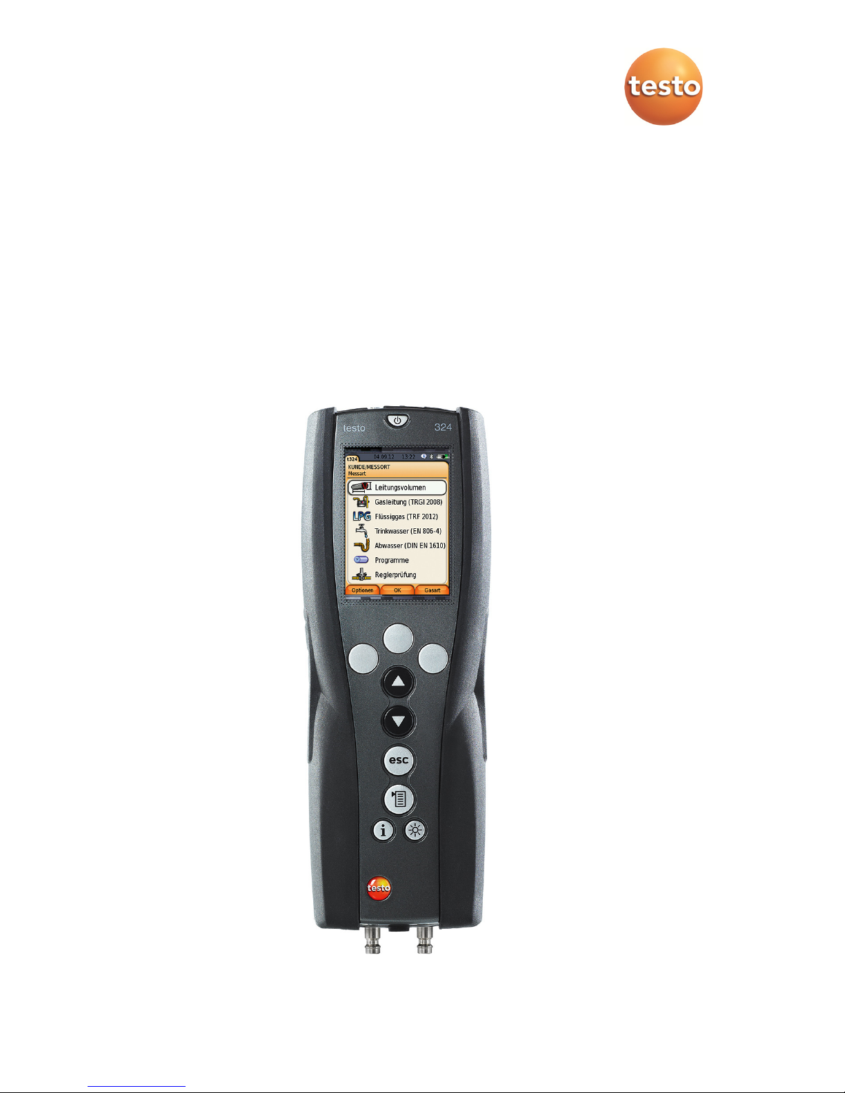
testo 324 - Leakage rates measuring instrument
Instruction manual
Page 2

2
Page 3

1 Contents
3
1 Contents
1 Contents ................................................................................................... 3
2 Safety and the environment .................................................................... 6
2.1. About this document ........................................................................ 6
2.2. Ensure safety ................................................................................... 8
2.3. Protecting the environment .............................................................. 9
3 Specifications ........................................................................................ 10
3.1. Use ................................................................................................ 10
3.1. Physical principles ......................................................................... 11
3.1.1. Physical influence of temperature on the
pressure to be measured ............................................................................... 11
3.1.2. The standardised measurement result of the testo 324
relating to temperature influences .................................................................. 11
3.2. Technical data ............................................................................... 12
3.2.1. Examinations and licenses ............................................................................ 12
3.2.2. Bluetooth® module (option) ............................................................................ 12
3.2.3. Declaration of conformity ............................................................................... 13
3.2.4. Measuring ranges and accuracies ................................................................. 13
3.2.5. Other instrument data .................................................................................... 14
4 Product description ............................................................................... 16
4.1. Measuring instrument .................................................................... 16
4.1.1. Overview ........................................................................................................ 16
4.1.2. Keypad .......................................................................................................... 17
4.1.3. Display ........................................................................................................... 18
4.1.4. Instrument connections .................................................................................. 19
4.1.5. Interfaces ....................................................................................................... 19
4.2. testo 324 in the case system with feeding unit .............................. 20
5 First steps .............................................................................................. 22
5.1. Commissioning .............................................................................. 22
5.2. Getting to know the product ........................................................... 22
5.2.1. Mains unit, rechargeable batteries ................................................................. 22
5.2.1.1. Charging the battery ........................................................................ 22
5.2.1.2. Rechargeable battery care .............................................................. 23
5.2.1.3. Mains operation ............................................................................... 23
5.2.2. Connecting hoses/probes .............................................................................. 23
5.2.3. Switching on .................................................................................................. 23
5.2.4. Calling up the function ................................................................................... 24
5.2.5. Entering values .............................................................................................. 24
5.2.6. Printing/saving data ....................................................................................... 26
5.2.7. Confirming an error message ......................................................................... 26
5.2.8. Switching off .................................................................................................. 27
5.3. Address/location ............................................................................ 27
Page 4

1 Contents
4
5.4.
Measurement records ................................................................... 29
5.5. Instrument diagnosis ..................................................................... 30
6 Using the product ................................................................................. 31
6.1. Performing settings ....................................................................... 31
6.1.1. Assigning the right function key ..................................................................... 31
6.1.2. Instrument settings ........................................................................................ 31
6.1.2.1. Units ................................................................................................ 31
6.1.2.2. Date/Time ........................................................................................ 32
6.1.2.3. Energy management ....................................................................... 32
6.1.2.4. Display brightness ........................................................................... 32
6.1.2.5. Printer ............................................................................................. 32
6.1.2.6. Bluetooth® ....................................................................................... 33
6.1.2.7. Automatic measuring rate ................................................................ 33
6.1.2.8. Inspector ......................................................................................... 34
6.1.2.9. Language ........................................................................................ 34
6.1.2.10. Country version ............................................................................... 35
6.1.2.11. Password protection ........................................................................ 35
6.1.3. Gas type ........................................................................................................ 36
6.2. Measuring ..................................................................................... 37
6.2.1. Preparing for measurement ........................................................................... 37
6.2.2. Options menu ................................................................................................ 38
6.2.3. Pipe volume ................................................................................................... 39
6.2.4. Gas pipe (TRGI 2008) ................................................................................... 40
6.2.4.1. Pretest ............................................................................................. 41
6.2.4.2. Main test .......................................................................................... 43
6.2.4.3. Leakage test (leakage measurement) ............................................. 44
6.2.4.4. Combined pretest/main test ............................................................. 47
6.2.4.5. Caravan Check ................................................................................ 48
6.2.5. Liquid gas (DVGW TRF 2012) ....................................................................... 50
6.2.5.1. Pressure test ................................................................................... 51
6.2.5.2. Main test .......................................................................................... 52
6.2.5.3. Repeated testing (PS>0.5 bar / PS<=0.5 bar) ................................. 53
6.2.5.4. Carrying out repeated testing PS <0.5 bar ....................................... 55
6.2.6. Drinking water (ZVSHK sheet as per DIN EN 806-4) ..................................... 56
6.2.6.1. Testing with air – main test .............................................................. 57
6.2.6.2. Testing with air – pretest ................................................................. 58
6.2.6.3. Test with water ................................................................................ 60
6.2.7. Waste water (DIN EN 1610) with air .............................................................. 62
6.2.8. Programs ....................................................................................................... 63
6.2.8.1. Spot measurement .......................................................................... 63
6.2.8.2. Programs 2-5 .................................................................................. 65
6.2.9. Controller test ................................................................................................ 68
6.2.9.1. Static pressure ................................................................................ 69
6.2.9.2. Flow pressure .................................................................................. 70
6.2.9.3. SAV_triggering pressure ................................................................. 71
6.2.9.4. SRV triggering pressure .................................................................. 72
6.3. Transferring data ........................................................................... 73
6.3.1. Record printer ................................................................................................ 73
6.3.2. PC/pocket PC ................................................................................................ 73
6.3.3. Data transfer to IrDA record printer ................................................................ 73
Page 5

1 Contents
5
7 Maintaining the product ........................................................................ 74
7.1. Cleaning the measuring instrument ............................................... 74
7.2. Regular calibration ......................................................................... 74
7.3. Replacing the gas bladder ............................................................. 74
8 Tips and assistance ............................................................................... 75
8.1. Questions and answers ................................................................. 75
8.2. Accessories and spare parts ......................................................... 75
8.3. Updating the instrument software .................................................. 77
Page 6
2 Safety and the environment
6
2 Safety and the environment
2.1. About this document
This document describes the product testo 324 with the instrument
setting Country version | Germany.
Use
> Please read this documentation through carefully and
familiarize yourself with the product before putting it to use. Pay
particular attention to the safety instructions and warning advice
in order to prevent injuries and damage to the products.
> Keep this document to hand so that you can refer to it when
necessary.
> Hand this documentation on to any subsequent users of the
product.
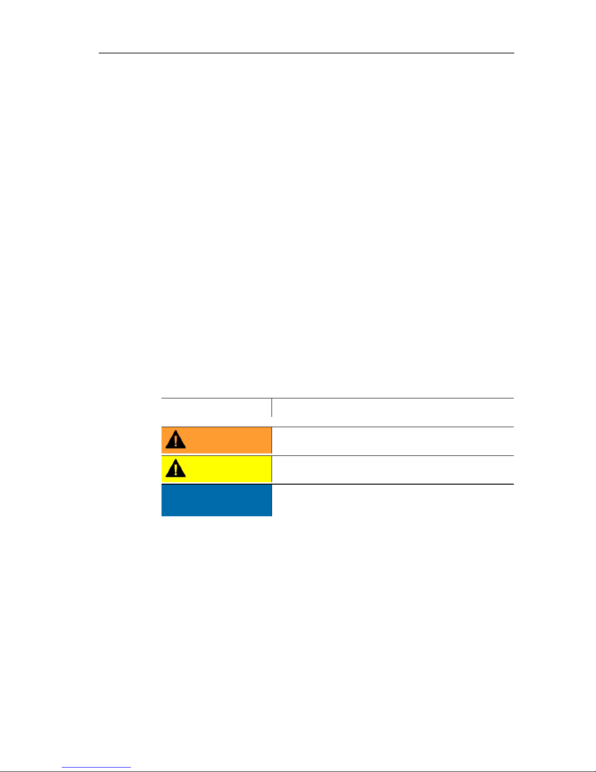
Warnings
Always pay attention to information that is marked by the following
warnings with warning pictograms. Implement the specified
precautionary measures.
Representation Explanation
WARNING
Indicates potential serious injuries
CAUTION
indicates potential minor injuries
NOTICE
indicates circumstances that may lead to
damage to the products
Page 7
2 Safety and the environment
7
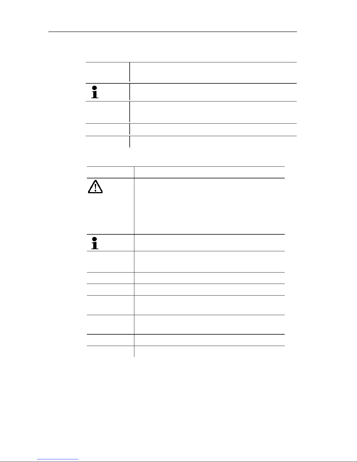
Symbols and writing standards
Representation
Explanation
Note: Basic or further information.
1. ...
2. ...
Action: more steps, the sequence must be followed.
> ... Action: a step or an optional step.
- ... Result of an action.
Symbols and writing standards
Display Explanation
Warning advice, risk level according to the
signal word:
Warning! Serious physical injury may occur.
Caution! Minor physical injury or damage to the
equipment may occur.
> Take the specified precautionary measures.
Note: Basic or further information.
1. …
2. …
Handling: several steps, the sequence must be
followed.
> … Handling: one step or optional step.
- … Result of an action.
Menu Elements of the instrument, the instrument
display or the program interface.
[OK] Control keys of the instrument or buttons of the
program interface.
… | … Functions/paths within a menu.
“…” Example entries
Page 8

2 Safety and the environment
8
2.2. Ensure safety
> Only operate the product properly, for its intended purpose and
within the parameters specified in the technical data. Do not
use any force.
> Do not operate the instrument if there are signs of damage at
the housing, mains unit or feed lines.
> Do not perform contact measurements on non-insulated, live
parts.
> Do not store the product together with solvents. Do not use any
desiccants.
> Carry out only the maintenance and repair work on this
instrument that is described in the documentation. Follow the
prescribed steps exactly. Use only original spare parts
from Testo.
> Any further or additional work must only be carried out by
authorised personnel. Testo will otherwise refuse to accept
responsibility for the proper functioning of the measuring
instrument after repair and for the validity of certifications.
> Only use the device in closed, dry rooms and protect it from rain
and moisture.
> Temperatures given on probes/sensors relate only to the
measuring range of the sensors. Do not expose handles and
feed lines to any temperatures in excess of 70 °C unless they
are expressly permitted for higher temperatures.
> The gas feeding unit should only be emptied in an open
environment.
> Do not operate the instrument if there are signs of damage at
the housing, mains unit or feed lines.
> Dangers may also arise from the systems being measured or
the measuring environment: Note the safety regulations valid in
your area when performing the measurements.
Page 9

2 Safety and the environment
9
For products with Bluetooth
®
(optional)
Changes or modifications that have been made without the explicit
consent of the responsible approval authority, may cause the
retraction of the type approval.
Data transfer may be disturbed by equipment that uses the same
ISM-band, e.g. WLAN, microwave ovens, ZigBee.
The use of radio communication links is not permitted, among
others, in aeroplanes and hospitals. For this reason the following
points must be ensured before entering:
> Switch off the device:
> Isolate the device from any external power sources (mains
cable, external rechargeable batteries, ...).
2.3. Protecting the environment
> Dispose of faulty rechargeable batteries/spent batteries in
accordance with the valid legal specifications.
> At the end of its useful life, send the product to the separate
collection for electric and electronic devices (observe local
regulations) or return the product to Testo for disposal.
Page 10
3 Specifications
10
3 Specifications
3.1. Use
testo 324
The testo 324 is a leakage measuring instrument for the
professional performance of the following measuring tasks:
• Pretest and main test on gas pipes
• Determining the usability of gas pipes
• Measuring low pressure against atmospheric pressure
• Pressure test on waste water pipes
• Pressure tests on liquid gas pipes
• Controller test
• Temperature measurement
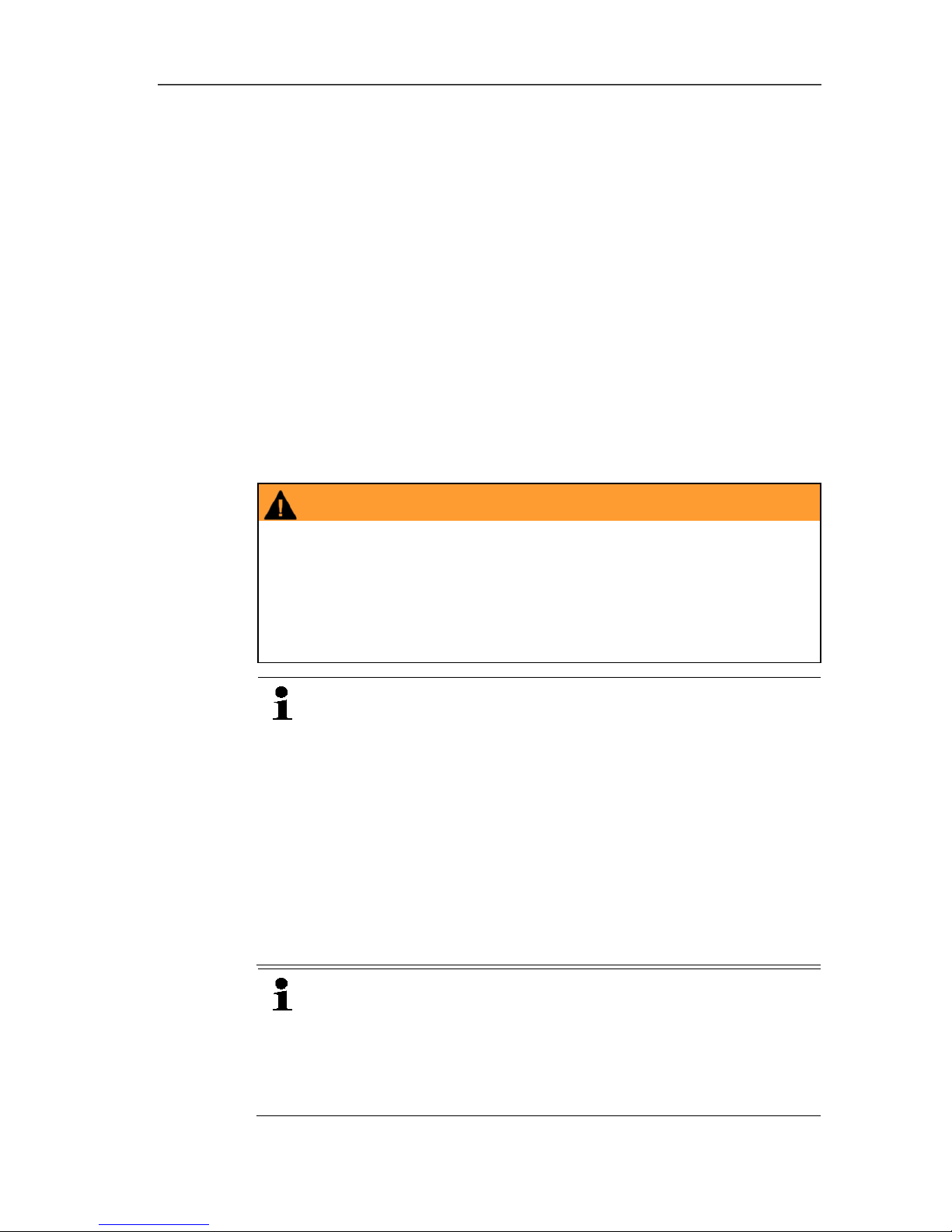
WARNING
Escaping gas can produce an explosive mixture of gases!
Potential risk of explosion!
> The testo 324 leakage measuring instrument may only be used
by authorised personnel who have been trained in the
maintenance and inspection of gas systems.
> Observe local accident prevention and test regulations.
Testo guarantees the functionality of its products when
used in accordance with their intended purpose. This
guarantee does not apply to features of Testo products in
combination with unauthorised third-party products.
Competitor products are not authorised by Testo.
As is common practice, Testo generally excludes support,
warranty or guarantee claims relating to functionality that
has not been guaranteed by Testo as part of the product
offered. Claims shall also be excluded in the event of
improper use or handling of the products, e.g. in
combination with unauthorised third-party products.
Further warranty terms: see website
www.testo.com/warranty.
testo 324 with Option Bluetooth
®
:
The use of the wireless module is subject to the regulations
and stipulations of the respective country of use, and the
module may only be used in countries for which a country
certification has been granted. The user and every owner
has the obligation to adhere to these regulations and
Page 11

3 Specifications
11
prerequisites for use, and acknowledges that the re-sale,
export, import etc. in particular in countries without wireless
permits, is his responsibility.
Feeding unit
When used in conjunction with the testo 324 leakage measuring
instrument, the feeding unit (gas bladder) enables leakage
measurement to be carried out independently of the gas supply.
3.1. Physical principles
3.1.1. Physical influence of temperature on the pressure to
be measured
Temperature fluctuations and positional changes have an effect on
the measuring accuracy of pressure measurements. The following
should therefore be observed:
✓ The entire measurement system must be adapted to the
ambient temperature and to the temperature of the line system
to be tested.
✓ The temperature of the measurement system and the line
system must remain stable during measurement.
Example of temperature influence:
with a test pressure of 100 hPa and an air pressure of 1000 hPa,
the ambient temperature changes from +22 °C to +23 °C. The air in
the test system expands and the test pressure increases by
3.73 hPa. The temperature influence on the pressure change is
unaffected by the test volume.
3.1.2. The standardised measurement result of the testo
324 relating to temperature influences
The testo 324 leak rate measuring instrument certified to
DVGW G 5952 enables measuring values to be reproduced.
Comparable results based on the standardised reference operating
pressure of 23 mbar are always achieved. The volume measured
during the test is based on a reference temperature of 20 °C and
the current air pressure.
A change in the ambient temperature therefore has no influence on
the measuring values!
The ambient temperature and the relevant test gas or medium for
each test section must nevertheless show a constant temperature
Page 12

3 Specifications
12
within the range of 15 °C to 25 °C with a maximum deviation of ±
2 °C. Only then can a measurement be carried out. During the
stability time at the start of each measurement, this check is carried
out automatically and a warning is issued if the temperature and
therefore the pressure fluctuates too greatly.
3.2. Technical data
3.2.1. Examinations and licenses
Tested in accordance with DVGW1 G5952 by DVGW Karlsruhe.
As declared in the Certificate of Conformity, this product complies
with Directive 2014/30/EU.
3.2.2. Bluetooth® module (option)
• Bluetooth® type: BlueGiga WT 11 / WT 11i-A (from
October 2013)
• Bluetooth
®
product note: WT11
• Bluetooth
®
identification: B017401 (WT 11) /
B017633 (WT11i-A)
• Bluetooth
®
company: 10274
Belgium (BE), Bulgaria (BG), Denmark (DK), Germany (DE),
Estonia (EE), Finland (FI), France (FR), Greece (GR), Ireland (IE),
Italy (IT), Latvia (LV), Lithuania (LT), Luxembourg (LU), Malta (MT),
Netherlands (NL), Austria (AT), Poland (PL), Portugal (PT),
Romania (RO), Sweden (SE), Slovakia (SK), Slovene (SI), Spain
(ES), Czech Republic (CZ), Hungary (HU), United Kingdom (GB),
Republic of Cyprus (CY).
EFTA countries
Iceland, Liechtenstein, Norway and Switzerland.
Other countries
USA, Canada, Turkey, Colombia, El Salvador, Venezuela,
Ecuador, New Zealand, Bolivia, Dominican Republic,
Peru, Chile, Cuba, Costa Rica, Nicaragua
1
German Technical and Scientific Association for Gas and Water
Page 13

3 Specifications
13
USA
FCC ID: QOQWT11l
This instrument complies with Part 15C of the FCC Rules and
Industry Canada RSS-210 (revision 8). Commissioning is subject to
the following two conditions: (1) This instrument must not cause
any harmful interference and (2) this instrument must be able to
cope with interference, even if this has undesirable effects on
operation.
Changes or modifications not expressly approved by the party
responsible for compliance could void the user's authority to
operate the equipment."
Canada
IC ID: 5123A-BGTWT11l
This instrument complies with Part 15C of the FCC Rules and
Industry Canada RSS-210 (revision 8). Commissioning is subject to
the following two conditions: (1) This instrument must not cause
any harmful interference and (2) this instrument must be able to
cope with interference, even if this has undesirable effects on
operation.
Cet appareil satisfait à la partie 15C des directives FCC et au
standard Industrie Canada RSS-210 (révision 8). Sa mise en
service est soumise aux deux conditions suivantes : (1) cet appareil
ne doit causer aucune interférence dangereuse et (2) cet appareil
doit supporter toute interférence, y compris des interférences qui
provoquerait des opérations indésirables.
Turkey
Authorized
3.2.3. Declaration of conformity
You can find the EU declaration of conformity on the Testo
homepage www.testo.com under the product-specific downloads.
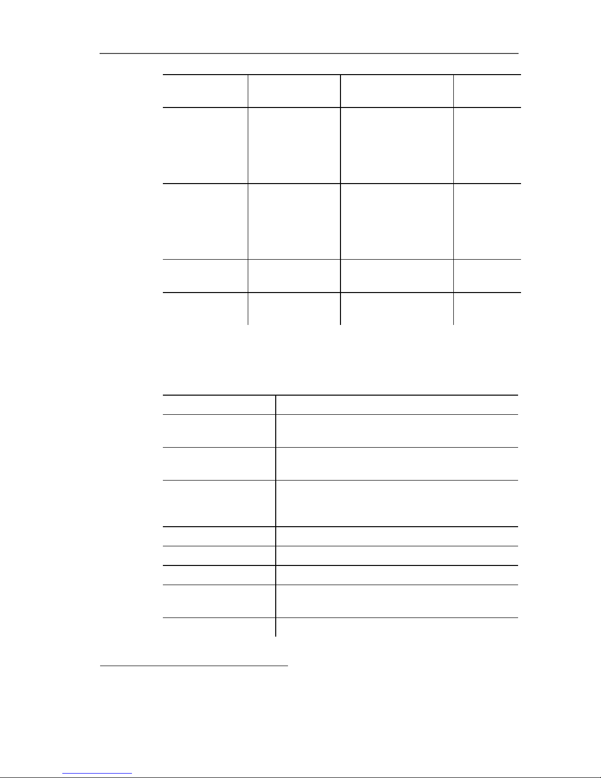
3.2.4. Measuring ranges and accuracies
Measurement
type
Measuring
range
Accuracy Resolution
Flow (Leakage
measurement)
0 to 10 l/h
±0.2 l/h or ±5% of
meas. val.
0.1 l/h
Pressure 0…1000 hPa
±0.5 hPa or ±3% of
meas. val.
0.1 mbar
Page 14
3 Specifications
14
Measurement
type
Measuring
range
Accuracy Resolution
Pressure
measurement
with a high
pressure probe
(optional)
0…25 bar
0…10 bar:
± 0.6 % of fullscale
>10…25 bar:
± 0.6 % of fullscale
10 hPa
Temperature
measurement
TC type K
(only instrument)2
-40…600 °C
± 0,5°C
(0,0...100,0 °C)
± 0,5% of meas. val.
(rest of range)
0,1°C
Instrument
overload
Max. 1200 hPa
Pipe volume
calculation
Max. 1200 l.
3
+/-0,2l or 5% of
meas. val. (1-200l)
3.2.5. Other instrument data
Flue gas analyser
Feature Values
Storage/transportati
on conditions
Temperature: -20 to 50°C
Operating
conditions
5 to 40°C
Power supply
Rech. batt.: Lithium-ion battery 11.0 V /
2400 mAh
Mains unit: 115-230 V – 50/60 Hz
Protection class IP40 acc. to EN 60529
Weight 1070 g (incl. battery)
Dimensions 270 x 90 x 75 mm
Additional probe
sockets
2 Hirschmann sockets for connecting
pressure probes and temperature probes
Gas connections 2 pressure connections DN 5
2
The accuracy of a connected temperature probe must also be taken into
account.
3
per 200 l: Test time 12 min
Page 15

3 Specifications
15
Feature Values
Interference
immunity and
interference
emission
According to DIN EN 61326-1
Memory 500,000 measuring values
Integrated pressure
pump
For test pressure build-up up to 300 mbar
and for filling the feeding unit
Display Graphic colour display, 240 x 320 pixels
Data transfer to PC USB or Bluetooth (option)
Battery charge time Approx. 5-6 h
Rech. batt. life > 5 h (pump on, 20°C ambient temperature)
Supported
testo printer
0554 0549, 0554 0547, 0554 0544 or
0554 0553, 0554 0620 (with Bluetooth
option)
Bluetooth® (option) Range < 10 m
Warranty Measuring instrument: 24 months
Thermocouple: 12 months
Rech. batt.: 12 months
Terms of warranty
Terms of warranty: see website
www.testo.com/warranty
Page 16
4 Product description
16
4 Product description
4.1. Measuring instrument
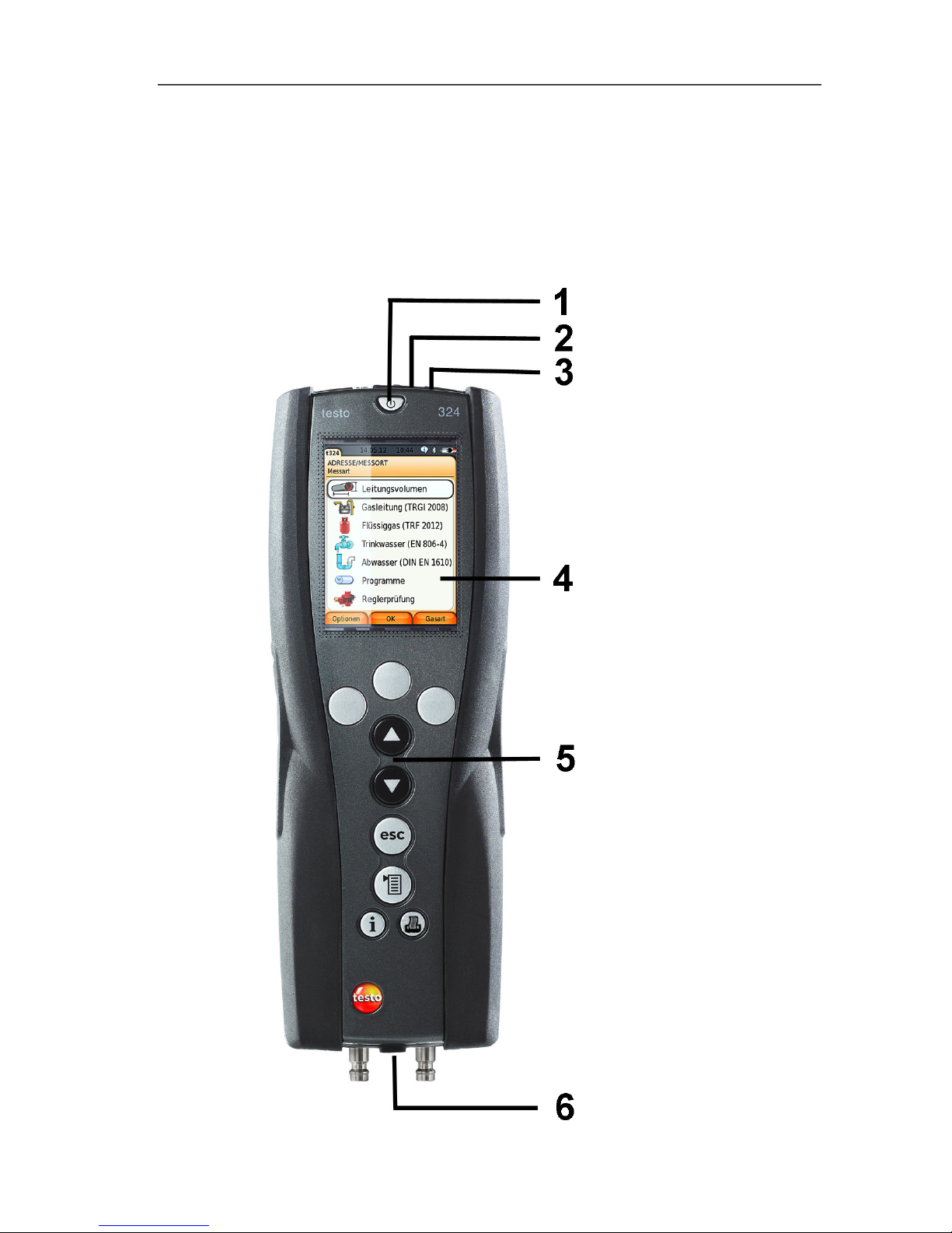
4.1.1. Overview
Page 17
4 Product description
17
1 Switch on/off
2 Attachment eye for carrying strap
3 Interfaces (USB, infrared) and reset button
CAUTION
Risk of injury from infrared beam!
> Do not direct infrared beam at human eyes!
4 Display
5 Keypad
6 Instrument connections
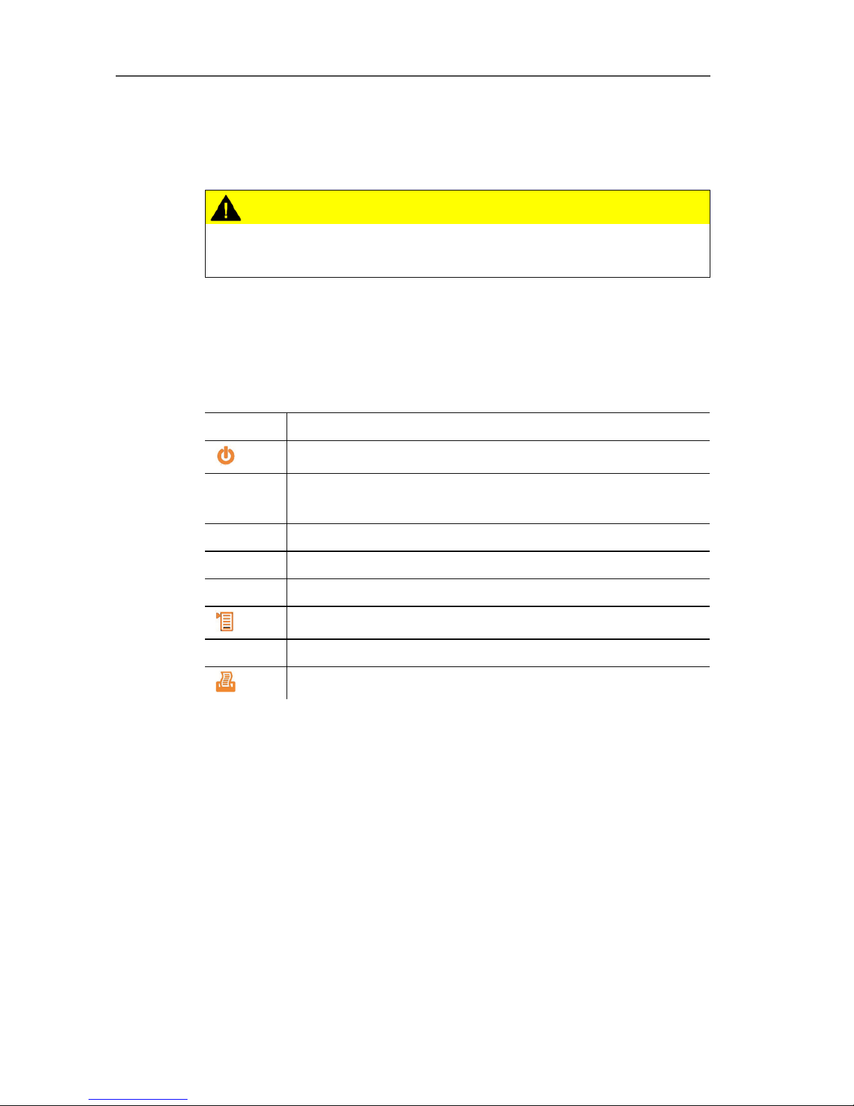
4.1.2. Keypad
Button Functions
[]
Switch measuring instrument on/off
[OK]
Example
Function key (grey, 3x), relevant function is shown on
the display
[▲]
Scroll up, increase value
[▼]
Scroll down, reduce value
[esc]
Back, cancel function
[]
Open main menu
[ i ]
Help texts, e.g. for individual measurements
[]
Transmit data to the record printer.
Page 18
4 Product description
18
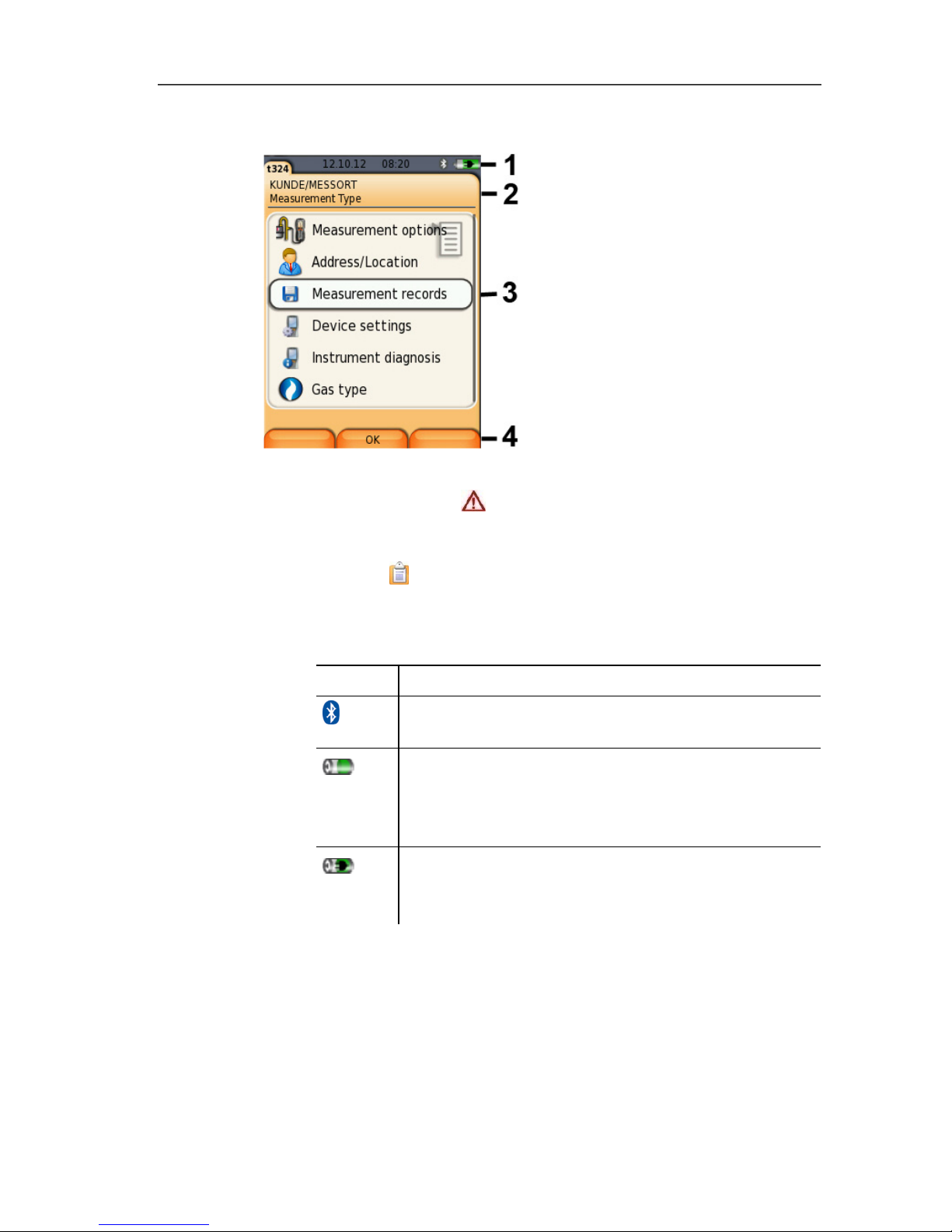
4.1.3. Display
1 Status bar (dark grey background):
• Warning symbol (only if there is an instrument error,
display of error in instrument diagnosis menu), otherwise:
Instrument designation.
• Symbol
• Display of date and time.
• Indication of Bluetooth
®
status, power supply and remaining
rechargeable battery capacity:
Symbol Feature
Blue symbol = Bluetooth
®
on,
Grey symbol = Bluetooth
®
off
Battery operation
Display of remaining rechargeable battery
capacity by colour and fill level of the battery icon
(green = 5 - 100%, red = < 5%)
Mains operation
Display of remaining rechargeable battery
capacity: see above
2 Info field of register tabs: Display of selected address/location,
selected measurement type.
3 Selection field for functions (selected menu item appears
against a white background, unavailable functions are identified
by grey font) or display of measuring values.
4 Function display for function keys.
Page 19
4 Product description
19
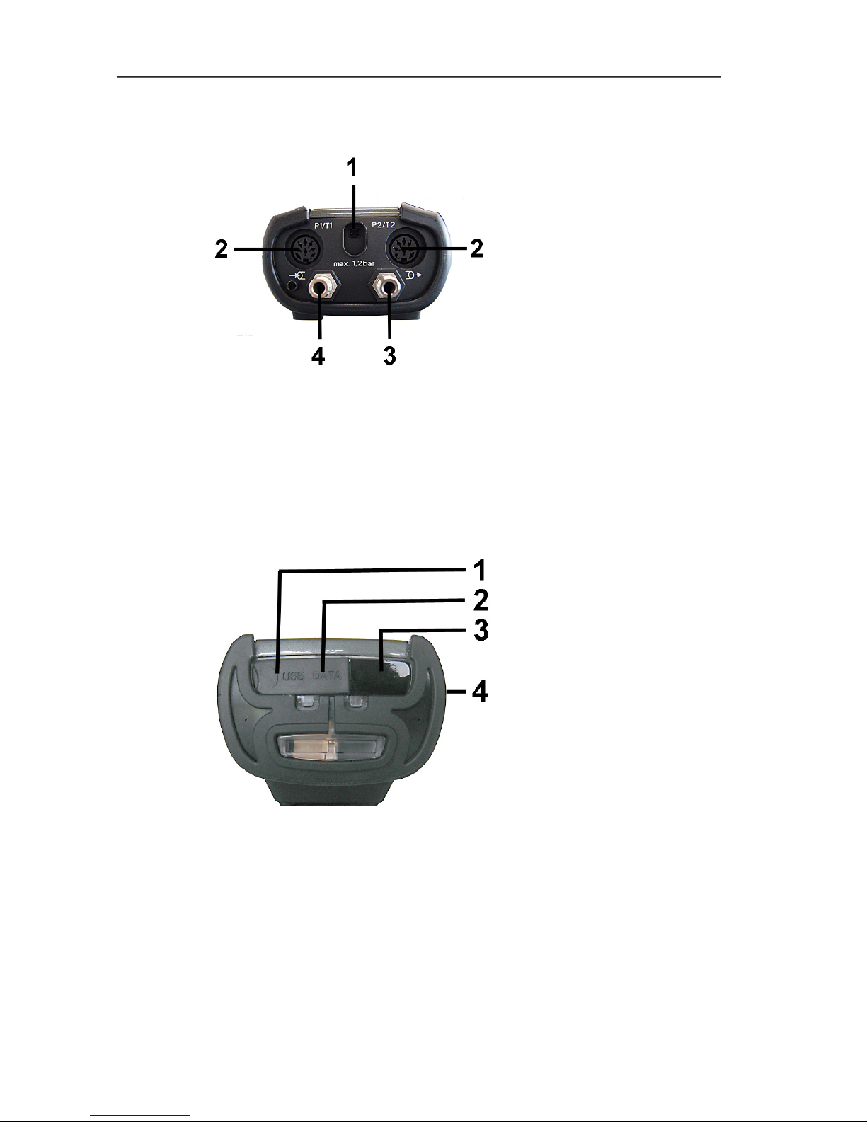
4.1.4. Instrument connections
1 Mains unit socket
2 Probe sockets for connecting the temperature probe or the high
pressure probes
3 Pressure connection 1.2 bar for connecting a pressure hose
4 Pressure connection for connecting a feeding unit or a pressure
hose
4.1.5. Interfaces
1 USB interface (under cover)
2 Reset button (under cover)
3 Infrared interface (IrDA)
4 Bluetooth interface (option)
Page 20
4 Product description
20
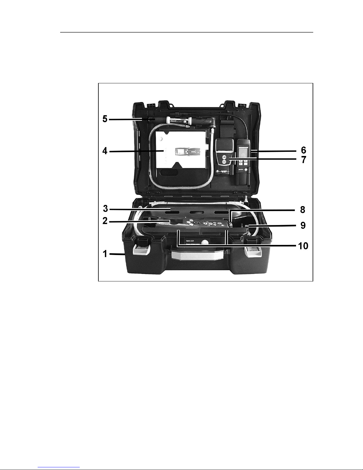
4.2. testo 324 in the case system with feeding unit
Overview
1 Transport case
2 testo 324
3 Feeding unit (gas bladder)
4 Storage compartment for instruction manual
5 Hand pump
6 Holder for gas leak detection instrument testo 316-2 or
testo 316-EX
7 Holder for IRDA or Bluetooth printer (option)
8 Connection for an external hand pump or a compressor
Page 21
4 Product description
21
9 Connection block with shut-off valve for pump, instrument and
hose connection
10 Storage compartments for accessories
Page 22

5 First steps
22
5 First steps
5.1. Commissioning
testo 324
The testo 324 has a permanently installed rechargeable battery.
> Charge the rechargeable battery fully before using the
measuring instrument.
> Remove the protective film from the display.
Feeding unit
Flushing is required when starting up the unit for the first time, after
replacing the gas bladder and when changing the medium.
> Fill and empty the feeding unit once, see Options menu, page
38
5.2. Getting to know the product
5.2.1. Mains unit, rechargeable batteries
In case of an extended interruption in the power supply to
the testo 324 (e.g. rechargeable battery pack empty), the
date/time settings will be lost.
5.2.1.1. Charging the battery
The rechargeable battery can only be charged at an ambient
temperature of 5 to +35 °C. If the rechargeable battery pack has
discharged completely, the charging time at room temperature is
approx. 5 - 6 h (charging with mains adapter).
Charging via a mains unit
✓ The testo 324 is off.
1. Connect the mains unit instrument plug to the mains unit
socket.
2. Connect the mains plug of the mains unit to a mains socket.
- The charging process starts. The charge status is shown on the
display.
- Once the rechargeable battery has been charged, the
instrument switches over automatically to trickle charge.
Page 23
5 First steps
23
5.2.1.2. Rechargeable battery care
> Do not fully exhaust rechargeable batteries.
> For extended periods of disuse, you should discharge and
recharge the batteries every 3 - 4 months. Trickle charging
should not exceed 2 days.
5.2.1.3. Mains operation
In case of danger, the instrument must be disconnected
from the power supply by simply pulling out the mains
cable.
> Always position the instrument so that the power supply plug
can be easily reached.
1. Connect the mains unit instrument plug to the mains unit
socket.
2. Connect the mains plug of the mains unit to a mains socket.
- The power supply is provided by the mains unit.
- If the testo 324 is switched off, the rechargeable battery
charging process starts automatically. Switching on the testo
324 stops the battery charging and the instrument is then
powered via the mains unit.
5.2.2. Connecting hoses/probes
> Connect the required hoses/probes at the corresponding
connections.
5.2.3. Switching on
> Press [].
When the instrument is switched on, the valves of the
testo 324 are activated. Four short acoustic signals are
output.
If fewer than 4 acoustic signals are sounded, the testo 324
must be switched on and off several times before use until
4 signals are sounded.
The testo 324 then starts up as usual.
- The start screen is displayed (duration: approx 15 s).
- If the voltage supply was interrupted for an extended period:
The Date/Time menu is opened.
- The pressure sensors are zeroed.
- If there is an instrument error, the Error diagnosis menu is
displayed.
- The Measurement options menu is displayed.
Page 24
5 First steps
24
5.2.4. Calling up the function
1. Select function: [▲], [▼].
- A box appears around the selected function.
2. Confirm selection: [OK].
- The selected function is opened.
5.2.5. Entering values
Some functions require values (numbers, units, characters) to be
entered. Depending on the selected function, the values are
entered either via a list field or an input editor.
List field
1. Select the value to be changed (numerical value, unit): [▲],
[▼], [◄], [►] (depending on the selected function).
2. Press [Edit] .
3. Set value: [▲], [▼], [◄], [►] (depending on the selected
function).
4. Confirm the entry: [OK].
5. Repeat steps 1 and 4 as required.
6. Save the entry: [Finished].
Page 25

5 First steps
25
Input editor
1. Select the value (characters) to be changed: [▲], [▼], [◄],
[►].
2. Adopt the value: [OK].
Options:
> Toggle between upper/lower case:
select Ι
← ABC→&$/ →Ι : [▲], [▼] → [ABC→&$/].
> Position the cursor in the text:
select Ι
← ABC→&$/ →Ι : [▲], [▼] → [Ι←] or [→Ι].
> Delete character before or after the cursor:
select Del Finished
←: [▲], [▼] → [←] or [Del].
3. Repeat steps 1 and 2 as required.
4. Save the entry: select Del Finished
← : [▲], [▼] →
[Finished].
Page 26

5 First steps
26
5.2.6. Printing/saving data
Data is printed out via the key [].
To be able to transfer data to a record printer via infrared or
Bluetooth interface, the printer used must be enabled, see Printer,
page 32
Data is saved via the Options menu. The Options menu is
accessed via the left function key and is available in many different
menus.
Once a measurement has been carried out, the measurement
result can be saved via the right function key Save. Assignment of
the right function key with the function Save or Print, see
Assigning the right function key page 31.
With other functions, saving is carried out automatically via the
function key Finished, e.g. when creating Address/Location or
entering Date/Time.
5.2.7. Confirming an error message
If an error occurs, an error message is shown on the display.
> Confirm error message: [OK].
Errors that have occurred but have not yet been rectified are
indicated by a warning symbol ( ) in the header.
Error messages not yet resolved can be displayed in the menu
Error diagnosis, see Instrument diagnosis, page 30.
Page 27

5 First steps
27
5.2.8. Switching off
Unsaved measuring values are lost if the testo 324 is
switched off.
> Press [].
- The measuring instrument switches off.
5.3. Address/location
All measuring values can be saved under the currently active
location. Measuring values that have not been saved are lost when
the measuring instrument is switched off!
Addresses and locations can be created, edited, copied and
enabled. Addresses and locations (incl. records) can be deleted.
Call up function:
> [] → Address/Location → [OK] .
There are various options for opening folders.
1. Edit search setting (Search / Filter / Show all): [Edit]
2. Select search setting: [▲], [▼] → [OK].
Possible settings:
• Show all: all addresses/locations are displayed
• Search: A search text only brings up addresses/locations
that contain characteristics of the search text.
• Filter: Individual letters or numbers can be selected. All data
beginning with the relevant letter/number is displayed.
The initial letter is the determining factor for the filter
function, and this can only be selected individually. The
search function can also be used to find a series of several
letters within the folder name!
3. Carry out search according to search setting: [Search]
Show all
1. Select address: [▲], [▼].
2. Show details: [Details].
3. Enable location: select location → [OK].
- The location is enabled.
> Open measurements menu: press [OK] again.
Page 28

5 First steps
28
Search
1. Edit search criterion: [►] → [Edit].
2. Select search criteria: [▲], [▼] → [OK].
Possible options:
• Contact person
• Folder name
• Town/city
• Postcode
• Street
- The selected criterion is displayed.
3. Call up entry field for search text: [►] or [▼]
> Enter search text → [Finished]
Filter
1. Edit search criteria: [Edit].
2. Select search criteria: [▲], [▼] → [OK].
Possible options:
• Contact person
• Folder name
• Town/city
• Postcode
• Street
- The selected criterion is displayed.
3. Enable tab: [▼]
4. Select the required tab: [▲], [▼] and sometimes [◄], [►] →
[Filter].
- The search result for the relevant letter or number is displayed.
Creating a new location:
A measuring location is always created under an address.
1. Select the address under which the location should be created.
2. [Options] → New location → [OK].
3. Enter values or make settings.
4. Finalise the entry: [Finished].
Other location options:
> [Options] → Edit location: make changes to an existing
location.
> [Options] → Copy location: make a copy of an existing
location in the same folder.
> [Options] → Delete location: delete an existing location.
Page 29

5 First steps
29
Creating new addresses:
1. [Options] → New address → [OK].
2. Enter values or make settings.
3. Finalise the entry: [Finished].
Additional address options:
• Edit address: make changes to an existing folder.
• Copy address: make a copy of an existing address.
• Delete address: delete an existing address, including the
locations created there.
• Delete all addresses: delete all existing addresses, including
the locations created there.
5.4. Measurement records
Call up function:
> [] → Measurement records → [OK].
There are various options for opening records, see
Address/location, page 27.
Displaying a record:
1. Select the required record from the detailed view.
2. [Data].
Options:
> [Options] → Show Graphic: display saved record data as
graphic.
> [Options] → Delete Record: delete the selected record.
> [Options] → Number of lines: change the number of
measuring values per display page.
> [Options] → Delete all records: delete all saved records for a
location.
Page 30

5 First steps
30
5.5. Instrument diagnosis
Important operating values and instrument data are displayed. A
main test can be carried out. Instrument errors that have not yet
been rectified can be displayed.
Call up function:
> [] → Instrument diagnosis → [OK].
Error diagnosis
> Error diagnosis → [OK].
- Unresolved errors, warnings and notes are displayed.
> View next/previous error: [▲], [▼].
Instrument information
> Device Information → [OK].
- Information is displayed.
Tightness test
1. Main test → Tightness test → [OK]
2. Short both gas connections through the connection hose.
3. Start the check: [OK].
- Zeroing of pressure sensor
- Pressure is built up and measurement is carried out
- The result of the measurement is indicated by a traffic light.
Gas feeding unit test
1. Gas feeding unit test → [OK].
2. Connect the measuring instrument to the gas feeding unit.
3. Start the test: [OK].
- If the gas feeding unit is full, it is emptied.
4. Gas feeding unit is filled.
• Settling period expires (15 min)
• Measuring time expires (5 min)
- The measurement result is indicated by a traffic light.
5. Gas feeding unit is emptied.
6. Exit testing: [Back]
Page 31

6 Using the product
31
6 Using the product
6.1. Performing settings
6.1.1. Assigning the right function key
The right function key can have a function from the Options menu
assigned to it. The menu Options is accessed via the left function
key and is available in many different menus. This assignment is
only valid for the currently opened menu / the opened function.
✓ A menu / function is opened in which the Options menu is
displayed on the left function key.
1. Press [Options] .
2. Select option: [▲], [▼].
Depending on the menu / function from which the Options menu
was opened, the following functions are available.
3. Assign the selected function to the right function key: Press
[Config. Key].
6.1.2. Instrument settings
It is assumed that the contents of the chapter First steps
(see First steps, page 22) are known.
Calling up a function:
> [] → Device Settings.
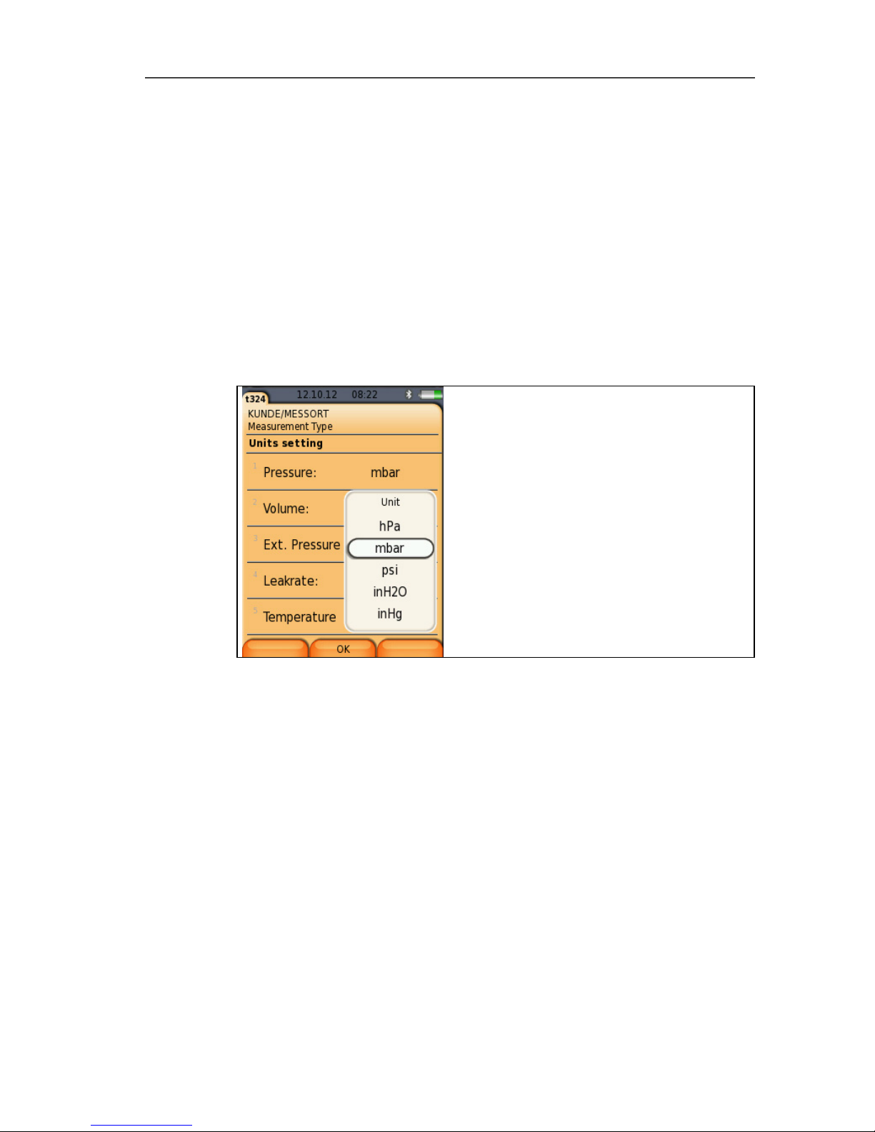
6.1.2.1. Units
The units used for parameters in configuration menus can be set.
Call up function:
> [] → Instrument settings → [OK] → Units → [OK].
Adjustable units
Parameter Unit
Pressure
hPa, mbar, psi, inW,
inHg
Volume m3, l, ft3
Ext. Pressure bar, psi, kPa
Leakrate l/h, fl.oz, ml/min
Page 32

6 Using the product
32
1. Select the line: [▲], [▼] → [Edit].
2. Select the unit to be changed: [▲], [▼] → [OK].
3. Confirm the entry: [Finished].
6.1.2.2. Date/Time
Date, time mode and time can be set.
Calling up the function:
> [] → Instrument settings → [OK] → Date/Time → [OK].
Set date/time:
1. Select parameter: [◄], [▲], [▼] → [Edit].
2. Set parameter: [▲], [▼] and sometimes [◄], [►] → [OK].
3. Save settings: [Finished].
6.1.2.3. Energy management
Automatic instrument shutdown (Auto-Off) and switching off of the
display light in battery operation can be set.
Calling up the function:
> [] → Instrument Settings → [OK] → Energy Management
→ [OK]
Making settings:
1. Select function or parameter: [▲], [▼] → [Edit].
2. Set parameter: [▲], [▼] and partly [◄], [►] → [OK].
3. Save changes: [Finished].
6.1.2.4. Display brightness
The intensity of the display illumination can be set.
Calling up the function:
> [] → Instrument Settings → [OK] → Display Brightness →
[OK]
Performing settings
> Set parameter: [◄], [►] → [OK].
6.1.2.5. Printer
The headers (lines 1-3) and the footer for the printout can be set.
The printer that is used can be enabled.
Call up function:
> [] → Instrument settings → [OK] → Printer → [OK].
Page 33

6 Using the product
33
Enabling the printer:
The 0554 0553 and 0554 0620 printers can only be
selected if the Bluetooth® interface is enabled, see
Bluetooth®, page 33.
When using the testo IrDA record printer 0554 0547, the
testo IrDA fast printer 0554 0549 must be selected.
Graphics can be printed out using the following Testo
printers:
0554 0547 IrDA report printer
0554 0549 IrDA report printer
0554 0553 Bluetooth® printer
0554 0620 Bluetooth® printer
1. Select printer → [OK].
2. Select the printer: [▲], [▼] → [OK].
- The printer is enabled and the Printer menu is opened.
Setting the print text:
1. Print text → [OK].
2. Select function: [▲], [▼] → [Edit].
3. Enter values → [OK].
4. End input: [Finished].
5. Save the entry: [Finished].
6.1.2.6. Bluetooth®
This menu is only available if the instrument is equipped with
Bluetooth. The Bluetooth module can be switched on / off.The relay
can now be tested.
Calling up the function:
> [] → Instrument Settings → [OK] → Bluetooth → [Edit].
Making settings:
> Set parameter → [OK].
6.1.2.7. Automatic measuring rate
The automatic measuring rate can be switched on or off.
If the automatic measuring rate is on, the following measuring rate
is saved for the individual measurement programs (except
Programs menu):
Page 34

6 Using the product
34
Messzeit Measuring rate
< 15 min 1 s
> 15 min 1 min
If the automatic measuring rate is switched off, a measuring rate of
1 second is used, irrespective of the measuring time.
Call up a function:
> [] → Instrument settings → [OK] → Autom. meas. rate →
[OK].
Making settings:
1. [Edit]
2. Set parameter: [▲], [▼] → [OK].
6.1.2.8. Inspector
In this menu, an inspector can be selected and/or a new one can
be created.
Calling up the function:
> [] → Instrument settings → [OK] → Inspector → [OK].
Making settings:
1. Edit/create inspector: [▼] → [Edit] → [Finished].
2. Set parameter: [▲], [▼] and sometimes [◄], [►] → [OK].
3. Save changes: [Finished].
4. [Finished].
Selecting an inspector
> Select inspector: [▲], [▼] → [Enable] → [Finished].
6.1.2.9. Language
The menu language can be set. The number of available
languages depends on the activated country version, see Country
version, page 35.
Calling up the function:
> [] → Instrument Settings → [OK] → Language → [OK]
Activating the language:
> Select the language → [OK].
Page 35

6 Using the product
35
6.1.2.10. Country version
The country version with national defaults (measurement types,
standard values) can be set. The selection of the country version
influences the menu languages that can be enabled.
Call up function:
> [] → Instrument settings → [OK] → Country version →
[OK].
This setting can be password protected. A password is
specified in the menu Password Protection, see
Password protection, page 35.
Possibly:
> Enter password: [Enter] → Enter password → [Finished] →
[OK].
Setting the country version:
1. Select the country version: [▲], [▼] → [OK].
2. Confirm confirmation request: Yes → [OK]
- The system is restarted.
6.1.2.11. Password protection
The password protection is only valid for functions identified by the
following symbol: or .
Password protection can be enabled/disabled, the password can
be changed.
To disable password protection, change the password to 0000
(factory setting).
Call up function:
> [] → Instrument settings → [OK] → password protection
→ [OK].
Possibly:
> Enter the current password:
[Enter] → Enter password → [Finished] → [OK].
Changing the password:
1. [Edit].
2. Enter a new password → [Finished].
3. [Edit].
4. Enter the new password again to confirm → [Finished].
5. Save changes: [Finished].
Page 36

6 Using the product
36
6.1.3. Gas type
The gas type can be selected. The gas-specific coefficients and
threshold values can be set.
In order to maintain the measuring accuracy of the
instrument, the correct gas must be selected or configured.
Correct representation of measuring results is only assured
if the threshold values for the ideal range of the
corresponding measurement task have been set correctly.
Preset threshold values are typical values for the selected
gas type.
Gas Standard
designation
Gas
composition
Measuring
range
Natural gas
(G20)
Complies with
G20
Methane 100% 0 to 10 l/h
Natural gas
(G25)
Complies with
G25
Methane 86%
Nitrogen 14%
0 to 10 l/h
Propane G31
G31 burner
test gas
Propane 100% 0 to 5 l/h
Propen G32
G32 burner
test gas
Propen 100% 0 to 5.7 l/h
G21
G21 burner
test gas
EN 437,
DIN 3362
Methane 87%
Propane 13%
0 to 10 l/h
G30
G30 burner
test gas
n-butane 50%
Iso-butane 50%
0 to 3.2 l/h
Air -
Nitrogen 78%
Oxygen 21%
0 to 10 l/h
CO2 -- CO2 100% 0 to 9 l/h
Call up function:
> [] → Gas type → [OK].
Enabling gas type:
> Select the gas type → [OK].
- The gas type is enabled and the main menu is opened.
Page 37

6 Using the product
37
Setting coefficients:
1. Select gas type → [Coeff.].
2. Select the coefficients: [Edit].
Possibly:
> Enter password: [Enter] → Enter password → [Finished] →
[OK].
3. Set values → [OK].
4. Save changes: [Finished].
6.2. Measuring
6.2.1. Preparing for measurement
The feeding unit (gas bladder) must be tested for leaks at
regular intervals, see Instrument diagnosis, page 30, gas
feeding unit test.
Caution
Avoid damage to the instrument due to high pressure!
> For tests with a test pressure of > 1 bar or using a liquid test
medium e.g. water, a high pressure probe (art. no. 0638 1748)
must be used.
The First steps chapter (see First steps, page 22) must
have been read.
General information on the tightness tests on gas and
water pipes according to DVGW
• Before starting work on pipes carrying gas, the relevant
shut-off device must be closed and secured against
opening by unauthorised persons (e.g. when the key or
the hand wheel is removed). Where gas escapes or
could escape, it is necessary to ensure that the gas is
disposed of safely through ventilation or routing it
outdoors via a hose. The shut-off device should only be
opened again when all openings of the pipes through
which gas could escape have been tightly sealed. The
above does not apply when dealing with external
maintenance measures on pipes.
• If a leak is detected in accessible pipes carrying gas
using a gas detector in accordance with DVGW advice
G465-4 or with foaming agents in accordance with DIN
EN 14291, the point must be sealed by means of
suitable measures. Illumination with flames is not
Page 38

6 Using the product
38
permitted. Temporary sealing is only permissible in the
short term to avoid immediate risks.
• Pipes with operating pressures up to 100 mbar are
subject to a pretest and a main test, as well as a
serviceability test (for system in operation). The tests
should be carried out before the pipe is plastered over
or covered and its connections are coated or encased.
The tests can also be carried out in step-by-step.
• All tests must be documented.
To protect the testo 324, it is necessary to ensure that the
gases flowing into the pipes are free of oil, dust and
moisture.
Setting the location and gas type
Before carrying out measurements, the location and gas type must
be correctly selected, see Address/location, page 27 and see Gas
type, page 36.
6.2.2. Options menu
In the Measurement Type menu, for the various measurement
types, under [Options], the following selection is available:
> [Options] → Address/Location: The Address/Location folder
is opened.
> [Options] → Gas type: The Gas type folder is opened.
> [Options] → Main test: A main test can be carried out.
> [Options] → Please empty gas feeding unit: If a gas feeding
unit is available, this is emptied automatically.
This option is only available in conjunction with a feeding
unit.
> [Options] → Release air: Air is released from the pipe into the
environment.
> [Options] → Release gas: Gas is released from the pipe into
the gas feeding unit.
This option is only available in conjunction with a feeding
unit.
There are other options depending on the measurement type used.
Page 39

6 Using the product
39
6.2.3. Pipe volume
Based on the pipe volume calculation, unknown pipe volumes can
be determined and allocated to the relevant measuring location.
Particularly for the tightness test, where the stability time and
measurement time depends on the pipe volume, the advantage is
even more accurate and more reliable measurement.
Calling up the function:
> [] → Measurements → [OK] → Pipe volume → [OK].
Setting parameters
Parameter Selection Explanation
Gas feeding unit Yes/No Enable/disable gas feeding
unit
Test gas Air, CO2,
G30, G21,
propane,
natural gas,
Select test gas
1. Select parameter → [Edit].
2. Select or enter values: [▲], [▼] and sometimes [◄], [►] →
[OK].
Carrying out the measurement:
3. Start measurement: [].
> When Gas feeding unit Yes is selected: carry out steps in
accordance with the information on the display and confirm with
[OK].
- Zeroing starts (5 s)
- Volume calculation is carried out (bar shows progress of the
calculation)
-
Volume is displayed.
4. Adopt measurement result: [Apply].
Page 40

6 Using the product
40
6.2.4. Gas pipe (TRGI 2008)
WARNING
Risk of explosion due to hazardous gas/air mixtures
> Do not feed air into pipes carrying gas.
> Observe the information for the instrument if there is a risk that
air is being routed into pipes carrying gas.
CAUTION
Avoid damage to the instrument due to high pressure!
> The test pressure of 1.2 bar must not be exceeded.
There are 5 different test types to choose from:
Test type Explanation
Pretest The pretest (using air) is used for the load
test (stability test) of newly laid gas pipes.
The test is performed on the pipe without
gas meter and fittings.
Main test
The main test (using air or inert gas, e. g.
CO
2
or N2) is used for the tightness test
(acceptance test) on newly laid or
renovated pipes. The test is performed at
the pipe, including the fittings, without gas
installations and corresponding control
and safety equipment.
Leakage test
This measurement is carried out to test
the serviceability of an existing gas pipe
system and is used to check the actual
condition of the pipes. The pipe system
may be in operation or disused. After
handover of a gas system, the operator is
responsible for proper operation, which is
why it is recommended that the
serviceability test is carried out every 12
years.
Page 41

6 Using the product
41
Test type Explanation
Combined
pretest/main test
This measurement is carried out for newly
laid pipe systems with operating
pressures of 100 mbar to 1 bar.
The test includes pipe systems including
fittings, but without gas pressure
controllers, gas appliances, gas meters
and relevant regulating and safety
devices.
Caravan check
Tightness test on gas pipes in
accordance with the EN 1949 standard
and DVGW G 607. Since1 April 2006, a
valid G 607 test is a requirement for the
HU (general inspection) with the TÜV
(German Technical Inspection Agency).
Caravan and motorhome owners are
obliged to have their liquid gas systems
checked every 2 years.
6.2.4.1. Pretest
This test is used as a load test for newly laid gas pipes and is
carried out before the main test. The test is performed on the pipe
without a gas meter and fittings. The pipe is subjected to many
times the subsequent operating pressure, so the material is
exposed to a significantly greater load than is expected during
normal operation.
Calling up the function:
> [] → Measurements → [OK] → Gas pipe (TRGI 2008 →
Pretest → [OK].
Setting parameters
Parameter Explanation
Stability time Set stability time
Measurement period Adopt or set measurement period
According to DVGW TRGI 2008,
the measurement period is 10
min.
Page 42

6 Using the product
42
Parameter Explanation
Test pressure (target) Adopt or set test pressure
According to DVGW TRGI 2008,
the test pressure (target) is
1000 mbar
Pressure Set pressure
1. Edit values: [Edit].
2. Enter values. [▲], [▼] and sometimes [◄], [►] → [OK].
Carrying out a pretest
1. Build up test pressure (target) manually with the test pump or a
compressor at the connection provided.
2. Close the shut-off valve.
The valve must always be closed during measurements.
Only open to apply pressure. Close it again
3. Start measurement: [].
- Zeroing starts (5 s)
Option
> End stability time early: [Next]
> End measurement period early: [Next]
- Pretest is ended.
4. Evaluate measurement result: [▲], [▼] → [OK].
- The measurement result is displayed
5. Save measurement result: [Save].
Options
> [Options] → Show Graphic: a section of past measuring
values is displayed in a line graph (zoom function available [▲],
[▼]).
> [Options] → Manometer: the measuring values are displayed
in the same way.
> [Options] → Factory setting: the values are reset to the
default settings.
> [Options] → Overall graphic curve: the measuring values
across the overall measuring time are displayed in a line graph.
Page 43

6 Using the product
43
6.2.4.2. Main test
The main test (using air or inert gas such as CO2 or N2) is a
tightness test for pipes including fittings, but without gas appliances
and the relevant regulating and safety devices. The main test is
carried out after a successfully completed pretest on newly laid gas
pipes or after renovation of existing gas pipes and is used for the
acceptance of these pipes. It shows up even the smallest leaks in
gas pipes.
Calling up the function:
> [] → Measurements → [OK] → Gas pipe (TRGI 2008 →
Main test → [OK].
Setting parameters
According to DVGW TRGI 2008, the stability time and
measurement period depend on the pipe volume.
• Pipe volume < 100 l: Adjustment time 10 min,
measurement period 10 min.
• Pipe volume > 100 l - < 200 l: Adjustment time 30 min,
measurement period 20 min.
• Pipe volume > 200 l: Adjustment time 60 min,
measurement period 30 min.
Parameter Explanation
Volume Set volume
The pipe volume can also be
measured directly, see [Options]
→ Volume
Stability time Set stability time
Measurement period Set measurement period
Test pressure (target) Set test pressure
According to DVGW TRGI 2008,
the test pressure (target) is
150 mbar.
1. Edit values: [Edit].
2. Enter values. [▲], [▼] and sometimes [◄], [►] → [OK].
Page 44

6 Using the product
44
Carrying out a main test
1. Start measurement: [].
- Zeroing starts (5 s)
- Test pressure (target) is built up automatically by the instrument
Option
> End stability time early: [Next]
> End measurement period early: [Next]
- Main test is ended.
2. Evaluate measurement result: [▲], [▼] → [OK].
- The measurement result is displayed
3. Save measurement result: [Save].
Options
> [Options] → Show Graphic: a section of past measuring
values is displayed in a line graph (zoom function available [▲],
[▼]).
> [Options] → Volume: The pipe volume is determined directly
(the option is no longer available after the measurement).
> [Options] → Manometer: The measuring values are displayed
in the same way.
> [Options] → Factory setting: the values are reset to the
default settings.
> [Options] → Overall graphic curve: the measuring values
across the overall measuring time are displayed in a line graph.
6.2.4.3. Leakage test (leakage measurement)
This measurement is carried out to test the serviceability of an
existing gas pipe system (in contrast to the pretest and main test)
and is used to check the actual condition of the pipes. The pipe
system may be in operation or disused
For the serviceability test, the testo 324 can be operated together
with the feeding unit. The feeding unit supplies the test medium
(gas or air).
The advantages of a measurement with the feeding unit:
• Pressure fluctuations that may occur in gas pipes and affect the
measurement are compensated (test independent of the gas
supply).
• No need to dismantle the gas meter/the instrument can be used
at any point on the system.
• Safe measurements thanks to the feed-in of gas, as there is no
risk caused by air in a pipe carrying gas.
Page 45

6 Using the product
45
Test pressure:
• Operating pressure <30 mbar = reference pressure (23 mbar)
• Operating pressure >30 mbar = operating pressure
According to DVGW TRGI 2008, the stability time and
measurement period depend on the pipe volume.
• Pipe volume < 100 l: Adjustment time 10 min,
measurement period 5 min.
• Pipe volume < 200 l: Adjustment time 30 min,
measurement period 10 min.
• Pipe volume < 300 l: Adjustment time 60 min,
measurement period 15 min.
• Pipe volume < 400 l: Adjustment time 120 min,
measurement period 20 min.
• Pipe volume < 500 l: Adjustment time 240 min,
measurement period 25 min.
Calling up the function:
1. [] → Measurements → [OK] → Gas pipe (TRGI 2008 →
Leakage test → [OK].
2. Select Feeding with gas (feeding unit required), Feeding with
air, as gas meter replacement: [▲], [▼] → [OK].
Setting parameters
Parameter Explanation
Volume Set volume
The pipe volume can also be
measured directly, see [Options]
→ Volume
Stability time Set stability time
Measurement period Set measurement period
Pipe type Set pipe type
1. Edit values: [Edit].
2. Enter values. [▲], [▼] and sometimes [◄], [►] → [OK].
Carrying out a leakage test (leakage measurement)
1. Start measurement: [].
> When Feeding with gas, Feeding with air is selected: carry
out steps in accordance with the information on the display and
confirm with [OK].
Page 46

6 Using the product
46
- Zeroing starts (5 s)
- Regulation
Option
> End stability time early: [Next]
> End measurement period early: [Next]
- Measurement is cancelled.
- Leakage test (leakage measurement) is ended.
2. Evaluate measurement result: [▲], [▼] → [OK].
- The measurement result is displayed
3. Save measurement result: [Save].
- The measurement result is displayed
4. Evaluate measurement result:
Leakage test result Select result
Visual check Select result
System checked Enter system details
Gas meter number Enter gas meter number
Gas meter level Enter gas meter level
Inspector Enter name of inspector
5. Edit values: [Edit].
6. Enter values. [▲], [▼] and sometimes [◄], [►] → [OK].
7. Save entries: [Save].
Option
> [Options] → Show Graphic: a section of past measuring
values is displayed in a line graph (zoom function available [▲],
[▼]).
> [Options] → Settings: The type of test (reference
pressure/operating pressure) can be set and the reference
pressure of 23 mbar is displayed.
> [Options] → Volume: the pipe volume is determined directly
(the option is no longer available after the measurement).
> [Options] → Manometer: the measuring values are displayed
in the same way.
> [Options] → Factory setting: the values are reset to the
default settings.
> [Options] → Overall graphic curve: the measuring values
across the overall measuring time are displayed in a line graph.
Page 47

6 Using the product
47
6.2.4.4. Combined pretest/main test
The combined pretest/main test is carried out on newly laid pipe
systems with operating pressures of 100 mbar to 1 bar.
The test includes pipe systems including fittings, but without gas
pressure controllers, gas appliances, gas meters and relevant
regulating and safety devices.
A high pressure probe is required for this test.
Calling up the function:
> [] → Measurement → [OK] → Gas pipe (TRGI 2008 →
Combined Pre-/ Maintest → [OK].
Setting parameters
Parameter Explanation
Volume Set volume
The pipe volume can also be
measured directly, see [Options]
→ Volume
Stability time Set stability time
Measurement period Set measurement period
Test pressure (target) Set test pressure
1. Edit values: [Edit].
2. Enter values. [▲], [▼] and sometimes [◄], [►] → [OK].
Carrying out a combined pretest/main test
1. Start measurement: [].
- Zeroing starts (5 s)
- Build up test pressure (target) manually with the test pump or a
compressor at the connection provided.
Option
> End stability time early: [Next]
> End measurement period early: [Next]
- Measurement is cancelled.
- Combined pretest/main test is ended.
Page 48

6 Using the product
48
2. Evaluate measurement result: [▲], [▼] → [OK].
- The measurement result is displayed
3. Save measurement result: [Save].
Options
> [Options] → Show Graphic: a section of past measuring
values is displayed in a line graph (zoom function available [▲],
[▼]).
> [Options] → Manometer: The measuring values are displayed
in the same way.
> [Options] → Factory setting: the values are reset to the
default settings.
> [Options] → Overall graphic curve: the measuring values
across the overall measuring time are displayed in a line graph.
6.2.4.5. Caravan Check
The caravan check is a tightness test in accordance with DVGW
G 607 and relates to vehicles with a permanently installed gas
system. The whole gas installation is checked.
Call up function:
> [] → Measurements → [OK] → Gas pipe (TRGI 2008 →
Caravan Check → [OK].
Set parameters
Parameters Explanation
Stability time Set stability time
Measurement period
(nominal)
Set measurement period (nominal)
Diff. pressure ∆pmax
Set maximum permissible differential
pressure
Pressure build-up
Automatic
Pressure is built up automatically via the
integrated pressure pump (up to max.
200 mbar, up to max. line volume 5 l)
Test pressure (nom.) Set test pressure
Vehicle number Enter vehicle number
Inspector Enter inspector's name
Page 49

6 Using the product
49
1. Edit values: [Edit].
2. Enter values: [▲], [▼] and sometimes [◄], [►] → [OK].
Carry out caravan check
1. Start measurement: [].
- Zeroing starts (5 s).
- Test pressure (nom.) is built up automatically.
If the test pressure (nom.) is not reached after 2 min. 30
sec., the pressure build-up is terminated and an information
is displayed.
Reasons for aborting the pressure build-up can be too
much leakage in the gas line.
Option
> End stability time early: [Next].
> End measurement period early: [Next].
If the test pressure drops by more than 10 % within the
stabilization or measuring time, the measurement is
interrupted and an information is displayed.
- Measurement is cancelled.
- Caravan check ends.
2. Evaluate measurement result: [▲], [▼] → [OK].
- Measurement result is displayed.
3. Save measurement result: [Save].
Options
> [Options] → Show Graphic: An excerpt of past measuring
values is displayed in a line graph (zoom function available [▲],
[▼]).
> [Options] → Manometer: The measuring values are shown in
an analogue display.
> [Options] → Overall graphic curve: The measuring values
across the overall measuring time are displayed in a line graph.
Page 50

6 Using the product
50
6.2.5. Liquid gas (DVGW TRF 2012)
CAUTION
Avoid damage to the instrument due to high pressure!
> The test pressure of 1.2 bar must not be exceeded.
Liquid gas pipes must be subjected to a pressure test and a
main test before corrosion protection is applied, before
plastering or any other covering work and before a liquid
gas vessel is commissioned (filled). It must be certified that
the pipelines have been properly constructed.
There are 3 different test types to choose from:
• Pressure test
During the pressure test, the liquid gas pipes are tested at a
higher pressure than the normal operating pressure. This
means that the material is exposed to a greater load. The
pressure test detects weaknesses and shows up any material
defects.
Installed pressure controllers and gas meters must be
dismantled before the pressure test. The pressure test is
carried out before commissioning.
Pressure testing of liquid gas pipelines must be carried out with
air or nitrogen, taking equipment accessories into account.
However, it can also be carried out using water as the test
medium. According to the TRF (Germany), the pressure during
the pressure test must be 1.1 times the permissible pressure
(determined by the SSV triggering pressure), but at least 1 bar.
A pressure drop is not permissible after expiry of the stability
time and measurement period.
• Main test
The main test (using air or inert gas, e.g. CO2 or N2) is carried
out immediately before commissioning. It is used as a tightness
test (acceptance test) on newly laid or renovated pipes. The
test includes all pipelines up to the closed instrument
connectors of the gas appliances.
Immediately prior to commissioning and following the pressure
test, all pipelines, going as far as the adjustment elements of
the instrument, must be tested for tightness using air at an
overpressure of 100 mbar (TRF, Germany).
Page 51

6 Using the product
51
• Repeated testing PS >0.5 bar
Pipelines with PS >0.5 bar must be subjected to a pressure test
every 10 years. Pipelines with DN > 25 must be subjected to a
main test under operating conditions every 2 years.
• Repeated testing PS <=0.5 bar
Pipelines with PS <=0.5 bar must be subjected to a main test
every 10 years.
6.2.5.1. Pressure test
Calling up the function:
> [] → Measurements → [OK] → Liquid gas (TRF) →
Pressure test → [OK].
Setting parameters
Parameter Explanation
Stability time Set stability time
TRF 2012 stipulates a stability
time of 10 min.
Measurement period Set measurement period
TRF 2012 stipulates a
measurement period of 10 min.
Test pressure (target) Set test pressure
TRF 2012 stipulates a test
pressure of 1000 mbar.
1. Edit values: [Edit].
2. Enter values. [▲], [▼] and sometimes [◄], [►] → [OK].
Carrying out a pressure test
1. Build up test pressure (target) manually with the test pump or a
compressor at the connection provided.
2. Start measurement: [].
- Zeroing starts (5 s)
Option
> End stability time early: [Next]
> End measurement period early: [Next]
- Measurement is cancelled.
- Pressure test is ended.
Page 52

6 Using the product
52
3. Evaluate measurement result: [▲], [▼] → [OK].
- The measurement result is displayed
4. Save measurement result: [Save].
Options
> [Options] → Show Graphic: a section of past measuring
values is displayed in a line graph (zoom function available [▲],
[▼]).
> [Options] → Manometer: The measuring values are displayed
in the same way.
> [Options] → Factory setting: the values are reset to the
default settings.
> [Options] → Overall graphic curve: the measuring values
across the overall measuring time are displayed in a line graph.
6.2.5.2. Main test
Immediately prior to commissioning and following the pressure test,
all pipelines, going as far as the closed instrument connectors of
the gas appliances, must be tested for tightness using air at an
overpressure of 150 mbar (TRF 2012). The pipelines are deemed
leak-proof if, following temperature equalisation, the test pressure
does not drop throughout the subsequent 10 minute duration of the
test.
Calling up the function:
> [] → Measurements → [OK] → Liquid gas (TRF) → Main
test → [OK].
Setting parameters
Parameter Explanation
Stability time Set stability time
Measurement period Set measurement period
TRF 2012 stipulates a
measurement period of 10 min.
Test pressure (target) Set test pressure
According to TRF 2012, the test
pressure is 150 mbar.
1. Edit values: [Edit].
2. Enter values. [▲], [▼] and sometimes [◄], [►] → [OK].
Page 53

6 Using the product
53
Carrying out a main test
1. Start measurement: [].
- The test pressure (target) is built up automatically by the
instrument.
- Zeroing starts (5 s)
Option
> End stability time early: [Next]
> End measurement period early: [Next]
- Measurement is cancelled.
- Pressure test is ended.
2. Evaluate measurement result: [▲], [▼] → [OK].
- The measurement result is displayed
3. Save measurement result: [Save].
Options
> [Options] → Show Graphic: a section of past measuring
values is displayed in a line graph (zoom function available [▲],
[▼])
> [Options] → Manometer: The measuring values are displayed
in the same way.
> [Options] → Factory setting: the values are reset to the
default settings.
> [Options] → Overall graphic curve: the measuring values
across the overall measuring time are displayed in a line graph.
6.2.5.3. Repeated testing (PS>0.5 bar / PS<=0.5 bar)
The aim of this testing is to establish, at the time of testing, whether
the pipe is in proper working condition for the intended application
and can satisfy the requirements until the next test.
Calling up the function:
> [] → Measurements → [OK] → Liquid gas (TRF) →
Repeated testing PS>0.5 bar or Repeated testing PS<=0.5
bar → [OK].
Page 54

6 Using the product
54
Setting parameters
Parameter Explanation
Stability time Set stability time
Measurement period Set measurement period
TRF 2012 stipulates a
measurement period of 10 min.
Test pressure (target) Set test pressure
According to TRF 2012, the test
pressure is 150 mbar.
1. Edit values: [Edit].
2. Enter values. [▲], [▼] and sometimes [◄], [►] → [OK].
Carrying out repeated testing PS>0.5 bar
1. Build up test pressure (target) manually with the test pump or a
compressor at the connection provided.
2. Start measurement: [].
- Zeroing starts (5 s)
Option
> End stability time early: [Next]
> End measurement period early: [Next]
- Measurement is cancelled.
- Pressure test is ended.
3. Evaluate measurement result: [▲], [▼] → [OK].
- The measurement result is displayed
4 Save the measurement result: [Save].
Options
> [Options] → Show Graphic: a section of past measuring
values is displayed in a line graph (zoom function available [▲],
[▼]).
> [Options] → Manometer: The measuring values are displayed
in the same way.
> [Options] → Factory setting: the values are reset to the
default settings.
> [Options] → Overall graphic curve: the measuring values
across the overall measuring time are displayed in a line graph.
Page 55

6 Using the product
55
6.2.5.4. Carrying out repeated testing PS <0.5 bar
The aim of this testing is to establish, at the time of testing, whether
the pipe is in proper working condition for the intended application
and can satisfy the requirements until the next test.
Call up a function:
> [] → Measurement options → [OK] → Liquid gas (TRF) →
Repeated testing PS < 0.5 bar.
Setting parameters
Parameter Explanation
Stability time Set stability time
Measurement period Set measurement period
DVGW TRF 2012 and
ÖVGW G2/2 specify a
measurement period of 10 min.
Test pressure (target) Set test pressure
DVGW TRF 2012 and
ÖVGW G2/2 specify a test
pressure of 150 mbar.
1. Edit values: [Edit].
2. Enter values. [▲], [▼] and sometimes [◄], [►] → [OK].
Carrying out repeated testing (PS <0.5 bar)
1. Start measurement: [].
- The test pressure (target) is built up automatically by the
instrument.
- Zeroing starts (5 s).
Option
> End stability time early: [Next].
> End measurement period early: [Next].
- Measurement is cancelled.
- Pressure test is ended.
2. Evaluate measurement result: [▲], [▼] → [OK].
- The measurement result is displayed.
3. Save measurement result: [Save].
Page 56

6 Using the product
56
Options
> [Options] → Show Graphic: a section of past measuring
values is displayed in a line graph (zoom function available [▲],
[▼]).
> [Options] → Manometer: The measuring values are displayed
in the same way.
> [Options] → Factory setting: the values are reset to the
default settings.
> [Options] → Overall graphic curve: the measuring values
across the overall measuring time are displayed in a line graph.
6.2.6. Drinking water (ZVSHK sheet as per DIN EN 806-4)
The drinking water pipes are tested for tightness before
commissioning using air/inert gas or water. For reasons of hygiene,
it is best if the pipes remain dry until shortly before commissioning
and do not undergo a main test using water. It is also
recommended that a pressure test be carried out with air as a
preventive measure against corrosion in metallic materials.
There are 2 different test types to choose from:
• Testing with air
The main test should be carried out with air if:
- Following the main test, there is prolonged downtime to
eliminate the possibility of bacterial growth
- Following the main test, the pipe system cannot remain
completely filled (e.g. frost period)
- The corrosion resistance of a material of a partially-filled
pipe is compromised
- In buildings with more stringent hygienic requirements (e.g.
hospitals), it may be necessary to use inert gases to
eliminate the risk of condensation of humidity in the pipeline.
• Testing with water
The main test should only be carried out with water if testing is
taking place shortly before the commissioning of a drinking
water system. According to the ZVSHK sheet as per DIN EN
806-4, there are three different test methods. These depend on
various material properties.
The main test with water can only be carried out if:
- From the main test up until the drinking water installation is
commissioned, the water is changed regularly (after 7 days
at the latest).
Page 57

6 Using the product
57
- It is guaranteed that the house or construction site water
connections are approved for connection and operation.
- The pipe system is filled hygienically.
- The system remains fully filled from the main test up until
commissioning (no partial filling!).
6.2.6.1. Testing with air – main test
Calling up the function:
> [] → Measurements → [OK] → Drinking water → Test
with air → Main test → [OK].
Setting parameters
Parameter Explanation
Volume Set volume
The pipe volume can also be
measured directly, see [Options]
→ Volume
Stability time Set stability time
Measurement period Set measurement period
According to DIN EN 806-4, the
test time is at least 120 min after
an appropriate stability time and a
pipe volume < 100 l. For each
further 100 l, the measurement
period increases by 20 min.
Test pressure (target) Set test pressure
According to DIN EN 806-4, the
test pressure is 150 mbar.
Carrying out a main test
1. Start measurement: [].
- Zeroing starts (5 s)
- The test pressure (target) is built up automatically by the
instrument.
Page 58

6 Using the product
58
Option
> End stability time early: [Next]
> End measurement period early: [Next]
- Main test is ended.
2. Evaluate measurement result: [▲], [▼] → [OK].
- The measurement result is displayed
3. Save measurement result: [Save].
Options
> [Options] → Show Graphic: a section of past measuring
values is displayed in a line graph (zoom function available [▲],
[▼]).
> [Options] → Volume: The pipe volume is determined directly
(this option is no longer available after the measurement).
> [Options] → Manometer: The measuring values are displayed
in the same way.
> [Options] → Overall graphic curve: the measuring values
across the overall measuring time are displayed in a line graph.
> [Options] → Settings: The type of test (reference
pressure/operating pressure) can be set and the reference
pressure of 23 mbar is displayed.
6.2.6.2. Testing with air – pretest
The pretest is carried out to ensure that the test pressure for the
pipe system is not exceeded. The pretest is carried out with a
maximum test pressure of 3 bar. Once the test pressure is applied,
the test time is 10 min.
Cution
Avoid damage to the instrument due to high pressure!
> For tests with a test pressure of > 1 bar, a high pressure probe
(art. no. 0638 1748) must be used.
Calling up the function:
> [] → Measurements → [OK] → Drinking water → Test
with air → Pretest → [OK].
Page 59

6 Using the product
59
Setting parameters
Parameter Explanation
Stability time Set stability time
Measurement period Set measurement period
According to DIN EN 806-4, the
test time is 10 min.
Nominal diameter Select nominal diameter
Test pressure (target) Set test pressure
According to DIN EN 806-4, the
test pressure for DN 50 pipes is
3 bar and for DN 50-100 pipes, it
is 1 bar.
1. Edit values: [Edit].
2. Enter values. [▲], [▼] and sometimes [◄], [►] → [OK].
Carrying out a pretest
1. Build up the test pressure (target) manually, for example with a
test pump or a compressor.
2. Start measurement: [].
- Zeroing starts (5 s)
Option
> End stability time early: [Next]
> End measurement period early: [Next]
- Pretest is ended.
3. Evaluate measurement result: [▲], [▼] → [OK].
- The measurement result is displayed
4. Save measurement result: [Save].
Options
> [Options] → Show Graphic: a section of past measuring
values is displayed in a line graph (zoom function available [▲],
[▼]).
> [Options] → Manometer: The measuring values are displayed
in the same way.
> [Options] → Overall graphic curve: the measuring values
across the overall measuring time are displayed in a line graph.
Page 60

6 Using the product
60
> [Options] → Settings: The type of test (reference
pressure/operating pressure) can be set and the reference
pressure of 23 mbar is displayed.
6.2.6.3. Test with water
A high pressure probe is required for this test.
Calling up the function:
> [] → Measurements → [OK] → Drinking water → Test
with water → [OK].
Setting parameters
Parameter Explanation
Pipe material Select pipe material
Crimp connection Enable/disable
Stability time Set stability time
The ZVSHK sheet as per DIN EN
806-4 stipulates a stability time of
30 min if there is a significant
difference between the ambient
and water temperature.
Measurement period Set measurement period
Page 61

6 Using the product
61
Parameter Explanation
Test pressure (target) Set test pressure
The ZVSHK sheet as per DIN EN
806-4 stipulates the following
times and pressures:
• Testing crimp connections:
pressure max. 6 bar, test time
15 min
• Testing metal multi-layer
composite and PVC pipes:
pressure max. 11 bar, test
time 30 min
• Testing PP, PE, PE-X and PB
pipes and combined
installations made of metal
and multi-layer composite
pipes:
◦ Pressure 11 bar, test time
30 min
◦ Reduce pressure to
5.5 bar (drain water from
system), further test time
of 120 minutes.
1. Edit values: [Edit].
2. Enter values. [▲], [▼] and sometimes [◄], [►] → [OK].
Carrying out a test
To prevent the penetration of moisture into the instrument,
dry hoses should be used.
- The test pressure (target) must be built up manually.
1. Start measurement: [].
- Zeroing starts (5 s)
Option
> End stability time early: [Next]
> End measurement period early: [Next]
- Measurement is cancelled.
- Testing of crimp connection ended: [Next].
2. Start pressure test: [Next]
- Zeroing starts (5 s)
Page 62

6 Using the product
62
Option
> End stability time early: [Next]
> End measurement period early: [Next]
- Measurement is cancelled.
- Pressure test is ended.
3. Evaluate measurement result: [▲], [▼] → [OK].
- The measurement result is displayed
4. Save measurement result: [Save].
Options
> [Options] → Show Graphic: a section of past measuring
values is displayed in a line graph (zoom function available [▲],
[▼]).
> [Options] → Manometer: The measuring values are displayed
in the same way.
> [Options] → Overall graphic curve: the measuring values
across the overall measuring time are displayed in a line graph.
> [Options] → Settings: The type of test (reference
pressure/operating pressure) can be set and the reference
pressure of 23 mbar is displayed
6.2.7. Waste water (DIN EN 1610) with air
Calling up the function:
> [] → Measurements → [OK] → Waste water → [OK].
Setting parameters
Parameter Explanation
Test method Select test method
Pipe material Select pipe material
Nominal diameter Select nominal diameter
Stability time Set stability time
Measurement period Set measurement period
Test pressure (target) Set test pressure
1. Edit values: [Edit].
2. Enter values. [▲], [▼] and sometimes [◄], [►] → [OK].
Page 63

6 Using the product
63
Carrying out a main test
1. Start measurement: [].
- Zeroing starts (5 s)
- Test pressure (target) is built up automatically by the instrument
Option
> End stability time early: [Next]
> End measurement period early: [Next]
- Measurement is cancelled.
- Main test is ended.
2. Evaluate measurement result: [▲], [▼] → [OK].
- The measurement result is displayed
3. Save measurement result: [Save].
Options
> [Options] → Show Graphic: The measuring values are
displayed in the form of a line graph. > [Options] → Show
Graphic: a section of past measuring values is displayed in a
line graph (zoom function available [▲], [▼]).
> [Options] → Manometer: The measuring values are displayed
in the same way.
> [Options] → Overall graphic curve: the measuring values
across the overall measuring time are displayed in a line graph.
> [Options] → Settings: The type of test (reference
pressure/operating pressure) can be set and the reference
pressure of 23 mbar is displayed.
6.2.8. Programs
6.2.8.1. Spot measurement
This program is predefined to carry out a spot measurement of
pressure and temperature. The current pressure values (Press.,
→◌ Press., Diff Press. ∆P) and temperature values (Temp T1
(ext.), Temp T2 (ext.) and Diff.Temp.(ext)) are displayed.
Page 64

6 Using the product
64
Calling up the function:
> [] → Measurements → [OK] → Programs → Spot
measurement → [OK] → Enable.
- Current measuring values are displayed
- Zeroing starts (5 s)
Option
Spot
measurement
1. [Edit].
2. Edit program name: → [Edit] → [▲], [▼]
and sometimes [◄], [►] → [OK].
3. Save changes: [Finished].
Configure
measurement
view
1. Select the program: [▲], [▼] → [Edit].
2. Select Measurement view: [▼] → [Edit].
3. Select parameter: [▲], [▼] → []
(enabled), [] (disabled)
4. Save changes: [Finished].
1. Start measurement: [ ].
> End measurement period early: []
- Measurement is cancelled.
2. Save measurement result: [OK].
Options
> > [Options] → Show Graphic: a section of past measuring
values is displayed in a line graph (zoom function available [▲],
[▼]).
> [Options] → Configure Graphic: the measurement
parameters to be represented (max. 4) can be displayed ( ) or
hidden ( ).
> [Options] → Number of lines: change the number of
measuring values per display page.
> [Options] → Manometer: The measuring values are displayed
in the same way.
> [Options] → Measurement view: (this function is not available
during a measurement): The reading display menu is opened.
Up to 8 measurement parameters can be selected.
> [Options] → Measurement view order: (this function is not
available during a measurement): the reading display order can
be changed.
> [Options] → Note: customer-specific notes can be stored.
Page 65

6 Using the product
65
6.2.8.2. Programs 2-5
Four measurement programs for different measurement types can
be configured and enabled. The measurement programs are used
to save and represent measuring sequences. At the end of the
measuring process, the measuring values of a measurement
program are automatically saved in a record.
Only one measurement program can be activated in the instrument.
Call up the function:
> [] → Measurements → [OK] → Programs → [OK].
Selecting and setting a program:
> Select and set program and then confirm with [Finished].
Setting options:
Parameter Function
Program
1. Select the program: [▲], [▼] → [Edit].
2. Edit program name: → [Edit] → [▲], [▼]
and sometimes [◄], [►] → [OK].
3. Save changes: [Finished].
Configure
measurement
view
1. Select the program: [▲], [▼] → [Edit].
2. Select Measurement view: [▼] → [Edit].
3. Select parameter: [▲], [▼] → []
(enabled), [] (disabled), tee table below
4. Save changes: [Finished].
Meastime
1. Select the program: [▲], [▼] → [Edit].
2. Select Gas time: [▼] → [Edit].
3. Enter values. [▲], [▼] and sometimes [◄],
[►] → [OK].
4. Save changes: [OK].
Measuring rate
The measuring rate is the storage cycle for
mean values It is programmed in units of
seconds, minutes, whereby the smallest
possible measuring rate depends on the
number and type of connected probes.
1. Select the program: [▲], [▼] → [Edit].
2. Select Measuring rate: [▼], [►] → [Edit].
3. Enter values. [▲], [▼] and sometimes [◄],
[►] → [OK].
4. Save changes: [OK].
Page 66

6 Using the product
66
Parameter Function
Stability time
1. Select the program: [▲], [▼] → [Edit].
2. Select Measuring rate: [▼], [►] → [Edit].
3. Enter values. [▲], [▼] and sometimes [◄],
[►] → [OK].
4. Save changes: [OK].
Selectable measurement parameters
Measurement
parameter
Description
Press. Current pressure at the pressure
connection ◌→
Start pressure Start pressure at the pressure connection
◌→
End pressure End pressure at the pressure connection
◌→
Diff Press. ∆P Difference between the start pressure and
the current pressure at the pressure
connection ◌→
→◌ Press. Current pressure at the pressure
connection →◌
→◌ Press.←→ Press. Differential pressure between the
instrument's two pressure connections
Press P1 (ext) Current pressure of the high pressure
probe at probe socket P1
Press P2 (ext) Current pressure of the high pressure
probe at probe socket P2
Start pressure (ext.) Start pressure of the high pressure probe
(P1 or P2)
End pressure (ext) End pressure of the high pressure probe
(P1 or P2)
Diff Press. (ext) Difference between the start pressure and
the current pressure of the high pressure
probe
P1(ext)←→P2(ext) Differential pressure between the current
pressure at probe socket P1 and P2
Temp T1 (ext)
Current temperature at probe socket T1
Temp T2 (ext)
Current temperature at probe socket T2
Page 67

6 Using the product
67
Measurement
parameter
Description
Start temperature
(ext)
Start temperature at T1 or T2
End temperature (ext)
End temperature at T1 or T2
Diff Temp. (ext) Difference between the start temperature
and the current temperature at T1 or T2
T1(ext)←→T2(ext) Differential temperature between the
current temperature at probe socket T1
and T2
Flow rate Leak rate calculated via the flow rate
sensor
Test press.(targ)
Required test pressure
Diff Press. ∆p max
Maximum permissible differential pressure
Diff Temp ∆T max Maximum permissible differential
temperature
Test Result
Option for evaluating the result:
Pass
Not checked
Failed
Enabling/disabling a program:
> Select the program: [▲], [▼] → [Enable]
- When enabling a program: The program is enabled and the
reading display matching the selected program is opened.
Zeroing starts (5 s)
Once the measurement program has been enabled, it is
possible to change the parameters Test press. (targ),
Diff. Press. ∆p max, Diff. Temp ∆T max and
Test Result.
1. Select the parameter.
2. [Options] → [Edit] → [OK].
3. Enter values. [▲], [▼] and sometimes [◄], [►] →
[OK].
Starting the program:
1. Start measurement: [ ].
- If a test pressure (target) has been set, the pressure can be
built up automatically by the instrument (up to 300 mbar).
Page 68

6 Using the product
68
Carry out the steps according to the notes on the display and
confirm with [OK].
If the set test pressure (target) is greater than 300 mbar, the
test pressure must be built up manually.
Option
> End stability time early: [Next]
> End measurement period early: []
- Measurement is cancelled.
2. Save measurement result: [OK].
Options
> [Options] → Show Graphic: a section of past measuring
values is displayed in a line graph (zoom function available [▲],
[▼]).
> [Options] → Configure Graphic: the measurement
parameters to be represented (max. 4) can be displayed ( ) or
hidden ( ).
> [Options] → Number of lines: change the number of
measuring values per display page.
> [Options] → Manometer: the measuring values are displayed
in the same way.
> [Options] → Measurement view: (this function is not available
during a measurement): The reading display menu is opened.
Up to 8 measurement parameters can be selected.
> [Options] → Overall graphic curve: the measuring values
across the overall measuring time are displayed in a line graph.
6.2.9. Controller test
There are 4 different test types to choose from:
Test type Explanation
Static pressure
The static pressure measurement
enables defects in the pressure reducer
(controller) and the shut-off valve (ball
valve) upstream of the consumer to be
detected.
Flow pressure
The flow pressure measurement enable
defects in the pressure reducer
(controller) to be detected.
Page 69

6 Using the product
69
Test type Explanation
SSV triggering
pressure
This measurement enables you to
ascertain whether the triggering pressure
of the SSV (safety shut-off valve) has
been set correctly.
SRV triggering
pressure
The measurement enables you to
ascertain whether the triggering pressure
of the SRV (safety relief valve) has bee
set correctly.
6.2.9.1. Static pressure
The static pressure measurement enables defects in the pressure
reducer (controller) and the shut-off valve (ball valve) upstream of
the consumer to be detected. It is important to ensure that the valve
upstream of the controller is open and the valve upstream of the
consumer is closed.
Overview and interpretation of results:
Description Explanation
Pressure increases Controller leaks
Pressure drops and
then rises again
Ball valve downstream of controller leaks
Pressure is
constant
Ball valve and controller OK
Calling up the function:
> [] → Measurements → [OK] → Controller test → [OK].
1. Select Static pressure. [▲], [▼] → [OK].
- Measurement is started.
The following values are displayed:
Parameter Explanation
Pressure Current pressure
Start pressure Pressure at the start of the measurement
∆p Pressure differential between start
pressure and current pressure
Min Lowest pressure during the current
measurement
Page 70

6 Using the product
70
Parameter Explanation
Max. Highest pressure during the current
measurement
2. End measurement: [].
3. Save measurement result: [Save].
Options
> [Options] → Show Graphic: a section of past measuring
values is displayed in a line graph (zoom function available [▲],
[▼]).
> [Options] → Manometer: the measuring values are displayed
in the same way.
> [Options] → Overall graphic curve: the measuring values
across the overall measuring time are displayed in a line graph.
6.2.9.2. Flow pressure
Calling up the function:
> [] → Measurements → [OK] → Controller test → [OK].
1. Select Flow pressure. [▲], [▼] → [OK].
- Measurement is started
The following values are displayed:
Parameter Explanation
Pressure Current pressure
Min Lowest pressure during the current
measurement
Max. Highest pressure during the current
measurement
2. End measurement: [].
3. Save measurement result: [Save].
Options
> [Options] → Show Graphic: a section of past measuring
values is displayed in a line graph (zoom function available [▲],
[▼]).
> [Options] → Manometer: the measuring values are displayed
in the same way.
> [Options] → Overall graphic curve: the measuring values
across the overall measuring time are displayed in a line graph.
Page 71

6 Using the product
71
6.2.9.3. SAV_triggering pressure
For the measurement, it is important to ensure that the valve
upstream of the SSV is open and the valve upstream of the
consumer is closed. The pressure downstream of the controller
(secondary side) in the gas pipe must be increased. If the triggering
pressure is exceeded, the SSV is triggered, indicated by a click,
and the gas supply is blocked on the primary side. The existing
pressure at the time of the click (secondary side) is the SSV
triggering pressure.
The SSV stop must then be manually released again.
Calling up the function:
> [] → Measurements → [OK] → Controller test → [OK].
1. SAV_triggering pressure → [OK].
- Measurement is started
- Gas is released from the pipe into the gas feeding unit. Carry
out steps in accordance with the information on the display and
confirm with [OK].
- Zeroing starts (5 s).
- The pressure is increased automatically by the instrument.
The following values are displayed:
Parameter Explanation
Pressure Current pressure
Max. Highest pressure during the current
measurement
2. End the measurement as soon as the safety shut-off valve
closes: [].
3. Save measurement result: [Save].
Options
> [Options] → Show Graphic: a section of past measuring
values is displayed in a line graph (zoom function available [▲],
[▼]).
> [Options] → Manometer: the measuring values are displayed
in the same way.
> [Options] → Overall graphic curve: the measuring values
across the overall measuring time are displayed in a line graph.
Page 72

6 Using the product
72
6.2.9.4. SRV triggering pressure
It is important to ensure that the valve upstream of the SRV is open
and the valve upstream of the consumer is closed. The pressure
downstream of the controller (secondary side) in the gas pipe must
be increased. If the triggering pressure is exceeded, the SRV
opens, indicated by a hissing sound, and gas is released on the
secondary side. The pressure during opening (secondary side) is
the SRV triggering pressure. The SRV closes again automatically
once the pressure falls below the triggering pressure.
Calling up the function:
> [] → Measurements → [OK] → Controller test → [OK].
1. SRV triggering pressure → [OK].
- Measurement is started
- Gas is released from the pipe into the gas feeding unit. Carry
out steps in accordance with the information on the display and
confirm with [OK].
- Zeroing starts (5 s).
- The pressure is increased automatically by the instrument.
The following values are displayed:
Parameter Explanation
Pressure Current pressure
Max. Highest pressure during the current
measurement
2. End the measurement as soon as the safety shut-off valve
closes: [].
3. Save measurement result: [Save].
Options
> [Options] → Show Graphic: a section of past measuring
values is displayed in a line graph (zoom function available [▲],
[▼]).
> [Options] → Manometer: the measuring values are displayed
in the same way.
> [Options] → Overall graphic curve: the measuring values
across the overall measuring time are displayed in a line graph.
Page 73

6 Using the product
73
6.3. Transferring data
6.3.1. Record printer
To be able to transfer data to a testo record printer via the infrared
or Bluetooth interface (optional), the printer used must be enabled,
see Printer, page 32.
Data is printed out via []. The function is only available if a
printout is possible.
6.3.2. PC/pocket PC
Data transfer to a PC can take place via USB, IrDA or Bluetooth®.
You must also refer to the documentation that comes with the
software.
6.3.3. Data transfer to IrDA record printer
To transfer data from the testo 324 to the IrDA record printer, the
printer can be placed in a storage compartment on top of the testo
324.
Page 74

7 Maintaining the product
74
7 Maintaining the product
7.1. Cleaning the measuring instrument
> If the housing of the measuring instrument is dirty, clean it with
a damp cloth. Do not use any aggressive cleaning agents or
solvents! Mild household cleaning agents and soap suds may
be used.
7.2. Regular calibration
Leakage measuring instruments must be calibrated once a year in
accordance with DVGW guideline G5952. Calibration is performed
by Testo Customer Services or a service centre authorised by
testo.
7.3. Replacing the gas bladder
The gas bladder for the feeding unit must be replaced every 5
years (production date stated on barcode sticker on the case). It is
replaced by Testo Customer Service or a service centre authorized
by Testo.
After replacing the gas bladder, flushing is required (fill and
empty the feeding unit once).
Identifying the production date
Barcode sticker 1 Barcode sticker 2
1 Year of production (example: 5 stands for the year 2015)
2 Month of production (example: 04 stands for the month of April)
Page 75

8 Tips and assistance
75
8 Tips and assistance
8.1. Questions and answers
Question Possible causes/solution
Measuring instrument
switches itself off or will not
switch on.
Battery spent.
> Charge battery
No pressure can be build
up, or the pressure is
falling.
Inlet or outlet is open.
There is a leak.
> Check connections.
> Check system for leaks.
testo 324 stops
responding.
> Press reset button (1).
If we have not been able to answer your question, please contact
your dealer or Testo Customer Service. For contact details, see the
back of this document or visit the website www.testo.com/servicecontact.
8.2. Accessories and spare parts
Description Article no.
High pressure probe up to 25 bar 0638 1748
testo 316-2 0632 3162
testo 316-1 0632 0316
Surface probe 0604 0194
Connecting line, length 1.5 m 0430 0143
Connection hose (2 m) for extension purposes
Pressure side with coupling pin, test side with
coupling
0554 3158
Dual valve connector 0554 3161
Conical test stop 1/2" 0554 3151
Page 76

8 Tips and assistance
76
Description Article no.
Conical test stop 3/4" 0554 3155
High-pressure stage stop 3/8" & 3/4" 0554 3163
High-pressure stage stop 1/2" & 1" 0554 3164
High-pressure stage stop 3/4" & 1 1/4" 0554 0533
High-pressure connection 0554 3139
Pressure release plug 0554 3171
Hose set with stop valve 0554 3172
Connection hose 2 m, on both sides with quick-
release coupling
0554 0529
Single pipe counter cap 0554 3156
Mains unit 0554 1096
IrDA record printer 0554 0549
testo BLUETOOTH®/ IRDA printer 0554 0620
Spare printer paper (6 rolls) 0554 0568
PC software easyHeat 0554 3332
USB cable 0449 0047
System case incl. feeding unit, connection block and
connection hose
0516 3240
Instrument case (height: 130 mm) for instrument,
probes and accessories
0516 3300
Carrying strap 0516 0402
TopSafe for testo 316-1 0516 0189
ISO calibration certificate for sensor 0520 0005
For a complete list of all accessories and spare parts, please refer
to the product catalogues and brochures or visit our website
www.testo.com
Page 77

8 Tips and assistance
77
8.3. Updating the instrument software
Under www.testo.com/download-center you can download the
current instrument software (Firmware) for testo 324 (registration
required).
> Unplug the mains unit and switch off the testo 324.
1. Hold down [▲].
2. Plug in the mains unit, continue holding down [▲].
- The display shows Firmware update along the bottom edge.
3. Release [▲].
4. Insert the connecting cable (0449 0047) into the USB-port on
the instrument, then connect it to the PC.
- Your PC recognises the testo 324 as a removable medium.
5. Copy the new file (ap324rel.bin) to the detected removable
medium.
- On the display the status bar progresses from left to right. This
process may take a few minutes.
6. Disconnect the connecting cable from the testo 324.
- Once the instrument software (firmware) has been updated, the
system will automatically reboot and is ready for use.
Page 78

0970 3241 en 06 en
 Loading...