

Page 1

testo 320 · Flue gas analyzer
testo 320 LX · Flue gas analyzer
Instruction manual
Find Quality Products Online at: [email protected]
www.GlobalTestSupply.com
Page 2

1 Contents
1 Contents
1 Contents ................................................................................................... 3
2 Safety and the environment .................................................................... 6
2.1. About this document ........................................................................ 6
2.2. Ensure safety................................................................................... 7
2.3. Protecting the environment .............................................................. 8
3 Specifications .......................................................................................... 9
3.1. Use .................................................................................................. 9
3.2. Technical data ................................................................................. 9
3.2.1. Examinations ....................................................................................................... 9
3.2.2. Bluetooth® module (option) ...............................................................................10
3.2.3. Licenses ............................................................................................................10
3.2.4. Declaration of Conformity .................................................................................13
3.2.5. Measurement ranges and resolution ................................................................14
3.2.6. Accuracy and response time ............................................................................14
3.2.7. Other instrument data .......................................................................................16
4 Product description ............................................................................... 17
4.1. Case 0516 3300 (accessory) ......................................................... 17
4.1.1. Bottom level view ..............................................................................................17
4.1.2. Top level view ...................................................................................................18
4.2. Case 0516 3301 (accessory) ......................................................... 19
4.2.1. Bottom level view ..............................................................................................19
4.2.2. Middle level view ...............................................................................................20
4.2.3. Top level view ...................................................................................................21
4.3. Measuring instrument .................................................................... 22
4.3.1. Front view ..........................................................................................................22
4.3.2. Keypad ..............................................................................................................22
4.3.3. Display...............................................................................................................23
4.3.4. Instrument connections .....................................................................................24
4.3.5. Condensate outlet and interfaces .....................................................................24
4.3.6. Rear view ..........................................................................................................25
4.3.7. Components ......................................................................................................26
4.4. Compact flue gas probe ................................................................ 27
4.5. Modular flue gas probe .................................................................. 27
5 First steps .............................................................................................. 28
5.1. Commissioning .............................................................................. 28
5.2. Getting to know the product ........................................................... 28
5.2.1. Mains operation.................................................................................................28
5.2.2. Connecting probes ............................................................................................28
5.2.3. Switching on ......................................................................................................29
5.2.4. Calling up the function ......................................................................................29
5.2.5. Entering values .................................................................................................30
5.2.6. Printing/saving data ..........................................................................................31
3
Find Quality Products Online at: [email protected]
www.GlobalTestSupply.com
Page 3

1 Contents
5.2.7. Saving data to the clipboard (temporary memory) ........................................... 31
5.2.8. Confirming an error message ........................................................................... 31
5.2.9. Switching off ..................................................................................................... 32
5.3. Address/Location .......................................................................... 32
5.4. Measurement records ................................................................... 34
5.5. Instrument diagnosis ..................................................................... 35
6 Using the product ................................................................................. 36
6.1. Performing settings ....................................................................... 36
6.1.1. Assigning the right function key ........................................................................ 36
6.1.2. Instrument settings ........................................................................................... 36
6.1.2.1. Measurement view ............................................................................. 36
6.1.2.2. Alarm limits ......................................................................................... 38
6.1.2.3. Units ................................................................................................... 38
6.1.2.4. Date / time .......................................................................................... 39
6.1.2.5. Energy management.......................................................................... 39
6.1.2.6. Display brightness .............................................................................. 39
6.1.2.1. Choose measurement type ................................................................ 39
6.1.2.2. Printer ................................................................................................. 40
6.1.2.3. Bluetooth® .......................................................................................... 40
6.1.2.4. Language ........................................................................................... 41
6.1.2.5. Country version .................................................................................. 41
6.1.2.6. Password protection .......................................................................... 42
6.1.3. Sensor settings ................................................................................................. 42
6.1.3.1. O2 reference ....................................................................................... 42
6.1.3.2. Sensor protection ............................................................................... 43
6.1.3.3. Recalibration/adjustment ................................................................... 43
6.1.4. Fuels ................................................................................................................. 44
6.2. Measuring ..................................................................................... 45
6.2.1. Preparing for measurement .............................................................................. 45
6.2.1.1. Testing for leaks ................................................................................. 45
6.2.1.2. Zeroing phases .................................................................................. 45
6.2.1.3. Using flue gas probe .......................................................................... 46
6.2.1.4. Measurement view ............................................................................. 46
6.2.1.5. Setting the location and fuel .............................................................. 47
6.2.2. Flue gas ............................................................................................................ 47
6.2.3. Draught measurement ...................................................................................... 48
6.2.4. External micro pressure probe ......................................................................... 49
6.2.5. Average ............................................................................................................. 49
6.2.6. BImSchV ........................................................................................................... 50
6.2.7. CO undiluted ..................................................................................................... 51
6.2.8. Smoke number/HCT ......................................................................................... 52
6.2.9. Pressure ............................................................................................................ 52
6.2.10. Differential temperature .................................................................................... 53
6.2.11. O2 air ................................................................................................................ 54
6.2.12. Gas flow rate ..................................................................................................... 54
6.2.13. Oil flow .............................................................................................................. 55
6.2.14. Ambient CO ...................................................................................................... 55
6.2.15. CO2 ambient ..................................................................................................... 56
6.2.16. Leak detection .................................................................................................. 57
6.3. Transferring data ........................................................................... 58
6.3.1. Report printer .................................................................................................... 58
4
Find Quality Products Online at: [email protected]
www.GlobalTestSupply.com
Page 4

1 Contents
6.3.2. PC / Pocket PC .................................................................................................58
7 Maintaining the product ........................................................................ 59
7.1. Cleaning the measuring instrument ............................................... 59
7.2. Replacing the rechargeable battery ............................................... 59
7.3. Charging the battery ...................................................................... 61
7.4. Replacing sensors ......................................................................... 61
7.5. Recalibrating/adjusting sensors ..................................................... 62
7.6. Modular flue gas probe .................................................................. 62
7.6.1. Cleaning the flue gas ducts ..............................................................................62
7.6.2. Replacing the probe module .............................................................................62
7.6.3. Replacing the thermocouple .............................................................................63
7.6.4. Checking the particle filter.................................................................................63
7.6.5. Replacing the particle filter: ..............................................................................64
7.7. Compact flue gas probe ................................................................ 64
7.7.1. Cleaning the probe shaft ...................................................................................64
7.7.2. Replacing the thermocouple .............................................................................65
7.7.3. Checking the particle filter.................................................................................67
7.7.4. Replacing the particle filter................................................................................67
7.8. Condensate container ................................................................... 68
8 Tips and assistance............................................................................... 69
8.1. Questions and answers ................................................................. 69
8.2. Accessories and spare parts ......................................................... 69
8.3. Updating the instrument software .................................................. 73
5
Find Quality Products Online at: [email protected]
www.GlobalTestSupply.com
Page 5
2 Safety and the environment
Representation
Explanation
2 Safety and the environment
2.1. About this document
Use
> Please read this documentation through carefully and
familiarize yourself with the product before putting it to use. Pay
particular attention to the safety instructions and warning advice
in order to prevent injuries and damage to the products.
> Keep this document to hand so that you can refer to it when
necessary.
> Hand this documentation on to any subsequent users of the
product.
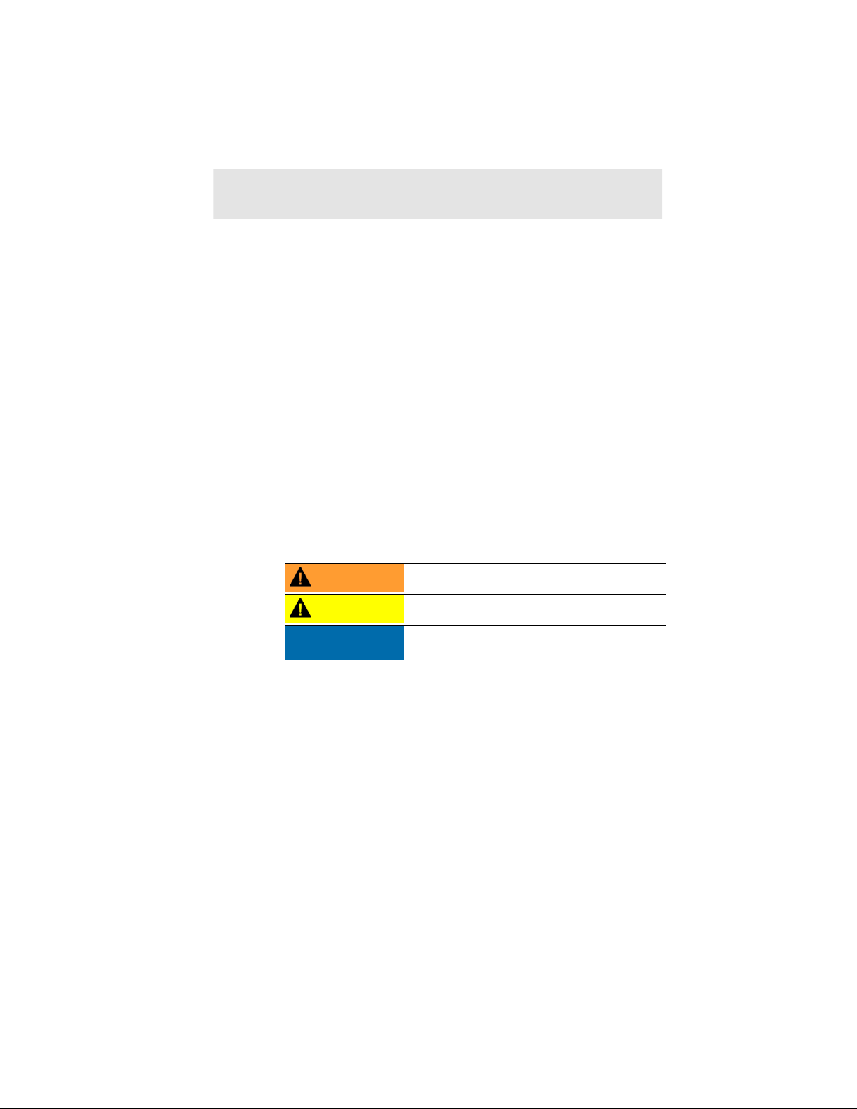
Warnings
Always pay attention to information that is marked by the following
warnings with warning pictograms. Implement the specified
precautionary measures.
WARNING
CAUTION
NOTICE
Indicates potential serious injuries
indicates potential minor injuries
indicates circumstances that may lead to
damage to the products
6
Find Quality Products Online at: [email protected]
www.GlobalTestSupply.com
Page 6
2 Safety and the environment
tation
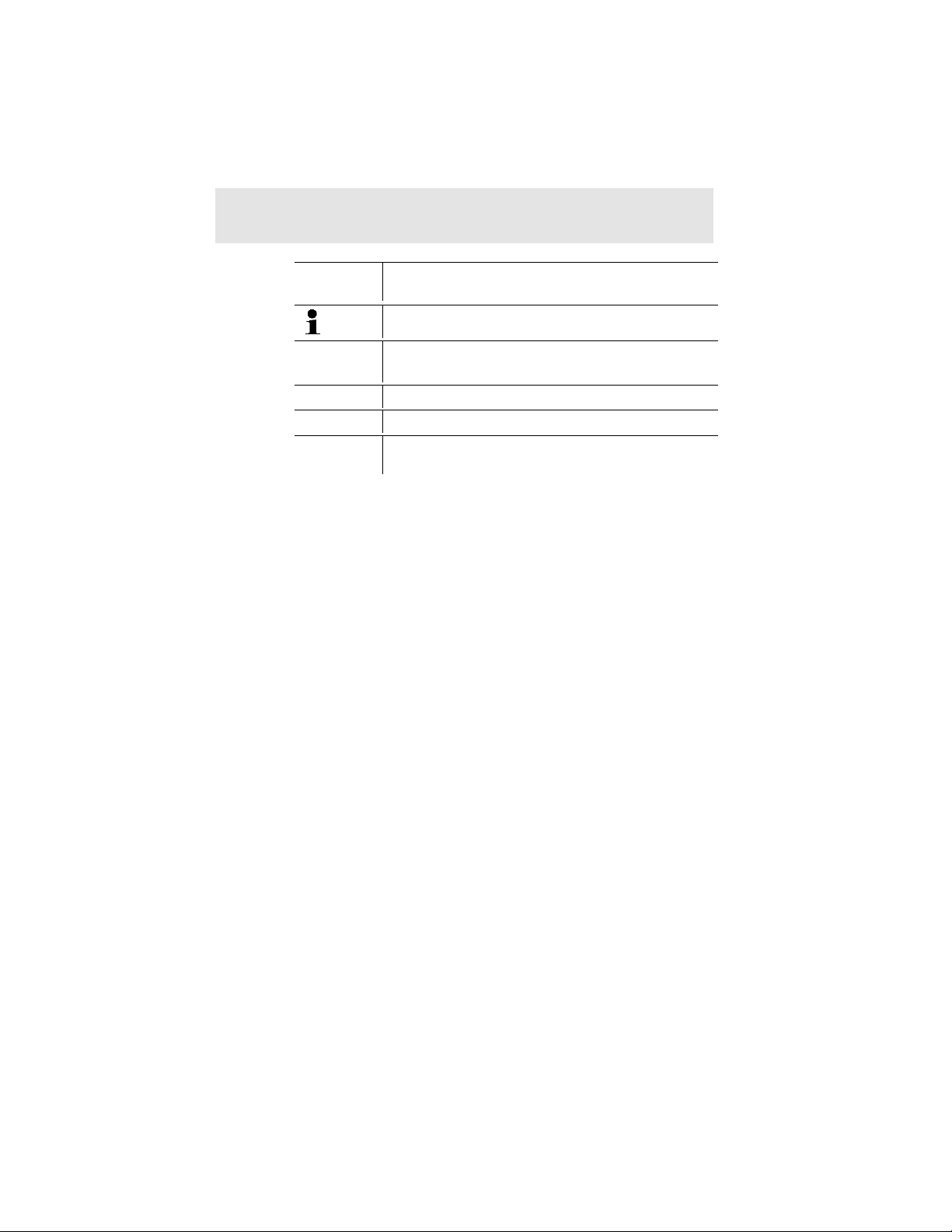
Symbols and writing standards
Represen-
Explanation
Note: Basic or further information.
1. ...
2. ...
> ... Action: a step or an optional step.
- ... Result of an action.
Action: more steps, the sequence must be followed.
[OK] Control keys of the instrument or buttons of the
2.2. Ensure safety
program interface.
> Only operate the product properly, for its intended purpose and
within the parameters specified in the technical data. Do not
use any force.
> Do not operate the instrument if there are signs of damage at
the housing, mains unit or feed lines.
> Do not perform contact measurements on non-insulated, live
parts.
> The flue gas analyzer is not suitable for long-term
measurements and should not be used as a safety (alarm)
instrument.
> Do not store the product together with solvents. Do not use any
desiccants.
> Carry out only the maintenance and repair work on this
instrument that is described in the documentation. Follow the
prescribed steps exactly. Use only original spare parts
from Testo.
> Any further or additional work must only be carried out by
authorised personnel. Testo will otherwise refuse to accept
responsibility for the proper functioning of the measuring
instrument after repair and for the validity of certifications.
> Only use the device in closed, dry rooms and protect it from rain
and moisture.
> Temperatures given on probes/sensors relate only to the
measuring range of the sensors. Do not expose handles and
feed lines to any temperatures in excess of 70 °C unless they
are expressly permitted for higher temperatures.
7
Find Quality Products Online at: [email protected]
www.GlobalTestSupply.com
Page 7
2 Safety and the environment
> The flue gas analyzer must be checked before
commissioning for any visible damage. Do not commission
the flue gas analyzer if there are signs of damage on the
housing, mains unit or supply lines. Electrical risk.
> Dangers may also arise from the systems being measured or
the measuring environment: Note the safety regulations valid in
your area when performing the measurements.
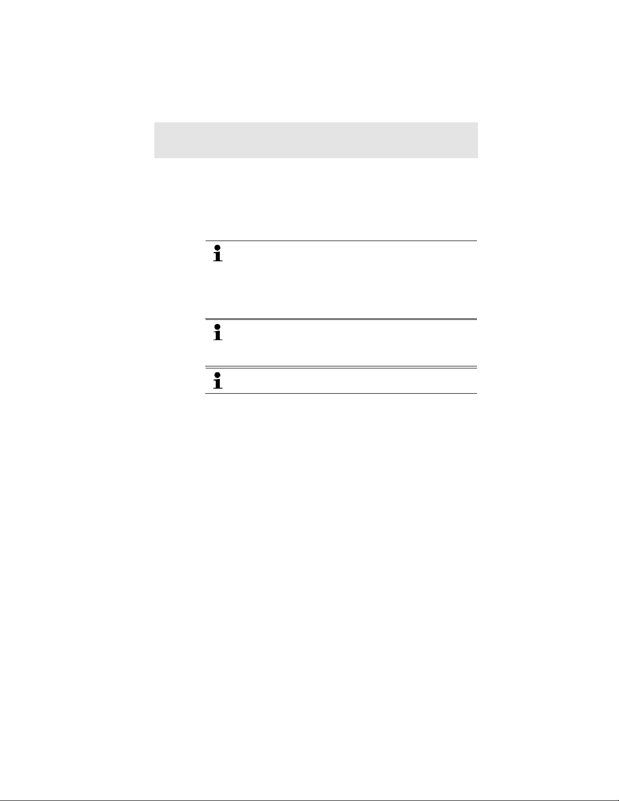
Use distilled water, or alternatively mild solvents such as
isopropanol to clean the flue gas analyzer. If using
isopropanol, please refer to the instruction leaflet for the
product. Isopropanol fumes have a slight narcotic effect,
and typically cause irritation of the eyes and sensitive
mucous membranes. When using it, please ensure that
there is adequate ventilation.
Do not store any objects that have come into contact with
solvents and/or degreasers (e.g. isopropanol) in the case.
Evaporating or leaking solvents and/or degreasers may
cause damage to the instrument and to the sensors.
The use of strong or harsh alcohol or brake cleaner can
result in damage to the instrument.
For products with Bluetooth® (optional)
Changes or modifications that have been made without the explicit
consent of the responsible approval authority, may cause the
retraction of the type approval.
Data transfer may be disturbed by equipment that uses the same
ISM-band, e.g. WLAN, microwave ovens, ZigBee.
The use of radio communication links is not permitted, among
others, in aeroplanes and hospitals. For this reason the following
points must be ensured before entering:
> Switch off the device:
> Isolate the device from any external power sources (mains
cable, external rechargeable batteries, ...).
2.3. Protecting the environment
> Dispose of faulty rechargeable batteries/spent batteries in
accordance with the valid legal specifications.
> At the end of its useful life, send the product to the separate
collection for electric and electronic devices (observe local
regulations) or return the product to Testo for disposal.
8
Find Quality Products Online at: [email protected]
www.GlobalTestSupply.com
Page 8

3 Specifications
3.1. Use
The flue gas analyzer is a handheld measuring device for the
professional flue gas analysis of combustion plants:
• Small combustion plants (burning oil, gas, wood, coal)
The solid fuel measurement adapter (0600 9765) is
required for measurements on solid fuel systems. The
adapter protects the measuring instrument from harmful
substances (dust, organic compounds, etc.).
• Low-temperature and condensing boilers
• Gas water heaters
These systems can be adjusted using the flue gas analyzer and
checked for compliance with the applicable limit values.
The following tasks can also be carried out with the flue gas
analyzer:
• Regulating the O2, CO and CO2 values in combustion plants
for the purpose of ensuring optimal operation.
• Draught measurement.
• Measuring and regulating the gas flow pressure in gas water
heaters.
• Measuring and optimising the flow and return temperatures of
heating systems.
• Ambient CO measurement (only possible with additional
ambient CO probe 0632 3331).
• Ambient CO measurement (only possible with additional
ambient CO probe 0632 1240).
• Detection of CH4 (methane) and C3H8 (propane) (only possible
with additional gas leak probe 0632 3370).
The Bluetooth
is type approved.
®
option may only be operated in countries in which it
3 Specifications
3.2. Technical data
3.2.1. Examinations
As declared in the certificate of conformity, this product complies
with Directive 2014/30/EC.
This product is TÜV-tested in compliance with 1. BImSchV. The
sensors 0393 0105 (CO, H2-compensated), 0393 0003 (O2),
9
Find Quality Products Online at: [email protected]
www.GlobalTestSupply.com
Page 9
3 Specifications
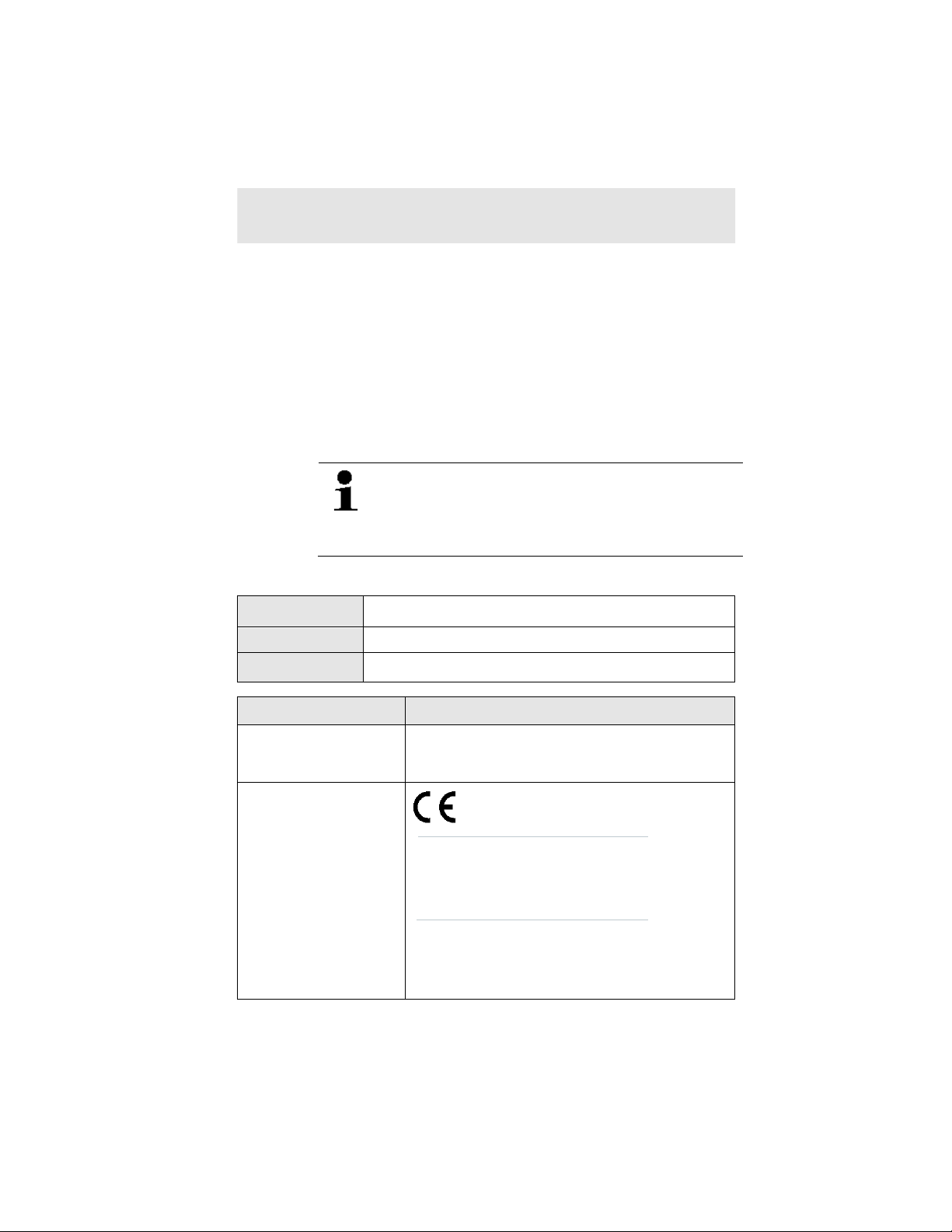
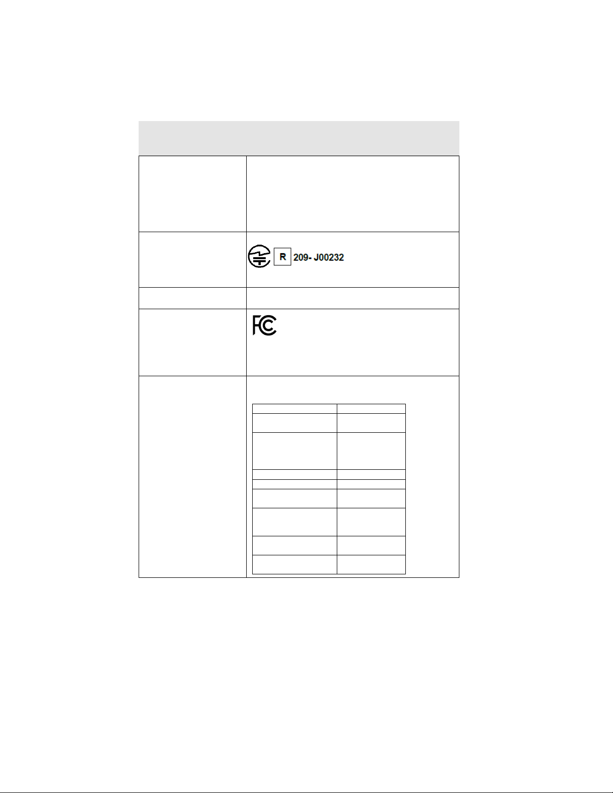
The use of the wireless module is subject to the regulations and
stipulations of the respective country of use, and the module may only be
used in countries for which a country certification has been granted. The
has the obligation to adhere to these regulations
sale, export,
import etc. in particular in countries without wireless permits, is his
responsibility.
Testo 320
0632 3220
23.02.2018
Country
Comments
Canada
contains IC 5123A-WT11U
IC Warnings
Europa + EFTA
The EU Declaration of Conformity
(IE), Italy (IT), Latvia (LV), Lithuania (LT), Luxembourg (LU),
temperature and pressure are TÜV-tested in accordance with EN
50379 part 2.
The measuring cell 0393 0053 (CO, not H2-compensated) is TÜVtested as per EN 50379 part 3.
This product is EMC-tested as per DIN EN 61326-1.
For official measurements in accordance with 1. BImSchV
(chimney sweeps), the measuring instrument must be checked
every six months by a technical testing body of the Guild of Master
Chimney Sweeps or another testing body recognised by the
authorities.
3.2.2. Bluetooth® module (option)
user and every owner
and prerequisites for use, and acknowledges that the re-
3.2.3. Licenses
Product
Mat.-No.
Date
(Länderliste einfügen)
10
can be found on the testo
EU countries:
Belgium (BE), Bulgaria (BG), Denmark (DK), Germany (DE),
Estonia (EE), Finland (FI), France (FR), Greece (GR), Ireland
Find Quality Products Online at: [email protected]
www.GlobalTestSupply.com
Page 10
3 Specifications
Malta (MT), Netherlands (NL), Austria (AT), Poland (PL),
Iceland, Liechtenstein, Norway, Switzerland
Japan
Japan Information
Turkey
Authorized
USA
FCC Warnings
Radio module
Feature
Values
Bluetooth Range
<10 m (free
field)
Bluetooth type
Bluegiga
Module
Qualified Design ID
22298
Declaration ID
B016141
Bluetooth radio
class
Class 1
Bluetooth company
Silicon
Inc.
RF Band
2402 - 2480
MHz
Nominal output
power
17 dBm
Portugal (PT), Romania (RO), Sweden (SE), Slovakia (SK),
Slovenia (SI), Spain (ES), Czech Republic (CZ), Hungary (HU),
United Kingdom (GB), Republic of Cyprus (CY).
EFTA countries:
contains FCC ID: QOQWT11U
WTT11u
Bluetooth
Laboratories
IC Warnings
Find Quality Products Online at: [email protected]
RSS-Gen & RSS-247 statement:
This device complies with Industry Canada licence-exempt RSS standard(s).
Operation is subject to the following two conditions:
(1) this device may not cause interference, and
11
www.GlobalTestSupply.com
Page 11

3 Specifications
(2) this device must accept any interference, including interference that may cause undesired
operation of the device.
Le présent appareil est conforme aux CNR d'Industrie Canada applicables aux appareils radio
exempts de licence.
L'exploitation est autorisée aux deux conditions suivantes :
(1) l'appareil ne doit pas produire de brouillage, et
(2) l'utilisateur de l'appareil doit accepter tout brouillage radioélectrique subi, même si le
brouillage est susceptible d'en compromettre le fonctionnement.
Caution: Radio Frequency Radiation Exposure
This equipment complies with IC radiation exposure limits set forth for an uncontrolled
environment and meets the IC radio frequency (RF) Exposure Guidelines. This equipment should
be installed and operated keeping the radiator at least 20 cm or more away from person´s body in
normal use position.
Co-Location:
This transmitter must not be co-located or operated in conjunction with any other antenna or
transmitter.
Attention : exposition au rayonnement de radiofréquences
Cet équipement est conforme aux limites d'exposition aux radiofréquences IC fixées pour un
environnement non contrôlé et aux Lignes directrices relatives à l'exposition aux radiofréquences
(RF). Cet équipement devrait être installé et utilisé à une distance d'au moins 20 cm d'un radiateur
ou à une distance plus grande du corps humain en position normale d'utilisation.
Co-location
Ce transmetteur ne peut pas être installé en colocation ou être utilisé avec une autre antenne ou
transmetteur, quel qu'en soit le type.
FCC Warnings
Information from the FCC (Federal Communications Commission)
For your own safety
Shielded cables should be used for a composite interface. This is to ensure continued protection
against radio frequency interference.
FCC warning statement
This equipment has been tested and found to comply with the limits for a Class B digital device,
pursuant to Part 15 of the FCC Rules. These limits are designed to provide reasonable protection
against harmful interference in a residential installation. This equipment generates, uses and can
radiate radio frequency energy and, if not installed and used in accordance with the instructions,
may cause harmful interference to radio communications. However, there is no guarantee that
interference will not occur in a particular installation. If this equipment does cause harmful
12
Find Quality Products Online at: [email protected]
www.GlobalTestSupply.com
Page 12

3 Specifications
interference to radio or television reception, which can be determined by turning the equipment
off and on, the user is encouraged to try to correct the interference by one or more of the
following measures:
• Reorient or relocate the receiving antenna.
• Increase the separation between the equipment and receiver.
• Connect the equipment into an outlet on a circuit different from that to which the receiver is
connected.
• Consult the dealer or an experienced radio/TV technician for help.
Caution
Changes or modifications not expressly approved by the party responsible for compliance could
void the user's authority to operate the equipment. Shielded interface cable must be used in
order to comply with the emission limits.
Warning
This device complies with Part 15 of the FCC Rules.
Operation is subject to the following two conditions:
(1) this device may not cause harmful interference, and
(2) this device must accept any interference received,
including interference that may cause undesired operation
Caution: Radio Frequency Radiation Exposure
This equipment complies with FCC radiation exposure limits set forth for an uncontrolled
environment and meets the FCC radio frequency (RF) Exposure Guidelines. This equipment should
be installed and operated keeping the radiator at least 20 cm or more away from person´s body in
normal use position.
.
Japan Information
当該機器には電波法に基づく、技術基準適合証明等を受けた特定
無線設備を装着している。
3.2.4. Declaration of Conformity
You can find the EU declaration of conformity on th
13
Find Quality Products Online at: [email protected]
www.GlobalTestSupply.com
Page 13

3 Specifications
Flue gas loss
0 to 99.9 %
0.1 %
3.2.5. Measurement ranges and resolution
Measurement
parameter
O2 0 to 21 Vol.% 0.1 vol.%
CO 0...4000 ppm 1 ppm
CO, H2-comp.
COlow, H2-comp. 0 to 500 ppm 0.1 ppm
Draught1 -9.99 to 40.00 hPa 0.01 hPa
Fine draught1 -9.999 hPa to
ΔP (only with gas
pressure set 0554
1203)
Fine pressure1
(only with gas
pressure set 0554
1203)
temperature -40 to 1200°C 0.1°C (-40.0 to 999.9°C)
Efficiency 0 to 120 % 0.1 %
Measuring range Resolution
0 to 8000 ppm 1 ppm
+40.000 hPa
0 to 300 hPa 0.1 hPa
0 to 300 hPa 0.01 hPa
0.001 hPa
1°C (from 1000°C)
3.2.6. Accuracy and response time
Measurement
parameter
O2 ±0.2 vol.% < 20 s
CO
1
Depending on the country version
14
Accuracy Response
±20 ppm (0 to 400 ppm)
±5% of meas. val. (401 to 2000
ppm)
±10% of meas. val. (2001 to
4000 ppm)
time (t
< 60 s
)
90
Find Quality Products Online at: [email protected]
www.GlobalTestSupply.com
Page 14

3 Specifications
parameter
time (t90)
pressure set 0554
pressure set 0554
Measurement
Accuracy Response
CO, H2-comp. ±10 ppm or ±10% of meas. val.2
(0 to 200 ppm)
2
±20 ppm or ±5% of meas. val.
(201 to 2000 ppm)
±10% of meas. val. (2001 to
8000 ppm)
COlow, H2-comp. ±2 ppm (0 to 39.9 ppm)
±5% of meas. val.
Draught1 ±0.02 ppm or ±5% of meas. val.
(rest of range)
2
(-0.50 to 0.60 hPa)
± 0.03 hPa (0.61 to 3.00 hPa)
±1.5% of meas. val. (3.01 to
40.00 hPa)
Fine draught1 ±0.02 ppm or ±5% of meas. val.
2
(-0.50 to 0.60 hPa)
± 0.03 hPa (0.61 to 3.00 hPa)
±1.5% of meas. val. (3.01 to
40.00 hPa)
ΔP (only with gas
± 0.5 hPa (0.0 to 50.0 hPa)
±1% of meas. val.
1203)
(50.1 to 100.0 hPa)
±1.5% of meas. val. (rest of
range)
Fine pressure1
(only with gas
1203)
± 0.5 hPa (0.0 to 50.0 hPa)
±1% of meas. val.
(50.1 to 100.0 hPa)
±1.5% of meas. val. (rest of
range)
temperature ± 0.5°C (0.0 to 100.0°C)
±0.5% of meas. val. (rest of
range)
Efficiency - Flue gas loss - -
< 40 s
< 40 s
-
-
depending on
the probe
2
higher value is valid
15
Find Quality Products Online at: [email protected]
www.GlobalTestSupply.com
Page 15

3 Specifications
3.2.7. Other instrument data
Feature Values
Storage and
-20 to 50°C
transport
temperature
Operating
-5 to 45°C
temperature
Ambient humidity
0…90 % rH, not condensing
Power supply Rech. batt.: 3.7 V / 2.4 Ah
Mains unit: 5.0 V/1000 mA
Protection class IP40
Weight 573 g
Dimensions 240 x 85 x 65 mm
Memory 500 measured values
Display Graphic colour display, 240 x 320 pixels
Gas leak testing
probe
Optimum rech. batt.
storage conditions
visual indication (LED)
audible indication by buzzer
Charge level: capacity at 50-80% ambient
temperature: 10-20°C
Battery charge time Approx. 5-6 h with mains unit supplied
Rechargeable
battery life
Approx. 6 h (pump on, 20°C ambient
temperature)
Data transfer IrDA, USB, Bluetooth® (option)
Bluetooth® (option) Range < 10 m
16
Find Quality Products Online at: [email protected]
www.GlobalTestSupply.com
Page 16

4 Product description
4.1. Case 0516 3300 (accessory)
Recommended for stowing away the measuring instrument and
accessories (example)
4.1.1. Bottom level view
4 Product description
1 Sealing clip
2 Flue gas analyser testo 320
3 Repository for printer accessories
• Spare batteries for IRDA printer
• 1 roll of spare thermal paper (0554 0568)
4 Repository for printer
• IRDA printer (0554 0549)
• • Bluetooth
5. Instruction manual
6 Lock testo 320
7 Probes
17
Find Quality Products Online at: [email protected]
www.GlobalTestSupply.com
®
/IRDA printer (0554 0620)
Page 17

4 Product description
• Flue gas probe (e.g. 0600 9741)
• Pitot tube for heating check (0635 2050)
8 Large storage compartment
• Mains unit fortesto 320 (0554 1105)
• Differential temperature set (0554 1208)
• Spare dirt filter (0554 0040)
9 Round storage compartment
• Hose connection set with pressure adapter (0554 1203)
4.1.2. Top level view
1 Soot pump set (0554 0307)
2 Storage compartment
• Fine pressure probe (0638 0330)
3 Storage compartment
• Capillary hose set for fine pressure probe (0554 1215)
• Connecting cable for surface probe (0430 0143)
18
Find Quality Products Online at: [email protected]
www.GlobalTestSupply.com
Page 18

4 Combustion air temperature probe (0600 9787)
5. Surface temperature probe Type K (0604 0994)
4.2. Case 0516 3301 (accessory)
Recommended for stowing away the measuring instrument and
accessories (example)
4.2.1. Bottom level view
4 Product description
1 Fine pressure probe (0638 0330)
2 testo 308 smoke tester (0632 0308)
19
Find Quality Products Online at: [email protected]
www.GlobalTestSupply.com
Page 19

4 Product description
4.2.2. Middle level view
20
1 Sealing clip
2 testo 330-1 /-2 LL flue gas analyzer
3 Repository for printer accessories
• Spare batteries for IRDA printer
• 1 roll of spare thermal paper (0554 0568)
4 Repository for printer
• IRDA printer (0554 0549)
• Bluetooth
®
/IRDA printer (0554 0620)
5. Instruction manual
6 Lock
7 Probes
• Flue gas probe (e.g. 0600 9741)
• Pitot tube for heating check (0635 2050)
8 Large storage compartment
Find Quality Products Online at: [email protected]
www.GlobalTestSupply.com
Page 20

• Mains unit for testo 330-1 /-2 LL (0554 1096)
• Differential temperature set (0554 1208)
• Spare dirt filter (0554 0040)
9 Round storage compartment
• Hose connection set with pressure adapter (0554 1203)
4.2.3. Top level view
4 Product description
1 Soot pump set (0554 0307)
2 Storage compartment
• Fine pressure probe (0638 0330)
3 Storage compartment
• Capillary hose set for fine pressure probe (0554 1215)
• Connecting cable for surface probe (0430 1215)
4 Combustion air temperature probe (0600 9787)
5. Surface temperature probe Type K (0604 0994)
21
Find Quality Products Online at: [email protected]
www.GlobalTestSupply.com
Page 21

4 Product description
[ ]
4.3. Measuring instrument
4.3.1. Front view
1 Display
2 Function keys
3 Keypad
4.3.2. Keypad
Button Functions
Switch measuring instrument on / off
22
Find Quality Products Online at: [email protected]
www.GlobalTestSupply.com
Page 22

Button Functions
Function key (orange, 3x), relevant function is shown on
[esc]
Back, cancel function
[ ]
Icon
Feature
[OK]
Example
[▲] Scroll up, increase value, navigate
[▼] Scroll down, reduce value, navigate
[ ]
4.3.3. Display
4 Product description
the display
Open main menu
Transmit data to the Testo protocol printer.
1 Status bar (dark grey background):
• Warning symbol (only if there is an instrument error,
display of error in instrument diagnosis menu), otherwise:
Instrument designation.
• Symbol (only if data is stored in the temporary memory).
• Display of date and time.
• Indication of Bluetooth
®
status, power supply and remaining
rechargeable battery capacity:
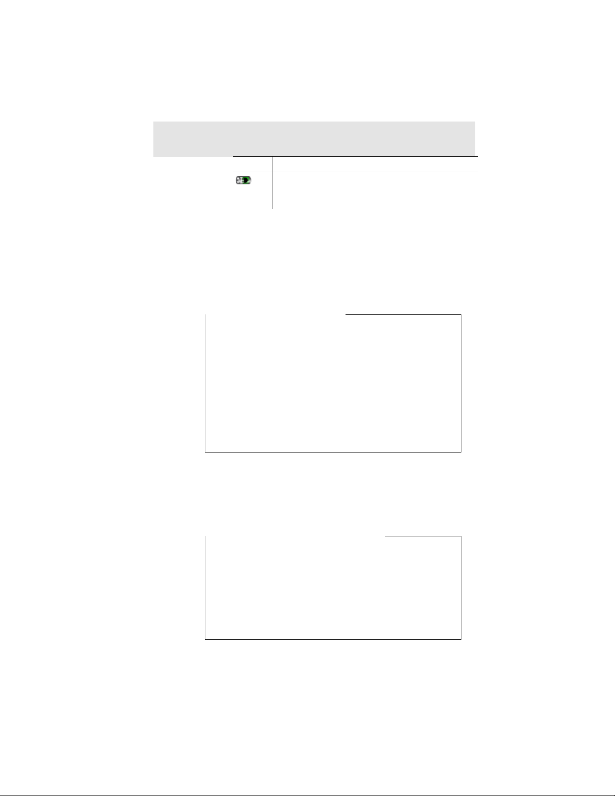
blue symbol = Bluetooth® on,
grey symbol = Bluetooth
Battery operation
®
off
Display of remaining rechargeable battery
capacity by colour and fill level of the battery icon
(green = 5-100%, red = < 5%)
23
Find Quality Products Online at: [email protected]
www.GlobalTestSupply.com
Page 23
4 Product description
Icon Feature
Mains operation
Display of remaining rechargeable battery
capacity: see above
2 Info field of register tabs: Indication of selected
address/location, chosen fuel, chosen measurement type.
3 Selection field for functions (selected function appears against a
white background, unavailable functions are identified by grey
font) or display of measured values.
4.3.4. Instrument connections
4 Function display for function keys.
1 Probe socket
2 Gas outlet
3 Probe socket
4 Micro USB socket (battery charging, data transfer)
4.3.5. Condensate outlet and interfaces
24
Find Quality Products Online at: [email protected]
www.GlobalTestSupply.com
Page 24

1 Infrared interface (IrDA)
2 Bluetooth interface (option)
3 Condensate outlet
4.3.6. Rear view
4 Product description
1 Attachment for carrying strap
2 Condensate trap
3 Magnetic holder
25
Find Quality Products Online at: [email protected]
www.GlobalTestSupply.com
Page 25
4 Product description
WARNING
Magnetic field
May be harmful to those with pacemakers.
> Keep a minimum distance of 15 cm between pacemaker and
instrument.
ATTENTION
Magnetic field
Damage to other devices!
> Keep a safe distance away from products which could be
damaged by the effects of magnetism (e.g. monitors,
computers or credit cards).
4 Service lid
4.3.7. Components
1 Rechargeable battery
26
Find Quality Products Online at: [email protected]
www.GlobalTestSupply.com
Page 26

2 Measured gas pump
3 Slot for O2 sensor
4 Slot for CO sensor, COlow sensor or CO, H2-compensated
sensor
4.4. Compact flue gas probe
1 Removable filter chamber with window and particle filter
2 Probe handle
3 Connector plug for measuring instrument
4 Connecting cable
4 Product description
4.5. Modular flue gas probe
1 Removable filter chamber with window and particle filter
2 Lock release
3 Probe module
4 Connector plug for measuring instrument
5 Probe handle
6 Connecting cable
27
Find Quality Products Online at: [email protected]
www.GlobalTestSupply.com
Page 27
5 First steps
5 First steps
5.1. Commissioning
The measuring instrument is supplied with a rechargeable battery
already fitted.
> Charge the rechargeable battery fully before using the
5.2. Getting to know the product
measuring instrument, see Charging the battery, page 61.
5.2.1. Mains operation
If the mains unit is connected, the measuring instrument is
automatically powered from the unit.
1. Connect the mains unit instrument plug to the instrument's
micro USB socket.
2. Connect the mains plug of the mains unit to a mains socket.
During mains operation the battery is charged
automatically.
5.2.2. Connecting probes
Probe detection at the flue gas socket is carried out
continuously. New probes are recognised automatically.
Connect a probe to the probe socket before switching on
the measuring instrument or start sensor detection
manually after changing the probe: [Options] → Sensor
detection.
Connecting flue gas probes/gas pressure adapters/temperature adapters
28
Find Quality Products Online at: [email protected]
www.GlobalTestSupply.com
Page 28
5 First steps
1201) between measuring instrument and flue gas probe.
> Insert the connector plug into the flue gas socket and lock by
slightly turning it clockwise (bayonet lock).
There must be no more than one extension lead (0554
Connecting other sensors
5.2.3. Switching on
> Press [ ].
- The start screen is displayed (duration: approx 15 s).
- During commissioning, when the instrument is switched on, the
Country version menu is displayed.
Set the country version:
1. Select the country version: [▲], [▼] → [OK].
2. Confirm confirmation request: Yes → [OK]
- The flue gas analyzer switches off.
3. Restart instrument: Press [ ].
- If the voltage supply was interrupted for a longer period: The
Date/time menu opens.
- The gas sensors are zeroed.
- There is an instrument error: The Error diagnosis is displayed.
- The Measurement options menu is displayed.
5.2.4. Calling up the function
1. Select function: [▲], [▼].
- The selected function appears in a frame.
2. Confirm selection: [OK].
- The selected function is opened.
> Insert the connector plug of the probe into the probe socket.
29
Find Quality Products Online at: [email protected]
www.GlobalTestSupply.com
Page 29

5 First steps
5.2.5. Entering values
Some functions require values (numbers, units, characters) to be
entered. Depending on the selected function, the values are
entered either via a list field or an input editor.
List field
1. Select the value to be changed (numerical value, unit): [▲],
[▼], [◄], [►] (depending on the selected function).
2. Press [Edit].
3. Set value: [▲], [▼], [◄], [►] (depending on the selected
function).
4. Confirm the entry: [OK].
5. Repeat steps 1 and 4 as required.
6. Save the entry: [Finished].
30
Input editor
1. Select the value (character) to be changed: [▲], [▼], [◄], [►].
2. Apply value: [OK].
Find Quality Products Online at: [email protected]
www.GlobalTestSupply.com
Page 30

Options:
> Toggle between upper/lower case:
select Ι← ABC→&$/ →Ι: [▲], [▼] → [ABC→&$/].
> Position the cursor in the text:
select Ι← ABC→&$/ →Ι: [▲], [▼] → [Ι←] or [→Ι].
> Delete character before or after the cursor:
select ← next → [▲], [▼] → [←] or [→].
3. Repeat steps 1 and 2 as required.
4. Save the entry: Select ← next → [▲], [▼]
5.2.6. Printing/saving data
Data is printed out via the key [ ]. Data is saved via the Options
menu. The Options menu is accessed via the left function key and
is available in many different menus.
To assign the right function key with the Save function or see
Assigning the right function key, page 36,
Only readings assigned a display field in the measurement view will
be saved / printed out.
The measurement data can be printed out parallel to the
saving process, while a measurement program is running.
To be able to transfer data to a record printer via infrared or
Bluetooth interface, the printer used must be enabled, see Printer,
page 40.
Graph charts can be printed out using the Bluetooth® /
IRDA printer 0554 0620.
5 First steps
→ [Next].
5.2.7. Saving data to the clipboard (temporary memory)
Using the clipboard, measurement results from various
measurement types can be combined to produce a common
record, which can then be printed out (see above). Data is saved to
the clipboard via the Options menu and the Clipboard command.
If there is data in the clipboard, the status bar shows the symbol .
If there is data in the clipboard and the Print command is triggered,
all data in the clipboard will be printed out.
> [Options] → Delete clipboard: Any data saved to the
clipboard is deleted.
5.2.8. Confirming an error message
If an error occurs, an error message is shown on the display.
> Confirming an error message: [OK].
31
Find Quality Products Online at: [email protected]
www.GlobalTestSupply.com
Page 31
5 First steps
Errors that have occurred but have not yet been rectified are
indicated by a warning symbol ( ) in the header.
Error messages that have not yet been cancelled can be displayed
in the Error diagnosis menu, see Instrument diagnosis, page 35.
5.2.9. Switching off
Unsaved measured values are lost if the flue gas analyser
is switched off.
> Press [ ].
- Depending on the instrument status, the pump starts and the
sensors are rinsed until the switch-off thresholds (O
other measurement parameters < 50 ppm) are reached. Rinsing
lasts no more than 3 minutes.
- The measuring instrument switches off.
5.3. Address/Location
All measuring values can be saved under the currently active
location. Measuring values that have not been saved are lost when
the measuring instrument is switched off!
Addresses and locations can be created, edited, copied and
enabled. Addresses and locations (incl. protocols) can be deleted.
Call up function:
> [ ] → Address/Location → [OK].
> 20 %,
2
There are various options for opening address.
1. Edit search setting: [Edit].
2. Select search setting: [▲], [▼] → [OK].
Possible settings:
• Show all: All address/location are displayed.
• Search: A search text only brings up address/location that
contain characteristics of the search text.
• Filter: Individual letters or numbers can be selected. All data
beginning with the relevant letter/number is displayed.
The initial letter is the determining factor for the filter
function, and this can only be selected individually. The
search function can also be used to find a series of
several letters within the address!
3. Carry out search according to search setting: [Search]
32
Find Quality Products Online at: [email protected]
www.GlobalTestSupply.com
Page 32

5 First steps
Show all
1. Select address: [▲], [▼].
2. Show details: [Details].
3. Enable a location: select the location → [OK].
- The location is activated.
> Open measurements menu: press [OK] again.
Search
1. Edit search criteria: [►] → [Edit].
2. Select search criteria: [▲], [▼] → [OK].
Possible options:
• Contact person
• Address
• Town/city
• Postcode
• Street
- The selected criterion is displayed.
3. Call up entry field for search text: [►] or [▼]
> Enter search text → [Finished]
Do not use the special character * as a placeholder.
Filter
1. Edit search criteria: [Edit].
2. Select search criteria: [▲], [▼] → [OK].
Possible options:
• Contact person
• Address
• Town/city
• Postcode
• Street
- The selected criterion is displayed.
3. Enable tab: [▼]
4. Select the required tab: [▲], [▼] and sometimes [◄], [►]→
[Filter].
- The search result for the relevant letter or number is displayed.
Create a new measuring location:
A location is always created under an address.
1. Select the address in which the location is to be created.
33
Find Quality Products Online at: [email protected]
www.GlobalTestSupply.com
Page 33

5 First steps
2. [Options] → New/Location → [OK].
3. Enter values or make settings.
4. Finalise the entry: [Finished].
Other location options:
> [Options] → Edit location: make changes to an existing
location.
> [Options] → Copy location: make a copy of an existing
location in the same address.
> [Options] → Delete location: delete an existing location.
Create new address:
1. [Options] → New address → [OK].
2. Enter values or make settings.
3. Finalise the entry: [Finished].
Other address options:
• Edit address: make changes to an existing folder.
• Copy address: make a copy of an existing folder.
• Delete address: delete an existing folder, including the
locations created therein.
• Delete All addresses: delete all existing folders, including the
locations created in them.
5.4. Measurement records
Call up function:
> [ ] → Measurement records → [OK].
There are various options for opening records. see
Address/Location, page 32.
Displaying a record:
1. Choose the required record from the detailed view.
2. Print [Data].
Printing all records for a location:
1. Select measuring location: [▲], [▼]
2. Start printout: [ ].
- All records for the location are printed out.
Options:
> [Options] → Delete Record: delete the selected record.
34
Find Quality Products Online at: [email protected]
www.GlobalTestSupply.com
Page 34

> [Options] → Delete all Records: delete all saved records for a
location.
5.5. Instrument diagnosis
Important operating values and instrument data are displayed. The
status of the sensors and any instrument errors not yet rectified can
be displayed.
Call up function:
> [ ] → Instrument diagnosis → [OK].
Displaying instrument errors:
> Error diagnosis→ [OK].
- Unrectified errors are displayed.
> Display next/previous error: [▲], [▼].
Displaying sensor diagnosis:
1. Sensor diagnosis → [OK].
2. Select sensor. [▲], [▼].
- The status of the sensor is indicated by a traffic light.
A sensor is able to recover. The sensor status indication
may therefore change from yellow to green or from red to
yellow.
5 First steps
Displaying instrument information
> Device information → [OK].
- Information is displayed.
35
Find Quality Products Online at: [email protected]
www.GlobalTestSupply.com
Page 35
6 Using the product
First steps
6 Using the product
6.1. Performing settings
6.1.1. Assigning the right function key
The right function key can have a function from the Options menu
assigned to it. The menu Options is accessed via the left function
key and is available in many different menus. This assignment is
only valid for the currently opened menu / the opened function.
✓ A menu / function is opened in which the Options menu is
6.1.2. Instrument settings
displayed on the left function key.
1. Press [Options] .
2. Select option: [▲], [▼].
Depending on the menu / function from which the Options menu
was opened, the following functions are available.
3. Assign the selected function to the right function key: Press
[Config. Key].
It is assumed that the contents of the chapter First steps
(see
, page 28) are known.
Calling up a function:
> [ ] → Device Settings.
see First steps, page 28
6.1.2.1. Measurement view
The parameters/units and the display (number of measured values
shown per display page) can be set.
The settings are only valid for the currently chosen measurement
type, which is indicated by the symbol in the info field.
Total overview of selectable measurement parameters and units
(available selection depends on the set country version and
selected measurement type):
Display Measurement parameter
FT Flue gas temperature
AT Combustion air temperature
GT Instrument temperature
36
Find Quality Products Online at: [email protected]
www.GlobalTestSupply.com
Page 36

6 Using the product
Display Measurement parameter
O2 Oxygen
CO2 Carbon dioxide
qA+ Flue gas loss with due consideration of the
calorific value range
η+ Efficiency with due consideration of the calorific
value range
CO Carbon monoxide
COunv Carbon monoxide undiluted
λ Air ratio
COumg Ambient carbon monoxide
CO2um Ambient carbon dioxide
O2ref Oxygen reference
Draught Draught measurement
ΔP Differential pressure measurement
E draught External draught (external micro pressure
probe)
E-ΔP External differential pressure (external micro
pressure probe)
cCO Carbon dioxide reduction
ExAir Air surplus
qA Flue gas loss without due consideration of the
calorific value range
η Efficiency without consideration of the heat
value range
Dew Pt Flue gas dew point temperature
Nett Differential temperature
GI Toxin index
ET qA+ - qA
37
Find Quality Products Online at: [email protected]
www.GlobalTestSupply.com
Page 37

6 Using the product
Parameter
Unit
Altitude
m, ft
Calling up the function:
> [ ] → Device settings → [OK] → Measurement view →
[OK]
Changing the parameter/unit in a line:
1. Select the line: [▲], [▼] → [Edit]
2. Select the parameter: [▲], [▼] → [OK]
3. Select the unit: [▲], [▼] → [OK]
4. Save changes: [OK]
Options:
> [Options] → Number of lines: change the number of
measured values per display page.
> [Options] → Blank line: insert a blank line in front of the
selected line.
> [Options] → Delete line: delete the selected line.
> [Options] → Factory setting: reset the measured value
display to the factory settings.
6.1.2.2. Alarm limits
Alarm limits can be set for several display parameters. An audible
alarm signal is triggered when the alarm limit is reached.
Calling up the function:
> [ ] → Instrument Settings → [OK] → Alarm Limits → [OK]
Switching alarm signals on / off, changing alarm limits:
1. Select function or parameter: [▲], [▼] → [Edit].
2. Set parameter: [▲], [▼] and partly [◄], [►] → [OK].
3. Save changes: [Finished].
> Reset the enabled value to the factory setting: [Standard].
6.1.2.3. Units
The units used for parameters in configuration menus can be set.
Call up function:
> [ ] → Device settings → [OK] → Units → [OK].
38
Adjustable units
Find Quality Products Online at: [email protected]
www.GlobalTestSupply.com
Page 38

Parameter Unit
Pressure mbar, hPa
1. Select the line: [▲], [▼]→ [Edit].
2. Select the unit to be changed: [▲], [▼] → [OK].
3. Confirm the entry: [Finished].
6.1.2.4. Date / time
Date, time mode and time can be set.
Calling up the function:
> [ ] → Instrument Settings → [OK] → Date/Time → [OK]
Setting date/time:
1. Select parameter: [◄], [▲], [▼] → [Edit].
2. Set parameter: [▲], [▼] and partly [◄], [►] → [OK].
3. Save changes: [Save].
6.1.2.5. Energy management
Automatic instrument shutdown (Auto-Off) and switching off of the
display light in battery operation can be set.
Calling up the function:
> [ ] → Instrument Settings → [OK] → Energy Management
→ [OK]
6 Using the product
Making settings:
1. Select function or parameter: [▲], [▼] → [Edit].
2. Set parameter: [▲], [▼] and partly [◄], [►] → [OK].
3. Save changes: [Finished].
6.1.2.6. Display brightness
The intensity of the display illumination can be set.
Calling up the function:
> [ ] → Instrument Settings → [OK] → Display Brightness →
[OK]
Performing settings
> Set parameter: [◄], [►] → [OK].
6.1.2.1. Choose measurement type
Individual measurement types can be shown or hidden. These are
displayed or hidden accordingly under Measurement options.
Call up function:
39
Find Quality Products Online at: [email protected]
www.GlobalTestSupply.com
Page 39
6 Using the product
> [ ] → Device settings → [OK] → Choose measurement
type → [OK].
Show or hide measurement types:
1. Select measurement type: [▲], [▼]
2. Enable / disable measurement type: [ ] (enabled), [ ]
(disabled)
3. Save selection: [Finished].
6.1.2.2. Printer
The headers (lines 1-3) and the footers for the printout can be set.
The printer that is used can be activated.
Calling up the function:
> [ ] → Instrument Settings → [OK] → Printer → [OK]
Activating the printer:
1. Select Printer → [OK].
2. Select the printer: [▲], [▼] → [OK].
- The printer is activated and the menu Printer is opened.
The printer 0554 0543 can only be selected after the
Bluetooth
Bluetooth
®
-interface has been activated, see
®
, page 40.
Configuring the print text:
1. Print text → [OK].
2. Select function: [▲], [▼] → [Edit].
> Enter values for Line 1, Line 2, Line 3 and the Footnote
> Print out system data and/or customer data: [ ]
3. Save the entry: select [Finished].
see Bluetooth
6.1.2.3. Bluetooth®
This menu is only available if the instrument is equipped with
Bluetooth. The Bluetooth module can be switched on / off.The relay
40
can now be tested.
Calling up the function:
> [ ] → Instrument Settings → [OK] → Bluetooth → [Edit].
Making settings:
> Set parameter → [OK].
®
, page 40
Find Quality Products Online at: [email protected]
www.GlobalTestSupply.com
Page 40

6.1.2.4. Language
The menu language can be set. The number of available
languages depends on the activated country version, see Country
version, page 41.
Calling up the function:
> [ ] → Instrument Settings → [OK] → Language → [OK]
Activating the language:
> Select the language → [OK].
see Country version, page 41
6.1.2.5. Country version
Changing the country version may alter the basis for calculation
and therefore also the displayed measurement parameters, fuels,
fuel parameters and calculation formulas.
The selection of the country version influences the menu languages
that can be enabled.
Calling up the function:
> [ ] → Instrument Settings → [OK] → Country Version →
[OK]
This action can be password protected. A password is
specified in the menu Password Protection, see
Password protection, page 42.
Possibly:
> Enter the password: [Enter] → Enter password → [Next] →
[OK].
6 Using the product
Setting the country version:
1. Select the country version: [▲], [▼] → [OK].
2. Confirm the confirmation request: Yes → [OK]
- The system is restarted.
see Password protection, page 42
41
Find Quality Products Online at: [email protected]
www.GlobalTestSupply.com
Page 41

6 Using the product
6.1.2.6. Password protection
The password protection is only valid for functions identified by the
following symbol: or .
Password protection can be activated / deactivated, the password
can be changed.
To deactivate the password protection change the password to
0000 (factory setting).
Calling up the function:
> [ ] → Instrument Settings → [OK] → Password Protection
→ [OK]
Possibly:
> Enter the currently valid password:
[Enter] → Enter password → [Next] → [OK].
Changing the password:
1. [Edit].
2. Enter the new password → [Next].
3. [Edit].
4. Enter the new password again to confirm → [Next].
5. Save changes: [Finished].
6.1.3. Sensor settings
6.1.3.1. O2 reference
The O2 reference value can be set.
The O2 reference value setting may be password protected, see
Password protection, page 42.
Call up function:
> [ ] → Sensor settings → O2 reference → [Edit].
Possibly:
> Enter the password: [Enter] → Enter password → [Next] →
[OK].
Setting the O
> Set value → [OK].
42
reference:
2
Find Quality Products Online at: [email protected]
www.GlobalTestSupply.com
Page 42
6.1.3.2. Sensor protection
WARNING
Protection limits can be set to protect the sensors against overload.
Sensor protection switch-off is available for the CO sensor.
Sensor protection is activated if the threshold is exceeded.
To disable sensor protection, the threshold values must be set to 0
ppm.
Call up function:
> [ ] → Sensor settings → Sensor protection → [OK].
Setting sensor protection thresholds:
1. Select parameter: [Edit].
2. Set value → [OK].
3. Save changes: [Finished].
6.1.3.3. Recalibration/adjustment
The CO sensor can be recalibrated and adjusted.
For recalibration/adjustment, Testo recommends using calibration
adapter 0554 1205 or sending the instrument off to Testo Customer
Service.
If obviously unrealistic measured values are displayed, the
sensors should be checked (calibrated) and, if required,
adjusted.
Adjustments made with low gas concentrations can lead to
accuracy deviations in the upper measuring ranges.
Call up function:
> [ ] → Sensor settings → Recalibration → [OK].
Possibly:
> Enter the password: [Enter] → Enter password → [Next] →
[OK].
- Gas zeroing (30 s).
6 Using the product
Performing recalibration/adjustment:
Dangerous gases
Danger of poisoning!
> Observe safety regulations/accident prevention regulations
when handling test gas.
> Use test gases in well ventilated rooms only.
1. Connect the calibration adapter to the flue gas socket.
43
Find Quality Products Online at: [email protected]
www.GlobalTestSupply.com
Page 43

6 Using the product
2. Enable CO measurement parameter: [OK].
3. [Edit] → Enter the test gas concentration (nominal value).
4. Attach the connecting line of the test gas bottle to the
calibration adapter.
5. Apply test gas to the sensor.
6. Start recalibration: [Start].
7. Apply the target value once the actual value is stable
(adjustment): [OK].
-or-
Cancel (no adjustment): [esc].
8. Save changes: [Finished].
6.1.4. Fuels
The fuel can be selected. The fuel-specific coefficients and limits
can be set.
Call up function:
> [ ] → Fuels → [OK].
In order to maintain the measuring accuracy of the
instrument, the correct fuel must be selected or configured.
Correct representation of measuring results is only
assured if the threshold values for the ideal range of the
corresponding measurement task have been set correctly.
The pre-set threshold values are typical values for the
selected system type and the chosen type of fuel.
44
Activating fuels:
> Select the fuel → [OK].
- The fuel is activated and the main menu is opened.
Setting coefficients:
1. Select the fuel → [Coeff.].
2. Select the coefficients: [Edit].
Possibly:
> Enter the password: [Enter] → Enter password → [Next] →
[OK].
3. Set values → [OK].
4. Save changes: [Finished].
Setting limits:
1. Select limit → [Edit].
2. Set values → [OK].
3. Save changes: [Finished].
Find Quality Products Online at: [email protected]
www.GlobalTestSupply.com
Page 44
6.2. Measuring
6.2.1. Preparing for measurement
The First steps chapter (see First steps, page 28) must
have been read.
6.2.1.1. Testing for leaks
The entire measurement system (probe, condensate trap, hoses
and connections) must be tested for leaks before each
measurement to avoid incorrect measurements due to the
infiltration of external air. Testing is carried out while the pump is
running and may be performed by attaching a compressed balloon
pump. The measurement system is leak-tight if the balloon pump is
not filled with air.
6.2.1.2. Zeroing phases
Measuring the combustion air temperature
If no combustion air temperature probe is connected, during the
zeroing phase, the measured temperature of the flue gas probe is
taken as the combustion air temperature.
The flue gas probe should not be in the flue gas duct
during the zeroing phase.
All dependent parameters are calculated using this value. This
method of measuring combustion air temperature is sufficient for
systems dependent on ambient air.
If a temperature probe is connected, the combustion air
temperature is measured continuously via this probe.
6 Using the product
Gas zeroing
When the instrument is switched on, the measurement menu is
opened and the gas sensors are zeroed.
The flue gas probe must be in fresh air during the zeroing
phase!
Draught/pressure zeroing
The pressure sensors are zeroed when a pressure measuring
function is called up.
The flue gas probe must be in the fresh air during the
zeroing phase / the instrument must not be pressurised
during zeroing.
45
Find Quality Products Online at: [email protected]
www.GlobalTestSupply.com
Page 45

6 Using the product
6.2.1.3. Using flue gas probe
Checking the thermocouple
The thermocouple of the flue gas probe must not lie against the
probe cage.
> Check before use. Bend the thermocouple back if necessary.
Aligning the flue gas probe
The flue gas must be able to flow freely past the thermocouple.
> Align the probe by turning it as required.
The tip of the probe must be in the centre of the flue gas flow.
> Align the flue gas probe in the flue gas duct so that the tip is in
the core current (area of the highest flue gas temperature).
6.2.1.4. Measurement view
Only those measurement parameters and -units that are enabled in
the reading display appear in the reading display, in the saved
measurement records and on record printouts.
> Before carrying out measurements, set up the measured value
display in such a way that the required parameters and units
are enabled, see Measurement view, page 36.
46
Find Quality Products Online at: [email protected]
www.GlobalTestSupply.com
Page 46
6.2.1.5. Setting the location and fuel
measurement
Before carrying out measurements, the location and fuel must be
correctly selected, see Address/Location, page 32
6.2.2. Flue gas
and see Fuels, page 44.
To achieve usable measurement results, the
period of a flue gas measurement should be approx. 3 min
and the measuring instrument should display stable
measuring values.
Call up function:
1. [ ] → Measurement options → [OK] → Flue Gas → [OK].
2. Select the fuel → [OK].
Carrying out the measurement:
1. Start measurement: [ ].
If a separate measurement of CO undiluted has not yet
been carried out, this value is calculated using the
measured values of the flue gas probe and is updated
continuously.
If CO undiluted and/or a draught measurement has already
been carried out separately, the value obtained is applied.
- The measured values are displayed.
2. End measurement: [ ].
6 Using the product
Options
> [Options] → Clipboard: data is saved to the clipboard.
> [Options] → Delete clipboard: any data saved to the clipboard
is deleted.
> [Options] → Save: the measured values are saved in a record.
> [Options] → Fluegas matrix: the measured values are
displayed as a flue gas matrix, see below.
> [Options] → Number of lines: change the number of
measured values per display page.
> [Options] → Recalibrate: the gas sensors are set to zero.
> [Options] → Measurement view: (This function is not available
during a measurement): the measured value display menu is
opened.
47
Find Quality Products Online at: [email protected]
www.GlobalTestSupply.com
Page 47

6 Using the product
Showing the flue gas matrix
This function is only available if the measurement parameter CO
has been activated in the measured value display.
Call up function:
✓ The flue gas function is open.
> [Options] → Fluegas matrix.
Options
> [Options] → Clipboard: data is saved to the clipboard.
> [Options] → Delete clipboard: any data saved to the clipboard
> [Options] → Save: the measured values are saved in a record.
> [Options] → Show numeric value: data is displayed as
> [Options] → System type: (This function is not available
> [Options] → Reset graphic: the displayed graphical values are
> [Options] → Thresholds: (This function is not available during
> [Options] → CO + O2 or CO + CO2: choose which parameter
> [Options] → Measurement view: (This function is not available
3.
is deleted.
numerical values.
during a measurement) Set the system type to be able to
configure the ideal zone (green) of the flue gas matrix, using the
limits pre-configured for each system type.
deleted.
a measurement) Enter limits to be able to configure the ideal
zone (green) of the flue gas matrix.
should be assigned to the x-axis of the display matrix (O2 or
CO2).
during a measurement) Open the measured value display
menu.
6.2.3. Draught measurement
Call up function:
✓ A flue gas probe must be connected.
1. [ ] → Measurement options → [OK] → Draught → [OK].
Carrying out the measurement:
During the zeroing phase, the flue gas probe must be
outside the flue gas duct.
Do not measure for longer than 5 min, as a drift of the
pressure sensor means that the measured values may be
outside the tolerance limits.
48
Find Quality Products Online at: [email protected]
www.GlobalTestSupply.com
Page 48

1. Start measurement: [ ].
- Draught zeroing is carried out.
2. Position the flue gas probe in the hot spot (area of the highest
flue gas temperature).
The display showing the maximum measured flue gas
temperature (AT max) helps when positioning the probe.
- The measured value is displayed.
3. End measurement [ ].
Options:
> [Options] → Clipboard: Data is saved to the clipboard.
> [Options] → Delete clipboard: Any data saved to the clipboard
is deleted.
> [Options] → Save: The measured values are saved in a
record.
> [Options] → Measurement view: (This function is not available
during a measurement): The measured value display menu is
4.
6.2.4. External micro pressure probe
opened.
The following measurements can be performed using the external
micro pressure probe (0638 0330):
• Ext-Draught
• Ext-Delta-P Single meas.
• Ext-Delta Program
• Ext 4Pa-Measurement (only available if Germany country
version is selected)
• Heating Check (only available if Germany country version is
selected)
5.
See instruction manual for external micro pressure probe.
6 Using the product
6.2.5. Average
This function is only available when the Italy country version is
selected.
Call up function:
✓ A flue gas probe or a multi-hole probe (0554 5762) is
connected.
> [ ] → Measurement options → [OK] → Average → [OK].
49
Find Quality Products Online at: [email protected]
www.GlobalTestSupply.com
Page 49

6 Using the product
Options:
> [Options] → Recalibrate: the gas sensors are set to zero.
> [Options] → Addresse/Location: the Address/Location folder
> [Options] → Fuels: select fuel.
> [Options] → Sensor detection: once the probe has been
To calculate the average, a series of 3 measurements are carried
out.
Averaging:
1. Position the flue gas probe in the centre of flow (area of the
2. Start measurements
> First measurement: [ ].
> Second and third measurement: [OK]
- The set measurement parameters, measurement period and
- A signal is sounded after 2 min (recommended measurement
3. End measurements: [ ].
- Once the series of measurements has been carried out, the
> If necessary, scroll through the record: [◄], [►]
4. [Next]
5. Enter checks:
6. End check: [Close]
7.
- The record is saved.
is opened.
changed, start sensor detection manually.
highest flue gas temperature).
measured values are displayed.
period)
record for averaging is displayed.
> Select criterion: [▲], [▼].
> Change value: [Edit] → [▲], [▼] → [OK].
6.2.6. BImSchV
This function is only available when the Germany country version
is selected.
A qA average value measurement can be carried out. For this
purpose the average is determined continuously over a period of 30
s, the measuring cycle takes 1 s. The average values actually valid
at the corresponding time of recording are displayed.
Call up function:
✓ A flue gas probe and a combustion air temperature probe must
be connected.
50
Find Quality Products Online at: [email protected]
www.GlobalTestSupply.com
Page 50
4.
6 Using the product
> [ ] → Measurement options → [OK] → BImSchV → [OK].
> Select the fuel → [OK].
Carrying out the measurement:
1. Start the measurement series: [ ]
Wait for the balancing time, until O
20%.
shows a value below
2
2. [Next].
- The qA measured values (O
, AT, VT) are determined (30 s).
2
- The measurement stops automatically.
- The measured values are displayed and saved automatically in
a record.
3. End measurement: [Close]
or
End measurement and call up draught measurement function:
[Draught - Measuring].
Options:
> [Options] → Clipboard: data is saved to the clipboard.
> [Options] → Delete clipboard: any data saved to the clipboard
is deleted.
> [Options] → Save: the measured values are saved in a record.
> [Options] → Address/Location: the Address/Location folder is
opened.
6.2.7. CO undiluted
Call up function:
✓ A multi-hole probe (0554 5762) should be connected.
> [ ] → Measurement options → [OK] → CO undiluted →
[OK].
Carrying out the measurement:
1. Start measurement: [ ]
- The measured value is displayed.
2. End measurement: [ ]
Options:
> [Options] → Clipboard: data is saved to the clipboard.
> [Options] → Delete clipboard: any data saved to the clipboard
is deleted.
51
Find Quality Products Online at: [email protected]
www.GlobalTestSupply.com
Page 51

6 Using the product
> [Options] → Save: the measured values are saved in a record.
6.2.8. Smoke number/HCT
Calling up the function:
> [ ] → Measurement options → [OK] → Smoke
number/HCT→ [OK].
The parameters Smoke No. and Oil depos. are only
available for oil fuels.
Determine smoke tester no./smoke nos./oil depos. with the smoke pump and enter manually:
1. Select parameter → [Edit].
2. Enter data or values → [OK].
Determine smoke tester no./smoke nos./oil depos. with the smoke tester testo 308 and transmit wirelessly:
- The testo 308 must be in data transfer mode ( lights up).
> [Options] → t308.
- The values recorded by the smoke tester are transferred to the
testo 320.
Entering the heat carrier temperature:
> Heat carrier. → [Edit] → enter value → [OK].
Options:
> [Options] → Clipboard: data is saved to the clipboard.
> [Options] → Delete clipboard: any data saved to the clipboard
is deleted.
> [Options] → Save: the measured values are saved in a record.
> [Options] → Reset values: The entered values are deleted.
6.2.9. Pressure
✓ The gas pressure set (0554 1203) must be connected.
Call up function:
> [ ] → Measurement options → [OK] → Pressure → [OK].
52
Find Quality Products Online at: [email protected]
www.GlobalTestSupply.com
Page 52
6 Using the product
WARNING
Carrying out the measurement:
Dangerous mixture of gases
Danger of explosion!
> Make sure there are no leaks between the sampling point and
the measuring instrument.
> Do not smoke or use naked flames during measurement.
Do not measure for longer than 5 min, as the drift of the
pressure sensor could mean that the measured values are
outside the tolerance limits.
1. Connect the gas pressure set to the probe socket.
2. Start measurement: [ ].
- Pressure zeroing is carried out (system must be unpressurised).
3. Pressurise the system.
- The measured value is displayed
4. End measurement: [ ].
Options:
> [Options] → Clipboard: data is saved to the clipboard.
> [Options] → Delete clipboard: any data saved to the clipboard
is deleted.
> [Options] → Save: the measured values are saved in a record.
> [Options] → Measurement view: (This function is not available
during a measurement): the measured value display menu is
opened.
6.2.10. Differential temperature
✓ The differential temperature set (0554 1208) must be
connected.
Call up function:
> [ ] → Measurement options → [OK] → Differential
temperature → [OK].
Carrying out the measurement:
1. Start measurement: [ ].
- The measured values and the calculated differential
temperature (T1 - T2) are displayed.
2. End measurement: [ ].
53
Find Quality Products Online at: [email protected]
www.GlobalTestSupply.com
Page 53

6 Using the product
Options:
> [Options] → Clipboard: Data is saved to the clipboard.
> [Options] → Delete clipboard: Any data saved to the clipboard
is deleted.
> [Options] → Save: The measured values are saved in a
record.
> [Options] → Measurement view: (This function is not available
during a measurement): The measured value display menu is
opened.
6.2.11. O2 air
✓ An O2 dual wall clearance probe (0632 1260) must be
connected.
Call up function:
> [ ] → Measurement options → [OK] → O2air → [OK].
Carrying out the measurement:
1. Start measurement: [ ].
- The measured value is displayed.
2. End measurement: [ ].
Options:
> [Options] → Clipboard: data is saved to the clipboard.
> [Options] → Delete clipboard: any data saved to the clipboard
is deleted.
> [Options] → Save: the measured values are saved in a record.
6.2.12. Gas flow rate
The function is only available if the chosen fuel is a gas.
Call up function:
54
> [ ] → Measurement options → [OK] → Flowrate → [OK].
Carrying out the measurement:
1. Make a note of the gas meter value.
2. Start measurement: [ ].
3. When the adjusted gas flow is reached: [ ].
- The calculated gas flow rate and the gas burner capacity (in
kW) are displayed.
Find Quality Products Online at: [email protected]
www.GlobalTestSupply.com
Page 54

Options:
CO ambient measurement cannot be done with the external
Cigarette smoke influences the measurement by more than
accuracy of measurement. Frontal flow onto the probe
> [Options] → Clipboard: data is saved to the clipboard.
> [Options] → Delete clipboard: any data saved to the clipboard
is deleted.
> [Options] → Save: the measured values are saved in a record.
> [Options] → Enter Gas Flow: set the gas flow value.
> [Options] → Enter heating value: heating value can be set.
> [Options] → Units setting: the unit for gas flow, heating value,
duration and GasPgr can be changed.
6.2.13. Oil flow
The function is only available if the chosen fuel is an oil.
Calling up the function:
> [ ] → Measurements → [OK] → Oil Flow → [OK].
Performing the measurement:
1. Select the parameters Oil Flow (of the oil nozzle) and Oil
Pressure (no effect on calculation): [▲], [▼] → [Edit].
2. Enter values. [▲], [▼] and partly [◄], [►]→ [OK].
- The calculated oil burner capacity (in kW) is displayed.
Options:
> [Options] → Clipboard: Data are saved to the clipboard
> [Options] → Delete clipboard: Any data saved to the clipboard
is deleted.
> [Options] → Save: The readings are saved in a protocol.
> [Options] → Unit settings: The unit for the oil flow can be
changed (kg/h > gal/h or gal/h > kg/h).
6 Using the product
6.2.14. Ambient CO
This function is not available when the Spain country version is
selected.
✓ A flue gas probe must be connected.
55
Find Quality Products Online at: [email protected]
CO ambient probe.
50 ppm. The breath of a smoker influences the
measurement by about 5 ppm.
When using an ambient CO probe, note that:
The direction of flow of the gas has an effect on the
www.GlobalTestSupply.com
Page 55
6 Using the product
leads to higher measured values. The best measurement
Barometric pressure
Call up function:
> [ ] → Measurement options → [OK] → CO ambient →
Carrying out the measurement:
1. Start measurement: [ ].
- The measurement starts and the measured value is displayed
- An audible alarm signal is triggered when the alarm limit is
2. End measurement: [ ].
3. Confirm the message: [OK].
Options:
> [Options] → Clipboard: data is saved to the clipboard.
> [Options] → Delete clipboard: any data saved to the clipboard
> [Options] → Save: the measured values are saved in a record.
> [Options] → Set alarm limits: the alarm limits menu is opened.
results are achieved when the probe is moved gently
backwards and forwards.
When using the ambient CO probe and the flue gas probe,
note that:
the probe must be in the fresh air (CO-free) during the
zeroing phase!
[OK].
graphically (trend display).
reached.
is deleted.
6.2.15. CO2 ambient
This function is not available when the Spain country version is
selected.
56
✓ An ambient CO2 probe (0632 1240) must be connected.
Call up function:
> [ ] → Measurement options → [OK] → AmbCO2 → [OK].
Carrying out the measurement:
1. Select parameter → [Edit].
In order to obtain correct measured values, it is imperative
to enter the prevailing absolute pressure. This can be
entered directly (Pressure absolute), or it is automatically
calculated when entering Altitude and barometric pressure
(
).
Find Quality Products Online at: [email protected]
www.GlobalTestSupply.com
Page 56
2. Enter values. [▲], [▼] and in some cases [◄], [►] → [OK].
3. Start measurement: [ ].
4. End measurement: [ ].
- The ambient CO2 value is displayed.
Options:
> [Options] → Clipboard: data is saved to the clipboard.
> [Options] → Delete clipboard: any data saved to the clipboard
is deleted.
> [Options] → Save: the measured values are saved in a record.
> [Options] → Alarm limit: the alarm limits menu is opened.
> [Options] → Edit: values for adjustable parameters can be
edited.
> [Options] → Measurement view: (This function is not available
during a measurement) The measured value display menu is
opened.
6.2.16. Leak detection
This function is not available when the Spain country version is
selected.
During gas leak detection, no measurement is carried out, but gas
detection is performed.
✓ A gas leak probe (0632 3330) must be connected.
You must also refer to the documentation that comes with
the gas leak probe.
Call up function:
> [ ] → Measurement options → [OK] → Gas leak detection
→ [OK].
6 Using the product
Carrying out detection:
> Set the gas type to be detected and perform gas leak testing by
following the instructions described in the documentation of the
gas leak probe.
1. Start detection: [ ].
- The gas concentration is displayed, and if it exceeds the limit,
an alarm signal will sound.
Options:
> [Options] → Save: the readings are saved in a record.
> [Options] → Alarm limit: (this function is not available during a
measurement) Adjusting alarm limits.
57
Find Quality Products Online at: [email protected]
www.GlobalTestSupply.com
Page 57

6 Using the product
> [Options] → Alarm signal: (this function is not available during
a measurement) Disable/enable alarm signal.
> [Options] → Zeroing probe: perform zeroing.
> [Options] → Sensor detection: newly inserted sensor is
detected.
6.3. Transferring data
2. End detection: [ ].
6.3.1. Report printer
To be able to transmit data via infrared or Bluetooth interface to a
Testo report printer, the printer to be used must have been
activated, see Printer, page 40.
Printing out data takes place via [Print] or [ ]. The function is only
available if a printout is possible.
Representation of the available characters per line is
limited on the printout. Thus, the unit mg/KWh is
displayed on the printout as mg/k.
6.3.2. PC / Pocket PC
Data transfer to a PC can take place via USB, IrDA or Bluetooth®.
You must also refer to the documentation that comes with the
software.
58
Find Quality Products Online at: [email protected]
www.GlobalTestSupply.com
Page 58
7 Maintaining the product
7 Maintaining the product
7.1. Cleaning the measuring instrument
> If the housing of the measuring instrument is dirty, clean it with
a damp cloth. Do not use any aggressive cleaning agents or
solvents! Mild household cleaning agents and soap suds may
be used.
Use distilled water, or alternatively mild solvents such as
isopropanol to clean the flue gas analyzer. If using
isopropanol, please refer to the instruction leaflet for the
product. Isopropanol fumes have a slight narcotic effect,
and typically cause irritation of the eyes and sensitive
mucous membranes. When using it, please ensure that
there is adequate ventilation.
Do not store any objects that have come into contact with
solvents and/or degreasers (e.g. isopropanol) in the case.
Evaporating or leaking solvents and/or degreasers may
cause damage to the instrument and to the sensors.
The use of strong or harsh alcohol or brake cleaner can
result in damage to the instrument.
7.2. Replacing the rechargeable battery
✓ The measuring instrument must not be connected to a mains
socket via the mains unit. The instrument must be switched off.
Change the rechargeable battery within 2 minutes so that
instrument settings (e.g. date/time) are not lost.
1. Place the measuring instrument on its front.
2. Unscrew, lift up and remove the service cover.
59
Find Quality Products Online at: [email protected]
www.GlobalTestSupply.com
Page 59
7 Maintaining the product
3. Press down on the holder lightly with your fingers. Pull the
retaining clip in the direction of the arrow until the catch is
released. Remove holder.
4. Unplug the plug-in connection from the slot.
5. Carefully pull the retaining clips (1, 2) outwards and push
rechargeable battery up and out of the holder (3).
60
6. Insert the new rechargeable battery in the holder. Make sure
that the plug-in connection cable is routed out of the holder at
the side. Press the rechargeable battery into the holder until the
retaining clips click into place.
7. Plug the new rechargeable battery plug-in connection into the
slot.
8. Insert the holder into the guide rail and slide it in the direction of
the arrow until the holder clicks into place.
9. Refit and close the service cover.
Find Quality Products Online at: [email protected]
www.GlobalTestSupply.com
Page 60

7.3. Charging the battery
The rechargeable battery can only be charged at an ambient
temperature of ±0 to +35°C. If the rechargeable battery has been
completely discharged, the charging time at room temperature with
the testo mains unit is approx. 6 h.
7 Maintaining the product
Charging in the measuring instrument
1. Connect the mains unit instrument plug to the instrument's
micro USB socket.
2. Connect the mains plug of the mains unit to a mains socket.
- The charging process will start. The charging process will stop
automatically when the battery is fully charged.
Battery care
> Do not fully exhaust rechargeable batteries.
> Store rechargeable batteries only in charged condition and at
low temperatures, but not below 0°C (best storage conditions
with a charge level of 50-80%, at an ambient temperature of
10 - 20°C, recharge completely before use).
7.4. Replacing sensors
✓ The measuring instrument must be switched off.
✓ No power supply unit must be plugged in.
1. Place the measuring instrument on its front.
2. Unscrew, lift up and remove the service cover.
3. Disconnect the hose connections from the faulty sensor/bridge.
4. Remove the faulty sensor/bridge from the slot.
5. Install new sensor / new bridge in the slot.
6. Push the hose connections on to the sensor/bridge.
7. Refit and close the service cover.
8. Switch on the measuring instrument.
61
Find Quality Products Online at: [email protected]
www.GlobalTestSupply.com
Page 61
7 Maintaining the product
42.
After replacing an O2 sensor, wait for an equalisation
period of 15 min to elapse before using the instrument
again. (Production of the supply voltage and initial
stabilization phase for new sensors.)
When retrofitting a sensor, the associated measurement
parameter and unit must be enabled, see Sensor settings
page
7.5. Recalibrating/adjusting sensors
See Recalibration/adjustment, page 43.
7.6. Modular flue gas probe
7.6.1. Cleaning the flue gas ducts
✓ Disconnect the flue gas probe from the measuring instrument.
,
1. Release the probe catch by pressing the key on the probe
handle and remove the probe module.
2. Blow compressed air through the flue gas ducts in probe
module and probe handle (see illustration). Do not use a brush!
3. Fit a new probe module on the handle and engage in place.
7.6.2. Replacing the probe module
✓ Disconnect the flue gas probe from the measuring instrument.
62
Find Quality Products Online at: [email protected]
www.GlobalTestSupply.com
Page 62
1. Press the key on the top of the probe handle and remove the
probe module.
2. Plug in the new probe module and engage it in place.
7.6.3. Replacing the thermocouple
1. Release the probe catch by pressing the key on the probe
handle and remove the probe module.
7 Maintaining the product
2. Remove the thermocouple plug-in head from the socket using
a screwdriver and pull the thermocouple out of the probe shaft.
3. Keep inserting the new thermocouple into the probe shaft until
the connection head clicks into place.
4. Fit a new probe module on the handle and engage in place.
7.6.4. Checking the particle filter
> Check the particle filter of the modular flue gas probe regularly
for contamination: check visually by looking through the window
of the filter chamber.
Replace the filter if there are signs of contamination.
63
Find Quality Products Online at: [email protected]
www.GlobalTestSupply.com
Page 63
7 Maintaining the product
7.6.5. Replacing the particle filter:
The filter chamber may contain condensate.
1. Open the filter chamber: turn slightly anti-clockwise.
2. Remove the filter cartridge and replace it with a new one
(0554 3385).
3. Attach the filter chamber and lock it: turn slightly clockwise.
7.7. Compact flue gas probe
7.7.1. Cleaning the probe shaft
✓ Disconnect the flue gas probe from the measuring instrument.
1. Loosen and remove halfshell handles (1).
2. Turn the sealing cap (2) clockwise as far as it will go and
remove probe shaft.
3. Blow compressed air through the probe shaft.
64
Find Quality Products Online at: [email protected]
www.GlobalTestSupply.com
Page 64
4. Replace the probe shaft and lock the sealing cap (2) by tightening
it anti-clockwise (as far as it will go, observe markings).
5. Replace halfshell handles and secure with screws.
7.7.2. Replacing the thermocouple
✓ Disconnect the flue gas probe from the measuring instrument.
1. Loosen and remove halfshell handles (1).
7 Maintaining the product
2. Turn the sealing cap (2) clockwise as far as it will go and
remove probe shaft.
3. Release halfshell elements (3) and remove.
65
Find Quality Products Online at: [email protected]
www.GlobalTestSupply.com
Page 65
7 Maintaining the product
4. Remove the adapter (4) and hose (5), push the thermocouple
out of its holder and disconnect the cable (6) from the
thermocouple.
5. Connect cables to the new thermocouple (white -, green +) (7)
and push the thermocouple back into the holder.
6. Connect the adapter and hose to the thermocouple (8). Adjust
cables and hoses (9), refit halfshell elements.
7. Replace the probe shaft and lock the sealing cap by tightening
it anti-clockwise (as far as it will go, observe markings).
8. Replace halfshell handles and secure with screws.
66
Find Quality Products Online at: [email protected]
www.GlobalTestSupply.com
Page 66

7.7.3. Checking the particle filter
> Check the particle filter of the compact flue gas probe regularly
for contamination:
> Carry out a visual inspection through the window in the filter
chamber.
- Replace the filter if there are any signs of contamination.
7.7.4. Replacing the particle filter
The filter chamber may contain condensate.
7 Maintaining the product
1. Open the filter chamber: turn slightly anti-clockwise.
2. Remove the filter cartridge and replace it with a new one
(0554 0040).
3. Attach the filter chamber and lock it: turn slightly clockwise.
67
Find Quality Products Online at: [email protected]
www.GlobalTestSupply.com
Page 67
7 Maintaining the product
The condensate consists of a weak mix of acids. Avoid skin
pump is in operation.
7.8. Condensate container
The fill level of the condensate container can be read from the
markings on the condensate trap.
Draining the condensate container
contact. Make sure that the condensate does not run over
the housing.
ATTENTION
Damage to the sensors and the flue gas pump due to
condensate entering the gas path!
> Do not empty the condensate container while the flue gas
1. Open the condensate outlet on the condensate trap: Pull out
the plug as far as it will go.
2. Let the condensate run out into a sink.
3. Wipe off any drops still on the condensate outlet with a cloth
and close the condensate outlet.
68
Find Quality Products Online at: [email protected]
www.GlobalTestSupply.com
Page 68

Description
Article no.
The condensate outlet must be completely closed
(marking), otherwise measuring errors could be caused by
8 Tips and assistance
8.1. Questions and answers
infiltrated air.
Question Possible causes/solution
Rechargeable battery low > Switch to mains operation.
Measuring instrument
switches off automatically
or cannot be switched on
Batteries/rechargeable batteries
empty.
> Charge rechargeable battery or
switch to mains operation.
Error message: Cell
protection enabled
The shutdown limit of the CO sensor
was exceeded.
> Remove the probe from the stack.
Error message: Printing
not possible
• With printer 0554 0543: Bluetooth
interface not enabled.
• Wrong printer enabled.
• Printer switched off.
• Printer outside wireless
transmission range.
> Enable Bluetooth interface, see
Bluetooth
> Enable printer to be used.
> Switch on printer.
> Move printer into wireless
transmission range.
8 Tips and assistance
®
, page 40.
8.2. Accessories and spare parts
Printer
Infrared high-speed printer 0554 0549
69
Find Quality Products Online at: [email protected]
www.GlobalTestSupply.com
Page 69

8 Tips and assistance
Description
Article no.
Description Article no.
Bluetooth® /IRDA printer, incl. Mains unit 5 V / 1.0 A
with micro USB cable
Mains unit 5 V / 1.0 A with micro USB cable 0554 1105
Spare thermal paper for printer (6 rolls) 0554 0568
0554 0620
Modular flue gas probes
Description Article no.
Modular flue gas probe 180mm, 500 °C,
0600 9760
thermocouple 0.5 mm, probe shaft diameter: 8 mm
Modular flue gas probe 300 mm, 500 °C,
0600 9761
thermocouple 0.5 mm, probe shaft diameter: 8 mm
Modular flue gas probe 180mm, 500 °C,
0600 9762
thermocouple 0.5 mm, probe shaft diameter: 6 mm
Modular flue gas probe 300 mm, 500 °C,
0600 9763
thermocouple 0.5 mm, probe shaft diameter: 6 mm
Flexible modular flue gas probe, length 330 mm,
0600 9770
Tmax. 180 °C, short-term 200 °C, bending radius
max. 90° for measurements at difficult to access
locations
Compact flue gas probes
Compact flue gas probe 180 mm, 500°C,
0600 9740
thermocouple 1.0 mm, probe shaft diameter: 6 mm
incl. cone
Compact flue gas probe 300mm, 500°C,
0600 9741
thermocouple 1.0 mm, probe shaft diameter: 6 mm
incl. cone
Flexible compact flue gas probe, length 330 mm,
0600 9742
Tmax. 180 °C, short-term 200 °C, bending radius
max. 90° for measurements at difficult to access
locations
70
Find Quality Products Online at: [email protected]
www.GlobalTestSupply.com
Page 70

8 Tips and assistance
Particle filter for compact flue gas probe, 10 pieces
0554 0040
Probe modules/accessories for modular flue gas probes
Description Article no.
Probe shaft module 180mm, 500°C, thermocouple
0554 9760
0.5mm, probe shaft diameter: 8 mm
Probe shaft module 300mm, 500°C, thermocouple
0554 9761
0.5mm, probe shaft diameter: 8 mm
Probe shaft module 180mm, 500°C, thermocouple
0554 9762
0.5mm, probe shaft diameter: 6 mm
Probe shaft module 300mm, 500°C, thermocouple
0554 9763
0.5mm, probe shaft diameter: 6 mm
Probe shaft module 300 mm, 1000°C, thermocouple
0554 8764
1.0 mm, probe shaft diameter: 6 mm
Probe shaft module 700mm, 1000°C, thermocouple
0554 8765
1.0 mm, probe shaft diameter: 6 mm
Spare thermocouple for module 0554 9760,
0430 9760
0554 9762
Spare thermocouple for module 0554 9761,
0430 9761
0554 9763
Spare thermocouple for module 0554 8764 0430 8764
Spare thermocouple for module 0554 8765 0430 8765
Cone, 8mm, steel 0554 3330
Cone, 6mm, steel 0554 3329
Multi-hole probe shaft, length 300 mm, Ø 8 mm, for
0554 5762
CO averaging
Multi-hole probe shaft, length 180 mm, Ø 8 mm, for
0554 5763
CO averaging
Flexible probe shaft module 0554 9770
Hose extension 2.8 m, extension line probe -
0554 1202
instrument
Particle filter for modular flue gas probe, 10 pieces 0554 3385
Probe modules/accessories for compact flue gas probes
Description Article no.
Spare thermocouple for 0600 9740 0430 0383
Spare thermocouple for 0600 9741 0430 0382
71
Find Quality Products Online at: [email protected]
www.GlobalTestSupply.com
Page 71
8 Tips and assistance
Combustion air temperature probe, 190mm
0600 9787
Description
Article no.
Temperature probe
Description Article no.
Combustion air temperature probe, 300mm 0600 9791
Combustion air temperature probe, 60mm 0600 9797
Fast reaction surface sensor 0604 0194
Miniature ambient air sensor 0600 3692
Other probes
Description Article no.
O2 annular gap probe 0632 1260
Gas leak probe 0632 3330
Ambient CO probe 0632 3331
CO2 ambient probe (without connecting cable) 0632 1240
Connecting cable for CO2 ambient probe, 1.5 m 0430 0143
Gas pressure set: Draught path adapter, silicone
0554 1203
hose 4 mm / 6 mm, reducing cones
Smoke tester incl. oil, soot plates, for measuring
0554 0307
soot in flue gas
Spare sensors
72
O2 sensor 0393 0005
CO sensor 0393 0053
CO sensor H2-compensated 0393 0105
COlow sensor 0393 0103
Cases
System case with double floor (height:180 mm) for
0516 3301
instrument, probes and accessories
System case (height: 130 mm) for instrument,
0516 3300
probes and accessories
Find Quality Products Online at: [email protected]
www.GlobalTestSupply.com
Page 72

8 Tips and assistance
Spare rechargeable battery
0515 0046
Other accessories
Description Article no.
Mains unit incl. micro USB cable 0554 1105
Readout adapter for automatic furnaces 0554 1206
Connecting cable instrument / PC 0449 0047
Easyheat (PC configuration software) 0554 3332
Draught set 0554 3150
External micro pressure probe 0638 0330
Set of capillary hoses 0554 1215
Solid fuel measurement module with adapter and
0600 9765
probe shaft with sintered filter
Sintered filter for solid fuel measurement probe shaft 0133 0035
Filter material for condensate trap on solid fuel
0133 0012
measurement adapter
Adhesive kits (x50) for printouts, paper barcode
labels etc.
0554 0116
Straight Pitot tube 0635 2050
ISO Calibration Certificate Flue Gas 0520 0003
8.3. Updating the instrument software
(registration required).
> Unplug the micro USB cable and switch off the flue gas
analyzer.
1. Hold down [▲].
2. Reconnect the micro USB mains cable to the flue gas analyzer,
continue holding down [▲].
- The display shows Firmware update along the bottom edge.
3. Release [▲].
- Your PC recognises the flue gas analyzer as a removable
medium.
73
Find Quality Products Online at: [email protected]
www.GlobalTestSupply.com
Page 73

8 Tips and assistance
4. Copy the new file (ap320rel.bin) to the detected removable
medium.
- On the display the status bar progresses from left to right. This
process may take a few minutes.
- Once the instrument software (firmware) has been updated, the
system will automatically reboot and is ready for use.
5. Disconnect the connecting cable from the flue gas analyzer.
74
Find Quality Products Online at: [email protected]
www.GlobalTestSupply.com
 Loading...