

Page 1
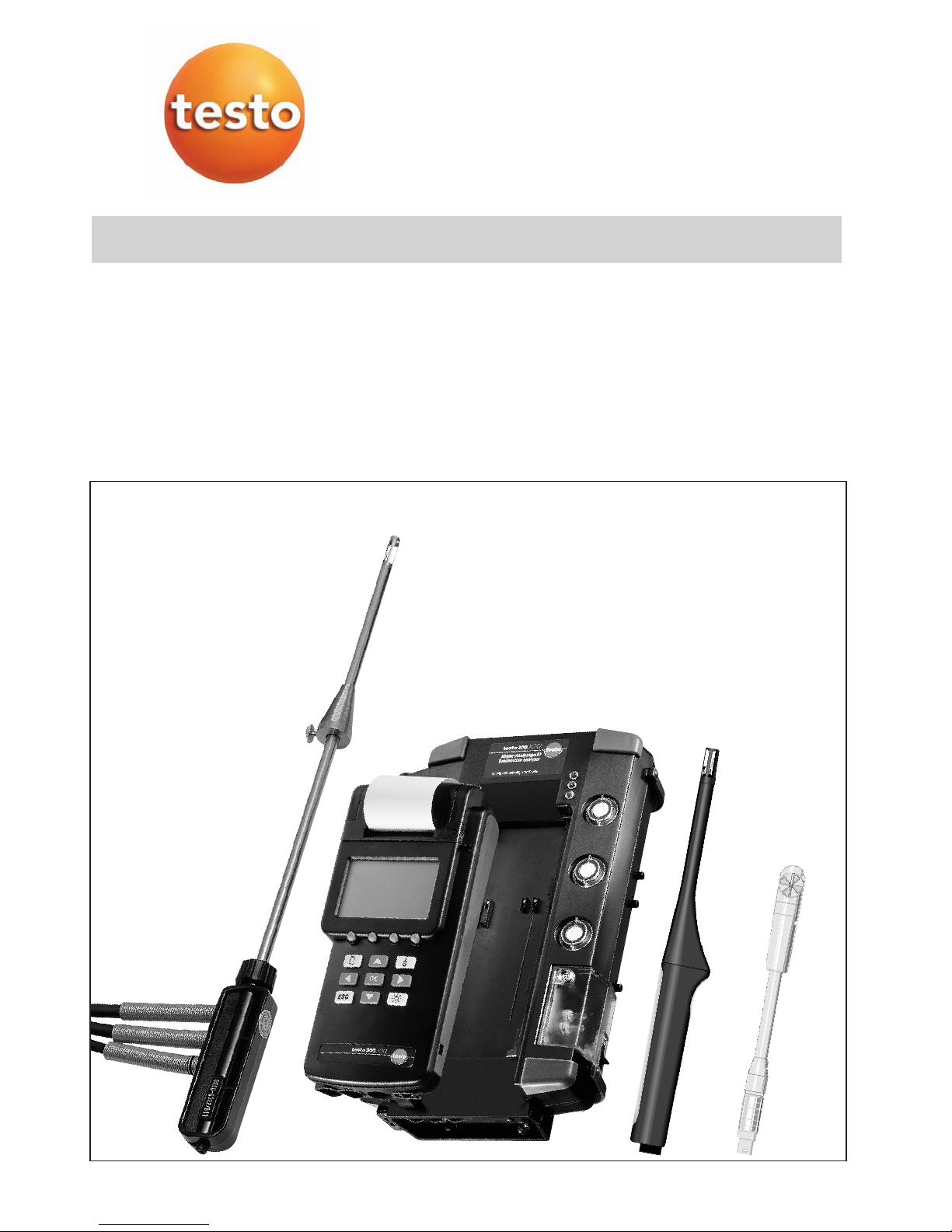
testo 300 XXL
Instruction manual
en
Page 2

Page 3

3
Contents
Page
Contents..........................................................................................................................3
Preface ............................................................................................................................7
Principal safety information ..............................................................................................8
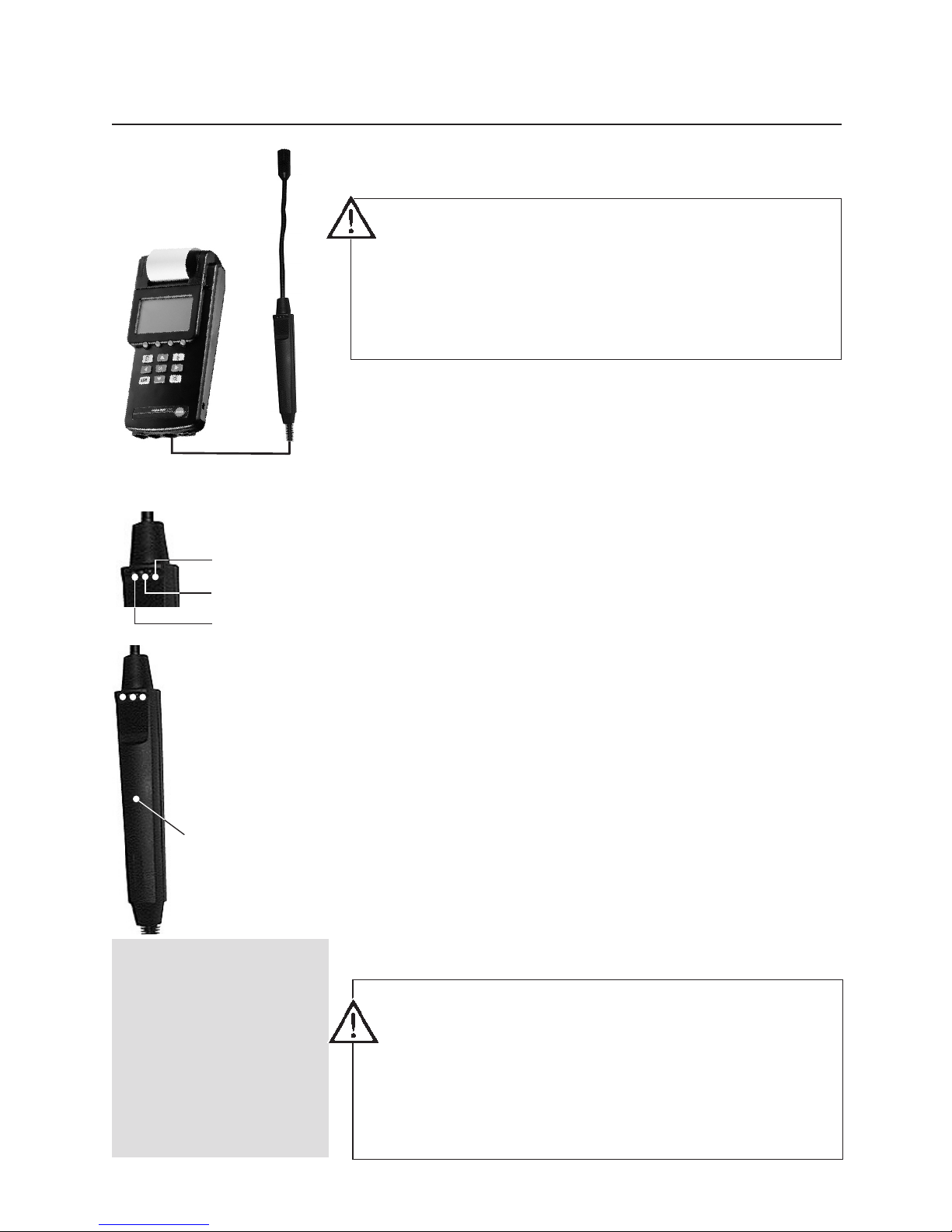
System description 9
Control unit ..............................................................................................................9
Device operation ....................................................................................................10
Touchscreen (option) ..............................................................................................11
Overview of the measuring system..........................................................................12
Menu overview 14
Control unit with analyser box..........................................................................14
Control unit......................................................................................................15
Commissioning ..............................................................................................................16
Function menu and function bar..............................................................................16
Status display of the LED (analyser box)..................................................................17
Power supply ..........................................................................................................18
Power supply, analyser box/control unit ..........................................................18
Mains operation ......................................................................................18
Rechargeable battery operation ..............................................................18
Power supply, control unit................................................................................18
Mains operation ......................................................................................18
Rechargeable battery operation with battery pack ..................................18
Battery operation ....................................................................................18
Rechargeable battery operation with standard batteries..........................18
Charging batteries ..................................................................................................19
Charging batteries, analyser box/control unit ..................................................19
Charging battery pack, control unit..................................................................19
Example measurement ..................................................................................................20
Correct use of the flue gas probe............................................................................20
Preparing for measurements with the control unit and analyser box........................21
Core current search with the control unit and analyser box ....................................22
Flue gas measurement at burners with control unit and analyser box ....................23
Conducting a CO measurement in gas burners
with the control unit and the analyser box ..............................................................24
Draught measurement with the control unit and analyser box ................................25
In compliance with the conformity certificate, the units fulfil the guidelines of
DIN EN 61010-1 safety regulations for electrical devices, control, regulating
and laboratory equipment of guideline 73/23/EEC.
In compliance with the conformity certificate, the unit fulfils the guidelines of
2004/108/EEC.
Page 4

Page
Differential pressure measurement with the control unit ..........................................26
Differential pressure measurement with the control unit ..........................................27
CO measurement with the control unit ....................................................................28
Gas leak probe with control unit..............................................................................29
Humidity measurement with the control unit............................................................30
Velocity measurement with the control unit..............................................................31
Volume measurement in a duct ......................................................................32
Mean value ......................................................................................................33
Volume flow measurement ..............................................................................34
Velocity measurement with the pitot tube ........................................................35
CO
2
measurement with the control unit ..................................................................36
Current/voltage measurement with the control unit ................................................37
Printing ..........................................................................................................................38
Printing the measurement results ............................................................................38
Main menu Memory (analyser box and control unit) ......................................................39
Overview ................................................................................................................39
Saving without selecting a location..........................................................................40
Creating a new location ..........................................................................................41
Selecting saved location..........................................................................................42
Using an existing location as format for a new location ..........................................43
Changing existing location ......................................................................................44
Deleting existing location ........................................................................................45
Barcode pen overview ............................................................................................46
Reading a location with the barcode pen ................................................................47
Reading a location from the measurement menu ....................................................47
Reading several locations with barcode pen from the measurement menu ............47
Displaying saved readings ......................................................................................48
Mean calculation ....................................................................................................49
Printing mean calculation result ..............................................................................50
Deleting entire memory............................................................................................51
Printing saved readings of a location ......................................................................52
Free memory? ........................................................................................................53
Main menu Probe for control unit ..................................................................................54
Scaling ....................................................................................................................54
Resetting ................................................................................................................55
Info..........................................................................................................................55
Main menu Input for control unit ....................................................................................56
Parameters..............................................................................................................56
Temperature ....................................................................................................56
Humidity ........................................................................................................57
Pressure ..........................................................................................................58
Density ............................................................................................................59
Contents
4
Page 5

5
Contents
Page
Pitot tube factor ..............................................................................................60
Cross section ..................................................................................................61
Offset factor ....................................................................................................62
Info ..................................................................................................................62
Alarm limits..............................................................................................................63
Timer ......................................................................................................................63
Main menu Device for control unit ................................................................................64
Changing date/time ................................................................................................64
Setting the date ..............................................................................................64
Setting the time ..............................................................................................66
Auto off ..................................................................................................................66
Printer ....................................................................................................................67
Setting the contrast ........................................................................................67
Entering print text............................................................................................67
Light........................................................................................................................68
Diagnostic ..............................................................................................................68
Units ......................................................................................................................69
Main menu Service for control unit ................................................................................70
Operating values ....................................................................................................70
Resetting factory settings ........................................................................................70
Address ..................................................................................................................70
Device data ............................................................................................................70
Language ................................................................................................................71
Main menu Periphery (with touchscreen only) ................................................................71
Solid fuel measurement option for analyser box ............................................................72
CO measuring ranges in different dilution stages ....................................................73
Main menu Sensors for analyser box and control unit ..................................................73
Recalibration ..........................................................................................................74
NO
2
addition ..........................................................................................................75
Print cal. data..........................................................................................................75
Main menu Input for analyser box and control unit ........................................................76
Spot number index / WTT / oil derivatives ..............................................................76
Fuel ........................................................................................................................77
O
2
rel/CO2max/coefficient ........................................................................................77
Parameters..............................................................................................................79
Pressure ..........................................................................................................79
Pitot tube factor ..............................................................................................80
Cross section ..................................................................................................81
Offset factor ....................................................................................................82
Info ..................................................................................................................83
Dew point AT ..........................................................................................................84
Main menu Device for analyser box and control unit......................................................85
View (display sequence) ..........................................................................................85
Diagnostic ..............................................................................................................86
Page 6

6
Contents
Page
Main menu Service for analyser box and control unit ....................................................87
Operating values ....................................................................................................87
Switching off CO/NO ..............................................................................................88
Device data ............................................................................................................89
Bus address............................................................................................................89
Maintenance ..................................................................................................................90
Inserting new paper roll in printer ............................................................................90
Changing the battery pack ......................................................................................91
Control unit......................................................................................................91
Analyser box....................................................................................................91
Filter change ..........................................................................................................92
Condensation trap ..................................................................................................92
Flue gas probe ........................................................................................................93
Cleaning the flue gas probe ............................................................................93
Cleaning the flue gas probe with gas path closed............................................93
Changing a defective thermocouple ................................................................93
Changing O
2
, CO and NO measuring cells..............................................................94
Installation of CO/NO2 measuring cell ....................................................................94
Installation of NO measuring cell ............................................................................94
Maintenance of the gas pumps ..............................................................................95
Opening the analyser box ................................................................................95
Cleaning the main gas pump and the purging pump ......................................95
Cleaning the main gas pump with optional gas preparation ............................96
Changing the pump cassette of the condensation pump
with optional gas preparation ..................................................................................97
Upgrades ................................................................................................................98
Calculation information ..................................................................................................99
Error messages ..........................................................................................................100
Technical data..............................................................................................................101
Ordering data ..............................................................................................................106
Notes
Page 7

7
Preface
Dear Testo customer,
Your decision to buy the testo 300 XXL was an excellent choice.
The testo 300 XXL is designed for flue gas analysis and all measurements in
heating systems.
Thousands of customers buy our high-quality products every year. There are at
least 7 good reasons for this:
1) Our price/performance ratio is good. Reliable quality at a fair price.
2) Substantially extended warranty periods up to 2 years – depending on the model.
3) We provide an optimum solution to your measuring tasks with over 40 years of
professional experience.
4) Our high quality standards are confirmed by the ISO 9001 certificate.
5) Of course, our devices also bear the CE label required by the EU.
6) Calibration certificates for all relevant measurements. Seminars, consulting and
calibration on site.
7) We don’t leave you on your own after your purchase.
Page 8

Use the device only in the operating and
measuring ranges specified in “Technical data”.
Use the device only under the conditions and for
the purpose for which it was designed. For this,
particularly observe the safety information and the
technical data.
To prevent damage to the instrumentation and
items under test, suitably trained persons should
only use the equipment.
Observe all local Health and Safety regulations
before operating the test equipment.
Do not make measurements on live components.
Observe the warnings on the control unit and
analyser box!
Magnets of the control unit
The magnets of the control unit can damage EC
cards, telephone cards etc.
Operation with mains adapter
Use only the original mains adapter to operate the
device. Replace damaged mains cable only with
an original mains cable of the manufacturer or
agent (i.e. by authorised service).
Check for leaks
The entire measuring system (probe, condensation
trap, filter, hoses and connections) must be
checked for leaks before each measurement, e.g.
by pushing on a collapsed rubber bladder.
Measuring errors can be caused if external air
infiltrates.
Expose the gas outlet
When measuring, ensure that the gas outlets are
exposed to allow the gas to escape unobstructed.
If this is not the case, the measurement results
can be falsified.
Empty the condensation trap
The condensation trap must only be emptied when
the pump is switched off (the measuring cells are
otherwise in danger of damage)!
Disposing of batteries
The end user is legally required to dispose of all
used batteries in accordance with their country’s
regulations.
Disposing of measuring cells
Storing the analyser in rooms containing solvents,
vapours or gases will damage the measurement
cells e.g. cleaning fluids, polishes, paints, cooking
operations. Protect the device from direct sunlight
and store at temperatures <45°C.
Storing the device
Storing the analyser in rooms containing solvents,
vapours or gases will damage the measurement
cells e.g. cleaning fluids, polishes, paints, cooking
operations. Protect the device from direct sunlight
and store at temperatures <45°C.
Charge the battery before use
Before making the first measurement or after
several days of disuse, fully charge the internal
battery (see menu Service
Operating values). Charge the battery at least
every 4 weeks during longer periods of disuse to
prevent damagingly low discharging.
Changing the configuration
Switch off the device to change the configuration
(e.g. probe change), as the device reads the
probe-specific values when it is switched on.
PC cable connected
When the PC cable is connected, it is impossible
to issue a print command.
Using probes with plug head
Ensure the good contact of probes with plug
heads. Fully tighten the union nut on the probe
handle.
Opening the device
If the device is opened, misused or subjected to
force, the warranty will be voided.
Because the pressure sensor heats up, it is
recommended to wait on the “Warm up” for 15
minutes to achieve the best possible accuracy.
8
Principal safety information
Page 9
System description
Control unit
9
On/off button
Function keys
Function bar
Touchscreen (option)
on the rear:
Contacts to analyser box
Reading display
Device active display
Touchscreen pen
holder
Printer
Reading window
Display lighting
Mains adapter connection
Pressure connection
Probe connection
Cancel/back
PC connection
Main menu display
Status display
Location
Acknowledgement
Cursor keys
Connection of the spiral BUS
cable to the analyser box
Page 10

10
System description
Device operation
The analyser measurement box is controlled, read
and programmed using the control unit.
The operation of the testo 300 XXL is designed so
that the key functions are visible at all times on
the display.
The keypad
The function keys allow rapid changes of the
functions of the device and the overall control of
the measurement. The significance of the function
keys is indicated in the function bar. Not all
function keys are used in every menu. Arrows in
the function bar indicate further accessible
functions in the menu. When the right or
left cursor key is pressed, these additional
functions are displayed and can be activated with
the function key.
With the up /down cursor keys, you
can browse between the reading windows (in the
measurement menu) or select a menu item in a
list. When you have reached the last
window/menu item, the device automatically loops
back to the first window or the first menu item.
With the Browse key, you can branch from
the measurement menu to the main menu or from
a submenu to the measurement menu.
The I/O button switches the device on and off.
With the Cancel key, you can terminate
selected procedures or a chosen selection and exit
submenus. When you exit a submenu, you will
always move one menu window backwards until
you reach the main menu.
With the Acknowledge key, the selection or
the execution of the selected function is accepted.
If the key is pressed in the measurement
menu, the menu “Device selection list” appears.
The menu provides information on which device is
in use. 001=Control unit active, 002=Analyser box
active etc. If an analyser box is connected, this is
indicated automatically in the window when the
device is started.
With the Lighting key , the display lighting
can be switched on and off or the automatic timer
can be started.
The display
The display constantly shows all important
information.
In the Reading/Menu display area, 6 readings
per window are indicated in the measurement
menu. Only three readings are indicated in larger
lettering when the zoom function is used (by
function key).
The function bar indicates the significance of the
individual function keys . Their effects can
change according to the menu. The description of
the function keys changes accordingly on the
display.
The function bar can be assigned as desired to
all functions of the function menu. When the key
is pressed together with a function key, the
function menu opens. The entries in the function
menu change according to the connected
components of the measuring system.
The Operation display provides a graphic de-
scription of the current mode of the device, e.g.
whether the pump of the device is running and if
the device is running in mains operation.
The Location box constantly shows whether and
which location hasn’t been selected and is active.
If no location has been selected, “NONAME”
appears on the display.
In the measurement menu, the Reading window
on the right indicates the measured value window
in which you are currently working, e.g. 2/5
indicates that you are working in the second of 5
possible pages.
Errors are indicated on the display as soon as they
occur. The “!” symbol in the status display often
indicates the occurrence of errors.
The touchscreen function (option) allows
direct access to the functions indicated on the
display using a special pen. A brief
touch is sufficient to activate the function.
Page 11

11
System description
Touchscreen (option)
Touch a position on the display with the special
pen. The main menu appears. Each menu item
can be accessed and activated with the special
pen. The example shows the individual steps to
set the lighting status of the control unit.
Measurement menu
Measurement menu
Main menu
Change “Device” settings
Change “Device” settings
or
Adjustment menu
Adjust “Light”
Adjust “Light”
Set “On/Off”
Set automatic
PPeerriipphheerryy
PPeerriipphheerryy
Page 12
12
System description
Overview of the measuring system
Measuring cell heater
protects against
destruction by
condensation
Gas
connection
DP
measurement
Spiral BUS cable
connection
Flue gas probe
connection
Probe
connection
110/230 V
50/60 Hz
Carrying
handle
Control unit
catch
Contact strips to the
control unit
LED status display
Gas path filter
Gas outlet 2
Fresh air inlet filter
Fresh air inlet
Diluting air filter
Gas outlet 1
Condensation tank
Page 13
13
System description
Overview of the measuring system
0
12.1
1.27
92.4
180.1
22.2
BrSt
l
AT °C
VT °C
h %
002
04/06
Noname
Hold
Max
Min
Zoom
Volume flow
rate
measurement
with funnel
Pressure
measurement
Temperature
measuremen
t
CO safety
measurement
Gas leak
measurement
CO
2/humidity
measurement
Current
measurement
Voltage
measurement
Cable connection control
unit/spiral analyser box cable
Control unit
4 user-defined
function keys
Mains connection/
fast battery charge
Integrated differential
pressure measurement
Integrated printer
Multi-probe
input
RS 232
interface
Display
Page 14
14
MEMORY
SENSORS
INPUT
DEVICE
SERVICE
MMaaiinn mmeennuu
Op. values
Switch-off
Device data
Bus address
Display sequence
Units
View
Diagnostic
Spot number/HCT
Fuel
O2rel/CO2max
Parameter
Dewpoint/ambient
Smoke number 1
Smoke number 2
Smoke number 3
Heat carrier temp.
Oil derivative
Info
O2 rel.
CO2max.
coeff.
Temperature VL
Humidity VL Dew
point VL
Pres.
Pitot tube factor
Cross-section
Offset factor
Info
Recal.
NO2 addition
Print cal. data
CO
NO
CO
NO
Read out
Mean value
Fuel meas.
Delete memory
Free memory?
System description
Menu overview
Control unit with analyser box
from height
Absolute
Pres.
Metres above
m.s.l.
Diff. pressure
Duration
No. values
Info
Save
Delete
Duration
Dilution
Info
Save
Delete
Yes
No
Page 15
15
MEMORY
SENSORS
INPUT
DEVICE
SERVICE
PERIPHERY*
MMaaiinn mmeennuu
Op. values
Reset factory
Address
Device data
Lang.
Change date
Auto Off
Printer
Light
Diagnostic
Units
Touchscreen cal.
Set date
°C, °F
m/s, fpm
ppm, %
Off, td°C, g/m3,
g/kg, J/g
m3/h, cfm, m3/m,
m
3
/s, l/s, M3/h
hPa, inW, mbar,
Pa, bar, psi
Parameter
Alarm limits
Timer
Temp.
Humid.
Pres.
Density
Pitot tube factor
Cross-section
Offset factor
Info
CO limit
CO2 limit
dP limit 1
dP limit 2
Acoustic alarm
Duration
No./values
Info
Save
Delete
Circle
Square
Rectangle
Area
from height
absolute
Pressure
Metres above m.s.l.
Diff. pressure
contrast
Print text
On/off
Automatic
Temp.
Humid.
Velocity
Vol.-Flow
Pressure
Gas
yes
no
Probe socket 1
min input
max input
min output
max output
Unit
Decimal place
Info
Save
Delete
Scaling
Reset
Info
Read out
Mean
Delete memory
Free memory?
System description
Menu overview
Control unit
Off
5 Min.
10 Min.
....
*with touchscreen option only
Page 16

Function menu and function bar
Commissioning
16
The function bar can be assigned as desired to all functions
of the function menu. Pressing the key with a function
key opens the function menu. The entries in the function
menu change according to the connected components of
the measuring system.
F
UNCTION MENU ANALYSER BOX/CONTROL UNIT
Pump starts. Flue gas measurement runs.
Doubles the character size.
Saves readings.
Differential temperature measurement with 2 probe inputs of
the analyser box.
Graphic display of the temperature during core current
search.
Fine draught with 0.001 hPa resolution.
Starts solid fuel measurement.
Prints readings.
Printer paper line feed.
Re-zeros the measuring cell.
Fresh air purging of the measuring cells.
Starts CO undiluted measurement.
F
UNCTION MENU, CONTROL UNIT
Doubles the character size.
Freezes the current readings.
Shows the highest value during a measurement.
Shows the lowest value during a measurement.
Calculates mean value.
Additional display for volume flow rate measurement.
Displays in metres per second.
Zeros external pressure probe.
Zeros CO probe.
Starts solid fuel measurement.
Analyser box is detected without restarting the
device.
PPSSttaarrtt
uuCCOO oonn
SSttaarrtt
MMeemm..
DDeellttaa TT
CCoorrccuurr
DDrraagghhtt
PPrriinntt
ZZeerroo
GGaass
ZZoooomm
ZZoooomm
HHoolldd
MMiinn
MMaaxx
VVooll
MMeeaann
mm//ss
hhPPaa==00
ppppmm==00
SSeeaarrcchh
SSttaarrtt
LLFF PPrr
Page 17
17
Commissioning
Function menu and function bar
LED 1
LED 2
LED 3
DDeellttaa TT
MMeemm..
ddPP 11
ddPP 22
PPrriinntt
LLFF PPrr
DDiiaagg..
EESSCC
OOKK
TTeesstt
CChhaannggee
EEnndd
IInnffoo
aa AA
<<
Status display of the LED
Saves readings.
T1 + T2, displays differential temperature.
Differential pressure 0 - 80 mbar
Differential pressure 0 - 1000 mbar
Prints readings.
Printer paper line feed
Direct display of all error messages
F
UNCTION BAR
Cursor up (optional with touchscreen)
Cursor down (optional with touchscreen)
Menu exit (optional with touchscreen)
Confirms input (optional with touchscreen).
Set values come into effect
Change
Prints test page.
Accepts settings and closes window.
Upper/lower case switch
Back + deletes 1 character.
Space
Overview of settings
Sets standard values.
Current value comes into effect
CCuurrrr..
LED1 (Power):
Mains operation Green/Permanent
Battery operation (batt. full) Green/Flashing
Battery operation (batt. empty) Red/Flashing
Battery recharging, Off mode Off
LED2 (Status):
Measuring Green/Permanent
Fresh air/Zeroing Green/Flashing
Defect Red/Flashing
LED3 (Battery recharging):
Battery recharging (fast charge) Green, flashing
Batt. full, compensation charge Green, permanent
Page 18

18
Commissioning
Power supply
115/230 V
Mains
adapter
0554.1084
or
or
Plug mains cable into analyser box. The power supply for
the control unit is ensured when
- control unit is connected to the analyser box by the
contact strips
or
- control unit is connected to the analyser box by the spiral
BUS cable
The power supply for the control unit in rechargeable
battery operation is ensured when:
- control unit is connected to the analyser box by the
contact strips
or
- control unit is connected to the analyser box by the spiral
BUS cable
Observe battery capacity.
Ensure correct polarity.
There should always be rechargeable batteries/batteries in
the control unit.
Power supply, analyser box/control unit
Control unit power supply
MAINS OPERATION
Connect mains adapter to the control unit.
MAINS OPERATION
RECHARGEABLE BATTERY OPERATION
RECHARGEABLE BATTERY OPERATION with battery pack
(art. no. 0554.0097)
RECHARGEABLE BATTERY OPERATION WITH STANDARD
BATTERIES
BATTERY OPERATION
Page 19
19
Battery charging
Commissioning
Charging batteries, analyser box/control unit
Charging battery pack, control unit
The battery packs must be installed in the analyser box and
the control unit for charging.
Plug mains cable into analyser box.
Note
The units must be switched off. Charging is impossible
during operation.
The charging of the battery pack for the control unit is
ensured when:
- control unit is connected to the analyser box by the
contact strips
or
- control unit is connected to the analyser box by the
spiral BUS cable.
Charge level displays:
- Analysis box:
Recharging is in progress: Recharging battery LED
flashes green,
Recharging is complete: Recharging battery LED lights
up green
- Control unit: Shows charge level in display.
The battery pack must be installed in the control unit for
charging.
Standard batteries cannot be charged.
Plug mains adapter into the control unit.
Note
The control unit must be switched off. Charging is
impossible during operation.
Charge level display:
- Charge level is shown in display.
115/230 V
Mains
adapter
0554.1084
The end user is legally required to dispose of all used batteries in
in accordance with their country’s regulations.
CChhaarrggiinngg CCoonnttrrooll UUnniitt
CChhaarrggiinngg CCoonnttrrooll UUnniitt
Page 20
20
Example measurement
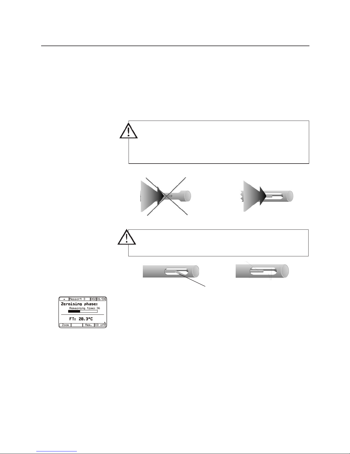
Correct use of the flue gas probe
The measurement of the flue gas temperature is made by
the thermocouple at the tip of the flue gas probe. The probe
tube protects the thermocouple, but has openings in to
allow the stream of flue gas to envelop the thermocouple.
The
temperature
measurement is made during the zeroing phase. The flue
gas probe can be adjusted in the flue at this time (Note: the
AT probe must be connected). This makes it possible to
conduct a core current search during the zeroing phase. The
temperature measured by the flue gas probe is interpreted
by the testo 300 XXL as the combustion air temperature
unless a AT probe is connected (Note: the probe must be
removed from the flue). When the zeroing phase has been
completed, this value is saved as the combustion air
temperature value.
All dependent parameters are calculated by this value.
incorrect
Flue gas
stream
Thermocouple
incorrect
correct
correct
The thermocouple must always be exposed to the stream
of flue gas to allow an exact measurement of the flue
gas temperature and thereby a precise determination of
the flue gas losses. It must not be screened by a web of
the probe pipe.
The tip of the thermocouple must not touch the guard. If
necessary, bend the tip of the thermocouple accordingly.
Page 21

Example measurement
21
Preparing for measurement
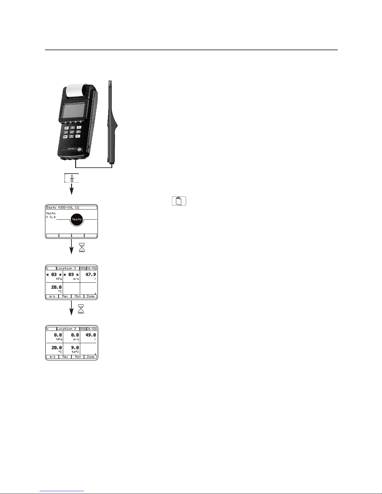
with the control unit and analyser box
Control unit + analyser box + flue gas probe
1 Connect flue gas probe to analyser box.
2 Switch on .
3 Zeroing phase
Any connected CO probe and the gas measuring cells of
the analyser box are zeroed during the zeroing phase.
4 Fuel selection
The menu “Fuel selection” appears during the zeroing
phase.
Select the desired fuel with the keys or and
confirm with .
5. Back to the zeroing phase.
Note
After zeroing phase back to the measurement menu with
the key.
10 sec
Flue gas probe
Analyser box
Initialisation
Zeroing phase
Select the
fuel
Connect the flue gas probe before switching on the control
unit and the analyser box.
Note
The analyser box does not need to be activated in the
device selection menu. It is detected automatically when
the measuring unit starts.
LLooccaattiioonn 33
Page 22
22
Example measurement
Starting core current search:
1 Connect flue gas probe to analyser box.
2 Place flue gas probe in flue pipe.
3 Activate the function menu with the key and one of
the function keys. Select function key with
and confirm with .
4 Start core current search with .
5 Determine core current temperature.
6 Terminate core current search with .
Note
A core current search is also possible during the zeroing
phase.
Corcur
Corcur
Core current search
with the control unit and analyser box
Measurement menu
Measurement menu
Core current menu
Select core current
10 sec
Initialisation
Device zeroing
Automatic fuel display
Zeroing phase
3 x
1 sec
Function menu
CC oo rr ccuu rr
LLooccaattiioonn 33
LLooccaattiioonn 33
Page 23
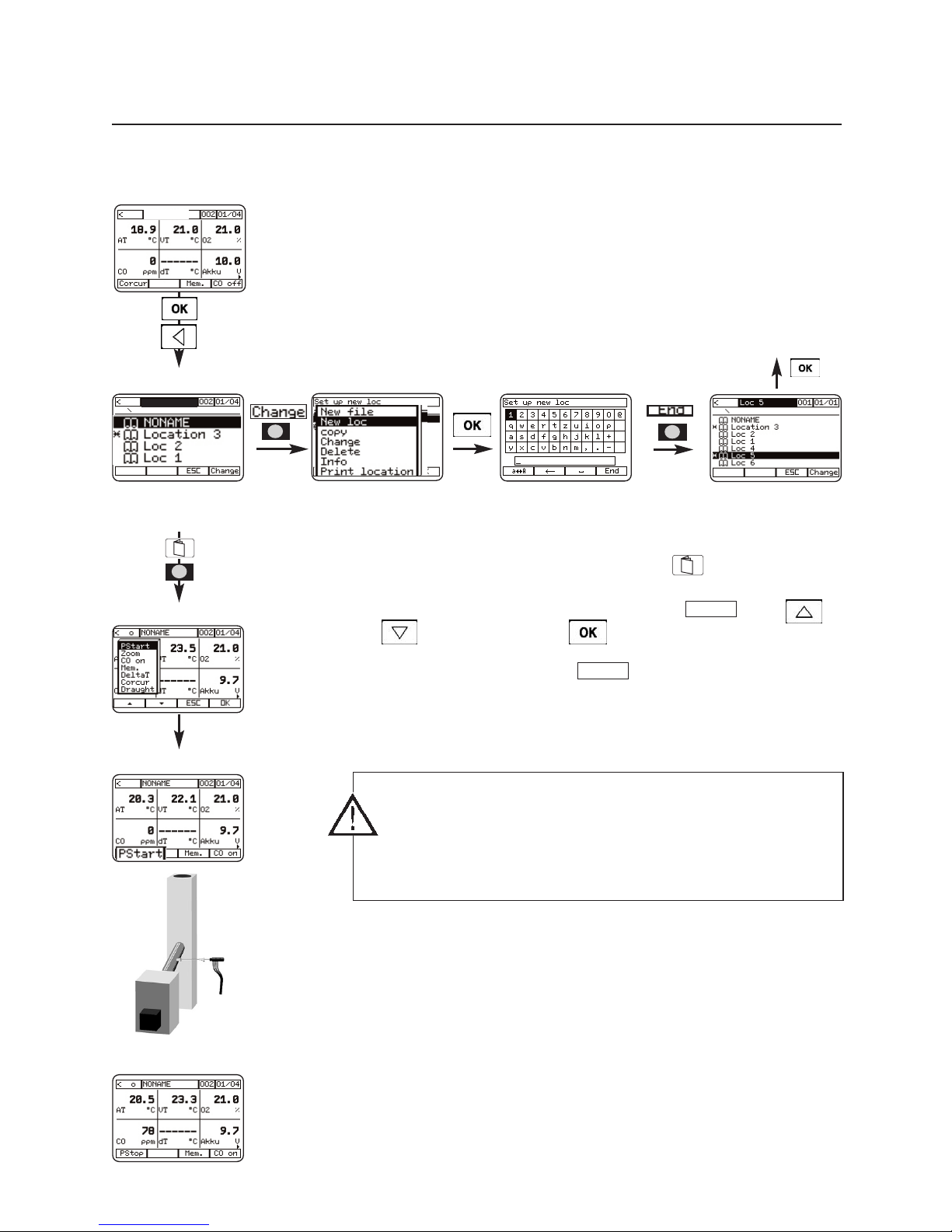
Preparing for measurement
1 Specify new location and select (see page 41):
2 The four function keys of the control unit are freely
configurable with the functions of the function menu.
3 Activate the function menu with the key and one of
the function keys. Select function key with
and confirm with .
4 Start measurement with .
5 Position the flue gas probe in the core current:
Seek flue gas temperature AT max, then fasten the probe
with the cone in this position.
6 When the readings no longer change, stop the pump.
Place flue gas probe in fresh air.
The readings are retained until the pump is next started.
PStart
PStart
Example measurement
Flue gas measurement at burners
with the control unit and the analyser box
23
Back to the measurement menu
If the flue gas probe is positioned vertically or at an angle
of up to 45°, falling drops of condensation can cause a
sudden drop in the temperature.
Remedy: Readjust flue gas probe.
Measurement menu
Location
Measurement menu
Function menu
Measurement menu
Measurement menu
1 sec
Page 24
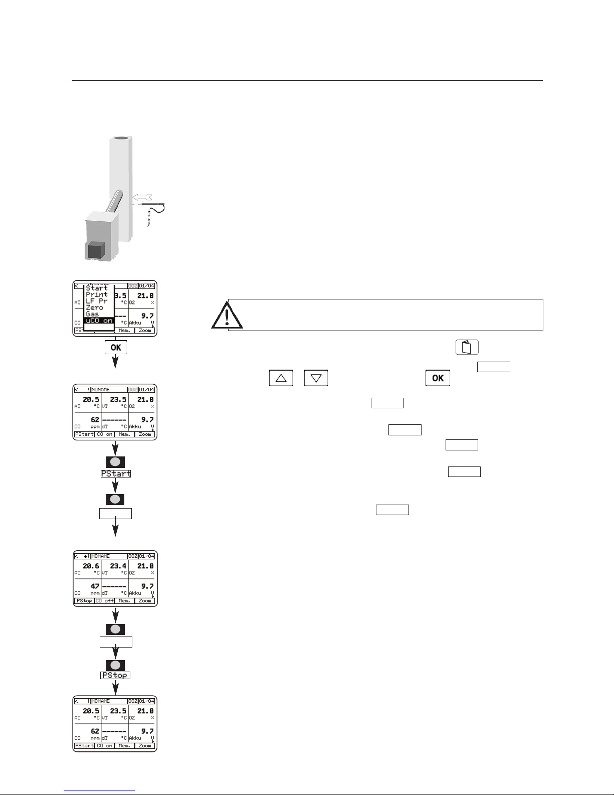
Conducting a CO measurement in gas burners (flue gas path test)
with the control unit and analyser box
1 Activate the function menu with with the key and
one of the function keys. Select function key
with and confirm with .
2 Start measurement with .
3 Measure undiluted CO with .
Display of the function key changes to .
4 Finish undiluted CO measurement with .
Undiluted CO is saved.
5 Finish measurement with .
PStop
uCO off
uCO off
uCO on
PStart
uCO on
uCO off
uCO on
24
Example measurement
Measurement menu
Function menu
Measurement menu
CO limit for the rejection of a system (in relation to
undiluted flue gas): > 1000 ppm uCO
Page 25
Draught measurement
with the control unit and the analyser box
25
Preparing for measurement
Use the flue gas probe for the draught measurement. The
draught measurement can be conducted before or after a
flue gas measurement.
Start measurement
1 Activate the function menu with the key and one of
the function keys. Select function key with
and confirm with .
2 Start measurement with .
3 Place probe in flue.
4 Display of the current reading.
Draught
Draught
Example measurement
A draught measurement is only possible with the pump
switched off. The + pressure inlet of the device must be
open!
Do not change between battery and mains operation
during the draught measurement (voltage fluctuations
influence the result of the measurement)!
If you conduct the draught measurement after a flue gas
measurement, a head of pressure exists in the hose after
the pump has stopped, which must be dispelled. This
occurs within approx. 30 seconds.
Remove any traces of condensation in the flue gas probe
(shake out the probe with the tip towards the floor).
Sensor zeros automatically, probe must be outside
the flue.
Negative sign indicates vacuum,
positive sign indicates pressure in the flue.
Select “Draught”
Measurement menu
Flue gas probe
outside flue
Place probe in flue
Stable reading?
Autom. zeroing
Result
Measurement menu
Function menu
1 sec
DDrrgghhtt
Page 26
Preparing for measurement
Selection of a suitable measuring range.
Two measuring ranges P1 (-80 to +80 hPa) and P2 (-1000
to +1000 hPa) are available in the function menu:
Start measurement
1 Device selection: control unit
2 Activate the function menu with the key and one of
the function keys. Select the function key (low
range) or (high range) with and
confirm with .
3 Zero sensor with function key .
4 Start measurement with function key , stop
measurement with function key or the measurement is terminated automatically when the time has
expired (Input menu - Timer).
5 Display and printing of the current reading.
TStop
TStart
dP1
dP2
dP1
26
Differential pressure measurement
with the control unit
Example measurement
Do not use in the main duct!
Ensure that there are no leaks between the sampling
point and the device (escaping gas and atmospheric
oxygen can create an explosive mixture)!
Do not smoke or use naked flames during the
measurement!
Observe the rated pressure of the connections!
Do not exceed the measuring range!
No gas enters the device because an air cushion forms
between the sensor and the gas inlet. The measuring unit
is therefore not protected against explosions.
Measurement menu
Measurement menu
Measurement menu
Function menu
Select “dP1” and/or
“dP2”
Automatic sensor
zeroing
Start measurement
Stop measurement
Print
1 sec
10 sec
dP1
TT SStt aarrtt
TT SStt oopp
01:00 min
00:27 min
Page 27
27
Measurement with control unit + temperature probe
For pure temperature measurement, e.g. supply / return
temperature
The testo 300 XXL control unit has a multi-probe input.
1 Activate the function menu with the key and one of
the function keys. Select the function key
with and confirm with .
2 Measure T1: Press function key .
3 Measure T2: Press function key .
4 Display of the measured differential temperature value
Measurement with control unit + analyser box + 2
temperature probes
Device selection: flue gas measuring box
1 Configure function key with (see above)
2 display of the current value of Temp.1 (probe
connection), Temp.2 (flue gas probe connection) and the
differential temperature.
DeltaT
DeltaT
T2
T1
DeltaT
Differential temperature measurement
with the control unit
Display
Temp. 1
Display
Temp. 2
Before switching on the testo 300 XXL, connect the
temperature probe!
Example measurement
T1 T2
Measurement menu
Differential temperature
Measurement menu
Measurement menu
Function menu
Select “Delta T”
1 sec
DDeellttaa TT
TT 11
TT 22
4499..88
1155..44
3344..44
Page 28
Measurement with: control unit + CO probe
1 - Initialisation - Zeroing of the CO probe (60 sec)
After zeroing, the CO probe is ready for measuring.
2 Open cap.
Note
The direction of flow of the gas to the probe influences
the measuring accuracy! Optimum measurement results
are achieved when the probe is moved gently backwards
and forwards. Frontal flow onto the probe leads to
excessive readings!
3 Close cap after the measurement.
28
CO measurement
with the control unit
Example measurement
Connect probe before switching on the control unit!
Cap must be closed during zeroing (measuring error
otherwise possible).
Open the cap only during the measurement, then replace.
Warning message when adjusted CO value is exceeded
(change limit in Main menu “Input - Alarm limits Æ- CO
limit”).
10 sec
Initialisation
CO probe zeroing
60 sec
Measurement menu
11 0000
Page 29
Explosive and flammable gases, particularly natural gas and
propane, are detected by the gas leak probe even in low
concentrations in the air. For example, suitable for finding
leaks in gas pipes, vessels and equipment.
1 Connect the probe before switching on the
testo 300 XXL.
2 After the device has been switched on, the warming up
phase of the leak detection probe is automatically started
(approx. 30 sec). Green, yellow and red LED, steady
tone.
3 Ready for use
Green LED flashes steadily, steady tone stops.
4 Conduct leak detection:
• When gas escapes, acoustic signal
(ticking) is audible, becoming faster with increasing
concentration.
• When the 1st switching limit (> 200 ppm) is exceeded,
yellow LED flashes.
• When the 2nd switching limit (> 1%) is exceeded, red
LED flashes, steady tone. No readings of the gas leak
probe are indicated in the display.
The power supply of the gas leak probe is provided by the
control unit.
29
Service tip:
The trigger limit is factory
adjusted to 200 ppm
CH4 gas.
The 1st alarm limit can
be finely adjusted in a
range from 0...1000 ppm
(perform in fresh air only).
Example measurement
Gas leak probe
with control unit
Do not use the gas leak probe and testo 300 XXL in
enclosed rooms or facilities in which gases have
accumulated into an explosive mixture.
The use of other electrical equipment is also prohibited.
It must be ensured that the gas concentration does not
exceed 20% LEL.
Duration of measurement with the gas leak probe with fully
charged battery, maximum 2 hours.
Remove the gas leak probe from the device
immediately after the measurement to prevent heavy
battery discharge.
Never leave the gas leak probe connected when charging
the batteries.
red LED
yellow LED
green LED
Trimmer potentiometer
for fine adjustment of
the 1st alarm limit.
Page 30
30
Example measurement
Humidity measurement
with the control unit
Measurement with: combination humidity probe, e.g.
Part no. 0636.9740
1 Connect combination humidity probe to the probe input
of the control unit.
2 Switch on the control unit.
3 Current readings of relative humidity, temperature and
dew point are displayed.
Changing units:
- Press key
- In Main menu - Device - Units – Change unit
A detailed description is contained in chapter Main menu,
Device for control unit - Units.
10 sec
Initialisation
Zeroing
Measurement menu
Page 31

31
Example measurement
Velocity measurement
with the control unit
Special notes on the thermal velocity probe with
direction probe 0635.1041
Fully push down the cap of the probe.
During the measurement, observe the markings of the
probe head and on the telescope. The markings must form
a line.
For velocity measurements with a known
direction of flow, the arrow mark on the probe
head must point in the direction of flow.
For velocity measurements with an unknown
direction of flow, turn the probe 360° around its
axis. Observe the reading. The maximum value
indicates the direction of flow.
Note
Measurement against the direction of the arrow falsifies the
readings by up to 40%.
Page 32

32
Example measurement
Velocity measurement (hot wire or vane)
with the control unit
Volume flow measurement in a duct with 500 mm
diameter with velocity probe.
1 Connect the velocity probe to the probe input of the
control unit.
2 Switch on control unit.
3 Activate the function menu with the key and one of
the function keys. Select the function key
with and confirm with .
4 Enter duct diameter:
- Press key.
- From Main menu – Input – Parameter – Cross section Circle – enter value
5 Accept the value with function key .
6 Return to the measurement menu with .
7 Start measurement with .
VOL
End
Zeroing
10 sec
Initialisation
Measurement menu
Measurement menu
Measurement menu
Measurement menu
VOL
1 sec
20 sec
Select “Vol”
Main menu
Select “Input”
Select “Parameter”
Function menu
Select “Cross section”
Select “Circle”
Value is automatically
saved
Enter value
End
Vol
Page 33

33
Example measurement
Velocity measurement (hot wire or vane)
with the control unit
Mean value
1 Connect the velocity probe to the probe input of the
control unit.
2 Switch on control unit.
3 Activate the function menu with the key and one of
the function keys. Select the function key with
and confirm with .
4 Enter averaging:
- Press function key .
- Select menu and enter value.
5 Accept value with function key and return to the
measurement menu.
6 Start averaging with .
7 End averaging with .
8. Return to the measurement menu with .
ESC
End
Start
End
Mean
Zeroing
10 sec
Initialisation
Measurement menu
Measurement menu
Measurement menu
1 sec
20 sec
Select “Mean”
Select “Timed/Multi-
point”
Start averaging
Calculating mean
value
Mean calculation
result
Function menu
Enter value
End
End
ESC
Start
22..2255
Mean
Page 34

34
Example measurement
Velocity measurement (volume velocity measurement with funnel)
with the control unit
Volume flow measurement at an inducing opening
A volume flow rate funnel is required for volume flow rate
measurement at an inducing opening (grid or cap with
annular gap).
The opening of the funnel must completely cover the grid
(max. 200 x 200 mm with 0554.0400 or max. 350 x
350 mm with 0554.0410).
1 Connect velocity probe, preferably 0635.1041, to the
probe input of the control unit.
2 Switch on control unit.
3 Activate the function menu with the key and one of
the function keys. Select function key with
and confirm with .
4 Enter duct diameter:
- Press key
- From Main menu - Input - Parameter - Cross section -
Circle - enter value 8.82 cm.
5 Accept the value with function key
6 Return to the measurement menu with .
7 Start measurement with .
VOL
End
VOL
Zeroing
10 sec
Initialisation
Measurement menu
Measurement menu
Measurement menu
Measurement menu
1 sec
20 sec
Select “Vol”
Main menu
Select “Input”
Select “Parameter”
Function menu
Select “Cross section”
Select “Circle”
Value is automatically
saved
Enter value
End
Vol
Page 35

35
Example measurement
Velocity measurement (pitot tube)
with the control unit
Velocity measurement with pitot tube
Method 1 (limited):
Connect the pitot tube directly to the pressure inlet of the
control unit. Limitation: Only the pressure value is shown
during the measurement. The values for velocity speed and
volume flow are shown when the measurement is complete.
Method 2:
Use the pitot tube preferably with the pressure probe order
no. 0638.1445 due to the optimum accuracy. Measuring
range up to approx. 40 m/s. An additional channel is also
displayed (hPa, m/s, m
3
/h).
The velocity is calculated automatically by the device from
the pressure difference at the pitot tube.
Note
The pitot tube factor of the standard Testo pitot tubes is
1.00 and need not be changed. Enter the factor 0.67 for
the straight testo pitot tubes. For other pitot tubes, ask the
supplier for the pitot tube factor and store.
1 Connect the pressure probe to the probe input or the
pitot tube to the pressure outlet of the control unit.
2 Switch on control unit.
3 Enter the pitot tube factor:
- Press key
- From Main menu – Input – Parameter – Pitot factor –
Set value
5 Accept the value with function key .
6 Return to the measurement menu with .
End
Select “Parameter”
Main menu
Select “Input”
Select “Pitot factor”
Measurement menu
Value is automatically
saved
Enter value
End
10 sec
5 sec
Initialisation
Zeroing
Measurement menu
Page 36

36
Example measurement
CO2measurement with the control unit
The probe 0632.1240 measures concentrations of 0...9999
ppm.
1 Connect probe, switch on control unit.
2 Warming up phase of the CO2 sensor
3 Display of a reading
4 Enter absolute pressure:
- Press key.
- From Main menu – Input – Parameter – Pressure –
Absolute pressure – Set value
5 Accept the value with function key .
6 Return to measurement menu with .
7 Display of the current reading.
End
The measured CO2 value depends on the absolute
atmospheric pressure. This effect is compensated by the
device internally. For this, enter the absolute pressure of
the location in the main menu. The displayed CO2 value
is automatically compensated to the entered absolute
pressure.
To avoid the effects of the CO2 content of respired air, hold
the probe as far away from your body as possible.
The measuring principle is based on infrared absorption.
This type of probe has a relatively high power
consumption. For long-term measurements, use the
mains adapter and rechargeable batteries.
If sudden changes occur in the concentration, the probe
will require 30 – 60 sec. to adapt to the environment.
Gently waving the probe reduces the adaptation time.
10 sec
30 sec
Initialisation
Measurement menu
Measurement menu
EE nn dd
Warming up phase
Main menu
Select “Parameter”
Select “Pres.”
Select “Absolute”
Enter value
Select “Input”
Measurement with control unit + CO2 probe
Page 37

37
Example measurement
Current/voltage measurement
with the control unit
Measurement with control unit + cable 0554.0007
Currents and voltages are measured with the probe
0554.0007.
These signals can be assigned to a different physical unit.
Example: 0...20 mA are to represent 0...100 %RH when
displayed later.
1 Connect current and voltage cable, switch on control
unit.
2 Enter the physical unit:
- Press key.
- From Main menu - Probe - Scaling- Probe socket 1 Menu min. input, max. input... Set values
- Min. input - - enter 0 -
- Max. input - - enter 20 -
- Min. output - - enter 0 -
- Max. output - - enter 100 -
- Enter unit
- %RH -
- Enter decimal places - .
3 Scaling info
4 Return to the measurement menu with .
5 Display of the current reading.
Main menu
Select “Probe”
Select “Scaling”
Select “min input”
Set value
Display info
Set further values
(see above)
Select “Probe”
socket 1
Measurement menu
10 sec
Initialisation
Measurement menu
EE nn dd
EE nn dd
OO KK
EE nn dd
EE nn dd
EE nn dd
EE nn dd
Page 38

38
Printing
Printing the measurement results
Printout of the currently displayed readings:
1 Activate the function menu with the key and
function key.
2 Configure function key with .
3 With key back to the measurement menu.
4 Press function key .
5 Print.
If no location is active, the printout is made with
“NONAME”.
Print
Print
testo 300 XXL
SN: 000321/D
Smith Ltd.
Manchester
Location: furnace 5
15:01:00 08:20:15
Fuel: Natural gas
10.9 % CO2
0.45 % O2
2348 ppm CO
320 ppm NO
15 ppm NO2
1050 °C Flue gas temp.
32.5 °C Comb. temp.
15.2 m/s Velocity
1.2 % Flue gas loss
Batch 25/2
Date/time
Memory identifier
Fuel
Readings
1 sec
Measurement menu
Function menu
Select print
Measurement menu
Print
Page 39

39
Main menu Memory
Overview
The memory organisation of the testo 300 XXL is designed
such that a so-called “Location” must exist to identify a
saved reading. This location can consist of up to 20
alphanumeric characters.
For example, a location may be:
- the name of the customer
- a customer number or
- the designation of a location.
Several measurements can be saved for each location. This
is possible by pressing the function key
“Mem.”
several
times.
It is also possible to place locations in directories
(see Measurement data processing).
The maximum possible number of measurements depends
on whether each individual measurement is saved with its
own location or all measurements are saved exclusively with
one location.
Page 40

40
Main menu Memory
Saving without selecting a location
Measurement menu
Function menu
Select “Mem.”
Measurement menu
Save under
“NONAME”
Depending on the selected devices, the readings are
saved in the activated component (control unit or
analyser box).
If no location has been chosen after the device was
switched on, data can still be saved. The location
“NONAME” is used for this. This location is the default
setting.
1 sec
Save currently displayed readings
1 Activate the function menu with the key and
function key.
2 Configure function key with .
3 With key to get back to the measurement menu.
4 Press function key .
5 Save.
If no location is active, the data is saved under “NONAME”.
MMeemm..
MMeemm..
MMeemmoorryy
Page 41

1. Change to menu “Location” with key and .
2. Press key
in window “Location”.
3. With keys , select “New loc”
and confirm with key .
4. Enter the location.
5. With function key , the location is accepted in the
“Location” menu.
End
Change
41
Main menu Memory
Creating a new location
Measurement menu
Location
“New loc” selected
Name location
Displays new
location
Measurement menu
Create new location
change
OK
Confirm selected character
with “OK” key.
End
Page 42

42
Main menu Memory
Selecting saved location
1. Change to menu “Location” with key and .
2. Select desired location with keys .
3. Accept with key . Returns to the measuring menu.
4. With the function key
“Mem.”
, the current readings are
saved under the selected location.
This menu item is accessible during the zeroing phase of the
testo 300 XXL.
Measurement menu
Measurement menu
Location
saved location
selected
Page 43

43
Main menu Memory
Using an existing location as format for a new location
Location selected
Select “copy”
Location
1. Change to menu “Location” with key and .
2. Select the location to serve as the source for the copy.
3. Press .
4. Activate the “copy” function. Press . The cursor is
behind the last character of the location.
5. Press function key “Å” to the desired character. The last
character is deleted each time.
6. With keys , , , , select the desired
character (text input) and accept with key .
7. When the location is complete, press function key
, returning to the location list. The newly created
location is displayed.
Branch to the measurement manu with key .
End
Change
Measurement menu
change
Å
“copy” is activated
Renaming a
location
Location renamed
Displays new
location
Measurement menu
End
Confirm
selected
character
with “OK”
key
Page 44

44
Main menu Memory
Changing existing location
Location selected
Select “Change”
Location
1. Change to menu “Location” with key and .
2. Select the location to be changed.
3. Press .
4. Activate the “Change” function. Press function key “OK”.
5. Press function key “Å” to the desired character. The last
character is deleted each time.
6. With keys , , , , select the desired
character (text input) and accept with key .
7. When the location is complete, press function key ,
returning to the location list. The renamed location is
displayed. The changed location is deleted.
Branch to the measurement menu with key .
End
Change
Measurement menu
change
Å
“Change” activated
Changes the
location name
Location renamed
Displays new
location
Measurement menu
End
Confirm
selected
letter with
“OK”
key
Page 45

45
Main menu Memory
Deleting existing location
1. Change to menu “Location” with key and .
2. Select the location to be deleted.
3. Press .
4. Activate “Delete” function. Press function key .
5. Location is deleted.
6. With function key or key back to the mea-
surement menu.
ESC
OK
change
Measurement menu
Select “Delete”
Entry deleted
“Delete” activated
Location selected
Location
Measurement menu
change
Note
s
OOKK
Page 46

46
Main menu Memory
Barcode pen overview
The barcode pen automates the allocation of measurement
data to a location.
If a barcode label is attached on site, this can be read with
the barcode pen.
The barcode pen is connected to the RS-232 socket on the
bottom of the device and can be connected and
disconnected whilst the device is switched on.
Activate the barcode pen by holding the tip of the pen briefly
against a white surface, e.g. the barcode label. Then move
the pen evenly and quickly in direct contact across the
barcode pattern. A correct reading is indicated by a signal
tone.
The location is automatically accepted in the location list of
the testo 300 XXL and is selectzed as the active location. It
is unnecessary to read or manually enter the customer
number of the customer where you are measuring
beforehand with a PC or by hand into the testo 300 XXL.
When you visit a customer whose customer number is not
saved in the device, you can read the number directly on
site by the barcode into the testo 300 XXL. If the location
read by the barcode pen already exists in the testo 300
XXL, this is activated.
Note
Barcodes can be created and decoded with the evaluation
software.
Page 47

47
Main menu Memory
Reading a location with the barcode pen (during the zeroing phase)
You can also enter the location after the expiry of the zeroing
phase.
Reading a location from the measurement menu
Reading several locations with the barcode pen from
measurement menu.
Procedure as described above (simply repeat the
procedure). The location last read is active.
10 sec
Initialisation
Device zeroing
Measurement menu
Measurement menu
Measurement menu
Page 48

48
Main menu Memory
Displaying saved readings
1.Change to menu “Location” with key and .
2.Select location and confirm with key .
3.Press key in the measurement menu.
4.Select “Memory” menu and confirm with key .
5.Activate “Read out” menu with key .
6.Display of the saved readings.
Main menu
Memory menu
Memory menu
Measurement menu
Displays saved
readings
Displays saved
readings
Measurement menu
Location selected
Location
2 x
Page 49

49
Main menu Memory
Mean calculation
Mean value menu
Mean value menu
Activated
Specify length of time
Main menu
Measurement menu
Start Mean
Calculation
1.Press in the measurement menu.
2.Select “Memory” menu and confirm via .
3.Select mean value menu and press .
4.Enter duration of mean calculation. Confirm reading by
clicking on .
5.Enter number of mean calculations. Confirm reading by
clicking on .
6.Information on input values. Mean calculation can be
started by clicking on .
Note:
Mean calculation stops automatically once the specified
length of time has elapsed.
EE nn dd
EE nn dd
EE nn dd
Enter number
EE nn dd
OO KK
OO KK
Information
Automatic Stop
Mean calculation
SS tt aa rrtt
Page 50

50
Main memory Memory
Printing mean calculation result
Main menu
Read out menu
Displaying and selecting
saved readings
1. Start mean calculation
2. To measurement menu after automatic stop.
3.Change to “Main menu” menu by clicking on .
4.Activate “Memory” menu.
3.Select “Read out” sub-menu.
4. Confirm by clicking on .
5.Displays saved readings. Select value which is to be
printed and start printing by clicking on
.
6.Return to measurement menu by clicking on .
Start
Mean calculation
Measurement menu
Automatic stop
Display of selected
values
Prints out data
Return to
measurement menu
PP rr ii nntt
PP rr ii nntt
Example of printout
Page 51

51
Main menu Memory
Deleting entire memory
Main menu
Measurement menu
Measurement menu
Memory menu
Select “Delete
memory”
Select yes
1. Change to menu “Main menu” with key .
2. Activate the “Memory” menu.
3. Select submenu “Delete memory”.
4. Delete memory “Yes/No”
5. Confirm with key .
6. Return to measurement menu via
Page 52

52
Main menu Memory
Printing saved readings of a location
Measurement menu
Measurement menu
Location selected
Select “Print location”
Print location
Location
cc hhaa nngg ee
Location
1. Change to menu “Location” with key and .
2. Select location and activate function key .
3. Select menu “Print location”.
4. Start printing with key .
5. Then return to the measurement menu with key .
CC hhaa nngg ee
Page 53

53
Main menu Memory
free memory?
Measurement menu
Measurement menu
Main menu
Select “Memory”
Select “free
memory?”
Displays free
memory
1. Change to the main menu with key .
2. Activate the “Memory” menu with .
3. Select “free memory?”
4. Display free memory with key .
5. Return to the measurement menu with key .
The menu provides information on the available memory
capacity to save readings.
Page 54

54
Scaling
Select “Probe”
Select “Scaling”
Select “min input”
Set value
Display info
Set further values
(see above)
Select “Probe
socket 1”
Measurement menu
Measurement menu
Currents and voltages are measured with the probe
0554.0007.
These signals can be assigned to a different physical unit.
Example: 0...20 mA are to represent 0...100 %RH when
displayed later.
1 Connect current and voltage cable, switch on control
unit.
2 Enter the physical unit:
- Press key.
- From Main menu - Probe - Scaling- Probe socket 1 Menu “min input.”, “max input”... “Set values”
- Min input - - enter 0 -
- Max input - - enter 20 -
- Min output - - enter 0 -
- Max output - - enter 100 -
- Enter unit
- %RH -
- Enter decimal places -
3 Scaling info
4 Return to the measurement menu with .
EE nn dd
EE nn dd
OO KK
EE nn dd
EE nn dd
EE nn dd
EE nn dd
Main menu Probe
for control unit
Page 55

55
Main menu Probe
for control unit
Info
Information on the entered values for calibration and
scaling.
Resetting
Entered scaling values are reset to the factory settings.
Select “Probe”
Select “Reset”
Probe socket 1
Reset
Measurement menu
Measurement menu
1. Change to the main menu with key .
2. Activate “Probe” menu with .
3. Select “Reset”.
4. Display the probe socket with key . .
5. Press key to reset.
5. Return to the measurement menu with key .
Page 56

56
Current reading
comes into effect
or
Menu: Set humidity value
Parameters
Note
The temperature, relative humidity and absolute pressure
influence the air density at the measuring point. When these
values have been entered, the density is calculated
automatically. The result is composed as follows:
Temperature
Humidity Density
Metres above sea level
Barometric pressure Absolute pressure
Differential pressure
TEMPERATURE
Enter the temperature as a parameter:
1 Connect probe, switch on control unit.
2 Change to the main menu with key .
3 From Main menu – Input – Parameter – select the
“Temp.” menu.
4 Accept the current reading with key or select
“Input temperature” with the cursor keys.
5 With function key , an automatic branch is made
to the menu “Input humidity” or with key back to the
measurement menu.
Main menu Input
for control unit
Measurement menu
Select “Input”
Select “Parameter”
Select “Temp.”
Enter temperature
EE nn dd
EE nn dd
Page 57

57
H
UMIDITY
Enter the humidity as a parameter:
1 Connect probe, switch on control unit.
2 Change to the main menu with key .
3 From Main menu – Input – Parameter – select Humidity
menu.
4 Accept the current reading with key or select
“Input humidity” with the cursor keys.
5 With function key , an automatic branch is made
to the menu “Input barometric pressure” or with key ,
back to the measurement menu.
Main menu Input
for control unit
Select “Humid.”
EE nn dd
Current reading
comes into effect
Menu: Set
pressure value
Enter humidity
EE nn dd
Measurement menu
Select “Input”
Activate “Parameter”
or
Page 58

58
P
RESSURE
Note
The absolute pressure is determined in the measuring
procedure depicted to the side. The absolute pressure
results from
• Altitude pressure (metres above sea level)
This has an annual average at sea level of 1013 mbar. The
higher the location is above sea level, the lower the
pressure.
• Barometric pressure
This has an annual average independent of the altitude
1013 mbar. This pressure can fluctuate from the annual
average by approx. ±20 mbar depending on the weather
(see local barometer display).
• Differential pressure
This is the higher or lower pressure in the duct.
The entry of the absolute pressure (in hPa only; it is
impossible to switch to other units) has an effect on the
pressure-dependent measurement values. These are
automatically compensated by the pressure: for humidity
(g/kg, J/g), CO2 and in all thermal probes!
Enter the pressure as a parameter:
1 Connect probe, switch on control unit.
2 Change to the main menu with key .
3 From Main menu – Input – Parameter – select Absolute
pressure menu.
4 Accept the current reading with key or select
“Input absolute pressure” with the cursor keys.
5 With function key , an automatic branch is made
to the menu “Input density” or with key , back to the
measurement menu.
Main menu Input
for control unit
Select “Pres.”
Enter the absolute
pressure
Select “Absolute”
Menu: Set
density value
EE nn dd
Current reading
comes into effect
or
EE nn dd
Measurement menu
Select “Input”
Activate “Parameter”
Page 59

59
D
ENSITY
Note
Factory setting: 1293 g/m
3
If this value is not changed, this value is used for the
calculation. The individual values are not taken into account.
The temperature, relative humidity and absolute pressure
influence the air density at the measuring point. These
values can be entered.
When these values have been entered, the density is
calculated automatically.
Enter density as a parameter:
1 Connect probe, switch on control unit.
2 Change to the main menu with key .
3 From Main menu – Input – Parameter – select the
“Density” menu.
4 Accept the current reading with key or select
“Input density” with the cursor keys.
5 With function key , an automatic branch is made
to the menu “Input pitot tube factor” or with key ,
back to the measurement menu.
EE nn dd
Main menu Input
for control unit
Select “Density”
Enter the density
Menu: “Set pitot
tube factor”
Measurement menu
Select “Input”
Activate “Parameter”
Current reading
comes into effect
EE nn dd
or
Page 60

60
P
ITOT TUBE FACTOR
Note
The pitot tube factor of the standard Testo pitot tubes is
1.00 and need not be changed. Enter the factor 0.67 for the
straight testo pitot tubes. For other pitot tubes, ask the
supplier for the pitot tube factor and store.
Enter the pitot tube factor as a parameter:
1 Connect probe, switch on control unit.
2 Change to the main menu with key .
3 From Main menu – Input – Parameter – select “Pitot
factor” menu.
4 Accept the current reading or select “Set pitot tube
factor” with the cursor keys.
5 With function key , an automatic branch is made
to the menu “Cross section - Circle” or with key ,
back to the measurement menu.
Main menu Input
for control unit
EE nn dd
Measurement menu
Select “Input”
Activate “Parameter”
Select “Pitot factor”
Set the pitot tube
factor
Menu: “Cross
section”
EE nn dd
Page 61

61
Main menu Input
for control unit
CROSS SECTION
Enter the cross section as a parameter:
1 Connect probe, switch on control unit.
2 Activate the function menu with the key and one of
the function keys. Select the function key with
and confirm with .
3 Enter duct diameter:
- Press key.
- From Main menu – Input – Parameter – Cross section
- Circle – input value (8.82 cm)
- Square – input value
- Rectangle – input value
- Length a – input value
- Length b – input value
- Area – Input value
4 Accept the respective entered value with function key
.
5 Go automatically to the menu “Offset factor” or press
to go back to measurement menu.
6 Start measurement with .
VOL
End
VOL
Measurement menu
Select “Input”
Activate “Parameter”
Select
”Cross section”
Respective set
value comes into
effect
Enter offset factor
or
EE nn dd
Select “Circle”,
“Square”,
“Rectangle”, “Area”
Enter value for
”Circle”, “Square”,
“Rectangle”, “Area”.
Page 62

62
Main menu Input
for control unit
Measurement menu
Select “Input”
Activate “Parameter”
Select “Offset
factor”
Set the offset factor
Set value comes
into effect
EE nn dd
Measurement menu
Select “Input”
Activate “Parameter”
Select “Info”
Parameter info
Measurement menu
INFO
Overview of all parameters
1 Change to the main menu with key .
2 From Main menu – Input – Parameter – select the “Info”
menu.
3 Return to the measurement menu with key .
OFFSET FACTOR
1 Connect probe, switch on control unit.
2 Change to the main menu with key .
3 From Main menu – Input – Parameter – select “Offset
factor” menu.
4 Accept the current value with key or select “Set
offset factor” with the cursor keys.
5 Go automatically to the menu “Offset factor” or press
to go back to measurement menu.
EE nn dd
Offset factor calculation:
v = k
y s y
k = Offset factor
s = Pitot tube factor
p = Pressure (Pa)
rho = Density (kg/m
3
)
2p
rho
Parameter info
Page 63

63
Alarm limits
Note:
The alarm for CO is factory adjusted and activated to 30
ppm and for CO2 to 5000 ppm. The alarm limits for dP are
set to zero and deactivated. The acoustic alarm is switched
on.
If alarm limits are set and activated, a message appears on
the display if these are exceeded during measurements.
If the acoustic alarm is switched on, a signal tone indicates
that values have been exceeded.
Note
dP measurements
When the timer is switched on, the alarm limit automatically
activates.
Enter alarm limits:
1 Switch on the control unit.
2 Change to the main menu with key .
3 From Main menu - Input – Alarm limits:
- CO limit - enter value
- Enter CO2 value
- dP limit 1 - enter value
- dP limit 2 - enter value
- Switch acoustic alarm on or off
4 Enter characters with the cursor keys.
5 Accept the respectively entered value with function key
.
6 Return to the measurement menu with key .
EE nn dd
Timer
In addition to the alarm limit, a timer can be set for the dP
measurement (primary and main test to TRGI). When the
timer is switched on, the alarm limit for dP is automatically
activated.
Main menu Input
for control unit
Activate “Alarm
limits”
Select “Audible alarm”
Set “CO”, “CO2
limit”, “dP limit 1”,
“dP limit 2”
Switch on the
acoustic alarm
Accept the set
value
EE nn dd
OO KK
Accept the setting
Measurement menu
Page 64

64
Main menu Device
for control unit
Measurement menu
Main menu
Select “Change
date”
Set the date
Current date
Select number
Confirm selection,
automatic branch to
next item
EE nn dd
cc hh aa nngg ee
Measurement menu
2 x
EE nn dd
cc hh aa nngg ee
Changing the date
S
ETTING THE DATE
1 Switch on control unit.
2 Change to the main menu with key .
3 From Main menu – Device – Change date – Set date/time
menu
4 Activate menu “Set date” with key .
5 With the cursor keys select numbers
in the nuumeric block and accept with key .
6 The date box automatically jumps to the next number.
Note
With the function keys or with the
icons left and right of the numeric block, it is possible to
bypass numbers.
7 Terminate input with function key .
Date box
Numeric block
Page 65

65
S
ETTING THE TIME
1 Switch on control unit.
2 Change to the main menu with key .
3 From Main menu – Device – Change date – Set
Date/time menu.
4 With key , select menu “Change date” and activate
with key .
5 With the cursor keys select numbers
in the numeric block and accept with key .
6 The date box automatically jumps to the next number.
Note
With the function keys or with the icons left
and right of the numeric block, it is possible to bypass
numbers.
7 Terminate input with function key .
Main menu Device
for control unit
EE nn dd
cc hh aa nngg ee
Set the time
Current time
Select number
Time box
Numeric block
Confirm selection,
automatic branch to
next item
EE nn dd
CC hh aa nngg ee
Measurement menu
2 x
Measurement menu
Main menu
Select “Change
date”
Page 66

66
Main menu Device
for control unit
Measurement menu
Measurement menu
Main menu
Select “Device”
Select “Auto off”
Set time
The entry is
accepted
automatically.
Auto off
The period after which the control unit switches off when not
in use is specified in the menu “Auto off”.
1 Switch on control unit.
2 Change to the main menu with key .
3 From Main menu – Device – Auto off – Set time.
4 This is accepted automatically with key . .
5 Return to the measurement menu with key .
Page 67

67
Main menu Device
for control unit
Measurement
menu
Measurement menu
Main menu
Select “Device”
Select “Printer”
Select “Contrast”
Set the contrast
Printer
S
ETTING THE CONTRAST
1 Switch on control unit.
2 Change to the main menu with key .
3 From Main menu – Device - Printer - Contrast-
Set contrast
4 This is accepted automatically with key .
5 Return to the measurement menu with key .
TT ee sstt
EE nn dd
EE nn dd
Measurement
menu
Measurement menu
Main menu
Select “Device”
Select “Printer”
Select “Print text”
Select “Line”
Label the line
ENTERING PRINT TEXT
1 Switch on control unit.
2 Change to the main menu with key .
3 From Main menu - Device - Printer – Print text – Select
lines 1 - 3 or footnote – enter text (e.g. company name,
address)
4 The entered line is accepted automatically with key
.
5 Return to the measurement menu with key .
EE nn dd
EE nn dd
Test printout
Page 68

Light
Note
“On/Off” Pressing key switches the lighting on,
pressing again back off.
“Automatic” Pressing key switches the lighting on,
after approx. 3 min. the lighting is automatically
switched off.
1 Switch on control unit.
2 Change to main menu with key .
3 From Main menu - Device - Light – select “Light type”.
4 The selection is accepted automatically with key
.
5 Return to the measurement menu with key .
68
Diagnostic
Displays all unrectified error messages.
Main menu Device
for control unit
Measurement menu
Main menu
Select “Device”
Select “Light”
Select “On/Off/
automatic”
OO KK
OO KK
Measurement menu
Page 69

69
Units
Example: Set °C
1 Switch on the control unit.
2 Change to the main menu with key .
3 From Main menu – Device - Units - Temperature -
enter °C.
4 Accept the entered value with function key .
5 Return to the measurement menu with key .
Available units:
Temperature:
°C, °F
Humidity:
Off, td°C, g/m3, G/kg, J/g
Velocity:
m/s, fpm
Volume flow:
m3/h, cfm, m3/m, m3/s, l/s, m3/h
Pressure:
hPa, inW, mbar, Pa, bar, psi
Gas:
ppm, %
Main menu Device
for control unit
Measurement menu
Main menu
Select “Device”
Select “Units”
Select the
parameter
Specify unit
OO KK
OO KK
Measurement menu
Page 70

70
Operating values
Resetting factory settings
Main menu Service
for control unit
Display operating
values
Display device data
1 Switch on control unit.
2 Change to the main menu with key .
3 From Main menu - Service – select “Op. values”.
4 Return to the measurement menu with key .
Reset to initial settings.
Address
Input via PC software only.
Measurement menu
Main menu
Select “Service”
Select “Op. values”
Measurement menu
Device data
1 Switch on control unit.
2 Change to the main menu with key .
3 From Main menu – Service – select “Device data”.
4 Return to the measurement menu with key .
Control Unit
Control Unit
Page 71

71
Main menu Service
Main menu Periphery
for control unit
Set “Language”
Measurement menu
Main menu
Select “Service”
Select “Language”
Calibrate the
touchscreen
Measurement menu
Main menu
Select “Periphery”
Activate “Touchscreen”
Measurement menu
Language
1 Switch on control unit.
2 Change to the main menu with key .
3 From the main menu - Service - Lang. - Set language.
4 Return to the measurement menu with key .
(with touchscreen only)
1 Switch on control unit.
2 Change to the main menu with key .
3 From Main menu - Periphery - Touchscreen – Calibrate
touchscreen.
4 Return to the measurement menu with key .
Measurement menu
CCaall..
Page 72

The use of a probe preliminary filter is obligatory for
measuring solid fuels:
For 335mm probe: 0440 7435
For 700mm probe: 0440 7436
1 Connect analyser box and control unit; switch on control
unit.
2 Go to main menu via .
3 Click on Main menu - Memory - Solid fuel measurement
and confirm with .
4 Specify “Length of time” using the arrow buttons. Confirm
value via and proceed to
“CO range” menu.
5 Set required measuring range and confirm via
button.
6 Information on values entered.
7 Start measurement by clicking on .
Mean calculation stops once the specified length of time has
elapsed.
Note:
If you wish to use the default values (duration: 15min.,
measuring range: CO High), you can also select “Info”
directly in the “Solid fuel measurement” menu and start the
measurement.
SS tt aa rrtt
EE nn dd
72
Solid fuel measurement option
for analyser box
Measurement menu
Main menu
Info
Selecting solid fuel
measurement
Measurement menu
Solid fuel measurement
is activated
Specify length of time
Measurement stops
automatically
Start measurement
Fresh air
Measurement
2 min.
Set CO range
EE nn dd
SS tt aa rrtt
Page 73

73
Solid fuel measurement option
for analyser box
Notes:
The given measuring ranges are recommendations to
achieve the highest possible accuracy. Higher deviation is to
be expected outside these measuring ranges.
Note: The toxic sensors may be damaged if CO
concentrations are greater than 40 000 ppm. Remove the
toxic sensors during applications of this kind in order to
prevent the sensors from being damaged. Measurements
can be carried out in this range using the O2 sensor.
CO`s lower explosion limit is reached if CO concentrations of
more than 10.8 % (108 000 ppm) come into contact with air.
The lower explosion limit is significantly lower in combusion
processes such as wood combustion due to the nonburned
hydrocarbons and hydrogen.
CO measuring ranges with CO Low or CO High
CO meas. CO concentration Measuring range CO Accuracy
range in sensor (ppm) (ppm)
from........to from........to
Low
1
0 1000 00 1000 See Technical data
High
2
50 1500 1000 30000 ± 7.5 % of read.
1
corresponds to: undiluted
2
corresponds to: 20xdilution
Page 74

74
Main menu Sensors
for analyser box
Sensors
R
ECALIBRATION
1 Connect analyser box to control unit; switch on control
unit.
2 Change to the main menu with key .
3 From Main menu - Sensors – to menu “Recalibration”
4 With key , select the parameter and activate
with key .
5 With the cursor keys select numbers
in the numeric block and confirm with key .
6 Accept entered value with .
7 The newly entered CO or NO value is displayed.
8 Return to the measurement menu with key .
Measurement menu
Select “Sensors”
Select “Recal.”
Enter parameter
value
Recalibration resultSelect number
Confirm selection
SS tt aa rrtt
SS tt aa rrtt
Measurement menu
Select parameter
Page 75

75
Main menu Sensors
for analyser box
Measurement
menu
Measurement
menu
NO2 ADDITION
1 Connect analyser box to control unit; switch on control
unit.
2 Change to the main menu with key .
3 From Main menu – Sensors – to menu “NO2 addition”
4 With the cursor keys select numbers
in the numeric block and confirm with key .
5 Accept entered value with .
6 Return to the measurement menu with key .
Measurement menu
Select “Sensors”
Select “NO2
addition”
Enter NO2 addition
Select
number
Confirm
selection
EE nn dd
PRINT CALIBRATION DATA
1 Connect analyser box to control unit; switch on control
unit.
2 Change to the main menu with key .
3 From Main menu – Sensors – to menu “Print cal. data”
4 Start print with key .
5 Return to the measurement menu with key .
Note
Ausdruck abbrechen mit Taste .
EE nn dd
Measurement menu
Select “Sensors”
Select ”Print cal.
data
Page 76

76
Main menu Input
for analyser box
Spot number / Oil derivative / Heat carrier temperature
Note:
Enter spot number and oil drivatives only for oil fuels and
propane.
1 Connect analyse box to control unit; switch on control
unit.
2 Change to main menu with key .
3 From Main menu - Input – Smoke number/WTT (HCT)
- Smoke number 1 – enter value
- Smoke number 2 – enter value
- Smoke number 3 – enter value
- Heat carrier temp. - enter value
With the cursor keys select numbers
in the numeric block and confirm with key .
4 Accept the respectively entered value with function key
.
5 When the heat carrier temperature has been entered and
confirmed, an automatic branch is made to the “Oil
derivative” menu.
6 Select “Oil derivative?”, “No / Yes”. Branch to the “Info”
menu with functional key .
7 Return to the measurement menu with key .
Select the menu
Enter
“Smoke number 1”
“Smoke number 2”
“Smoke number 3”
“Heat carrier temp.”
Oil derivative no/yes
Set comes into
effect
EE nn dd
Accept the settings
OO KK
Measurement menu
Select “Input”
Select “Spot (smoke) number/ WTT”
Select number
Confirm selection
EE nn dd
Display info
Measurement menu
Page 77

77
E
XAMPLE:
Set “Light oil”
1 Connect analyser box to control unit; switch on control
unit.
2 During the zeroing phase, the menu
“Select fuel” is automatically activated.
3 Select “Light oil” with keys .
4 With key return to the zeroing phase or the
measurement menu.
Fuel
O2 reference, CO2max and coefficient
Main menu Input
for analyser box
Measurement menu
Zeroing phase
Zeroing phase
or
“Select Light oil”
3 sec
Available fuels and their factors
* These factory adjusted values can be freely selected.
A2, B fuel-specific factors
F
Br
conversion factor mg/m3in g/GJ
The O2 reference index, CO2 max. and all factors for freely
defined fuels.
The coefficients A2, B are only adjustable for the freely
definable fuels “Fuel 1 and 2”. “Coeff” appears in the menu
when “Fuel 1 or 2” is selected.
Fuel A2 B f CO
2max
*O2ref.* F
Br
Fuel oil, light 0.68 0.007 0.68 15.4* 3* 0.2637
Fuel oil, heavy 0.61 - 0.61 15.9* 3* 0.2616
Natural gas 0.66 0.009 0.66 11.9* 3* 0.2665
Propane 0.63 0.008 0.63 13.7* 3* 0.2613
Anthracite 0,74 - 0.74 20.5* 8* 0.2640
Coal briquettes 0,75 - 0.75 18.9* 8* 0.2748
Wood fuels, coke 0.74 - 0.74 20.3* 13* 0.1885
Brown coal, peat 0.90 - 0.90 19.8* 8* 0.2647
Coking gas 0.60 0.011 0.60 10.3* 3* 0.2461
Urban gas 0.63 0.011 0.63 13.6* 3* 0.2418
Fuel 1 0* 0* 0* 0* 0*
Fuel 2 0* 0* 0* 0* 0*
Page 78

78
Main menu Input
for analyser box
Select “Light oil”
Select
“O2ref./CO2max”
Select “O2ref.”
Enter “O2ref.” for
Light oil
Enter CO2max for
Light oil
Zeroing phase
3 sec
Measurement menu
EE nn dd
EE nn dd
EXAMPLE
“Light oil” is selected.
1 Connect analyser box to control unit; switch on control
unit.
2 During the zeroing phase, the menu “Select fuel” is
automatically activated.
3 Activate “Light oil” with keys .
4 With key , change to menu “Select fuel”
and with key , select menu “O2ref/CO2max”.
5 With , select “Input O2ref.” and confirm with .
6 With the cursor keys select numbers
in the numeric block.
7 With , accept value and change to menu
“CO2max”.
8 With the cursor keys select numbers
in the numeric block.
9 With and , back to the measurement
menu.
EE nn dd
EE nn dd
Page 79

79
Main menu Input
for analyser box
Zeroing phase
Select “Input”
3 sec
2 x
Parameters
P
RESSURE
Note
The absolute pressure is determined in the measuring
procedure depicted to the side. The absolute pressure
results from
• Altitude pressure (metres above sea level)
This has an annual average at sea level of 1013 mbar. The
higher the location is above sea level, the lower the
pressure.
• Barometric pressure
This has an annual average independent of the altitude
1013 mbar. This pressure can fluctuate from the annual
average by approx. ±20 mbar depending on the weather
(see local barometer display).
• Differential pressure
This is the higher or lower pressure in the duct.
The entry of the absolute pressure (in hPa only; it is
impossible to switch to other units) has an effect on the
pressure-dependent measurement values. These are
automatically compensated by the pressure: for humidity
(g/kg, J/g), CO2 and in all thermal probes!
Enter the pressure as a parameter:
1 Connect the probe. Connect analyser box to control unit;
switch on control unit.
2 Change to the main menu with key .
3 From Main menu – Input – Parameter – select Abs.
pressure menu.
4 Accept the current reading with key or enter
“Absolute pressure” with the cursor keys.
5 With function key , an automatic branch is made
to the menu “Set pitot tube factor” or with key back
to the measurement menu.
Enter the absolute pressure
Select “Absolute”
or
EE nn dd
Current reading
comes into effect
Set menu: ”Pitot
tube factor”
EE nn dd
Select “Parameter”
Select “Pres.”
Page 80

80
P
ITOT TUBE FACTOR
Note
The pitot tube factor of the standard Testo pitot tubes
equals 1.00 and need not be changed. Enter the factor 0.67
for the straight testo pitot tubes. For other pitot tubes, ask
the supplier for the pitot tube factor and store.
Enter the pitot tube factor as a parameter:
1 Connect the probe. Connect analyser box to control unit;
switch on control unit.
2 Change to the main menu with key .
3 From Main menu – Input – Parameter – select “Pitot
factor” menu.
4 Accept the current reading with key or select
“Set pitot tube factor” with the cursor keys.
5 With function key , an automatic branch is made
to the menu “Circle - Cross section” or with key ,
back to the measurement menu.
EE nn dd
EE nn dd
Select “Pitot factor”
Enter the pitot tube
factor
Main menu Input
for analyser box
Zeroing phase
Select “Input”
3 sec
2 x
Select “Parameter”
Menu “Set cross-
section”
EE nn dd
Page 81

81
Main menu Input
for analyser box
Zeroing phase
Select input
3 sec
2 x
Select “Parameter”
CROSS SECTION
Enter the cross section as a parameter:
1 Connect the probe. Connect analyser box to control unit;
switch on control unit.
2 Change to the main menu with key .
3 From Main menu – Input – Parameter – select “Cross
section” menu.
4 Enter duct diameter:
- Press key.
- Circle – input value
- Square – input value
- Rectangle – input value
- Length a – input value
- Length b – input value
- Area – input value
5 With function key , accept the respectively
entered value and automatically branch to menu “Set
offset factor” or back to the measurement menu with
key .
Select “Cross
section”
Accept the respectively
set value and branch to
menu “Set offset factor”
EE nn dd
Select “Circle”,
“Square”,
“Rectangle”, “Area”
Enter value for
“Circle”, “Square”,
“Rectangle”,
“Area”
End
Page 82

82
Main menu Input
for analyser box
Measurement menu
Select input
Activate “Parameter”
Select “Offset factor”
Set “Offset factor”
Accept the set
value
EE nn dd
OFFSET FACTOR
1 Connect probe, switch on control unit.
2 Change to the main menu with key .
3 From Main menu – Input – Parameter – select “Offset.
factor” menu.
4 Accept the current value with key or select
“Set Offset factor” with the cursor keys.
5 Return to the measurement menu with key .
Offset factor calculation
v = k
y s y
k = Offset factor
s = Pitot tube factor
p = Pressure (Pa)
rho = Density (kg/m
3
)
2p
rho
EE nn dd
Page 83

83
Main menu Input
for analyser box
Info display
Select “Info”
Measurement menu
INFO
Overview of all parameters.
1 Change to the main menu with key .
2 From Main menu – Input – Parameter – select the “Info”
menu.
3 Return to the measurement menu with key .
Zeroing phase
Main menu
3 sec
2 x
Select “Parameter”
Page 84

Dew point/ambient air (AT)
1 Connect humidity probe to control unit. Connect analyser
box to control unit; switch on control unit.
2 Change to the main menu with key .
3 From Main menu – Input – Dew point/ambient air – select
the “Temperature/ambient air” menu.
4 With the cursor keys , enter the
temperature reading or accept the current reading with
function key .
5 Function key branches automatically
to menu “Humidity/ambient air”.
6 Enter the numbers as described in item 4.
7 Function key branches automatically
to menu “Dew point/ambient air”.
8 Automatic display of the dew point in the input box.
With function key , the value is accepted.
9 Return to the measurement menu with key .
84
Main menu Input
for analyser box
Zeroing phase
Select Input
3 sec
2 x
Select “Dew point/ambient air”
Activate
“Temperature/ambient air”
Enter AT
temperature
EE nn dd
EE nn dd
EE nn dd
Enter AT humidity
Display AT dew point
Measurement menu
Select number
Confirm selection
EE nn dd
EE nn dd
EE nn dd
Page 85

85
View
The display sequence of the readings is defined in this
menu. The sequence can be freely selected.
Example:
The first empty display box is occupied by the reading “Flue
gas temperature”.
1 Connect analyser box to control unit; switch on control
unit.
2 Change to the main menu with key .
3 From Main menu – Device – View – Display seq. menu
4 With the function keys , find an empty
reading space.
5 With the cursor keys , assign the
reading space.
6 With , open the window P
ARAMETER, UNIT, INSERT,
D
ELETE and activate menu “Parameter”.
Note
“Insert” menu
Parameters can be inserted at any desired reading space.
The existing values are shifted by one space.
“Delete” menu
Deletes selected parameters.
7 Select AT parameter with keys and confirm with
.
Available parameters:
O
2
CO NO H
2
NOx FT AT dT
T1 T2 qA CO
2
l h uCo Soot
OILD HC.T O
2
rf CO2M
Draught Accu DT F/h
Pump DP Fuel
Main menu Device
for analyser box
Zeroing phase
Main menu
3 sec
2 x
Select “Device”
Activate “View”
Display sequence
Page 86

8 Automatic branch to menu “Unit”.
Note
If a parameter is selected, a matching unit is automatically
presented. This suggestion can be changed.
9 With key , the parameter is accepted.
10 Return to the parameter menu with function key
.
EE nn dd
86
Main menu Device
for analyser box
Assign empty reading
space
Select “Parameter”
Select “AT”
Select “Unit”
Accept the new
parameter
EE nn dd
Diagnostic
Displays all unrectified error messages.
Find empty reading
space
Measurement menu
Page 87

87
Main menu Service
for analyser box
Operating values
Display operating
values
1 Connect analyser box to control unit; switch on control
unit.
2 Change to the main menu with key .
3 From Main menu - Service – “Op. values” menu.
4 Return to the measurement menu with key .
Select “Service”
Select “Op. values”
Measurement menu
Zeroing phase
Main menu
3 sec
2 x
Page 88

Switching off CO/NO/NO
2
1 Connect analyser box to control unit; switch on control
unit.
2 Change to the main menu with key .
3 From Main menu – Service – Switch-off.
4 With key , select menu “CO”, ”NO” or “NO
2
”.
5 With the cursor keys select numbers
in the numeric block and confirm with key .
6 Accept entered value with .
7 Return to the measurement menu with key .
88
Main menu Service
for analyser box
Select number
Confirm selection
EE nn dd
EE nn dd
Zeroing phase
Main menu
3 sec
2 x
Select “Service”
Select “Switch-off”
Activate “CO”, “NO”
or ”NO
2”
Enter CO, NO or
NO
2 value
Measurement menu
Page 89

89
Main menu Service
for analyser box
Select number
Measurement menu
EE nn dd
Confirm selection
Device data
Display device data
Enter bus address
1 Connect analyser box to control unit; switch on control
unit.
2 Change to the main menu with key .
3 From Main menu - Service – Device data menu
4 Return to the measurement menu with key .
Select “Service”
Select
“Device data”
Measurement menu
Zeroing phase
Main menu
3 sec
2 x
Select “Service”
Select “Bus address”
Zeroing phase
Main menu
3 sec
2 x
Bus address
1 Connect analyser box to control unit; switch on control
unit.
2 Change to the main menu with key .
3 From Main menu - Service – Bus Address – Change Bus
Address
4 With the cursor keys , select a
number on the numeric block and confirm with key .
Possible numeric combinations: 01 - 99.
5 Accept entered value with . Automatic
branch to the main menu.
The control unit and analyser box are factory adjusted to
different bus address numbers.
If these are equivalent, the bus address number of the
control unit or the analyser box must be changed to prevent
connection problems.
EE nn dd
Page 90

90
Maintenance
Inserting new paper roll in printer
Function menu
Select paper feed (LF
Pr).
Measurement menu
LL FF PPrr
1 sec
Measurement menu
Paper roll feed
1 Activate the function menu with the key and one of
the function keys. Select the function key
with and confirm with .
2 Open printer cover and remove plastic roller.
3 Insert a suitable paper roll. Observe paper guide: the
coated side of the thermal paper must point towards the
printer head after threading in.
4 Press function key . The paper is drawn in.
5 Close cover.
LF Pr
LF Pr
Page 91

91
Maintenance
Changing the battery pack
Analyser box
Rear
1 Disconnect mains unit
2 Disengage catch.
3 Remove battery pack and pull plug from socket after
disengaging.
4 Insert new battery pack (ensure that the plug engages).
5 Put on and close cover.
Control unit
Rear
1 Pull off mains adapter.
2 Disengage catch.
3 Remove battery pack and pull plug from socket.
4 Insert new battery pack (adhere to marking on plug when
inserting)
5 Put on and close cover.
Page 92

92
Maintenance
Filter change
1. If the filter is visibly contaminated, it must be replaced
under all circumstances.
2. Replace the filter if the pump performance drops
(audibly).
In most cases, it is sufficient to replace the flue gas filter.
- To replace a filter, remove the filter cover by twisting to the
left.
- Take out the used filter and insert the new filter.
- Screw on the filter cover.
- The cross strut of the filter housing must be aligned with
the markings on the box housing.
Spare filters with Part no. 0554.3381 available.
Condensation trap
To be observed
- Only empty the condensation trap when the pump is
switched off.
- Do not damage the sealing rings when assembling the
condensation trap.
- Pull out the condensation trap horizontally to empty the
condensation.
- Open the drain plug.
Filter, flue gas
Filter, fresh
air inlet
Filter, diluting air
Condensation
tank
Drain plug
Filter housing
Cross strut
Remove
condensation
tank
Page 93

93
Maintenance
Flue gas probe
Cleaning the flue gas probe
If the flue gas is heavily laden with dust, it is possible that
sections of the gas path preceding the hose filter will
become contaminated or blocked.
Cleaning the flue gas probe with gas path closed
Pull off the probe shaft, place and move about in hot water.
Then blow out with air or clean with a round brush (e.g.
brass).
Changing a defective thermocouple
Pull the bend protection spring of the rear outlet from the
guide by twisting to the left and remove the left hose. Pull
out the thermocouple by the cable.
Remove the bend protection spring and remove the cable
from the slotted hose.
When inserting a new thermocouple, do not crush the
thermocouple cable; push in fully using a small screwdriver.
Remove the thermocouple only if defective.
Page 94

O2, CO, NO2 and NO measuring cell replacement
- Switch off the device and isolate from the mains.
- Open the large cover on the rear of the measuring box.
- Remove measuring cell heater.
- Pull the hose connections from the used cell.
- Remove the measuring cell from the device.
- Insert and connect a new measuring cell.
Caution!
Remove the auxiliary circuit board before installing
the NO cell.
Caution!
The O2 measuring cell requires a compensation
period of approx. 60 min. after replacement in the
testo 300 XXL. Only then can accurate measure-
ments be made. The device must not be switched on
while doing this.
Installation of an NO measuring cell
Installation of CO / NO2 measuring cell
NO measur-
ing cell
Measuring
cell
Auxiliary
circuit board
Short-circuit bridge
ÏÏ
ÏÏ
Caution!
Remove the short-circuit bridge when
installing a new measuring cell.
Measuring cells
Measuring cell heater
94
Maintenance
Page 95

95
Disconnect the mains plug prior to maintenance.
Maintenance
Maintenance of the gas pumps
Opening the analyser box
1. Switch off the device and pull the mains plug..
2. Remove the condensation trap.
3. Unlock the three filter housings.
4. Loosen the 8 Philips screws in the lower part of the
device housing.
5. Turn the device back over and remove the upper part of
the device housing.
Cleaning the main gas pump and the purging pump
1. Remove Philips screw from the plastic pump bracket.
2. Push the plastic bracket gently aside.
3. Pull out the pump carefully.
4. Take the pump tool from the holder in the handle.
5. Push the pump tool into the guides of the pump head.
6. Remove the pump tool from the pump head.
7. Remove the diaphragm holder from the pump head
and remove the diaphragm.
8. Clean the pump diaphragm, pump cup and pump head
with spirit or water.
9. Insert the diaphragm in the diaphragm holder and place
in the pump head.
10. Place pump head on the pump.
11. Remove pump tool.
12. Insert pump in the installation block.
13. Replace the pump in the gas measuring block and
fasten the pump with Philips screws to the plastic
pump bracket.
14. Put on the upper part of the housing. Ensure that no
cables are trapped.
15. Turn the device over and tighten the 8 Philips screws.
16. Install the filter housing and condensation trap.
Screws Screws
Main gas pump
Purging pump
Pump
tool
Pump
(Part. no.
0239.0014)
Pump cup
Pump head
Pump tool
Pump tool
(art. no.
0192.0468)
Diaphragms
(Part. no.
0193.0072)
Diaphragm
holder
Page 96

96
Maintenance
Maintenance of the gas pumps
Cleaining the main gas pump with the gas preparation
option
1. Remove Philips screw from the plastic pump bracket.
2. Push the plastic bracket gently aside.
3. Pull the gas pump upwards out of the gas measuring
block.
4. Loosen the 4 fastening screws in the pump head of the
main gas pump.
5. Pull off the pump head.
6. Remove the two circlips from the depressions of the
pump head (front and rear).
7. Remove and clean the pump diaphragms (water or
spirit).
8. If necessary, blow through the inlet and outlet pipes
with compressed air.
9. Reattach the diaphragms with the circlips.
10. Attach the pump head to the main gas pump and
fasten with the screws.
11. Replace the pump in the gas measuring block and
fasten the pump with Philips screws to the plastic
pump bracket.
12. Put on the upper part of the housing. Ensure that no
cables are trapped.
13. Turn the device over and tighten the 8 Philips screws.
14. Install the filter housing and condensation trap.
Main gas pump
Purging pump
Main gas
pump
Fastening
screws
Pump head
Page 97

97
Maintenance
Changing the pump cassette of the condensation pump with optional gas
preparation
1. Empty the condensation trap.
2. Remove the cover.
3. Unlock and pull off the pump cassette.
4. Remove the bend protection spring and push onto the
hose of the inlet of the new pump cassette.
5. Push on hoses.
Note
Ensure that the hoses are not trapped or constrained.
6. Push the replacement cassette onto the motor shaft
until it engages.
7. Attach cover.
unlock
Inlet
Outlet
Page 98

98
Maintenance
Upgrades
1. Switch off the device.
2. Open the measuring cell cover.
Upgrade modules are connected at one of the empty
slots. The measuring modules NO and HC must only
be inserted at the slots marked “NO” and “Type A/HC”
– observe switch settings. Connect the measuring
modules NO
2, SO2, H2S at any desired slot marked
“Type A” (see label in the measuring cell cover).
3. Remove the hose connector and plastic adapter of an
empty slot.
4. Push on the extension module.
5. Connect the hose connector to the gas hose nipple of
the extension module.
6. Install the cell heater on the extension module.
7. Close the measuring cell cover.
8. Switch on the device with the control unit or using the
control software.
9. Insert the added parameter to the display sequence.
Heater measurement cell
Hose
connector
Plastic
adapter
Page 99

99a
German calculation information
The following equations were used to calculate the following values:
CO
2max x (21% - O2%) CO2max : fuel-specific maximum
CO
2 value: CO2 = CO2 value
21% 21 % : oxygen content of the air in %
O
2 % : measured oxygen content
in %
A2 FT : flue gas temperature
Flue gas loss: qA = (FT-AT) + B - K
K
AT : ambient (combustion) temp.
(21 - O
2) A2/B : fuel-specific factors
21 : oxygen content of the air
O
2 : measured oxygen content
K
K
: is a factor which qA produces
as a negative value when the
temperature is not reached.
Required for measurement of fuel
value systems.
If the fuel-specific factors A2 and B are equal to zero, the Siegert equation is used, applying the factor f.
(FT - AT) FT : flue gas temperature
qA = f x AT : ambient (combustion) temp.
CO
2 CO2 : calculated CO2 value
f : fuel-specific factor
Technical
combustion
efficiency: Eta = 100 - qA If qA is negative, Eta becomes greater than
100%.
Excess air CO
2max CO2max : fuel-specific
index λ: λ = maximum CO
2
value
CO
2 CO2 : calculated CO
2
value
f : fuel-specific factor
NOx: NOx = NO + NO
add x NO NOadd : NO2 addition factor
Please refer to page 77
Page 100

UK calculation information
Conversion of ppm to mg/m3referred to the O2reference value
(freely selectable according to fuel)
CO (mg/m
3
) CO = x CO (ppm) x 1.25
0
2 set
: Oxygen content in the air
O
2
: Measured oxygen content
NO
x
(mg/m3) NOx= x NO (ppm) x 1 + x 2.05
0
2 set
: Oxygen content in the air
O
2
: Measured oxygen content
Conversion of ppm to g/GJ
CO (g/GJ) CO= x CO (ppm) x FBr x 1.25
NO
x
(g/GJ) NOx=x NO
x
(ppm) x FBr x 2.05
Conversion of (ppm) to mg / kWh
CO (mg/kWh) CO= x CO (ppm) x FBr x 3.6 x 1.25
NO
x
(mg/kWh) NOx=x NO
x
(ppm) x FBr x 3.6 x 2.05
FBr See “Fuel selection”
0
2 set
- O2ref
(0
2 set-O2
)
0
2 set
- O2ref
(0
2 set-O2
)
NO-add
100
Fitted only
with NO:
0
2 set
0
2 set-02 meas.
0
2 set
0
2 set-02 meas.
0
2 set
0
2 set-02 meas.
0
2 set
0
2 set-02 meas.
99b
 Loading...