

Page 1

Next-Gen testo 300 - Combustion Analyzer
Instruction Manual
Find Quality Products Online at: [email protected]
www.GlobalTestSupply.com
Page 2

Contents
1
2
3
4
5
6
7
Contents
About this document ........................................................................... 7
1.1 Symbols ................................................................................................. 7
1.2 Warning notices...................................................................................... 7
Safety and disposal .............................................................................. 8
Product-specific safety instruct ions .................................................. 8
Authorizations and certification ......................................................... 9
Specifications ....................................................................................... 9
Product description ........................................................................... 11
6.1 Front view ............................................................................................. 11
6.2 Rear view ............................................................................................. 12
6.3 Connections ......................................................................................... 13
6.4 Compact flue gas probe ....................................................................... 13
6.5 Modular flue gas probe ......................................................................... 14
First steps ........................................................................................... 15
7.1 Commissioning ..................................................................................... 15
7.2 Power Supply / Battery ......................................................................... 15
7.2.1 Charging the Battery ............................................................................ 15
7.2.2 Connecting Power Supply ................................................................... 16
7.3 Touchscreen Operation ........................................................................ 16
7.4 Keypad ................................................................................................. 17
7.5 Switching the instrument on and off ..................................................... 18
7.6 Connect probes .................................................................................... 19
7.7 Connecting Smart Probes and testo Smart App ................................... 20
7.7.1 Attaching the testo Bluetooth® Connector (0554 3004) ........................ 20
7.7.2 Smart Probes compatible with the instrument ...................................... 22
7.7.3 Establishing a connection with the testo Smart App ............................. 22
7.7.3.1 App user interface ................................................................................ 23
7.7.3.2 Measurement menu – testo 300 Second Screeen ............................... 23
7.7.4 Connecting for the first time ................................................................. 24
7.7.5 Carrying out the measurement ............................................................. 25
7.7.6 Settings – language .............................................................................. 25
7.7.7 Help and Information ............................................................................ 26
7.7.7.1 Instrument information .......................................................................... 26
7.7.7.2 Tutorial ................................................................................................. 26
Find Quality Products Online at: [email protected]
www.GlobalTestSupply.com
Page 3

Contents
8
7.7.7.3 Exclusion of liability .............................................................................. 26
Using the product .............................................................................. 27
8.1 User interface ...................................................................................... 27
8.1.1 List reading display type ...................................................................... 28
8.1.2 Graphics reading display type.............................................................. 29
8.1.3
Hotspot reading display type ...........................................................30
8.2
8.2.1 Customer / Measuring site ................................................................... 34
8.2.2 Tests ..... .............................................................................................. 36
8.2.3 Saved reports ...................................................................................... 38
8.2.4 Second Screen .................................................................................... 40
8.2.5 Gas path check .................................................................................... 40
8.2.6 Device settings .................................................................................... 40
8.2.6.1 Country version and language ............................................................. 40
8.2.6.2 Wi-Fi Connectivity................................................................................ 42
8.2.6.3 Date/Time ............................................................................................ 43
8.2.6.4 Own company address ........................................................................ 45
8.2.6.5 Hotspot ................................................................................................ 45
8.2.6.6 Rechargeable battery management ..................................................... 46
8.2.6.7 Display brightness ............................................................................... 46
8.2.6.8 Manage e-mail accounts ...................................................................... 46
8.2.6.9 CO/NO sensor protect ......................................................................... 47
8.2.6.10 NO2 addition ........................................................................................ 47
8.2.6.11 O2 reference ........................................................................................ 47
8.2.6.12 Alarm limits .......................................................................................... 48
8.2.7 Sensor diagnosis ................................................................................. 48
8.2.8 Error list ............................................................................................... 48
8.2.9 Device information ............................................................................... 48
8.2.10 Server information ............................................................................... 48
8.2.11 E-mail .................................................................................................. 49
8.2.12 My Apps ............................................................................................... 50
8.2.13 Help ..................................................................................................... 51
8.2.13.1 Device registration ............................................................................... 51
8.2.13.2 Tutorial ................................................................................................. 51
8.2.13.3 Setup Wizard ....................................................................................... 51
Overview of main menu ( ) ............................................................. 32
Find Quality Products Online at: [email protected]
www.GlobalTestSupply.com
Page 4

Contents
9
8.2.13.4 Update via USB .................................................................................... 52
Performing the measurement............................................................ 53
9.1 Prepare for measurement .................................................................... 53
9.2 Zeroing phases..................................................................................... 53
9.3 Carry out gas path check ..................................................................... 54
9.4 Use of flue gas probe ........................................................................... 54
9.5 Overview of measurement types ( ) ............................................. 55
9.5.1 Flue gas Analysis ................................................................................. 56
9.5.2 Draft Measurement ............................................................................... 59
9.5.3 Solid fuel measurement ........................................................................ 60
9.5.4 CO Air Free .......................................................................................... 61
9.5.5 Smoke number ..................................................................................... 62
9.5.6 Differential pressure ............................................................................. 62
9.5.7 Differential temp. .................................................................................. 63
9.5.8 O2 Air (EU Regulation).......................................................................... 65
9.5.9 Gas flow ............................................................................................... 66
9.5.10 Oil flow rate .......................................................................................... 66
9.5.11 CO ambient .......................................................................................... 67
9.5.12 Pipe Commissioning (EU Regulation) .................................................... 67
9.5.13 Pressure Drop Test (EU Regulation) .....................................................69
9.5.14 Pretest (EU Regulation ) ........................................................................ 70
9.6 Overview of options ( ) .................................................................. 72
9.6.1 Edit view ............................................................................................... 73
9.6.2 Zeroing Gas Sensors ........................................................................... 75
9.6.3
9.7
9.7.1 Print data .............................................................................................. 77
9.7.2 Save ..................................................................................................... 77
9.7.3 Finish protocol ...................................................................................... 78
10 Maintenance........................................................................................ 81
Mean value calculation ......................................................................... 75
Overview of protocols ( ) ............................................................... 76
Find Quality Products Online at: [email protected]
www.GlobalTestSupply.com
Page 5

Contents
11
10.1 Service ................................................................................................. 81
10.2 Calibration ........................................................................................... 81
10.3 Check instrument status ...................................................................... 81
10.3.1 Sensor diagnosis ................................................................................. 81
10.3.2 Error list ............................................................................................... 81
10.4 Clean the measuring instrument .......................................................... 81
10.5 Drain condensate container ................................................................. 82
10.6 Open the measuring instrument........................................................... 83
10.7 Replace sensors .................................................................................. 85
10.7.1 Replace O2 sensor .............................................................................. 86
10.7.2 Change CO, CO H2 and NO sensor .................................................... 87
10.8 Clean modular flue gas probe .............................................................. 87
10.9 Replace the probe module ................................................................... 89
10.10 Check/replace particle filter ................................................................. 89
10.11 Replace thermocouple ......................................................................... 89
Technical data .................................................................................... 91
Find Quality Products Online at: [email protected]
www.GlobalTestSupply.com
Page 6
1
1.1
Note: basic or further information
…
Result of an action
Requirement
1.2
Risk of death!
Indicates possible serious injury.
Indicates possible minor injury.
CAUTION
Indicates possible damage to equipment.
1 About this document
Ab out this document
• The instruction manual is an integral part of the instrument.
• Keep this documentation to hand so that you can refer to it when necessary.
• Please read this instruction manual through carefully and familiarize yourself
with the product before putting it to use.
• Hand this instruction manual on to any subsequent users of the product.
• Pay particular attention to the safety instructions and warning advice in order
to prevent injury and damage to the product.
Symbols
Display Explanation
1
Action: several steps, the sequence must be followed.
2
Warning notices
Always pay attention to any information marked with the following warning
notices along with warning pictograms. Implement the specified precautionary
measures!
DANGER
WARNING
CAUTION
7
Find Quality Products Online at: [email protected]
www.GlobalTestSupply.com
Page 7

2 Safety and disposal
2
3
-
Dangerous mixture of gases
Danger of explosion!
-
-
-
Safety and disposal
Please observe the Testo information document (enclosed with the product).
Product-specific safety instructions
CAUTION
The condensate may be acidic.
Risk of burns to the hands!
Wear acid-resistant safety gloves, glasses and overalls to empty the
condensate.
• Make sure that the condensate has been fully emptied out of the condensate
trap before the measuring instrument is stored for a long time.
• Before disposing of the product, the condensate trap must be emptied and
the condensate in the crude gas tube disposed of in a suitable container.
• When testing a gas pipe, pay attention to the following:
WARNING
Make sure there are no leaks between the sampling point and the measuring
instrument.
Do not smoke or use naked flames during the measurement.
CAUTION
Acid in the sensors.
May cause chemical burns.
Do not open the sensors.
Eye contact: Rinse the affected eye thoroughly under running water for 10
minutes, keeping the eyelids wide open and protecting the unaffected eye.
Remove contact lenses wherever possible.
8
Find Quality Products Online at: [email protected]
www.GlobalTestSupply.com
Page 8

4 Authorisations and certification
-
CAUTION
Acid in the sensor filters.
May cause irritation to the skin, eyes or respiratory tract.
Do not open the sensor filters.
Eye contact: Rinse the affected eye thoroughly under running water for 10
minutes, keeping the eyelids wide open and protecting the unaffected eye.
Remove contact lenses wherever possible.
Skin contact: Remove the injured person’s contaminated clothing, ensuring
self-protection. Rinse affected skin areas under running water for at least 10
minutes.
Inhalation: Move to fresh air and make sure that breathing is unrestricted.
Ingestion: Rinse mouth out and spit out liquid. If conscious, drink 1 glass of
water (approx. 200 ml). Do not induce vomiting.
4 Authorizations and certification
Please find the current country approvals in the Approval and Certification
document which is enclosed with the product.
5 Specifications
The Next-Gen testo 300 is a measuring instrument which enables the
professional flue gas analysis of combustion systems, such as
• small combustion plants (oil, gas, wood, coal)
• low-temperature and condensing boilers
• gas heaters.
.
Using the instrument, these systems can be adjusted and checked for
compliance with the applicable limit values.
The instrument has been verified as a short-term measuring instrument and
should not be used as a safety (alarm) device. It is intended for indoor use only.
The following tasks can also be carried out using the instrument:
• Regulating the O2, CO and CO2, NO, NOx values in combustion plants to
ensure optimum operation.
• Draft measurement.
• 4Pa measurement.
• Measuring and regulating the gas flow pressure in gas heaters.
• Measuring and optimizing the flow and return temperatures of heating
systems.
• Measuring the CO concentration in the ambient air.
9
Find Quality Products Online at: [email protected]
www.GlobalTestSupply.com
Page 9

5 Specifications
• The instrument can be used for measurements on CHP plants in accordance
with the first German Federal Immission Control Ordinance (BImschV).
• In principle, the CO sensor can also be used for measurements on CHP
plants. If you carry out more than 50 measurements on CHP plants per year,
please contact your nearest service center or send the instrument to Service
for checking.
An NOx filter for the CO sens
used filter.
or can be ordered as a spare part to replace a
he Next-Gen test
T
professional flue gas analysis of combustion systems, such as
• small combustion plants (oil, gas, wood, coal)
The solid fuel measurement adapter (0600 9765) is required for
measurements on solid fuel systems. The adapter protects the
measuring instrument from harmful substances (dust, organic
compounds, etc.).
• low-temperature and condensing boilers
• gas heaters.
.
Using the instrument, these systems can be adjusted and checked for
compliance with the applicable limit values.
The instrument has been verified as a short-term measuring instrument and
should not be used as a safety (alarm) device.
The following tasks can also be carried out using the instrument:
• Regulating the O2, CO and CO2, NO, NOx values in combustion plants to
ensure optimum operation.
• Draft measurement.
• 4Pa measurement.
• Measuring and regulating the gas flow pressure in gas heaters.
• Measuring and optimising the flow and return temperatures of heating
systems.
• Measuring the CO concentration in the ambient air.
• The instrument can be used for measurements on CHP plants in accordance
with the first German Federal Immission Control Ordinance (BImschV).
• In principle, the CO sensor can also be used for measurements on CHP
plants. If you carry out more than 50 measurements on CHP plants per year,
please contact your nearest service centre or send the instrument to Service
for checking.
An NO
filter.
filter for the CO sensor can be ordered as a spare part to replace a used
x
o 300 isa
measuring i
nstrument w
hich enables the
10
Find Quality Products Online at: [email protected]
www.GlobalTestSupply.com
Page 10

6
6.1
1
4
User interface
2
Gas outlet
5
Condensate container
3
On/Off button
6
Connections
Pr oduct description
Front view
6 Product description
USB interface /
Power connection
11
Find Quality Products Online at: [email protected]
www.GlobalTestSupply.com
Page 11
6.2
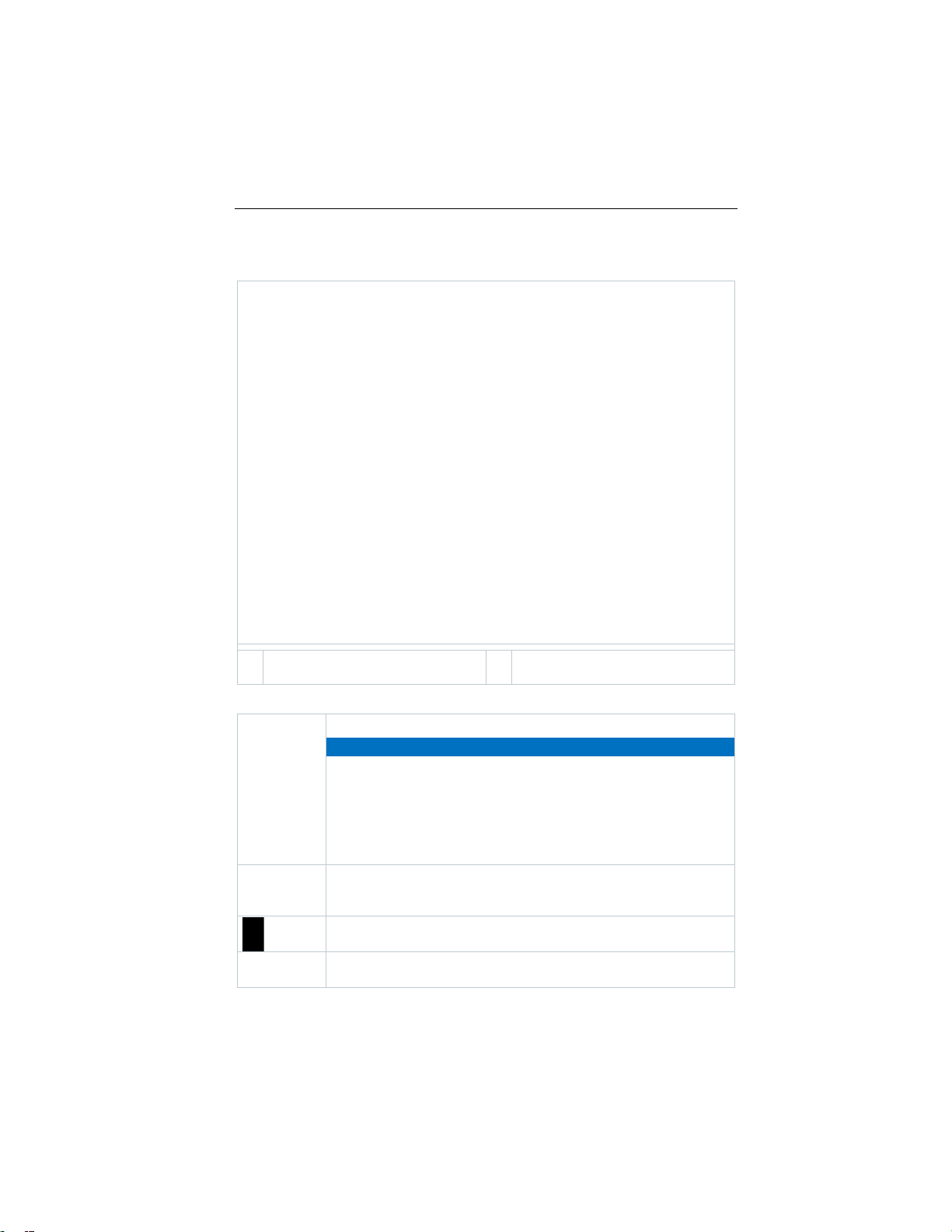
1
Attachment point for carrying
strap
2
Magnets
IMPORTANT
computers or credit cards).
At the end of its useful life, deliver the product to the separate
regulations) or return the product to Testo for disposal.
6 Product description
Rear view
Explanation of icons
Magnetic field
Damage to other devices!
- Keep a safe distance away from products that could be
damaged by the effects of magnetism (e.g. monitors,
collection point for electric and electronic devices (observe local
Next-Gen testo 300 complies with the Korean safety
standard.
Next-Gen testo 300 is Bluetooth-enabled
12
Find Quality Products Online at: [email protected]
www.GlobalTestSupply.com
Page 12
China RoHS
6.3
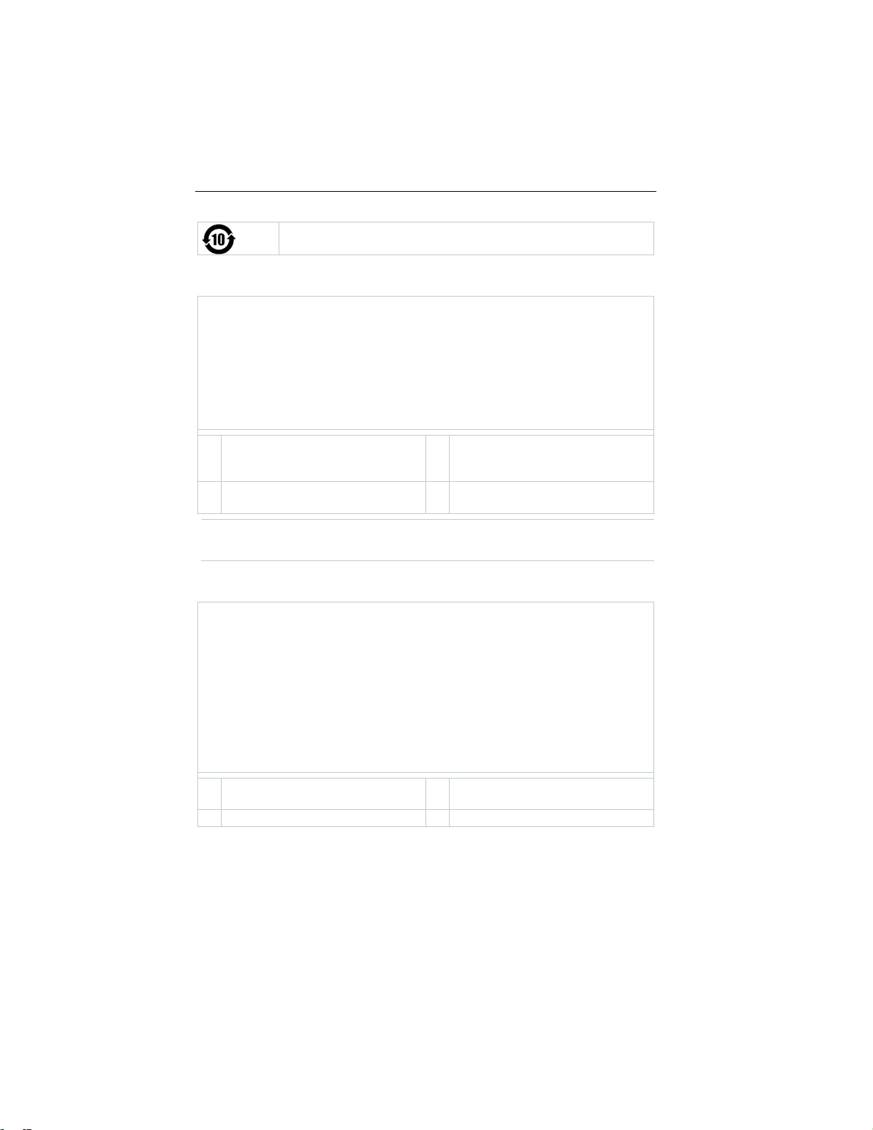
1
Probe connections for additional
Connector
3
Flue gas socket
2
Integrated ambient air probe
4
Differential pressure
measurement connection
6.4
1
window and particle filter
3
instrument
2
Probe handle
4
Connection cable
6 Product description
Connections
probes and testo Bluetooth®
There must be no more than one extension lead (0554 1201, 0554
1202) connected between flue gas socket and flue gas probe.
Compact flue gas probe
Removable filter chamber with
Find Quality Products Online at: [email protected]
www.GlobalTestSupply.com
Connector plug for measuring
13
Page 13

6.5
Removable filter chamber with
window and particle filter
Connector plug for measuring
instrument
2
Lock release
5
Probe handle
window and particle filter
instrument
2
Lock release
5
Probe handle
6 Product description
Modular flue gas probe
1
3 Probe module 6 Connection cable
Removable filter chamber with
1
3 Probe module 6 Connection cable
4
Connector plug for measuring
4
14
Find Quality Products Online at: [email protected]
www.GlobalTestSupply.com
Page 14

7 First steps
If the measuring instrument is completely discharged, allow at least 30
using it again.
1
2
7 First steps
7.1 Commissioning
Take the information in the testo information document (included with the
product) into account for this.
7.2 Power Supply / Battery
The measuring instrument is supplied with an energy storage unit.
Fully charge the battery before using the measuring instrument.
minutes to charge before switching the measuring instrument on and
If the power supply is connected, the measuring
instrument is automatically powered via the power supply.
Only charge the battery at an ambient temperature of
32 to 95 °F (0 to 35 °C).
Storage conditions for the battery:
• Ambient temperature from 50 to 68 °F (10 to 20 °C)
• Charge level of 50 to 80%
7.2.1 Charging battery
Connect the instrument plug of the charging cable to the USB socket
on the measuring instrument.
Connect the charging cable of the power supply to a power socket.
The charging process starts. LED in
the condensate trap flashes red.
The charging process stops
automatically when the energy
storage unit is fully charged. LED in
the condensate trap has a continuous
red light.
If the battery has discharged completely, the charging time at room
temperature is approx. 5-6 hrs.
15
Find Quality Products Online at: [email protected]
www.GlobalTestSupply.com
Page 15
7 First steps
1
2
Tapping
Swiping
7.2.2 Power Supply Operation
Connect the instrument plug of the Power Supply to the mini USB on
the measuring instrument.
Connect the power supply into a power supply.
The measuring instrument is powered via the power supply.
If the instrument is switched off and a battery is inserted, the charging
process will start automatically. Switching the measuring instrument
on stops the charging of the battery and the measuring instrument is
powered via the power supply.
For longer measurements involving mains operation, Testo
recommends using a combustion air temperature probe with
connection cable. Self-heating of the instrument during power supply
operation may influence the combustion air temperature measurement
using a mini ambient air probe.
7.3 Touchscreen Operation
Familiarize yourself with the touchscreen operating concept before you use the
measuring instrument.
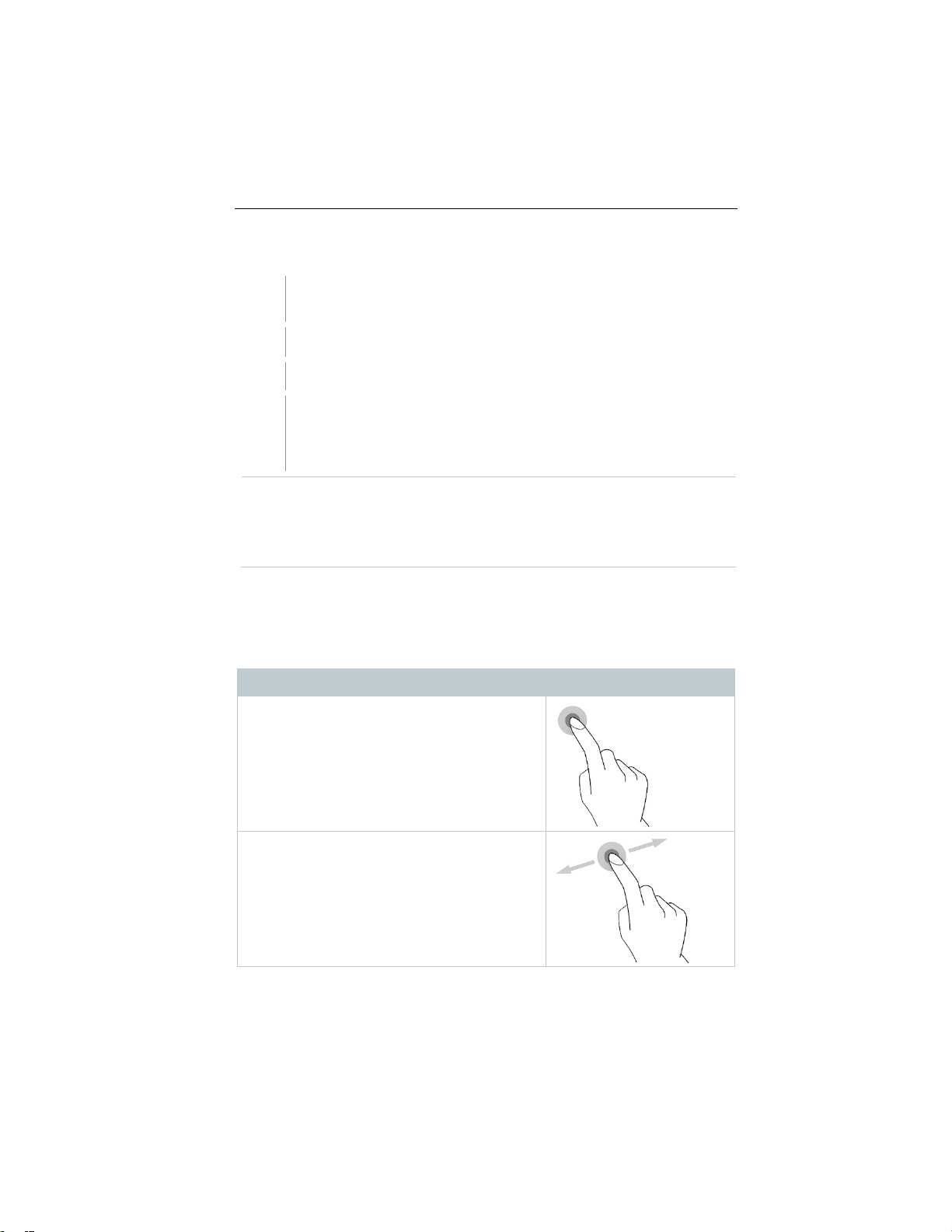
Actions are mostly carried out by:
Description
To open applications, select menu symbols,
press buttons on the display or enter characters
with the keypad, in each case tap these with a
finger.
Swipe to the right or left on the display to show
further views, e.g. to switch from the list view to
the graphic view.
16
Find Quality Products Online at: [email protected]
www.GlobalTestSupply.com
Page 16

7 First steps
Zooming
Dragging
7.4
Input field is enabled (flashing cursor)
1
Enter value: tap the required value
2
Confirm entry: Press .
3
Repeat steps as required.
Description
In order to make a section of the display larger
or smaller, touch the display with two fingers
and move them apart or together.
You can move an element by touching it,
holding it and dragging it to the required
position.
Example: Changing the display sequence of the
measurement parameters.
Keypad
Some functions require values (figures, numerical value, unit, characters) to be
entered. The values are entered via a keypad.
on the display (figures, numerical
value, unit, characters).
17
Find Quality Products Online at: [email protected]
www.GlobalTestSupply.com
Page 17

7 First steps
7.5
Instrument
Instrument is switched on.
The tutorial demonstrates the general operation and the most important
Instrument
Instrument is switched to standby mode.
button is pressed again.
Instrument
Selection: [OK] Instrument is switched
switched off with [Cancel].
Unsaved readings are lost when the measuring instrument is switched
Switching the inst rument on and off
Current
status
off
on
off
Action Function
Press the side
button for 3 seconds
When the measuring instrument is started for the first time, the setup
wizard guides you through the following setting parameters step by
step:
- Country version
- Language
- Wi-Fi
- Date and Time
- Own company address
- E-mail account
A tutorial can be started after the setup wizard.
functions of the measuring instrument using examples.
Press the side
button briefly
(< 1 s)
Press the side
button for a long
time (>1 s)
Standby mode has 3 time-dependent functions:
• Standby time up to 1 min: Immediate restart after pressing the key.
• Standby time up to 1 hour: After pressing the key, a restart takes
place after 5 seconds.
• Standby time more than 1 hour: Next-Gen testo 300 is in power
save mode. After pressing the key, a restart takes place after the
zeroing phase.
The instrument is re-activated when the
off or cancel the instrument being
off.
18
Find Quality Products Online at: [email protected]
www.GlobalTestSupply.com
Page 18

7.6
Instrument is switched on.
1
Insert the connector plug into the flue
Instrument is switched on.
1
Insert the connector plug of the
Connect probes
Flue gas probes
gas socket and lock it in place by
turning it slightly clockwise (bayonet
lock).
There must be no more than one extension line (0554 1202) between
measuring instrument and flue
Temperature adapter
7 First steps
gas probe.
probe into the probe socket.
System recognizes the probe (info is displayed).
The parameter which is measured with an external probe is identified
on the display by "ext.".
19
Find Quality Products Online at: [email protected]
www.GlobalTestSupply.com
Page 19
7 First steps
7.7
7.7.1
Danger of suffocation!
The testo Bluetooth
Keep out of reach of children.
1
Connecting Smart Probes and testo
Smart App
The Next-Gen testo 300 has the option of establishing a Bluetooth® connection
with wireless probes via the testo Bluetooth® Connector as well as a
connection to the testo Smart App at the same time.
If the Next-Gen testo 300 is used with Smart Probes, they must be at
least 8 inches (20 cm) apart.
Attaching the testo Bluetooth® Connector
(0554 3004)
Once the testo Bluetooth® Connector is plugged in, all the warning
and safety instructions for the Next-Gen testo 300 apply.
WARNING
®
Connector is a small part that can be swallowed.
Connect the testo B
Connector to the
socket on the Next-Gen testo 300.
When connected, a testo Bluetooth® Connector icon appears in
the Next-Gen testo 300 status display.
You can now connect up to 4 Smart Probes to the Next-Gen testo
300 at the same time.
luetooth®
TUC 1 or TUC 2
20
Find Quality Products Online at: [email protected]
www.GlobalTestSupply.com
Page 20

7 First steps
2
Press the ON button on the Smart
Probe.
The LED flashes yellow while connecting via Bluetooth® and then
flashes green when the connection is established.
Once the Smart Probe is connected
with the Next-Gen testo 300, this
reading appears on the display. The
product name and the product ID
(last three digits of the serial number)
indicate at a glance which Smart
Probe is providing the reading. The
readings are transmitted to the testo
300 NEXT LEVEL in fixed measuring
cycles of 1 second.
If the Next-Gen testo 300 receives no new measuring value at the
expected receiving time, e.g.:
- the Smart Probe is outside the connection range
- another problem causes an interrupted connection
no more readings are shown on the Next-Gen testo 300 (display: "----")
Carrying out the normal testo 300 FW update is sufficient to update the
testo Bluetooth® Connector. The testo Bluetooth® Connector then
receives the update when the Next-Gen testo 300 is next switched off.
This means that every testo Bluetooth® Connector with an older
version is updated during switch-off. This is indicated by the
continuous red flashing condensate trap.
21
Find Quality Products Online at: [email protected]
www.GlobalTestSupply.com
Page 21
7 First steps
7.7.2
testo 115i - clamp thermometer with smartphone
operation
0560 1510
testo 510i - differential pressure measuring instrument
with smartphone operation
smartphone with
You can get the App for iOS instruments in the App Store or for Android
Smart Probes compatible with the
instrument
Order number Designation
0560 2115 03
0563 4915
testo 915i - Wireless thermometer w flexible temp.
probe (TC type K) and smartphone operation
7.7.3 Establishing a connection with the testo
Smart App
In order to establish a connection, you need a tablet or
the testo App already installed on it.
instruments in the Play Store.
Compatibility:
• Requires iOS 13.0 or later/Android 8.0 or later.
• Requires Bluetooth® 4.0.
• Requires in testo 300 software version V12.7 or newer & firmware
version V1.10 or newer.
22
Find Quality Products Online at: [email protected]
www.GlobalTestSupply.com
Page 22

7.7.3.1
1
2
3
Instrument status bar
4
Configuration
5
6
7
Create measurement report
8
9
App user interface
Element Element
Main menu
Readings from Next-Gen testo
300
7 First steps
Current Next-Gen testo 300
instrument status
Remote save of measurement
on Next-Gen testo 300
Fuel selected in Next-Gen testo
300
Remote measurement start/
stop on Next-Gen testo 300
7.7.3.2 Measurement menu – testo 300 Second Screeen
The testo Smart App features several stored measurement programs.
Depending on the measurement task, these enable the user to configure and
carry out the measurement conveniently. To use the Next-Gen testo 300 with
the testo Smart App, only the measurement program testo 300 Second Screen
is used.
Basic view
In the Basic View application menu, the current measured values can be read,
recorded and saved. The basic view is particularly suitable for quick and
simple measurements. All Bluetooth® probes (apart from Next-Gen testo 300)
compatible with the testo Smart App are displayed in the basic view.
23
Find Quality Products Online at: [email protected]
www.GlobalTestSupply.com
Page 23

7 First steps
1
2
Click on the testo 300 Second Screen.
3
Follow the instructions and enter the pin in the field provided.
4
Click on Apply Configuration.
300
creen
Second
Screen measurement program, all measurement
testo 300 Second S
With
data of the Next-Gen testo 300 can be transferred to the smartphone or
tablet and the measurement can be controlled from both devices.
the
testo
7.7.4 Connecting for the first time
Click on Measure.
The following window opens.
For detailed information on how to obtain the pin, see section 8.2.4
Second Screen.
24
Find Quality Products Online at: [email protected]
The PIN only needs to be entered when connecting for the first time.
After that,
recognized by the testo Smart App and the connection is established.
The connection is automatically established.
the configured Next-Gen testo 300 is automatically
www.GlobalTestSupply.com
Page 24
7.7.5
Carrying out the measurement
1 2 3
4
Click on required activity:
7.7.6
1
2
Click on Language.
Open the testo Smart App.
7 First steps
Click on Measure
Click on the testo 300 Second Screen measurement program.
The connection to the Next-Gen testo 300 is automatically
established (this may take a few seconds).
Once the connection has been established between the App and NextGen testo 300, the App will be in Second Screen m
represented by
measurement data from the Next-Gen testo 300 is mirrored on the App.
The measurement can now be controlled from both instruments.
• Start measurement: click on Start.
• Stop measurement: click on Stop.
• Request the measurement report from Next-Gen testo 300: click on
Request PDF from testo 300.
• Save measurement on the Next-Gen testo 300: Click on Save.
No other measuring apps from the Smart App can be used while the
connection is being established.
To establish a connection, the Smart App connection must be
activated on the Next-Gen testo 300.
To establish a connection, the Wi-Fi must be activated on the
smartphone/tablet.
.
a yellow f
in the App. This means that all
rame
ode. This
Settings – language
Click on Settings.
The Settings menu opens.
A window with different languages opens.
25
Find Quality Products Online at: [email protected]
www.GlobalTestSupply.com
Page 25
7 First steps
3
Click on the required language.
7.7.7
7.7.7.1
1
2
Click on Instrument information.
>
Use the slider to activate or deactivate Update for connected
7.7.7.2
1
2
Click on Tutorial.
7.7.7.3
1
2
Click on Exclusion of liability.
The required language is set.
Help and Information
Under Help and Information, you will find information about the testo Smart App.
The stored tutorial can be called up and implemented. This also where legal
information can be found.
Instrument information
Click on Help and Information.
The Help and Information menu opens.
The current App version, Google Analytics instance ID, refrigerant
version and update are displayed for the connected instrument.
Automatic updates for instruments can be enabled or disabled.
instruments.
Tutorial
Click on Help and Information.
The Help and Information menu opens.
The tutorial shows you the most important steps prior to
commissioning.
Exclusion of liability
Click on Help and Information.
The Help and Information menu opens.
26
Find Quality Products Online at: [email protected]
www.GlobalTestSupply.com
Page 26
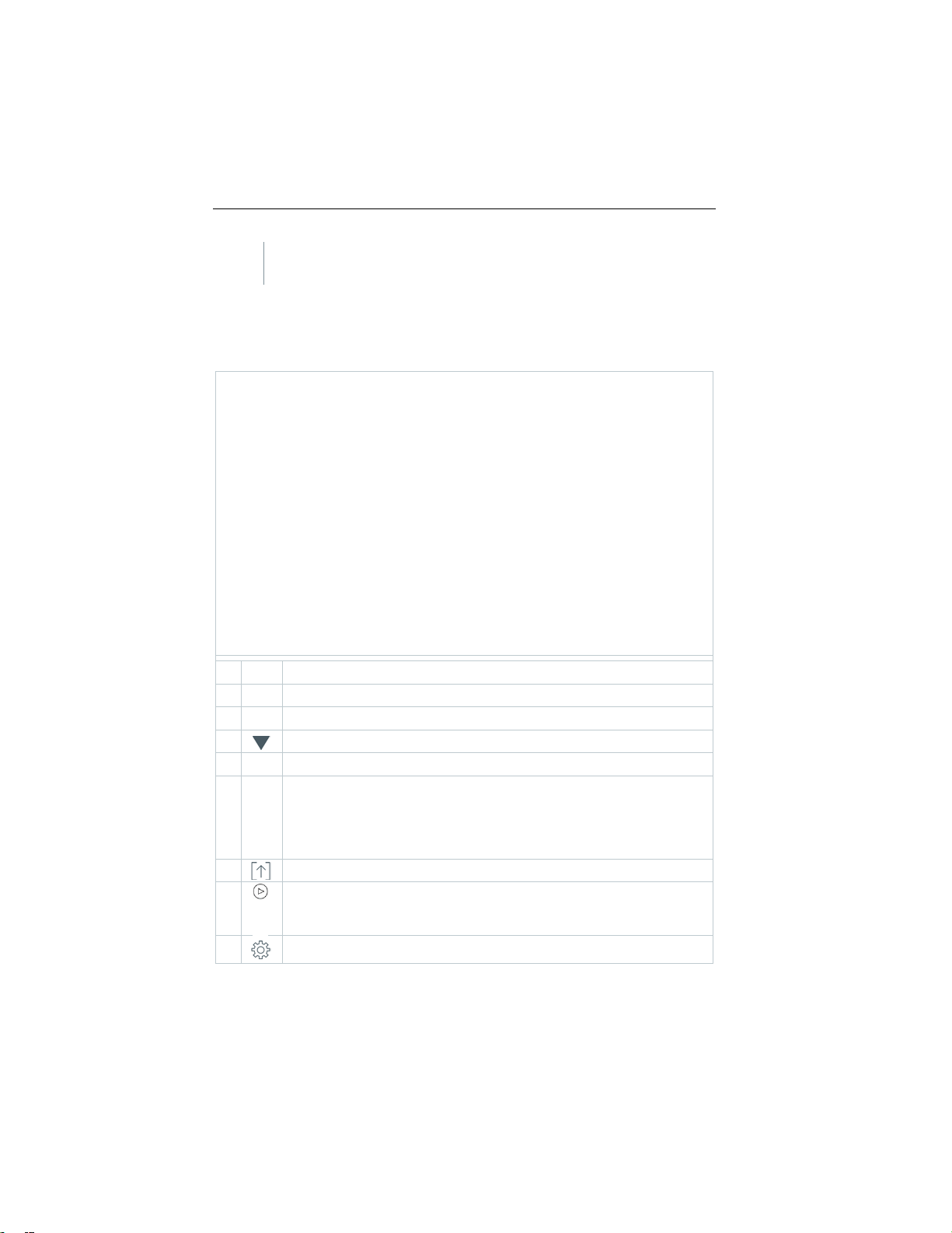
8
8.1
1
Measuring applications
2
3
Main menu
4
Open Fuels selection list
5
Customer/Measuring sit e
Select reading display type:
7
Start measurement
Stop measurement
The data protection information and licence usage information is
displayed.
Usi ng the product
User interface
8 Using the product
Status bar
Select
• List
6
8
9
• Chart
• Hot Spot
Edit measurement data
Pause measurement
Options
27
Find Quality Products Online at: [email protected]
www.GlobalTestSupply.com
Page 27
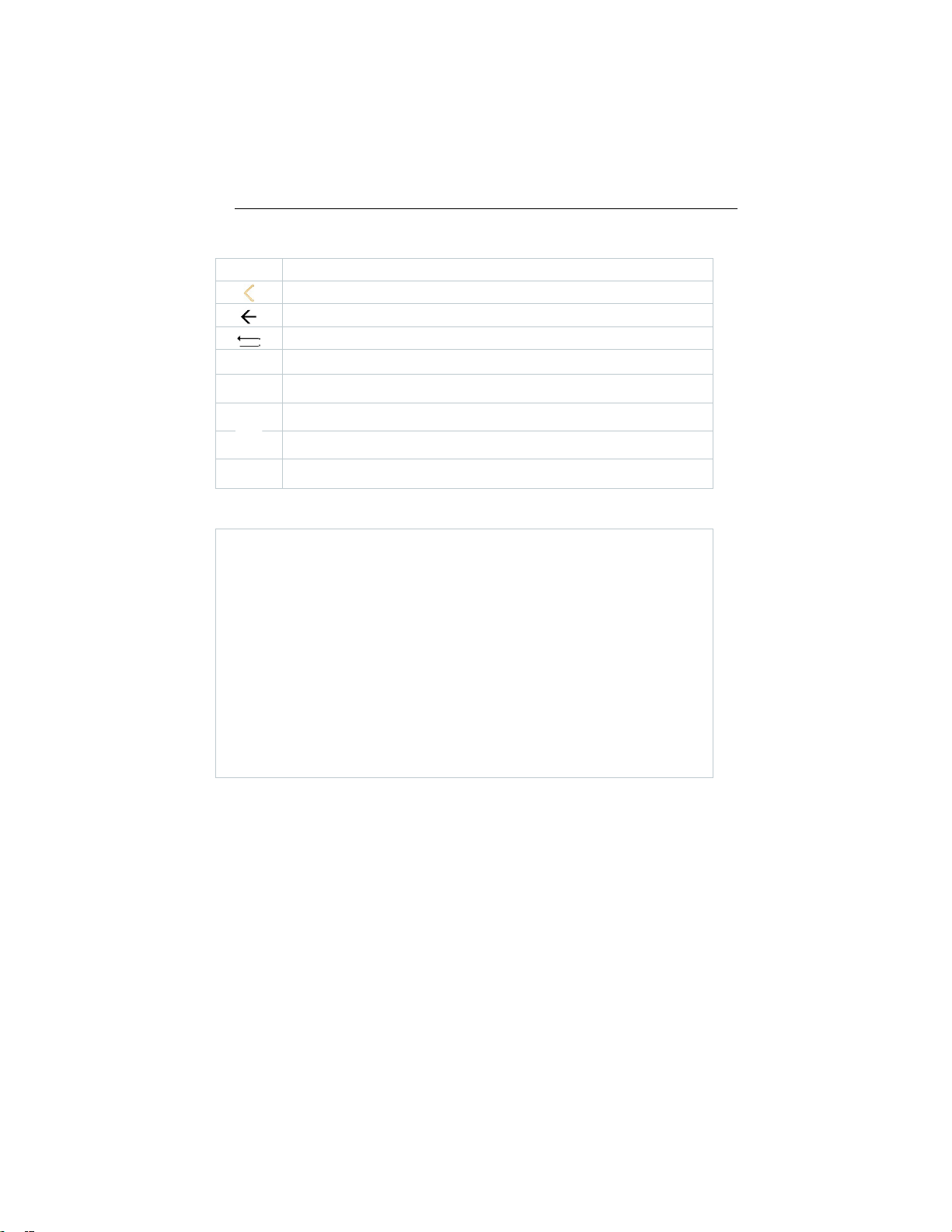
8 Using the product
Further symbols on the user interface (without numbering)
Retry measurement
One level back
One level back
One level back
Cancel process
Print values
Save report
Save and send report
Generate QR code
8.1.1 List reading display type
The measurement parameters/units and the number and order of the
measurement parameters displayed in the List reading display type can be set,
see Section Edit View.
Only those measurement parameters and units that are enabled in the reading
display appear in the reading display, in the saved measurement protocols and
on the report printouts.
The settings only apply to the measurement type currently enabled.
28
Find Quality Products Online at: [email protected]
www.GlobalTestSupply.com
Page 28

8 Using the product
8.1.2 Graphics reading display type
In the Graphics reading display type, the reading progression can be displayed
as a line diagram.
A maximum of 4 measurement parameters can be set at any one time. Only
those measurement parameters/units can be displayed that are available in the
List reading display type.
The measurement parameters/units can be adjusted if necessary:
Measurement view is enabled.
1
Call up function: Graphics
2
Tap on in order to open selection list for measurement
parameters/units.
3
Select desired measurement data / units.
Selection is accepted automatically.
29
Find Quality Products Online at: [email protected]
www.GlobalTestSupply.com
Page 29

8 Using the product
8.1.3 Hot Spot reading display type
Search for corestream:
Measurement view is enabled.
1
Call up function: Hot Spot
2
Start search:
Perform zeroing.
3
The measurement starts automatically after zeroing.
4 Align the flue gas probe in the flue gas
duct so that the probe tip is in the
corestream (area of the highest flue
gas temperature Max FT).
- Grey value/grey pointer: Display
of current flue gas temperature
- Orange value/orange pointer:
Display of maximum flue gas
temperature
- Reset values/pointer:
30
Find Quality Products Online at: [email protected]
www.GlobalTestSupply.com
Page 30
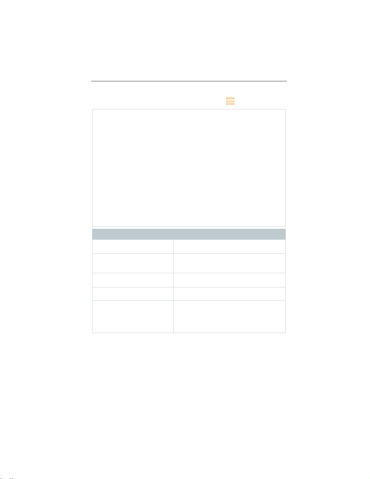
8.2
Customer/Measuring site
Create, edit and delete customer and system
information.
Call up, delete and send measurements that
possible).
Saved reports
Call up and delete measurement report.
Second Screen
Connection to the testo Smart App can be
activated or deactivated.
Gas path check
For flawless operation of the measuring
recommended.
8 Using the product
Overview of main menu ( )
Main menu Description
Tests
32
have been performed (various formats
instrument, regular tightness testing of
measurement systems (measuring
instrument + flue gas probe) is
Find Quality Products Online at: [email protected]
www.GlobalTestSupply.com
Page 31

Main menu Description
Device Settings
Settings
Sensor Diagnosis
Overview of the sensors fitted and their
condition.
Error List
Call up error reports
Device information
Information
- qA date
Server information
Information about the available server
E-Mail
Set up e-mail account and the e-mail
- Country version and language
- Wi-Fi
- Date & Time
- Own company address
- Hotspot
- Rechargeable battery management
- Display brightness
- Manage e-mail accounts
- CO/NO sensor protection
- NO2 addition
- O2 reference
- Alarm limits
- Device name
- Serial number
- Instrument identification number
- Last service
- Free memory
- Operating hours
- Operating hours since last service
- Software version
- Firmware version
- Firmware date
- qA version
8 Using the product
account can be called up.
To set up the e-mail account on the
Next-Gen testo 300 the IMAP setting in
your e-mail account with your provider
must be activated. You can find more
information in your e-mail account itself,
e.g. under FAQs or Settings.
Find Quality Products Online at: [email protected]
www.GlobalTestSupply.com
33
Page 32
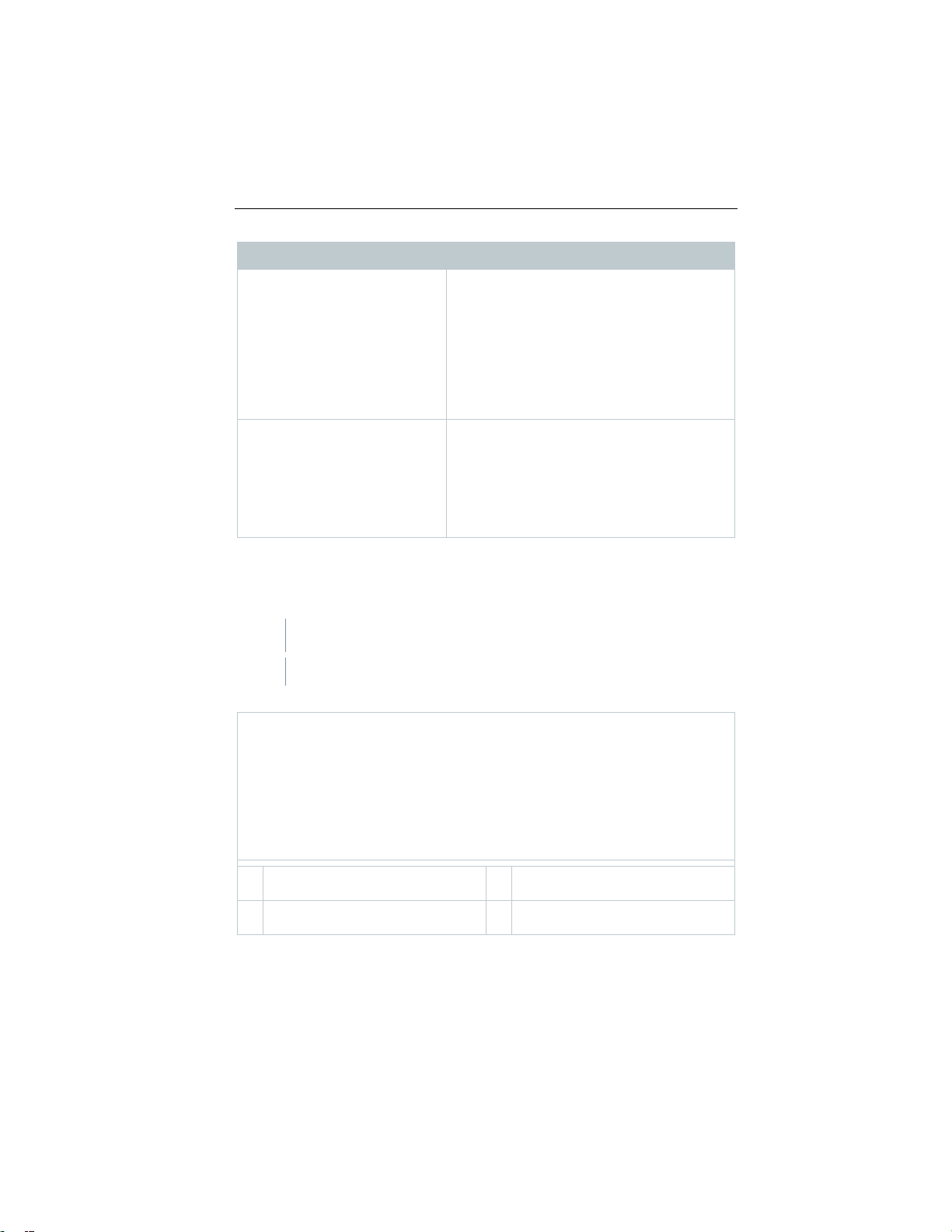
8 Using the product
My Apps
Additional applications
- File manager
Help
Aids
8.2.1
1
View/edit existing data about
Customer / Measuring site
Create new Customer / Measuring
site
Main menu Description
- Alarm clock
- E-mail
- Gallery
- Browser
- Calendar
- Pocket calculator
- QuickSupport
- Device Support
- Tutorial
- Setup Wizard
- Help Online
- Testo website
- Update via USB
Customer / Measuring site
Create, edit and copy Customer / Measuring site information.
Customer / Measuring site can be deleted.
Call up function: | Customer / Measuring site
Customer / Measuring site menu is displayed.
The following functions are available:
1 Search 3
2
34
Find Quality Products Online at: [email protected]
www.GlobalTestSupply.com
Page 33

Search
1
Tap Search operating field.
2
Enter search test using the text editor.
Via the search text, only the Customer / Measuring site is
3
1
Tap + New Customer / Measuring site.
2
Tap the required input field.
3
Enter the information via the keypad.
4
5
Save.
In order to be able to select a customer, at least one measuring site
A customer is created.
1
Tap Measuring site button.
2
Tap + New measuring site operating field.
Text cursor flashes.
displayed that contains characteristics of the search text.
Confirm search result: press .
Create new customer
Customer input screen is opened.
Keypad appears.
8 Using the product
Confirm each input with .
The Customer/Company Name input field is a required field and must
be filled in.
Customer is created.
must be created and selected!
Create new measuring site
35
Find Quality Products Online at: [email protected]
www.GlobalTestSupply.com
Page 34

8 Using the product
3
Enter data.
input field is a required field and must be
4
5
Save.
1
Tap customer.
2
Input fields can be edited.
Customer input screen is open.
1
Tap Measuring site button.
2
Select Measuring site.
3
Edit data.
4
Save.
1
2
3
Measuring site parameters menu is opened.
The Name of measuring site
filled in.
Confirm each input with .
An additional button (>) appears in some input fields.
These buttons contain a selection of parameters which are adopted in
the input field by tapping on them.
Edit customer
Customer input screen is opened.
Edit measuring site
8.2.2 Tests
Call up function: | Tests
Tests menu is displayed.
Select customer.
Open measuring site.
36
Find Quality Products Online at: [email protected]
www.GlobalTestSupply.com
Page 35
8 Using the product
4
Measurements for the selected
Format and print
Sweeps in Germany).
Comments and pictures
customer/measuring site can be
viewed and deleted .
More options for selected
measurement :
Print readings
Save report
Save and send report
Generate QR code
The following information can be selected/added to create a report.
Category Description
Select output format(s):
- CSV (comma separated text file, e.g. for
Microsoft
- PDF
- QR
- QR_ZIV
- ZIV 2.00 (XML file, complying with the
regulations of the Guild of Master Chimney
Customer data
Enter/add contact details.
Enter comments and Add (opens the Gallery).
Pictures are only included when output is in PDF
format.
®
Excel)
37
Find Quality Products Online at: [email protected]
www.GlobalTestSupply.com
Page 36
8 Using the product
Select measurements
Signature
5
Back to the measurement menu: tap .
8.2.3
1
1
Tap required report.
1
Touch required report for >2 sec.
Category Description
All saved measurements are displayed in one of
the following time categories, depending on the
creation date: Today, Yesterday or Older.
The measurements selected to create the report
are identified with .
Sign report.
Back to the main menu: tap
or
If you have saved more than 100 measurements, they can be stored in
the archive folder. A dialogue window appears automatically and you
can choose whether you want to create this archive folder or not.
Saved reports
The measurement reports that have been created are stored under Saved
reports. These can be called up again, sent or deleted.
Call up function: | Saved reports.
The OI File Manager folder is opened and the available reports are
displayed.
Open report
Report is displayed as a PDF.
Delete report(s)
38
Find Quality Products Online at: [email protected]
www.GlobalTestSupply.com
Page 37
Report is marked.
2
If necessary, mark more reports by tapping.
3
1
Touch report for >2 sec.
2
If necessary, mark more reports by tapping
3
4
Tap Send.
5
Send report by e-mail.
1
2
Tap Settings.
3
Disable in ascending order under sort settings.
Delete report(s): tap .
Send report(s)
Report is marked.
8 Using the product
Tap symbol.
Sort report(s)
Tap symbol.
The latest reports are displayed first.
39
Find Quality Products Online at: [email protected]
www.GlobalTestSupply.com
Page 38

8 Using the product
1
2
3
When connecting to the testo Smart App for the first time: enter the
4
Back to Main menu: tap .
8.2.5
1
2
Place the black sealing cap on the tip of the flue gas probe.
The pump flow is displayed. If the flow rate is less than 0.02 l/min, the
gas paths are not leaking and the measurement is ended.
3
Remove the sealing cap from the probe tip.
4
8.2.6
8.2.6.1
8.2.4 Second Screen
In the Second Screen menu item, the Smart App connection can be activated or
deactivated. This is also where the connection PIN required for the initial
connection is stored.
To connect the Next-Gen testo 300 to your smartphone or tablet, the Second
Screen connection must be activated.
Call up function: | Second Screen
Tap the Smart App connection selection field to activate (
)/deactivate ( ).
displayed connection PIN in the testo Smart App, under the testo 300
Second Screen measurement program.
Gas path check
For flawless operation of the measuring instrument, regular tightness testing of
measurement systems (measuring instrument + flue gas probe) is
recommended.
Call up function: | Gas path check
Gas path check starts automatically.
Back to the main menu: tap .
Device settin g s
Country version and language
Set up your measuring instrument country-specifically.
The country version configuration affects the measurement parameters, fuels,
fuel parameters and the bases of and formulas for calculations that are enabled.
40
Find Quality Products Online at: [email protected]
www.GlobalTestSupply.com
Page 39

8 Using the product
1
1
Tap Country version selection field.
2
Select country version.
3
Tap Next.
Country & language settings menu
1
Tap Language selection field.
The country version configuration affects the user interface languages that can
be enabled.
Call up function: | Device Settings | Country versio n and
language
Set country version
The available country versions are displayed.
The query Change country version? is displayed.
The selected country version is configured (this may take a few
minutes). The Device Settings menu is then displayed.
Restart the measuring instrument to complete its configuration.
Set language
Configuration of the country version can be ended by
cancelling. The display goes back to Device Settings.
41
Find Quality Products Online at: [email protected]
www.GlobalTestSupply.com
Page 40
8 Using the product
2
The instrument is reconfigured to the selected language.
1
1
2
3
4
5
6
Add network
Enter network name using the keypad,
further options. Save entry.
Saved networks
Display of saved networks.
The available languages for the selected country version are
displayed.
Select Language and tap .
Back to the main menu: tap and .
8.2.6.2 Wi-Fi
A radio link, such as a Wi-Fi, is not relevant for carrying out
measurements.
Set up a connection to a Wi-Fi router or a Wi-Fi hotspot. The connection
enables the sending of measurement reports on site by e-mail.
Call up function: | Device Settings | Wi-Fi.
Tap Wi-Fiselection field.
Enable Wi-Fi: tap Off button or move grey point to the right.
Instrument switches to On. The point changes to green.
Display of all available Wi-Fi routers or Wi-Fi hotspots in the vicinity.
Select Wi-FiN router or Wi-Fi hotspot.
Tap Connect.
It may be necessary to enter the password for the selected Wi-Fi.
Connection is set up and shown by Connected.
Further entries via button
Category Description
set security standard and if necessary enter
42
Find Quality Products Online at: [email protected]
www.GlobalTestSupply.com
Page 41
Updating
Advanced
8.2.6.3
1
2
8 Using the product
Category Description
Updating the display of available networks.
Further Wi-Fi settings are displayed.
The Wi-Fi is disabled in standby mode and enabled again once you
quit standby mode. The enabling process may take a few seconds.
Date/Time
You can set the date, time and time zone in the Date/Time menu. You can
choose between the 24 hr or AM/PM formats for the time.
If the Wi-Fi has already been enabled, the Date/Time provided by the
network is automatically set.
Call up function: | Device
Settings | Date/Time.
Various setting options are displayed. Depending on your
requirements, you can
• Enable ( ) / disable( ) selection fields by tapping
• Open other selection fields
• Enter parameters using the keypad
• Set 24 hr or AM/PM format: 24 hr ( ) / AM/PM ( )
Back to the Device Settings menu: Tap | | .
43
Find Quality Products Online at: [email protected]
www.GlobalTestSupply.com
Page 42

8 Using the product
1
Tap Date/Time.
2
Tap Autom. Date/Time.
3
Select Off.
4
Tap Set Date.
5
Select date via the calendar and confirm with OK.
6
Tap Set Time.
7
Tap hour and set.
Set Date/Time manually
Autom. Date/Time is disabled. The pop-up window closes
automatically.
44
Find Quality Products Online at: [email protected]
www.GlobalTestSupply.com
Page 43

8 Using the product
8
Tap minute, set and confirm with OK.
9
1
Tap Time Zone.
2
Tap Autom. Time Zone and disable ( ).
3
Tap Select time zone.
1
Select desired time zone.
2
8.2.6.4
1
Call up function: | Device Settings | Own company address
2
Tap the required input field.
3
Enter the information via the keypad.
4
5
Back to the Device Settings menu: tap .
8.2.6.5
Back to the Device Settings menu: tap | | .
Set time zone manually
Back to the Device Settings menu: tap | | .
Own company address
Enter own company address. This information will be shown on the reports.
Contact information input screen is opened.
Keypad appears.
Confirm each input with ✓.
Hotspot
Enable a hotspot in order to be able to transmit readings to software / industry
software.
The interface must also be available in the software / industry software.
Call up function: | Device Settings | Hotspot
1
45
Find Quality Products Online at: [email protected]
www.GlobalTestSupply.com
Page 44

8 Using the product
2
3
Back to the Device Settings menu: tap .
1 2 3 4 5
6
.
8.2.6.6
1
management
2
Select between the standby options by tapping the selection field.
3
Back to the Device Settings menu: tap .
8.2.6.7
2
Adjust the display brightness using the slide control.
3
Back to the Device Settings menu: tap .
8.2.6.8
1
Call up function: | Device Settings | Manage e-mail accounts.
2
An e-mail account can be added by clicking on the plus icon.
3
Back to the Device Settings menu: tap .
By tapping the selection field, enable ( )/disable ( ) Hotspot.
Edit hotspot name and password
Tap Hotspot settings.
Select Wi-Fi Hotspot.
Tap Set up Wi-Fi Hotspot.
Edit network name and password.
Tap Save.
Back to the Device Settings menu: tap
R echargeable battery management
Call up function: | Device Settings | Rechargeable battery
46
Display brightness
Call up function: | Device Settings | Display brightness
1
Manage e-mail accounts
Find Quality Products Online at: [email protected]
www.GlobalTestSupply.com
Page 45

8.2.6.9
1
Call up function: | Device Settings | Sensor Protect
2
Enter the alarm limit value via the keypad.
3
1
Call up function: | Device Settings | NO2 addition
2
Enter the addition value using the keyboard.
3
Confirm the input with OK.
4
Back to the Device Settings menu: tap .
8.2.6.11
1
Call up function: | Device settings | O2 reference
2
Enter the value via the keypad.
3
8 Using the product
CO/NO sensor protect
Limit values can be set to protect the CO/NO sensors against overload. Sensor
protect is enabled if these are exceeded:
• Fresh air dilution if exceeded (only for instruments with the "Dilution" option)
• Shutdown if exceeded again
When dilution is enabled, the CO and CO undiluted values are
displayed in a blue font. A “*” is shown on the printout after the name of
both values to indicate dilution.
CO input screen: Set Sensor Setting is opened.
Confirm input with .
The limit values must be set to 0 ppm to disable sensor protect.
8.2.6.10 NO2 addition (testo 300 Professional / Industrial)
O2 reference
The O2 reference value of the current fuel can be set.
O2 reference current fuel input screen is opened.
Find Quality Products Online at: [email protected]
Confirm input with .
47
www.GlobalTestSupply.com
Page 46

4
Tap [OK].
8.2.6.12
1
Call up function: | Device Settings | Alarm limits
2
Tap directly on the value in the relevant input field.
3
Enter the value via the keypad.
4
Confirm each input with ✓.
5
Tap [OK].
8.2.7
1
Call up function: | Sensor Diagnosis
8.2.8
1
Call up function: | Erro r list
8.2.9
1
Call up function: | Device information
8.2.10
1
Call up function: | Server information
8 Using the product
Alarm limits
Alarm limits can be set for the CO Ambient measurement type. An audible
alarm signal is triggered when the alarm limit is reached.
Alarm limits input screen is opened.
Keypad appears.
Sensor diagnosis
Overview of the sensors fitted and their condition.
Error list
Call up error reports.
Device information
Call up device information.
Server information
Information about the available server.
48
Find Quality Products Online at: [email protected]
www.GlobalTestSupply.com
Page 47

8.2.11
1
Call up function: | E-Mail
2
Enter e-mail address.
3
Enter password.
4
Set account options, such as synchronization interval
5
Entry of account name (optional) and name which appears with the
sent e-mails.
If the system does not accept the e-mail address and password
Setting up an e-mail account
An e-mail account has to be set up in order to be able to send
reports as e-mails. A Wi-Fi connection must be available to set the
account up.
The inbox of the e-mail account is opened.
combination, but you are certain it is correct, check the following
possible solutions:
• Open e-mail client, e.g. gmail, on a PC and check e-mail reception.
Your provider may have sent you a security e-mail that you need to
acknowledge before the e-mail account can be accepted on the
Next-Gen testo 300.
• Enable IMAP account
To do this, call up your e-mail account on the PC. You will find the
setting for the common e-mail providers, e.g. gmx, under settings POP/IMAP. Account-specific information about the enabling of the
IMAP account is supplied by the relevant provider. Find out about
this from the relevant provider or on the Internet.
• Manual set-up of the e-mail account
1. Call up function: | E-Mail.
2. Enter e-mail address.
3. Select Manual set-up.
4. Select Private account type (IMAP) (recommended).
5. Enter password.
6. Enter/change server, port and security type.
This information is e-mail account specific and is supplied
by your e-mail account provider. Find out about this from
your account provider or on the Internet.
8 Using the product
49
Find Quality Products Online at: [email protected]
www.GlobalTestSupply.com
Page 48

8 Using the product
7.
[Next]
8.
Enter/change SMTP server, port and security type.
your account provider or on the Internet.
9.
[Next]
10.
Set account options, such as synchronization interval.
11.
[Next]
12.
Entry of account name (optional) and name which appears
with the sent e-mails.
13.
[Next]
1
Call up function: | E-Mail
2
3
Enter the e-mail address via the keypad.
4
Fill in subject and create text.
mail using the paper
5
8.2.12
1
Call up function: | My Apps
This information is e-mail account specific and is supplied
by your e-mail account provider. Find out about this from
The inbox of the e-mail account is opened.
Call up e-mail account
Inbox menu is opened.
Create e-mail: tap .
Compose menu and the keypad is opened.
If required, additional files can be attached to the eclip symbol.
Send e-mail: tap .
E-mail is sent.
My Apps
Additional applications
Available Apps are displayed.
Find Quality Products Online at: [email protected]
50
www.GlobalTestSupply.com
Page 49

8.2.13
8.2.13.1
1
Call up function: | Help | Device Registration
8.2.13.2
1
Call up function: | Help | Tutorial
8.2.13.3
1
Call up function: | Help | Setup Wizard
2
The following settings can be made:
8 Using the product
Symbol Name
Alarm clock
Gallery
Browser
Calendar
Calculator
Quick Support
Help
Device registration
Testo would like to offer you the best possible customer service. Register your
instrument so that, when you call, our employees in Customer Service have all
the information they need available at all times, so that they can quickly provide
you with further assistance.
You will find the information you need for registration on the sticker on the back
of the instrument.
Follow the instructions on the display.
Registration gives you the following advantages:
• 1 year's additional warranty for free
• Always being up to date with the latest from Testo
Tutorial
The tutorial provides you with an overview of and an introduction to the
operation and functions of the instrument.
Setup Wizard
51
Find Quality Products Online at: [email protected]
www.GlobalTestSupply.com
Page 50

8 Using the product
Country version and language
8.2.6.1
8.2.6.2
Date/time
8.2.6.3
Contact information
8.2.6.4 (own company data)
Registration
8.2.13.1 (instrument registration)
3
Next >
4
If necessary, tap Start tutorial or End setup.
8.2.13.4
1
Call up function: | Help | Update via USB
2
Confirm info with OK.
3
Insert the connecting cable (0449 0134) into the USB port on the
measuring instrument, then connect it to the PC.
4
Copy the new instrument software file (t300.zip) to the identified
Length of the copying process: approx. 10 – 15 minutes
5
Disconnect the connecting cable from the measuring instrument.
Once the instrument software has been updated (duration approx. 1.5
use again.
Function Section
Wi-Fi
Setup is complete.
Update vi a USB
Testo recommends updating the firmware only when the charge
capacity is full.
Firmware update is started.
Your PC identifies the measuring instrument as a removable medium.
removable medium.
hrs), the measuring instrument will automatically reboot and is ready for
52
Find Quality Products Online at: [email protected]
www.GlobalTestSupply.com
Page 51

9
9.1
1
Check the condensate container fill level and if necessary empty
2
Check the particle filter of the flue gas probe for contamination and
9.2
>
9 Performing the measurement
Performing the measurement
Prepare for measurement
container, see Section 10.5 Empty condensate trap.
replace it in good time. If necessary, see Section 10.10 Check/replace
particle filter.
Zeroing phases
Measuring the combustion air temperature (AT)
If no external combustion air temperature probe or testo 915i Smart Probe is
connected, the combustion air temperature is measured via the integrated
temperature probe.
Gas zeroing
The gas sensors are automatically zeroed after the instrument is switched on.
Next-Gen testo 300 without probe zeroing option in the flue gas:
The flue gas probe must be in fresh air during the zeroing phase (30
seconds)!
Next-Gen testo 300 with probe zeroing option in the flue gas:
The flue gas probe may already be in the flue gas duct during the
zeroing phase (30 seconds).
Start zeroing of the gas sensors manually: | Zeroing Gas Sensors
Draft/pressure zeroing
The pressure sensors are zeroed when a pressure measuring function is called
up.
Next-Gen testo 300 without probe zeroing option in the flue gas:
The flue gas probe must be in fresh air during the zeroing phase!
The instrument must not be pressurized during zeroing!
Next-Gen testo 300 with probe zeroing option in the flue gas:
The flue gas probe may already be in the flue gas duct during the
zeroing phase. The pressure socket of the instrument must be free
(depressurized, not closed).
53
Find Quality Products Online at: [email protected]
www.GlobalTestSupply.com
Page 52
9 Performing the measurement
9.3
Regularly check the measurement system (measuring instrument + flue
>
9.4
>
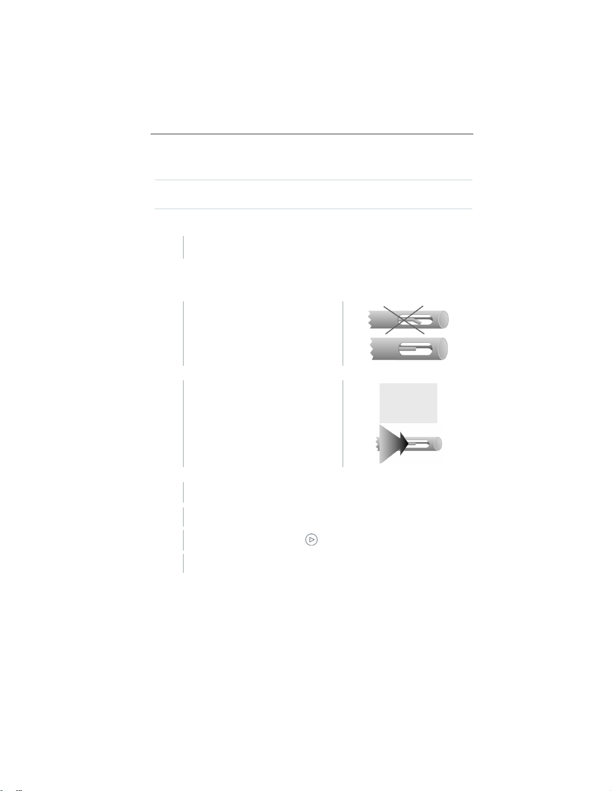
The thermocouple of the flue gas
>
The thermocouple must be freely
1 2 3
Carry out gas path check
gas probe) for leaks.
In particular, too high an O2 value may be an indicator of a leaking
measurement system.
| Gas path check.
Use of flue gas probe
Check thermocouple before use
probe must not be touching the probe
cage.
Bend the thermocouple back if
necessary.
Align flue gas probe
exposed to the flue gas flow.
Align the probe by turning it as
required.
Search for Hot Spot
The tip of the probe is in the hot spot of the flue gas.
Select Hot Spot.
Start corestream search: tap .
Perform zeroing. Please follow the instructions.
54
Find Quality Products Online at: [email protected]
www.GlobalTestSupply.com
Page 53

9 Performing the measurement
4
>
5
9.5
Measurement types
Align the flue gas probe in the flue
gas duct so that the probe tip is in
the hot spot (area of the highest
flue gas temperature Max FT).
Grey value/grey pointer: Display of current flue gas temperature
Orange value/orange pointer: Display of maximum flue gas temperature
Reset values/pointer: .
End Hot spot search: tap .
Overview of measurement types ( )
Flue Gas Analysis
Draft Measurement
CO Air Free
Smoke No.
Differential pressure
55
Find Quality Products Online at: [email protected]
www.GlobalTestSupply.com
Page 54
9 Performing the measurement
Measurement types
Differential temp.
Gas flow
Oil flow
CO ambient
1
O2 Air (EU Regulation)
Pipe Commissioning
Pressure Drop Test (EU Regulation)
Pretest (EU Regulation)
9.5.1 Flue Gas Analysis
In order to maintain the measuring accuracy of the instrument, the
correct fuel must be selected or configured.
Tap (Fuels)
> Select fuel.
To achieve usable measurement results, the test time of a flue gas
measurement should be at least 3 minutes and the measuring
instrument should display stable readings.
If a separate CO Air Free measurement has not yet been carried out,
this value is calculated using the readings from the flue gas probe and
continuously updated.
56
For this type of measurement, the Averaging option is also available.
See Averaging section.
Up to four Smart Probes can be used simultaneously during flue gas
measurement. This enables parallel measurement of the combustion air
temperature, the differential temperature and the differential pressure.
The following Smart Probes can be connected:
testo 915i (0563 4915), testo 510i (0560 1510), testo 115i
(0560 2115 03)
Call up function: | Flue Gas Analysis
Find Quality Products Online at: [email protected]
www.GlobalTestSupply.com
Page 55

9 Performing the measurement
2
3
4
Start measurement: tap .
Zeroing takes place.
Readings are displayed.
If the Draft measurement parameter is enabled in the reading
display, a draft measurement is automatically started in parallel to
the flue gas measurement. In the List measurement data view, the
parallel draft measurement can be stopped/restarted. This draft
measurement is performed separately to a measurement of the
Draft measurement type.
For the draught measurement, the minus connection for differential
pressure measurement must be free (ambient pressure, not closed).
Tap on the draught reading display or next to it.
End measurement: tap .
Automatic display after connection of one or more Smart Probe testo 115i
or testo 915i during flue gas measurement
If several temperature probes are connected in total (external probes and/or
testo 115i or testo 915i), the temperature probes are used for flue gas
measurement according to the following procedure.
The AT probe = external cable probe always has first priority.
57
Find Quality Products Online at: [email protected]
www.GlobalTestSupply.com
Page 56

9 Performing the measurement
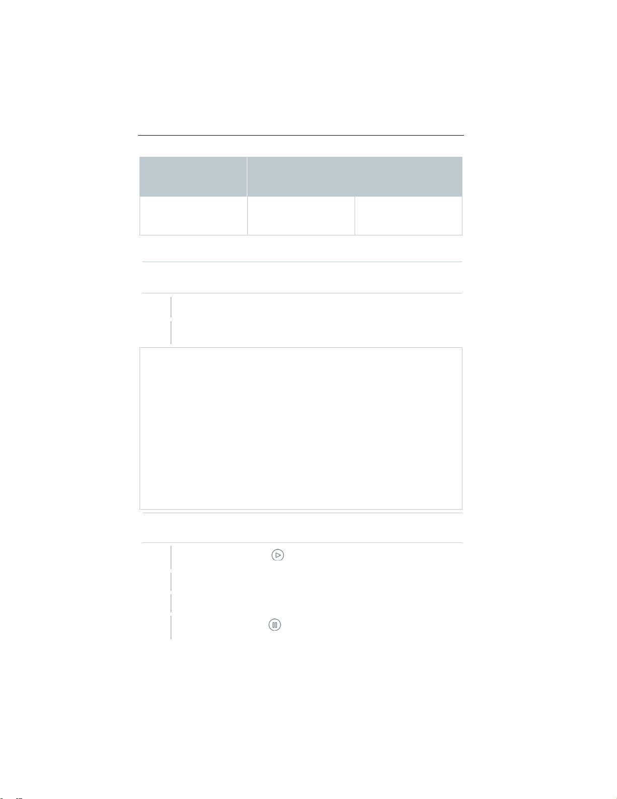
915i)
t115i: additional
measurement
Cable probes: AT probe for
the AT measurement
Cable probes: AT probe for
temperature channel T
Internal temperature sensor
temperature channel dT
Cable probes: AT probe for
temperature channel dT
A) min. one t915i connected
and temperature channel T
and temperature channel T
Internal temperature sensor
temperature channels dT
Connected cable probe
(maximum 1 possible)
No 1
Yes -
Yes 1
No 2
Yes 2
Number of connected Smart
Probes
(testo 115i and/or testo
Display and use of the
temperature probe in testo
300 NEXT LEVEL
temperature channel T
t915i: AT probe for the AT
the AT measurement
t115i/ t915i: additional
t300 NEXT LEVEL: AT
probe for the AT
measurement
t115i/t915i: additional
the AT measurement
t115i/t915i: additional
t915i: AT probe for the AT
measurement
t115i/t915i: additional
temperature channel dT
No 3
Yes 3
No 4
58
B) no t915i connected
Internal temperature sensor
t300 NEXT LEVEL: AT
probe for the AT
measurement
t115i: additional
temperature channel dT
Cable probes: AT probe for
the AT measurement
t115i/t915i: additional
temperature channel dT
t300 NEXT LEVEL: AT
probe for the AT
measurement
t115i/t915i: 2 additional
Find Quality Products Online at: [email protected]
www.GlobalTestSupply.com
Page 57
9 Performing the measurement
915i)
Cable probes: AT probe for
temperature channels dT
A flue gas probe must be connected.
1
2
3
Connected cable probe
(maximum 1 possible)
Yes 4
Number of connected Smart
Probes
(testo 115i and/or testo
9.5.2 Draft Measurement
For this type of measurement, the Mean value calculation option is
also available. See Mean value calculation section.
Call up function: | Draft Measurement
Display and use of the
temperature probe in testo
300 NEXT LEVEL
the AT measurement
t115i/t915i: 2 additional
The minus connection for differential pressure measurements must be
clear (ambient pressure, not closed).
Start measurement: tap .
Zeroing takes place. Please follow the instructions.
Reading is displayed.
End measurement: tap .
59
Find Quality Products Online at: [email protected]
www.GlobalTestSupply.com
Page 58

9 Performing the measurement
9.5.3 Solid fuel measurement
For performing solid fuel measurements complying with the 1st
BlmSchV, a Next-Gen testo 300 is required with the following
equipment:
• CO sensor H2-compensated for measurements (measuring range for
1st BImSchV
Testo 300 Industrial - 30,000 ppm)
• Measuring range extension by fresh air dilution
• Solid fuel adapter and probe shaft with pre-filter 0600 9765
1
Call up function: | Flue Gas
2
| | Options | Averaging | On
3
Zeroing is carried out.
The list for averaging opens.
The start button changes to .
4
Confirm with .
5
Enter measuring time (15 min). The required value can be entered in
the field.
measurement min. 20,000 ppm.
60
6
Confirm with .
7
Insert the flue gas probe into the exhaust pipe and position it in the hot
spot.
8
2
1
Start averaging with .
Stability time starts.
Press Continue to end the stability time manually.
After a maximum of 3 minutes, the stabilisation time ends and
the measurement starts automatically.
The system records the readings in the set measuring cycle.
During the measurement, the readings and the calculated
values are displayed.
Readings are automatically saved.
The measuring result is displayed after the measuring phase has
been completed.
End measurement early: .
Find Quality Products Online at: [email protected]
www.GlobalTestSupply.com
Page 59

9.5.4 CO Air Free
ulti-hole probe (0554 5762) must be connected.
A m
1
Call up function: |
2
Start
measurement: tap .
Reading is displayed.
3
End measurement: tap .
CO
Air
9 Performing the measurement
Free
61
Find Quality Products Online at: [email protected]
www.GlobalTestSupply.com
Page 60

9 Performing the measurement
The Smoke No. and Oil depos. parameters are only available for oil
1
2
Tap required value.
3
Enter value.
4
Confirm entry: tap ✓.
5
The differential pressure measurement can also be performed using the
The gas pressure kit (0554 1203) must be connected. Alternatively, the
9.5.5 Smoke number
fuels. The values calculated by a smoke tester can be entered.
Edit values
All values that can be modified have a dotted underlining.
Call up function: | Smoke No.
Keypad appears.
Reset readings: tap .
9.5.6 Differential pressure
For this type of measurement, the Averaging option is also available.
See Averaging section.
Smart Probe testo 510i (0560 1510).
Up to 4 testo 510i Smart Probes can be connected.
WARNING
Dangerous mixture of gases!
Danger of explosion!
- Make sure there are no leaks between the sampling point and the
measuring instrument.
- Do not smoke or use naked flames during the measurement.
Smart Probe testo 510i (0560 1510) can be used.
62
Find Quality Products Online at: [email protected]
www.GlobalTestSupply.com
Page 61

9 Performing the measurement
For an instrument with no dilution option: The minus connection for
1
2
Tap Differential pressure.
3
4
A differential temperature measurement can also be carried out with
Probes testo 915i (<1 second).
Two external temperature probes must be connected. Alternatively,
1
2
differential pressure measurement must be depressurized at the start of
the measurement (ambient pressure, instrument not connected to
system being checked), since the pressure sensor is zeroed.
Call up function: | Differential pressure
Start measurement. Tap .
Zeroing the pressure sensor.
Reading is displayed.
End measurement: tap .
9.5.7 Differential temperature
For this type of measurement, the Averaging option is also available.
See Averaging section.
The measurement can also be carried out using Smart Probes.
The following Smart Probes can be connected:
testo 915i (0563 4915), testo 115i (0560 2115 03)
just one Smart Probe testo 915i.
The measuring values (T1 and T2) for determining the differential
temperature can be recorded by pressing the button on the Smart
wireless Smart Probes such as the testo 115i or testo 915i can be
used. However, a maximum of just four Smart Probes can be used at
the same time.
Call up function: | Differential temp.
Start measurement: tap .
The measured values and the calculated differential temperature
Δt (T1 - T2) are displayed.
63
Find Quality Products Online at: [email protected]
www.GlobalTestSupply.com
Page 62

9 Performing the measurement
3
Connected cable probe
Number of connected Smart
testo 915i)
Display and use of the
Temperature channel T1:
dT is displayed.
Temperature channel T1:
"---".
Temperature channel T1:
dT is displayed.
dT is displayed.
Temperature channel T1:
displayed.
Temperature channel T1:
displayed.
End measurement: tap .
Automatic display after connection of several Smart Probe testo 115i or
testo 915i during differential temperature measurement
If several temperature probes are connected in total (external probes and/or
testo 115i or testo 915i), the temperature probes are used for differential
temperature measurement according to the following procedure.
(maximum 1 possible)
No 1
Yes -
Yes 1
No
Yes 2
Probes
(testo 115i and/or
2
temperature probe by
temperature channel
t115i/915i
Cable probe (ext2):
T2 and dT are displayed as
Cable probe (ext2):
Temperature channel T2:
t115i/915i:
Temperature channel T
t115i/915i
Temperature channel T2:
t115i/915i:
Cable probe (ext2):
Temperature channel T2:
t115i/915i:
dT is displayed.
Temperature channel T3:
t115i/915i:
T4 and dT are not
1:
t115i/915i
Temperature channel T2:
t115i/915i:
No 3
dT is displayed.
Temperature channel T3:
t115i/915i:
T4 and dT are not
64
Find Quality Products Online at: [email protected]
www.GlobalTestSupply.com
Page 63

9 Performing the measurement
testo 915i)
Temperature channel T1:
dT is displayed.
Temperature channel T1:
dT is displayed.
Temperature channel T1:
t115i/915i
An O2 dual wall clearance probe (0632 1260) must be connected.
1
2
Connected cable probe
(maximum 1 possible)
Yes 3
No 4
Yes 4
Number of connected Smart
Probes
(testo 115i and/or
Display and use of the
temperature probe by
temperature channel
Cable probe (ext2):
Temperature channel T2:
t115i/915i
dT is displayed.
Temperature channel T3:
t115i/915i
Temperature channel T4:
t115i/915i
t115i/915i
Temperature channel T2:
t115i/915i
dT is displayed.
Temperature channel T3:
t115i/915i
Temperature channel T4:
t115i/915i
Cable probe (ext2):
Temperature channel T2:
t115i/915i
dT is displayed.
Temperature channel T3:
t115i/915i
Temperature channel T4:
t115i/915i
dT is displayed.
Temperature channel T5:
9.5.8 O2 air (EU Regulation)
Call up function: | O2 supply air
Start measurement: tap .
Reading is displayed.
65
Find Quality Products Online at: [email protected]
www.GlobalTestSupply.com
Page 64

9 Performing the measurement
4
1
2
3
4
5
1
2
Set oil flow rate of the oil nozzle and oil pressure.
End measurement: tap .
9.5.9 Gas flow
The function is only available if the chosen fuel is a gas.
The gas burner capacity is calculated by means of the gas amount consumed. To
this end, a gas a
Call up function: | Gas Flow
Set the gas amount to watch for at the clock meter.
Set the calorific value of the burnt gas.
Start measurement: tap .
The test time is displayed.
When the set gas amount is reached: tap .
mount is input and its consumption read out at the clock meter.
The calculated gas flow and the gas burner capacity (in KW) are
displayed.
Edit values
All values that can be modified have a dotted underlining.
9.5.10 Oil flow calculation
The function is only available if the chosen fuel is an oil.
This function is used to calculate the capacity of the burner from the set oil
pressure and the oil flow rate of the oil nozzle.
Call up function: | Oil flow rate
The calculated oil burner capacity is displayed (in KW).
66
Find Quality Products Online at: [email protected]
www.GlobalTestSupply.com
Page 65

Edit values
• Cigarette smoke influences the measurement by more than 50 ppm.
An ambient CO probe (0632 1272) must be connected.
1
2
3
- Pipe volume < 100 l: Adjustment time 10 min, test time 10 min.
All values that can be modified have a dotted underlining.
9.5.11 CO ambient
The breath of a smoker influences the measurement by about 5
ppm.
• When using an ambient CO probe, note that:
The direction of flow of the gas has an effect on the accuracy of
measurement. Frontal flow onto the sensor leads to higher
readings. The best measurement results are achieved when the
probe is moved gently backwards and forwards.
• When using the ambient CO probe and the flue gas probe, note
that:
The probe must be in the fresh air (CO-free) during the zeroing
phase.
For this type of measurement, the Mean value calculation option is
also available. See Mean value calculation section.
9 Performing the measurement
Call up function: | CO Ambient
Start measurement: tap .
Reading is displayed.
End measurement: tap .
9.5.12 Pipe Commissioning (EU Regulation)
The pipe commissioning (using air or inert gas such as CO2 or N2) is a
tightness test for pipes, including fittings, but without gas appliances and the
relevant regulating and safety devices. The pipe commissioning is performed
after a load test has been successfully completed on newly laid gas pipes, or
after renovation of existing gas pipes, and is used for the acceptance of these
pipes. It shows up even the smallest leaks in gas pipes.
According to DVGW TRGI 2018 and ÖVGW G10, the stabilization time
and test time depend on the pipe volume.
67
Find Quality Products Online at: [email protected]
www.GlobalTestSupply.com
Page 66

9 Performing the measurement
- Pipe volume > 100 l to < 200 l: Adjustment time 30 min, test time
- Pipe volume > 200 l: Adjustment time 60 min, test time 30 min.
>
Connect the connector plug of the hose pressure connection kit
1
2
3
Pressurize the system.
4
5
The measuring value result can be assessed.
20 min.
(0554 1203) to the pressure test kit (0554 1213). Insert the pressure
adapter into the flue gas socket and lock by slightly turning it clockwise
(bayonet fitting).
Performing the measurement
The pressure socket of the instrument must be free (depressurized, not
closed).
Pressure zeroing has been carried out.
Call up function: | Pipe Comissioning
Set parameters or enter values.
All values that can be modified have a dotted underlining.
68
Once the pressure has built up, a stabilization time specified by DVGWTRGI 2018 should be observed to ensure that any possible pressure
fluctuations are not recorded in the measurement as well. The relevant
standard provides more detailed information.
Start stabilization time: tap . If applicable, follow instructions.
Reading is displayed.
Stabilization time is finished.
End stabilization time early: tap .
Measuring time starts.
The readings are automatically saved and displayed after the
measurement has been completed.
Find Quality Products Online at: [email protected]
www.GlobalTestSupply.com
Page 67

9 Performing the measurement
6
Conclude measurement: tap Next.
7
If applicable, repeat measurement: tap .
9.5.13 Pressure Drop Test (EU Regulation)
This measurement is performed to test the serviceability of an existing gas pipe
system (in contrast to the load test and pipe commissioning) and is used to check
the actual condition of the pipes. The pipe system may be in operation or disused.
Adhere to DVGW-TRGI 2018, worksheet G624!
Absolute pressure (parameter of the measuring location) must be
entered to obtain correct readings. If this is not known, it is advisable to
use the value 966 hPa (corresponds to 1013 hPa barometric, 400 m
above sea level).
> Insert the connector plug of the hose pressure connection kit (0554
1203) into the flue gas socket and lock it in place by turning it slightly
clockwise (bayonet fitting).
Performing the measurement
The pressure socket of the instrument must be free (depressurized, not
closed).
Pressure zeroing has been carried out.
Call up function: | Pressure Drop
1
Set parameters or enter values.
2
All values that can be modified have a dotted underlining.
Three circle diameters and three pipe lengths can be entered, which
are then used to calculate three partial volumes. The pipe volume is
calculated by adding these three partial volumes.
3 Pressurize the system.
test
69
Find Quality Products Online at: [email protected]
www.GlobalTestSupply.com
Page 68

9 Performing the measurement
4
5
6
The measuring value result can be assessed.
7
Conclude measurement: Tap Next.
8
>
Insert the connector plug of the hose connection kit (0554 1203) into
1
2
3
Start stabilization time. Tap . If applicable, follow instructions.
Reading is displayed.
Stabilization time is finished.
End stabilization time early: tap .
End measurement: tap .
Measuring time starts.
The readings are automatically saved and displayed after the
measurement has been completed.
If applicable, repeat measurement: tap .
9.5.14 Pretest (EU Regulation)
the flue gas socket and lock it in place by turning it slightly clockwise
(bayonet fitting).
Carrying out the measurement
The pressure socket of the instrument must be free (depressurized, not
closed).
Pressure zeroing has been carried out.
Call up function: | Pretest.
Set parameters or enter values.
All values that can be modified have a dotted underlining.
Start stabilization time: tap . If applicable, follow instructions.
70
Find Quality Products Online at: [email protected]
www.GlobalTestSupply.com
Page 69

9 Performing the measurement
4
The measuring value result can be assessed.
5
Conclude measurement: tap Next.
6
Reading is displayed.
Stabilization time is finished.
End stabilization time early: tap .
Measuring time starts.
The readings are automatically saved and displayed after the
measurement has been completed.
If applicable, repeat measurement: tap .
71
Find Quality Products Online at: [email protected]
www.GlobalTestSupply.com
Page 70
9 Performing the measurement
9.6 Overview of options ( )
Options Description
Edit measurem. view Add (add), delete ( ) measurement
parameters,
change display sequences ( ) and units (click
on (Unit).
Zeroing Gas Sensors Manually zeroing gas sensors.
Menu is only available for measurements
with gas sensors.
Zeroing Smart Probes Zero the differential pressure Smart Probe.
The menu is only available for
measurements with the Smart Probe testo
510i.
Averaging | On Calculation of a mean value within a preset
time.
72
Find Quality Products Online at: [email protected]
www.GlobalTestSupply.com
Page 71
9.6.1
1
Call up function: | Options | Edit View
2
Measurement parameter
- Accept changes: tap Confirm.
FT
Flue gas temperature
9 Performing the measurement
Edit view
Edit View menu is opened.
- Add: tap Add to open selection list of measurement parameters.
- Delete: tap on .
- Edit unit: tap on the measurement parameter you want to edit. Tap
on the required measurement unit in the selection list that has been
opened.
- Change position in the list: Press and hold and drag to the
required position.
Selection list (example: Country version Germany)
The overview of measurement parameters (available selection depends on the
chosen measurement type, fuel set and the sensors available in the measuring
instrument):
Display Measurement parameter
AT Combustion air temperature
Itemp Instrument temperature
Pump Pump performance
O2 Oxygen
73
Find Quality Products Online at: [email protected]
www.GlobalTestSupply.com
Page 72

9 Performing the measurement
ber Ø
Display Measurement parameter
CO2 Carbon dioxide
qAnet Flue gas loss without consideration of the calorific value range
Effn Efficiency without consideration of the heat value range
qAgr. Flue gas loss with consideration of the calorific value range
Effg Efficiency with consideration of the calorific value range
Draft Flue draft
ΔP Differential pressure
CO Carbon monoxide
uCO Undiluted carbon monoxide
NO Nitrogen monoxide
NOx Nitrogen oxides
λ Fuel-air ratio
AmbCO Ambient carbon monoxide
O2ref Oxygen reference
ΔT Differential temperature
Dew Pt Flue gas dewpoint temperature
Smoke 1
Smoke 2
Smoke 3
Smokenum
Only those measurement parameters and units that are enabled in the
reading display appear in the reading display, in the saved
measurement protocols and on the report printouts.
The settings only apply to the measurement type currently enabled.
74
Find Quality Products Online at: [email protected]
www.GlobalTestSupply.com
Page 73

9.6.2
>
9.6.3
1
Select required measurement type.
2
3
Determine the measuring rate (1 sec - 120 sec). The required value can
4
5
Determine the measuring time (30 sec - 90 min). The required value
6
7
9 Performing the measurement
Zeroing Gas Sensors
Zeroing of the gas sensors can be started manually.
| Zeroing Gas Sensors
The gas sensors are zeroed.
Next-Gen testo 300 without probe zeroing option in the flue gas:
The flue gas probe must be in fresh air during the zeroing phase (30
seconds)!
Next-Gen testo 300 with probe zeroing option in the flue gas:
The flue gas probe may already be in the flue gas duct during the
zeroing phase (30 seconds).
Mean value calculation
The mean value calculation option is only available in the country
versions x, y, z...
The mean value calculation option can only be set for the
following measurement types: Flue gas, Draft, Differential
pressure, Differential temperature and CO Ambient.
Call up function: | Options | Mean value calculation | On
The list for mean value calculation is opened.
The start button changes to .
be entered directly in the field on the first two lines of the display.
Confirm with .
can be entered in the field.
Confirm with .
Start mean value calculation with .
75
Find Quality Products Online at: [email protected]
www.GlobalTestSupply.com
Page 74

9 Performing the measurement
• Stabilization time begins. It can be terminated manually by selecting
8
9.7
Protocols
Feature
Print values
Print out measuring values via Bluetooth®.
Save
Save measuring values, including selected
values can be retrieved in the main menu.
Next.
• After a maximum of 3 minutes, the stabilization time ends and the
measurement starts automatically.
• The system records the readings in the set measuring cycle.
• During the measurement, the readings and the calculated values
are displayed.
• End measurement early: .
• Readings are automatically saved.
• The measurement result is displayed.
Carry out another measurement: .
Overview of protocols ( )
customers/measuring sites. Saved measuring
76
Find Quality Products Online at: [email protected]
www.GlobalTestSupply.com
Page 75
9 Performing the measurement
Protocols
Feature
Finish protocol
Create, save and send measurement report,
Saved reports can be retrieved in the main menu.
Share
Transfer to external software
- share TJF file
9.7.1
The printer is switched on and within wireless range.
1
2
Tap Print values.
9.7.2
including
- Own company data
- Format and print
- Customer data
- Comments and pictures
- Select measurements
- Signature
- via QR Code
The current readings are printed via a Bluetooth® printer (accessories: Testo
printer 0554 0621).
Carry out print text settings
Print text settings can be carried out and the reading printout can be
supplemented with individual creator information (header: company address;
footer: name of technician), see Section 8.2.5.4 Own company address.
Print current readings
Print data
tap .
Protocols menu is opened.
The protocol is created and sent to the printer.
The protocol is printed.
Bluetooth® is always activated on the Next-Gen testo 300.
Save
The measurement data from the last measurement carried out of each
measurement type is saved on the measuring instrument.
77
Find Quality Products Online at: [email protected]
www.GlobalTestSupply.com
Page 76

9 Performing the measurement
1
2
Tap Save.
9.7.3
1
2
Tap Finish protocol.
3
Enter/select log data:
Measurements that have been carried out can be saved to back up the
measurement data and for the subsequent creation of a report:
tap .
Protocols menu is opened.
The measurement protocol is saved.
Only saved readings can be further processed at a later stage for a
report.
The readings are automatically saved for the following measurement
types:
• Tightness test 1
• Tightness test 2
• Let by test
• 4 Pa measurement (DE country version)
• First German Federal Immission Control Ordinance (BImSchV) (DE
country version)
• Averaging (IT country version)
Finish protocol
tap .
Protocols menu is opened.
Options for Protocols are opened.
78
Find Quality Products Online at: [email protected]
www.GlobalTestSupply.com
Page 77
9 Performing the measurement
Format and print
Select output format(s):
Germany).
Customer data
Enter contact details
Comments and pictures
Enter comments and add pictures.
Select measurements
All saved measurements are displayed
.
Signature
Sign Report
Abort, Reset and Save
Category Description
- CSV (comma separated text file,
e.g. for Microsoft
- PDF
- QR (global interface for third party
software)
- QR_ZIV (interface complying with
the regulations of the ‘Federal
Association of the Chimney
Sweeps in Germany’)
- ZIV (XML file, complying with the
regulations of the Federal
Association of Chimney Sweeps in
in one of the following time categories,
depending on the creation date:
Today, Yesterday or Older.
The measurements selected to create
the report are identified with .
Recently saved measurements for
these customers are automatically
identified.
To display saved readings to check
them:
.
To delete individual measurement:
.
To delete all measurements of a time
category:
tap next to the time category
name.
To select/deselect a measurement for
the report:
®
Excel),
Tap
Options:
Find Quality Products Online at: [email protected]
www.GlobalTestSupply.com
and sign.
79
Page 78

4
Print values: tap .
Generate QR code: tap .
To save readings: tap .
Save and send report: tap .
9 Performing the measurement
80
Find Quality Products Online at: [email protected]
www.GlobalTestSupply.com
Page 79

10 Maintenance
10
10.1
10.2
10.3
10.3.1
A sensor is able to recover. It is therefore possible for the sensor status
10.3.2
10.4
>
If the housing of the measuring instrument is dirty, clean it with a damp
Maintenance
Fr d
Service
Testo recommends an annual check of the Next-Gen testo 300; this
can be carried out by a Testo-authorized service center. Please
Fr d
contact for more information.
Calibration
The measuring instrument is supplied with a calibration protocol as
standard. To maintain the specified accuracy of measurement results,
Testo recommends an annual check of the Next-Gen testo 300 by a
Testo-authorized service center.
Please contact for more information.
Check instrument status
Sensor diagnosis
The status of the sensors can be displayed.
To replace expended sensors, see Section "Replace sensors".
Call up function: | Sensor Diagnosis
Sensor diagnosis is displayed.
display to change from not OK to OK.
Error list
Instrument errors that have not yet been rectified can be displayed.
Call up function: | Erro r list
Error list is displayed if there are errors present.
Clean the measuring instr um ent
cloth.
Use distilled water or a weak solvent to clean the flue gas analyzer.
81
Find Quality Products Online at: [email protected]
www.GlobalTestSupply.com
Page 80
IMPORTANT
IMPORTANT
10.5
10 Maintenance
Leaking solvents and degreasers!
Damage to the instrument and sensors!
- Do not store solvents and degreasers, such as isopropanol, in the case.
Strong or harsh alcohol or brake cleaner!
Damage to the instrument!
- Do not use any strong or harsh alcohol or brake cleaner.
Drain condensate containe r
The fill level of the condensate container can be read from the markings. Hold
the instrument horizontally or vertically to check the fill level.
CAUTION
Weak mix of acids in the condensate!
Minor injuries!
- Avoid skin contact.
- Make sure that the condensate does not run over the housing.
CAUTION
Condensate entering the gas path!
Damage to sensors and flue gas pump!
- Do not empty condensate container while the flue gas pump is in
operation.
82
Find Quality Products Online at: [email protected]
www.GlobalTestSupply.com
Page 81

10 Maintenance
1
Open the condensate outlet on the
2
3
- Wipe off any drops still on the condensate outlet with a cloth and close
10.6
The measuring instrument must not be connected to a mains socket via
1
Place the instrument on its front so that the back is facing upwards.
condensate container.
Let the condensate run out into a
sink
the condensate outlet.
The condensate outlet must be completely closed, otherwise incorrect
measurements could occur due to infiltration of external air.
Open the measuring instrument
Only open the measuring instrument when this is required for maintenance
purposes (replacing gas sensors).
the mains unit. The measuring instrument must be switched off.
When opening/assembling the instrument, take care not to lose any
screws that have been removed. It is advisable to place a cloth on the
work surface.
83
Find Quality Products Online at: [email protected]
www.GlobalTestSupply.com
Page 82

10 Maintenance
2
Using a torx screwdriver (size T 10),
ATTENTION
3
Unlock the operating module in the
4
Remove the operating module.
5
Place the instrument on its front again.
6
Remove the remaining four screws on the back of the instrument.
7
Lift off the back of the instrument.
Perform in reverse order to assemble. Please note:
- Make sure that hoses and lines do not get jammed.
remove both housing screws on the
top of the instrument.
The instrument may be damaged by incorrect removal of the housing
screws!
- Only remove the two housing screws on the top of the instrument. The
other four screws must be left as they are.
direction of the arrow.
Assembly
- Lay hoses and lines in the guides intended for this purpose.
84
Find Quality Products Online at: [email protected]
www.GlobalTestSupply.com
Page 83

10.7
1
CO sensor or COlow sensor
3
O2 sensor
2
NO sensor or NOlow sensor
retrofitting a sensor, the associated measurement parameter/unit
10 Maintenance
Replace sensors
A slot bridge (0192 1552) must be inserted in slots which are not
equipped with a sensor. Used sensors must be disposed of as
hazardous waste!
Available slots:
When
must be enabled in the reading display.
85
Find Quality Products Online at: [email protected]
www.GlobalTestSupply.com
Page 84

10.7.1
Measuring instrument is open, see Section Open measuring
instrument.
1
Unlock retaining bracket and open
2
Remove faulty sensor from the slot.
3
Insert new sensor in the slot.
4
Close the retaining bracket with an audible "click".
5
Close the measuring instrument.
10 Maintenance
Replace O2 sensor
out.
Make sure that the socket on the
sensor circuit board is correctly
connected to the contact plug.
After replacing an O2 sensor, wait for an acclimatization time of 15 min
to elapse before using the instrument.
When replacing an O2 sensor and when there is an interruption of the
power supply for more than 10 hours, we recommend an
acclimatization time of 1 hour for compliance with measuring accuracy.
Find Quality Products Online at: [email protected]
86
www.GlobalTestSupply.com
Page 85

10.7.2
Measuring instrument is open, see Section Open measuring
instrument.
1
Remove faulty sensor and hose
2
Remove hose connections from the
3
Fit the hose connections onto the new sensor.
4
Fit new sensor into the slot and at the same time fit the hose
5
Close the measuring instrument.
10.8
Disconnect flue gas probe from the measuring instrument.
1
Release probe catch by pressing the key on the probe handle and
10 Maintenance
Change CO, CO H2 and NO sensor
connections from the slot.
faulty sensor/bridge.
For NO sensor: Remove auxiliary circuit board.
Do not remove the auxiliary circuit board of the NO sensor until
immediately before installation. Do not leave the sensor without
auxiliary circuit board for longer than 15 minutes.
connections onto the gas path connections.
Make sure that the socket on the sensor circuit board is
correctly connected to the contact plug.
Clean modular flue gas probe
remove probe module.
Find Quality Products Online at: [email protected]
www.GlobalTestSupply.com
87
Page 86

2
Blow compressed air through flue gas
3
Fit probe module onto the probe handle and click into place.
10.9
Disconnect the flue gas probe from the measuring instrument.
1
Press the key on the top of the probe
2
Fit new probe module and click into place.
10.10
10 Maintenance
ducts of the probe module and probe
handle (see illustration). Do not use a
brush!
Replace the probe module
handle and remove the probe module.
Check particle filter
• Particle filters of the modular flue gas probe must be checked regularly for
• If there is visible contamination or inadequate pump flow, replace the filter.
Replace particle filter
Check/replace particle filter
contamination: check visually by looking through the window of the filter
chamber.
The filter chamber may contain condensate. This is not a malfunction
and will not cause incorrect readings.
88
Find Quality Products Online at: [email protected]
www.GlobalTestSupply.com
Page 87

10 Maintenance
1
Open filter chamber: turn slightly
2
Remove filter chamber.
3
Remove filter plate and replace it
4
Attach the filter chamber and lock it:
anti-clockwise.
with a new one (0554 3385).
turn slightly clockwise.
89
Find Quality Products Online at: [email protected]
www.GlobalTestSupply.com
Page 88

10.11
1
Release probe catch by pressing the key on the probe handle and
2
Remove thermocouple plug-in head
and pull thermocouple out of the probe
3
Insert new thermocouple into the probe shaft until the plug-in head
4
Fit probe module onto the probe handle and click into place.
10 Maintenance
Replace thermocouple
remove probe module.
from the socket using a screwdriver
shaft.
clicks into place.
90
Find Quality Products Online at: [email protected]
www.GlobalTestSupply.com
Page 89

11
Temperature measuring instrument
Pressure measurement
O2 measurement
0 to 21 vol.%
CO measurement
0 to 4,000 ppm
Option: CO measurement
(H2-compensated)
0 to 8,000 ppm
Option: CO measurement
(H2-compensated: COlow sensor)
0 to 500 ppm
Option: CO measurement with activated
extension
0 to 15,000 ppm
Option: CO measurement
Option: NO measurement
0 to 3,000 ppm
Efficiency testing (Eta)
0 to 120%
Flue gas losses
0 to 99.9%
CO2 determination (calculation from O2)
Display range 0 to CO
2 max.
Ambient CO measurement (internal/flue
gas probe)
0 to 2,000 ppm
Ambient CO measurement (external with
CO probe)
0 to 500 ppm
Service life O2 sensor
Up to 72 months depending on load
Service life CO sensor
Up to 72 months depending on load
Service life NO sensor
Up to 72 months depending on load
Storage temperature
Operating temperature
Charging temperature
11 Technical data
Technical data
Technical data for testo 300 NEXT LEVEL
Feature Value
-40 to 2,192 °F (-40 to +1200 °C)
Draft measurement - 4.01 to 16.06 inH20 (-9.99 to +40 hPa)
-40 to 80 inH2O (-100 to +200 hPa)
fresh air dilution/measuring range
0 to 30,000 ppm
(H2-compensated) with activated fresh
air dilution/measuring range extension
General technical data
Feature Value
-23 to 113 °F (-5 to +45 °C)
-23 to 113 °F (-5 to +45 °C)
32 to 113 °F (0 to +45°C)
91
Find Quality Products Online at: [email protected]
www.GlobalTestSupply.com
Page 90
11 Technical data
3.6 V/3.5 Ah
5 V / 1 A
Humidity application range
15 to 90% RH, non-condensing
Energy storage unit service life
10 hrs
years
Protection class
IP 40
Memory
1 million measuring values
5.0" touch display,
HD 1280x720 pixels
Weight
Certification
TÜV-tested according to 1st German
Federal Immission Control Ordinance
(BImSchV) EN 50379, Parts 1-3
Battery type
3 x micro batteries AAA
Battery life
Data transmission
Bluetooth®
Wireless range
Operating temperature
Storage temperature
Protection class
IP 40
Measuring range
Accuracy
Solution
Dimensions
Power indicator
Measurement/connection
cycle
1 s
Auto Off
After 10 minutes without Bluetooth® connection
Feature Value
Voltage
Power Supply
Power supply type Battery, USB power supply
Lifetime energy storage > 1000 charging cycles / approx. 5
Display
Approx. 1.7 lbs (800 g)
Dimensions
Technical data for testo 915i
L: 9.6 inch (244 mm) (incl. probe
connection)
H: 2.32 inch (59 mm)
W: 3.86 inch (98 mm)
Feature Value
150 h at 77 F and measurement cycle 1 s
Up to 328 ft (100 m) with no obstructions
-4 to 122 °F (-20 to +50 °C)
-4 to 140 °F (-20 to +60 °C)
-58 to 752 °F (-50 to +400 °C)
±1.8 °F (±1.0 °C)
0.1 °F / 0.1 °C
Handle: 5.0 x 1.2 x 1.2 in
3-color LED (orange/red/green)
92
(129 x 31 x 31 mm)
Find Quality Products Online at: [email protected]
www.GlobalTestSupply.com
Page 91

11 Technical data
Battery type
3 x micro batteries AAA
Battery life
Data transmission
Bluetooth®
Wireless range
Up to 100 m with no obstructions
Operating temperature
Storage temperature
Measuring range
-150 to +150 hPa
Accuracy
Solution
Dimensions
Function indicator
cycle
Auto Off
After 10 minutes without Bluetooth® connection
Battery type
3 x micro batteries AAA
Battery life
Data transmission
Wireless range
Up to 100 m with no obstructions
Operating temperature
Storage temperature
Measuring range
Accuracy
Solution
Dimensions
Power indicator
Measurement/connection
cycle
1 s
Auto Off
After 10 minutes without Bluetooth® connection
Storage temperature
Operating temperature
Humidity application range
15 to 90 %RH, non-condensing
Technical data for testo 510i
Feature Value
150 h at 77 °F and measurement cycle 2 s
-4 to 122 °F (-20 to +50 °C)
-4 to 140 °F (-20 to +60 °C)
±0.02 InH₂O (0 to +0.4 InH₂O)
±(0.1 InH₂O + 1.5 % of mv) (+0 to +60 InH₂O)
0.01 InH₂O
6 x 1 x 1 in. (148 x 36 x 23 mm)
3-color LED (orange/red/green)
Measurement/connection
Technical data for testo 115i
Feature Value
2 s
150 h at 77 °F and measurement cycle 1 s
Bluetooth®
-4 to 122 °F (-20 to +50 °C)
-4 to 140 °F (-20 to +60 °C)
-58 to 302 °F (-40 to +150 °C)
±2.3 °F (±1.3 °C)
0.1 °F (0.1 °C)
7.2 x 3.5 x 1.2 in (183 mm
3-color LED (orange/red/green)
Technical data for Bluetooth® Connector
Feature Value
-23 to 113 °F (-5 to +45 °C)
-23 to 113 °F (-5 to +45 °C)
x 90 mm x 30 mm)
93
Find Quality Products Online at: [email protected]
www.GlobalTestSupply.com
Page 92

Feature Value
Operating altitude
<= 2,000 m
Level of contamination
PD 2
Mains unit
5 VDC/ 6 mA
Voltage tolerance
±10%
Protection class
IP 40
Weight
Dimensions
Approx. 0.2 oz. (6.5 g)
L: 0.9 in (23 mm)
H: 1.06 in (27 mm)
W: 0.7 in (18 mm)
12 Contact and support
94
Find Quality Products Online at: [email protected]
www.GlobalTestSupply.com
 Loading...