

Page 1
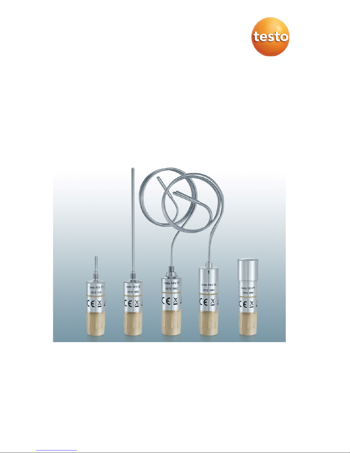
testo 191 data logger
Instruction manual
Page 2

Page 3

Contents
Contents
1 Safety and disposal.............................................................................. 5
1.1 About this document .............................................................................. 5
1.2 Security .................................................................................................. 5
1.3 Warning notices ..................................................................................... 7
1.4 Symbols ................................................................................................. 8
1.5 Transport ................................................................................................ 8
1.6 Disposal ................................................................................................. 8
2 Description of the instrument ............................................................... 9
2.1 Use ......................................................................................................... 9
2.2 testo 191 data logger variants .............................................................. 10
2.3 testo 191 data logger overview ............................................................ 10
2.4 Power supply ....................................................................................... 11
2.5 Programming and readout unit ............................................................ 11
2.6 testo 191 Professional software ........................................................... 12
3 Commissioning .................................................................................. 13
3.1 Installing the battery ............................................................................. 13
3.2 Positioning the distance adapter in the programming and readout unit
.......................................................................................................... 14
3.3 Positioning the data logger in the programming and readout unit ....... 15
3.4 Connecting the programming and readout unit to the PC via USB ..... 16
4 Operation ........................................................................................... 17
4.1 Bending flexible probe shafts ............................................................... 17
4.2 Changing the battery ............................................................................ 18
4.3 Installing the freeze-drying probe holder.............................................. 18
4.4 Aligning the can stand .......................................................................... 19
4.5 Installing the can and bottle attachment .............................................. 20
4.6 Mounting the retaining clamp .............................................................. 22
5 Maintenance ...................................................................................... 24
5.1 Cleaning the instrument ....................................................................... 24
5.2 Calibration ............................................................................................ 24
6 Technical data ................................................................................... 25
6.1 testo 191 T1 ......................................................................................... 25
6.2 testo 191 T2 ......................................................................................... 26
6.3 testo 191 T3 ......................................................................................... 26
Page 4

Contents
6.4 testo 191 T4 ......................................................................................... 27
6.5 testo 191 P1 ........................................................................................ 28
6.6 Large battery ....................................................................................... 29
6.7 Small battery........................................................................................ 29
6.8 Accessories and spare parts ............................................................... 30
Page 5

1 Safety and disposal
5
1 Safety and disposal
1.1 About this document
• The instruction manual is an integral part of the instrument.
• Keep this documentation to hand so that you can refer to it when
necessary.
• Always use the complete original instruction manual.
• Please read this instruction manual through carefully and familiarize yourself
with the product before putting it to use.
• Hand this instruction manual on to any subsequent users of the product.
• Pay particular attention to the safety instructions and warning advice in
order to prevent injury and damage to the product.
1.2 Security
General safety instructions
• Only operate the product properly, for its intended purpose, and within the
parameters specified in the technical data.
• Do not apply any force.
• Do not operate the instrument if there are signs of damage to the housing or
connected cables.
• Dangers may also arise from objects to be measured or the measuring
environment. Always comply with the locally valid safety regulations when
carrying out measurements.
• Do not store the product together with solvents.
• Do not use any desiccants.
• Only perform maintenance and repair work on this instrument that is
described in this documentation. Follow the prescribed steps exactly when
doing the work.
• The instrument is not explosion-proof and must not be used in potentially
explosive atmospheres.
• Maintenance work that is not described in this documentation must only be
carried out by trained service engineers.
Page 6

1 Safety and disposal
6
• Use only original spare parts from Testo.
Batteries
• Improper use of batteries may cause destruction of the batteries, injuries
due to current surges, fire or the escape of chemicals.
• Only use the battery supplied in accordance with the instructions in the
instruction manual.
• Do not charge batteries. Attempting to charge a non-rechargeable battery
may cause gas to be produced or heat to be generated. That may lead to
the escape of gases, an explosion and/or possibly to fire.
• Do not short batteries. If the positive (+) and negative (-) terminals of a
battery are directly connected to one another, the battery will be shorted.
For example, batteries can be shorted when you have them loose in your
pocket along with keys or coins. This may lead to the escape of gases and
the leakage of battery acid.
• Do not deform batteries. Batteries must not be squashed, drilled,
dismantled, pierced, modified or damaged in any other way. This may lead
to the leakage of battery acid, to the escape of gases and/or to an
explosion.
• Do not heat batteries above the permitted temperature or burn them. If a
battery is heated, this may lead to the leakage of battery acid and/or to an
explosion. Lithium batteries can, for instance, react very strongly in
combination with fire. This may involve battery components being emitted
with considerable power.
• Do not consume battery, risk of burns due to hazardous substances. Keep
new and used batteries away from children.
• In principle, contact with escaping battery components may present a risk
to health and to the environment. Adequate body and breathing protection
is therefore required when in contact with batteries that have peculiar
aspects (escaping contents, deformations, discolourations, dents or the
like).
• Do not leave batteries lying around loose once they have been unpacked. If
batteries that have been unpacked are left lying around loose, they can
easily short one another, particularly button cells. In some cases, this is very
dangerous because the batteries may heat up. This may lead to an
explosion.
• Always store batteries in a cool, dry place.
• Batteries must be disposed of in accordance with the local and country-
specific regulations. In order to prevent short circuits and the associated
heating, lithium batteries must never be stored unprotected in bulk.
Page 7

1 Safety and disposal
7
Appropriate measures against short circuits are for instance inserting the
batteries into the original packaging or a plastic bag, masking the poles or
embedding them in dry sand.
• Lithium batteries must be transported and shipped in accordance with the
local and country-specific regulations.
• Do not expose the batteries to heavy impacts, water or fire.
• Only use the batteries in environments with a maximum temperature of
+140 °C.
• Do not store unused batteries in the proximity of metal objects.
• Do not use any damaged batteries.
First-aid measures
• If there is any contact with the skin or eyes, the areas must be rinsed with
water for at least 15 minutes. If there is any contact with the eyes, a doctor
must be contacted in addition to the rinsing.
• If burns are caused, these must be treated appropriately. You are also
strongly advised to contact a doctor.
• Airways: Leave the room immediately when smoke development or gas
release is acute. Consult a doctor when amounts are larger and airways are
irritated.
• Swallowing: Rinse out mouth and surrounding area with water. Get medical
assistance immediately.
• In the event of contact with battery acid: rinse the affected areas thoroughly
with water and if necessary consult a doctor.
1.3 Warning notices
Always pay attention to any information denoted by the following warnings.
Implement the precautionary measures specified!
DANGER
Risk of death!
WARNING
Indicates possible serious injury.
Page 8
1 Safety and disposal
8
CAUTION
Indicates possible minor injury.
CAUTION
Indicates possible damage to equipment.
1.4 Symbols
Representa
tion
Explanation
Note: basic or further information
1
2
…
Action: several steps, the sequence must be followed
>
Action: one step or optional step
Result of an action
Requirement
Menu
Elements of the program interface
[OK]
Buttons of the program interface
1.5 Transport
• Always transport and store the data loggers and accessories in the Testo
cases.
1.6 Disposal
• Dispose of faulty and/or spent batteries in accordance with the valid legal
specifications.
• At the end of its useful life, deliver the product to the separate collection
point for electric and electronic devices (observe local regulations) or return
the product to Testo for disposal.
• WEEE Reg. No. DE 75334352
Page 9

2 Description of the instrument
9
2 Description of the instrument
2.1 Use
Testo guarantees the functionality of its products when used in
accordance with their intended purpose. This guarantee does not
apply to features of Testo products in combination with unauthorized
third-party products. Competitor products are not authorized by Testo.
As is common practice, Testo generally excludes support, warranty or
guarantee claims relating to functionality that has not been guaranteed
by Testo as part of the product offered. Claims of this kind shall also
be excluded in the event of improper use or handling of the products,
e.g. in combination with unauthorized third-party products.
The testo 191 data loggers are used to measure individual temperature and
pressure readings and measurement series.
The testo 191 data loggers measure and store temperature and pressure
readings which, with the aid of the configuration and readout unit and a USB
cable, are transmitted to the PC, where they can be read out and evaluated
using the testo 191 Professional software. The software also enables the data
loggers to be individually programmed and the readings analyzed and printed
out via a report and subsequently archived.
Application examples
The testo 191 T1, testo 191 T2, testo 191 T3, testo 191 T4 and testo 191 P1
data loggers are ideal for measuring temperature and pressure in order to
validate pasteurization and sterilization processes in autoclaves, containers and
freeze-drying systems.
In conjunction with the freeze-drying probe holder, the testo 191 T3 and
testo 191 T4 data loggers are also ideal for measuring the plate surface
temperature distribution in freeze-drying systems.
All testo 191 data loggers can also be used for various control measurements
of temperature and pressure within the defined temperature range.
Page 10
2 Description of the instrument
10
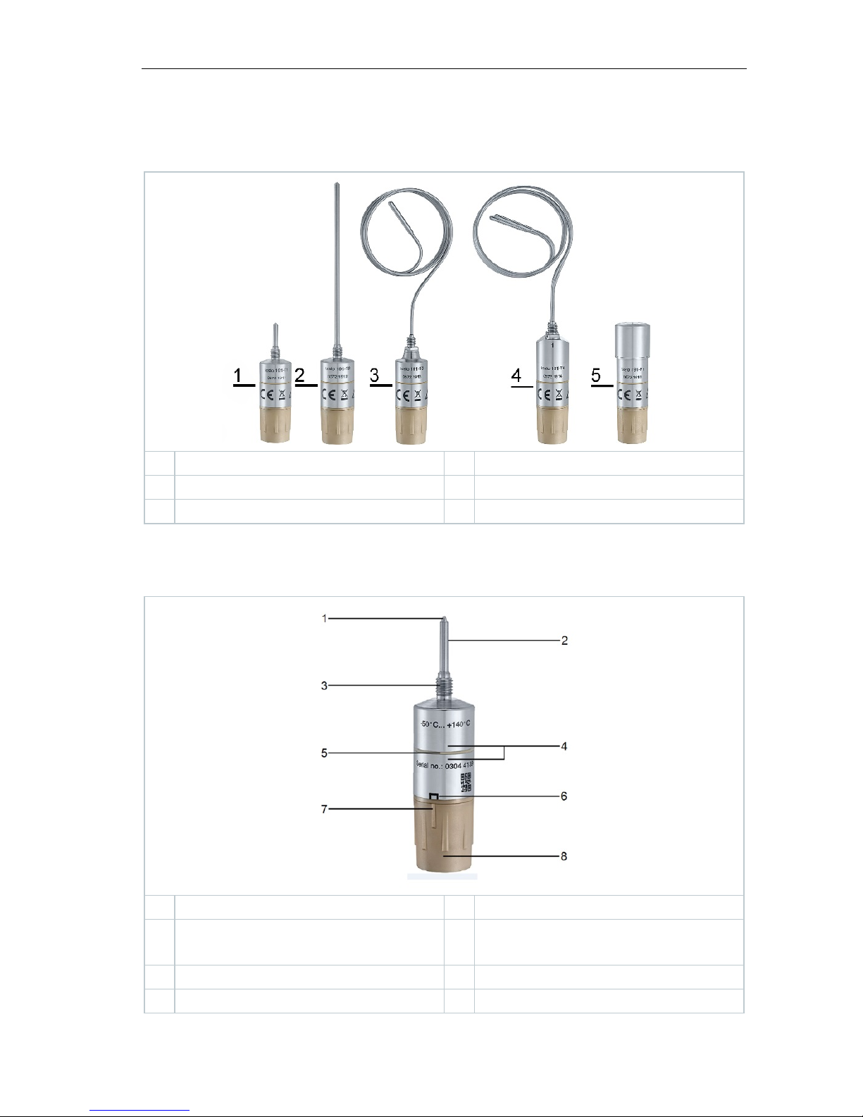
2.2 testo 191 data logger variants
1
testo 191 T1
2
testo 191 T2
3
testo 191 T3
4
testo 191 T4
5
testo 191 P1
2.3 testo 191 data logger overview
1
Probe shaft tip
2
Probe shaft
3
Thread
4
Programming and readout
contacts
5
Isolator ring
6
Position marking
7
Rib
8
Battery
Page 11

2 Description of the instrument
11
The testo 191 T4 and testo 191 P1 data loggers have no thread. For
the probe shaft dimensions of the testo 191 data loggers, please refer
to the technical data in Section 6,
Technical data
.
2.4 Power supply
Large and small battery types are available for all testo 191 data loggers. For
information on installing and changing the batteries, please refer to Section 3.1
Installing the battery and 4.2 Changing the battery. Section 6 contains the
Technical data for the batteries.
1
Large battery (1/2 AA)
2
Small battery (2 x button cell)
2.5 Programming and readout unit
Communication between the testo 191 data loggers and the testo 191
Professional software occurs exclusively via the programming and
readout unit. See Section 3.3,
Positioning the data logger in the
programming and readout unit
.
Page 12

2 Description of the instrument
12
Element Element
1
Micro USB port
2
Sliding bracket
3
Distance adapter
4
Communication contacts
The programming and readout unit is installed in the case. The data
loggers can also be transported in this.
2.6 testo 191 Professional software
The testo 191 Professional software can be used to program the testo 191 data
loggers via the programming and readout unit (e.g. measuring cycle,
measurement start, measurement stop, etc.) and read them. It also offers
calculation and analysis options for the measurement data acquired. The
separate testo 191 Professional software instruction manual (order no. 0970
1911) is available for this.
Page 13

3 Commissioning
13
3 Commissioning
3.1 Installing the battery
The testo 191 data loggers are supplied with a large battery as standard. The
data logger can therefore be used in the temperature range from -50 °C to
+140 °C.
The small battery, which can be used in the temperature range from 20 °C to +140 °C, can be purchased as an accessory.
WARNING
Danger of explosion!
Ambient temperature too hot!
- Do not place the batteries in an environment hotter than 140 °C.
- Do not expose the batteries to any microwave radiation.
An undamaged seal ring must be inserted in the groove provided and
another seal ring must be fitted below the thread.
1
Place battery on data logger and
press lightly.
2
Tighten battery by turning clockwise.
Avoid the use of force! Handtighten the battery.
Page 14

3 Commissioning
14
The rib on the battery is in the position marking.
ATTENTION
Inserting the battery incorrectly will cause damage!
Ingress of moisture!
- The rib must be positioned inside the position marking on the data
logger.
The service life of the batteries depends very much on the conditions
in the area of use. Under typical autoclave and freeze-drying
conditions (measuring cycle 10 s and service life 2 h/d), we
recommend replacing battery 0515 1900 after one year at the latest
and battery 0515 1901 after 50 days. Increased measuring cycles or
reduced measuring rates may result in a shorter service life.
Therefore, please pay attention to the battery level indicator in the PC
software.
3.2 Positioning the distance adapter in the
programming and readout unit
The data loggers are supplied with the appropriate distance adapters.
The testo 191 P1 data logger does not have a distance adapter and
can be placed in the programming and readout unit without using one.
1
Insert the distance adapter into the
socket first.
2
Push forward until the side brackets engage easily.
Page 15

3 Commissioning
15
3.3 Positioning the data logger in the
programming and readout unit
The testo 191 data loggers are supplied with the appropriate distance
adapter for the programming and readout unit. A battery must be
connected to the data logger for positioning in the station
Battery is connected
1
Insert appropriate distance adapter into the socket.
2
Insert data logger onto sliding
bracket.
3
Push the data logger in the direction
of the arrow and click it into place in
the distance adapter.
The data logger is properly inserted if
the isolator ring is between the two
communication contacts.
ATTENTION
The sliding bracket may break off if the pressure is too great!
- Use light pressure to insert the data logger in the socket.
Page 16

3 Commissioning
16
ATTENTION
Strong lateral pressure may cause the communication contacts on the
bottom of the socket to break off!
- First place the data logger on the sliding bracket and deposit it gently
onto the contacts.
3.4 Connecting the programming and
readout unit to the PC via USB
Please ensure that the case is securely positioned so that the case lid
cannot fall onto the cable.
The computer is started up and the testo 191 Professional software
is enabled.
The battery is connected to the data logger and is functional.
Data logger is placed on a socket of the programming and readout
unit.
1
Insert the micro USB plug into the programming and readout unit and
connect to the computer.
The software establishes a connection to the programming and
readout unit.
Successful connection to the
programming and readout unit is
indicated in green.
If the connection is shown in black, check that the programming and
readout unit is properly connected to your PC. In addition, please
check whether the isolator ring of the data logger is between the
contact pins, see
Positioning the data logger in the programming
and readout unit.
The data loggers can be programmed for the measurements using the
testo 191 Professional software.
Page 17

4 Operation
17
4 Operation
4.1 Bending flexible probe shafts
The testo 191 T3 and testo 191 T4 data loggers have flexible probe
shafts. The testo 191 T1 and testo 191 T2 data loggers are equipped
with rigid probe shafts, which must not be bent.
ATTENTION
Incorrect bending of the probe shafts!
Material fatigue and probe breakage!
- Begin bending the probe shafts only from a distance of 30 mm from the
housing material and 50 mm from the probe tip. Otherwise, the
mechanical stress caused by the housing and probe tip edge would be
too great.
- Do not use a clamp or any other tools to bend the probe shafts.
- The probe shaft of the data logger must not fall below the bending
radius of 50 mm. Small bending radii or rapid bending back and forth
result in material fatigue and premature probe breakage.
Page 18

4 Operation
18
4.2 Changing the battery
Before use, check that the battery is suitable for the operating temperature
range. For the operating temperature range of the battery types, please read
Section 6 Technical data.
1
Unscrew the battery from the data
logger by briefly turning to the left.
2
Remove battery from the data logger.
After removal of the battery, the data logger loses the information on
battery capacity.
Stored data is retained when the battery is replaced or if the battery
fails.
3
Connect new battery, see Section 3.1, Installing the battery.
The battery replacement must be confirmed in the testo 191
Professional software
. This can be done under the menu item
Programming of loggers.
4.3 Installing the freeze-drying probe holder
The freeze-drying probe holder can only be used in conjunction with the
testo 191 T3 and testo 191 T4 data loggers.
Page 19

4 Operation
19
ATTENTION
Damage to the instrument due to improper use!
- The freeze-drying probe holder can only be used in a freeze-drying
system.
1
Insert the probe shaft tip of the data
logger into the slot.
2
Place the puck with the probe tip at
the point to be measured on the
temperature plate.
3
Bend the probe shaft so that the freeze-drying probe holder is in full
contact with the support surface.
The data logger must be positioned in such a way that the freezedrying probe holder cannot slip.
4.4 Aligning the can stand
The can stand enables the testo 191 T1 data logger to be positioned in cans in
a way that is stable and safe. Depending on the size of the can, the can stand
can be bent into the correct position.
Page 20

4 Operation
20
1
Attach the retaining clamp to the wire
stand. The thread opening must point
upwards.
2
If necessary, bend the wire stand into the correct position.
3
Rotate the testo 191 T1 data logger clockwise onto the retaining
clamp.
4
Position the can stand with the
testo 191 T1 data logger in the can.
The can stand can also be used as a device to make the position of
the testo 191 T1 data logger more stable.
4.5 Installing the can and bottle attachment
Used in conjunction with the testo 191 T2 data logger, the can and bottle
attachment enables the core temperature of food in cans and bottles to be
measured during a pasteurisation process.
Page 21

4 Operation
21
No additional tools are required to install the can and bottle
attachment on cans or bottles.
1
Lightly press the can and bottle attachment onto the insertion
position on the can or bottle.
2
The retaining thread penetrates through the top of the can or bottle
via a light tap on the can and bottle attachment head.
3
The can and bottle attachment can now be rotated in a clockwise
direction into the can or bottle.
Before inserting the probe shaft through the opening, make sure that
the fastening screw on the head is not fully screwed in, but is slightly
undone.
4
Slightly unscrew the fastening screw
on the head by turning it in a
counterclockwise direction.
Page 22

4 Operation
22
5
The probe shaft can be guided
through the opening of the can and
bottle attachment into the can or
bottle.
6
The fastening screw on the head of
the can and bottle attachment can be
tightened by turning it in a clockwise
direction.
4.6 Mounting the retaining clamp
The testo 191 T1, testo 191 T2 and testo 191 T3 data loggers have a thread on
the probe shaft, which is intended for attaching the retaining clamp. The data
logger can therefore be attached in systems or loading baskets without the use
of adhesive tape. The retaining clamp can be used multiple times.
Page 23

4 Operation
23
1
With the thread in front, push the retaining clamp over the probe
shaft.
2
Screw the retaining clamp clockwise
onto the thread on the data logger.
3
A fixing material (cable tie, wire, etc.)
can be fed through the opening of the
retaining clamp.
4
Secure the data logger to an object (e.g. metal grid).
No additional tools are required to attach the retaining clamp. Materials
such as cable ties or wires are not included in the delivery.
Page 24

5 Maintenance
24
5 Maintenance
5.1 Cleaning the instrument
• If the housing of the instrument is dirty, clean it with a damp cloth or a
brush.
• Do not use any aggressive cleaning agents or solvents! Mild household
cleaning agents and soap suds may be used.
5.2 Calibration
The testo 191 data loggers feature a high level of accuracy. In order to maintain
this accuracy of the measurement results, Testo recommends calibrating the
instrument once a year. This service can be carried out by Testo Industrial
Services GmbH.
If you have any questions about other services related to calibration,
validation and qualification, please contact Testo Industrial Services
GmbH. Give Testo Industrial Services GmbH a call on +49 7661
90901-0 or go to the website www.testotis.com.
Page 25

6 Technical data
25
6 Technical data
6.1 testo 191 T1
Feature Value
Order no.
0572 1911
Measurement parameter
Temperature (°C / °F / K)
Probe type
PT1000
Measuring range
-50 °C to +140 °C
Accuracy 0.1 °C (-40 °C to +140 °C)
0.2 °C (-50 °C to -40 °C)
Resolution
0.01 °C
Operating temperature 0 °C to +140 °C
Storage temperature -20 °C to +50 °C
Battery type
See Large battery / Small battery
Battery life
See Large battery / Small battery
Dimensions without probe
shaft (D x H)
(with large battery)
Ø 20 mm x 59 mm
Dimensions without probe
shaft (D x H)
(with small battery)
Ø 20 mm x 40 mm
Probe shaft dimensions
(D x H)
Ø 3 mm x 25 mm
Weight
47 g
Housing material
Stainless steel 316L/WNR. 1.4404/SUS 316L
Measuring cycle
1 s to 24 h
Measurement data memory
60,000 readings
Guideline 2014/30/EU (EMC)
2011/65/EU (RoHS)
EU declaration of conformity You can find the EU declaration of conformity
on the Testo website www.testo.com under
the product-specific downloads.
Page 26

6 Technical data
26
6.2 testo 191 T2
Feature Value
Order no.
0572 1912
Measurement parameter
Temperature (°C / °F / K)
Probe type
PT1000
Measuring range -50 °C to +140 °C
Accuracy 0.1 °C (-40 °C to +140 °C)
0.2 °C (-50 °C to -40 °C)
Resolution 0.01 °C
Operating temperature -50 °C to +140 °C
Storage temperature
-20 °C to +50 °C
Battery type
See Large battery / Small battery
Battery life
See Large battery / Small battery
Dimensions without probe
shaft (D x H)
(with large battery)
Ø 20 mm x 59 mm
Dimensions without probe
shaft (D x H)
(with small battery)
Ø 20 mm x 40 mm
Probe shaft dimensions (D x
H)
Ø 3 mm x 115 mm
Weight
48 g
Housing material
Stainless steel 316L/WNR. 1.4404/SUS 316L
Measuring cycle
1 s to 24 h
Measurement data memory
60,000 readings
Guideline 2014/30/EU (EMC)
2011/65/EU (RoHS)
EU declaration of
conformity
You can find the EU declaration of conformity
on the Testo website www.testo.com under the
product-specific downloads.
6.3 testo 191 T3
Feature Value
Order no.
0572 1913
Measurement parameter
Temperature (°C / °F / K)
Probe type
PT1000
Page 27

6 Technical data
27
Feature Value
Measuring range
-50 °C to +140 °C
Accuracy 0.1 °C (-40 °C to +140 °C)
0.2 °C (-50 °C to -40 °C)
Resolution
0.01 °C
Operating temperature
-50 °C to +140 °C
Storage temperature
-20 °C to +50 °C
Battery type
See Large battery / Small battery
Battery life See Large battery / Small battery
Dimensions without probe
shaft (D x H)
(with large battery)
Ø 20 mm x 63 mm
Dimensions without probe
shaft (D x H)
(with small battery)
Ø 20 mm x 45 mm
Probe shaft dimensions
(D x H)
Ø 1.5 mm x 775 mm
Probe shaft tip dimensions
(D x H)
Ø 3 mm x 25 mm
Weight
61 g
Housing material
Stainless steel 316L/WNR. 1.4404/SUS 316L
Measuring cycle 1 s to 24 h
Measurement data memory 60,000 readings
Guideline 2014/30/EU (EMC)
2011/65/EU (RoHS)
EU declaration of conformity You can find the EU declaration of conformity
on the Testo website www.testo.com under
the product-specific downloads.
6.4 testo 191 T4
Feature Value
Order no.
0572 1914
Measurement parameter
Temperature (°C / °F / K)
Probe type
2 x PT1000
Measuring range -50 °C to +140 °C
Accuracy 0.1 °C (-40 °C to +140 °C)
0.2 °C (-50 °C to -40 °C)
Resolution 0.01 °C
Page 28

6 Technical data
28
Feature Value
Operating temperature
-50 °C to +140 °C
Storage temperature
-20 °C to +50 °C
Battery type
See Large battery / Small battery
Battery life
See Large battery / Small battery
Dimensions without probe
shaft (D x H)
(with large battery)
Ø 20 mm x 72 mm
Dimensions without probe
shaft (D x H)
(with small battery)
Ø 20 mm x 53 mm
Probe shaft dimensions
(D x H)
Ø 1.5 mm x 775 mm
Probe shaft tip dimensions
(D x H)
Ø 3 mm x 25 mm
Weight
92 g
Housing material
Stainless steel 316L/WNR. 1.4404/SUS 316L
Measuring cycle
1 s to 24 h
Measurement data memory 30,000 readings per channel
Guideline 2014/30/EU (EMC)
2011/65/EU (RoHS)
EU declaration of conformity You can find the EU declaration of conformity
on the Testo website www.testo.com under
the product-specific downloads.
6.5 testo 191 P1
Feature Value
Order no.
0572 1916
Measurement parameter Pressure (mbar / bar / hPa / kPa / psi / kg/cm²
/ Torr)
Probe type
Piezoresistive sensor
Measuring range
1 mbar to 4 bar
Accuracy
± 20 mbar
Resolution 1 mbar
Operating temperature 0 °C to +140 °C
Storage temperature
-20 °C to +50 °C
Battery type
See Large battery / Small battery
Battery life
See Large battery / Small battery
Page 29

6 Technical data
29
Feature Value
Dimensions without probe
shaft (D x H)
(with large battery)
Ø 22 mm x 83 mm
Dimensions without probe
shaft (D x H)
(with small battery)
Ø 22 mm x 64 mm
Weight
91 g
Housing material
Stainless steel 316L/WNR. 1.4404/SUS 316L
Measuring cycle
1 s to 24 h
Measurement data memory
60,000 readings
Guideline 2014/30/EU (EMC)
2011/65/EU (RoHS)
EU declaration of conformity You can find the EU declaration of conformity
on the Testo website www.testo.com under
the product-specific downloads.
6.6 Large battery
Feature Value
Order no.
0515 1901
Housing material PEEK
Output 3.6 V (800 mAh)
Battery type
1/2 AA lithium battery
Field of application -50 °C to +140 °C,
1 mbar to 4 bar (abs.)
Storage temperature
-20 °C to +50 °C
Dimensions
Ø 20 mm; length 31.3 mm
Battery life (measuring cycle 10
seconds at 121 °C)
2,500 operating hours
6.7 Small battery
Feature Value
Order no.
0515 1900
Housing material
PEEK
Output 3.6 V (48 mAh)
Battery type 2 x button cell
Page 30

6 Technical data
30
Feature Value
Field of application -20 °C to +140 °C,
1 mbar to 4 bar (abs.)
Storage temperature
-20 °C to +50 °C
Dimensions
Ø 20 mm; length 12.6 mm
Battery life (measuring cycle 10
seconds at 121 °C
250 operating hours
6.8 Accessories and spare parts
Description Order no.
testo 191 T1, HACCP temperature data logger including
large battery, long distance adapter for programming
and readout unit and calibration protocol
0572 1911
testo 191 T2, HACCP temperature data logger including
large battery, long distance adapter for programming
and readout unit and calibration protocol
0572 1912
testo 191 T3, HACCP temperature data logger including
large battery, long distance adapter for programming
and readout unit and calibration protocol
0572 1913
testo 191 T4, HACCP temperature data logger including
large battery, short distance adapter for programming
and readout unit and calibration protocol
0572 1914
testo 191 P1, HACCP pressure data logger including
large battery and calibration protocol
0572 1916
Small battery 0515 1901
Large battery 0515 1900
Case small
0516 1901
Case large
0516 1902
Testo 191 Professional software
0554 1911
Retaining clamp (pack of 5)
0554 0297
Freeze-drying probe holder
0554 1907
Can tripod 0554 1906
Can and bottle attachment 0554 0458
Distance adapter short
0554 0298
Distance adapter long
0554 0299
ISO calibration certificate (temperature)
0520 0141
DAkkS calibration certificate (temperature)
0520 0281
Page 31

6 Technical data
31
Description Order no.
ISO calibration certificate (pressure)
0520 0025
DAkkS calibration certificate (pressure)
0520 0215
For further accessories and spare parts, please refer to the product catalogues
and brochures or look up at
www.testo.com.
Page 32

0970 1911 en 01
Testo SE & Co. KGaA
Testo-Strasse 1, D-79853 Lenzkirch,
Germany
Phone: +49 7653 681-0
Fax: +49 7653 681-100
E-mail: info@testo.de
Internet: www.testo.com
 Loading...