

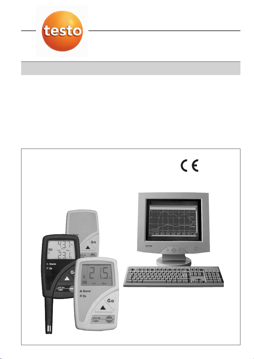
testo 177
Instruction manual en

Copyright
All rights reserved.
No part of this publication may be reproduced, stored in a
retrieval system, or transmitted, in any form or by any means,
electronic, mechanical, photocopying, recording, or otherwise,
without the prior permission of Testo AG.
We reserve the right to modify the technical data contained in the
descriptions, data and graphics in this documentation.
Testo AG
Postfach 11 40
79849 Lenzkirch
Germany
Microsoft®, Windows®, Excel® and Internet Explorer® are
registered trademarks of the Microsoft Corporation.
2
Introduction / General information
Introduction
Dear Customer
Thank you for purchasing a Testo product. We hope you will enjoy the benefits of this product for a
long time to come and that it will help you with your work.
Please take the time to read the instruction manual carefully and make sure you become familiar with
how the instrument operates before using it.
If there are any problems, which you cannot solve yourself, please contact our Customer Service
Department or your nearest distributor. We will do our best to help you quickly and competently to
reduce downtimes.
General information
Warnings and particularly important information, which has to be observed when working with this
product, are highlighted in this instruction manual as follows
Warnings
Warnings are marked by a warning symbol. The appropriate Warning title indicates the danger level:
Warning! means death or serious physical injury may occur if the specified safety
measures are not carried out.
Caution! means minor physical injury or damage to property may occur if the specifed
Warning
titie!
Important information
Particularly important information is highlighted in this instruction manual by an exclamation mark.
safety measures are not carried out.
Read all the warnings carefully and carry out the specified safety measures to avoid
danger.
Standards
The conformity certificate confirms that this product fulfills the guidelines in accordance with
89/336/EWG.
3

Contents
Copyright ..........................................................2
Introduction / General information ....................3
Contents............................................................4
1. Basic safety instructions ..................................6
2. Intended use ....................................................7
3. Initial operation..................................................8
4. Display and control elements ..........................9
4.1 Display ........................................................................9
4.2 LED functions ............................................................10
4.3 Display sequence ......................................................11
4.4 Button functions ........................................................11
5. Mounting ........................................................12
5.1 Mounting the wall holder ..........................................12
5.2 Securing the data logger with a lock ........................12
5.3 Transportable unit ......................................................12
6. Connecting probes/switch ..............................13
7. Programming ..................................................14
7.1 Installing software ......................................................14
7.2 Connecting data logger to PC ..................................14
7.3 Setting up the connection ........................................15
7.4 Opening the connection ............................................16
7.5 Programming the data logger ....................................17
7.6 Closing the connection ..............................................24
8. Reading out data ............................................25
9. Changing the battery ......................................26
10. Error messages ..............................................27
4

Contents
11. Technical data ................................................28
11.1 testo 177-T1 ..............................................................28
11.2 testo 177-T2 ..............................................................29
11.3 testo 177-T3 ..............................................................30
11.4 testo 177-T4 ..............................................................31
11.5 testo 177-H1 ..............................................................32
11.6 Battery life ................................................................33
12. Accessories/Spare parts ................................34
5
1. Basic safety instructions
Please read through the following safety instructions carefully:
Avoiding electricity:
Never use the instrument and external probes to measure on or near live parts if the instrument is
not expressly approved for current and voltage measurement!
Product safety:
Prior to each measurement, check if the connections are connected properly via the blind plug and
if the right probe is correctly inserted. Otherwise the protection class specified in the Technical data
cannot be guaranteed.
The logger should only be operated within the parameters specified in the Technical data.
Please handle the logger with care.
The instrument should only be opened if expressly described in the instruction manual for
maintenance purposes.
Force should never be applied!
Only for testo 177-4
The probe sockets in testo 177-4 are not isolated from one another. Please take note of this when
using surface probes with a non-insulate thermocouple.
Disposal:
Please dispose of spent batteries responsibly.
You can return your logger directly to us at the end of its service life. We will dispose of it
responsibly.
6

2. Intended use
The testo 177 data loggers are used to save and read out separate readings and measurement
sequences. The readings are measured, saved and transmitted to a PC, to the testo 575 fast printer
or to the testo 580 data collector per infrared using testo ComSoft software.
Applications
testo 177-T1
Fast and affordable temperature monitoring
in refrigeration and deep freeze sector:
during transport, in refrigerated rooms,
in display cabinets, in containers
Fulfills guidelines in accordance with
EN 12830 standards *
testo 177-T2
Temperature monitoring with display:
during transport, in glass cabinets,
in refrigerated rooms, in containers,
in domestic housing
Fulfills guidelines in accordance with
EN 12830 standards *
testo 177-T3
Temperature logger with display and switch
(door contact) for monitoring transport:
transport monitoring, refrigerated room
monitoring, in containers, in warehouses
Fulfills guidelines in accordance with
EN 12830 standards *
* In accordance with EN 12830, please ensure that a regular check and calibration in accordance with
EN 13486 (recommendation: once a year) is carried out on this instrument. Please contact us for
more detailed information.
testo 177-T4
Fast measurement of high temperatures:
during production processes, in laboratories
in heating installation sector, in containers
in domestic housing
testo 177-H1
Monitoring of humidity and temperature
values with external temperature and dew
point measurement
in domestic housing, in the pharmaceutical
sector, in museums, in warehouses,
in industry
Only for testo 177 - T3
The following components of the product are designed for continuous contact with
foodstuffs in accordance with the regulation
(EG) 1935/2004:
The measurement probe up to 1 cm before the probe handle or the plastic housing. If
provided, the information about penetration depths in the instruction manual or the mark(s)
on the measurement probes should be noted.
7

3. Initial operation
Type 177-T1 177-T2 177-T3 177-T4 177-H1
Start criterion Key start
Measuring rate 5 Min. 5 Min. 5/1 Min.* 3 Sek. 1 Min.
Stop criterion Wraparound Until memory Wraparound
Alarm values Respective measuring range full-scale values (See Technical data)
Display -On
LEDs Status led (green): Off / Alarm led (red): On
Measurement channels All channels switched on **
Fast printer- / Stop: Switched on
data collector function New programming: Switched on
Protocol name testo177-{Type}_{Serial number}
* Depending on event: switch (e.g. door contact) open or not connected/switch closed
** testo 177-T4: T/C -Type “K” programmed
The data loggers have the defaults below:
memory is full memory
The data logger with the above factory defaults can be used
immediately.
If you wish to use other measurement criteria, you will have to
program your data logger in accordance with your requirements
using testo ComSoft software (See 7. Programming, P. 14).
External probes can be attached to many of the data loggers (See
6. Connecting probes, S. 13).
8
Readings
Top alarm value
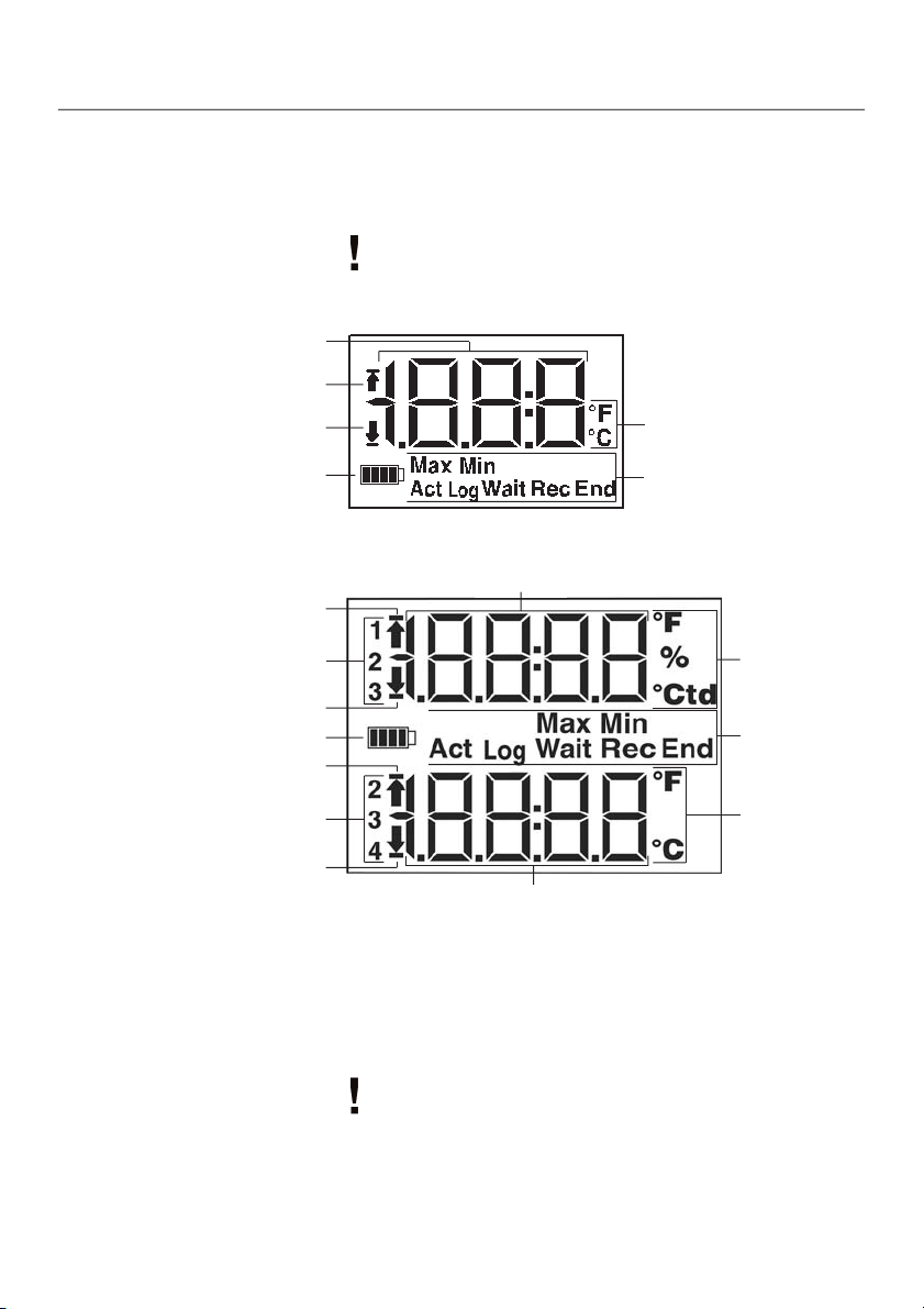
4. Display and control elements
4.1 Display
The display function can be activated/deactivated via the testo
ComSoft
a display.
testo 177-T2:
software. The testo 177-T1 data logger do not have
Bottom alarm value
Battery capacity
testo 177-T3, testo 177-T4, testo 177-H1:
Readings
Top alarm value
Channels
Bottom alarm value
Battery capacity
Top alarm value
Channels
Bottom alarm value
Readings
* Reading information:
Max = highest reading, Min = lowest reading, Act = Intermediate reading (is shown in display but is
not saved), Log = saved reading
Status information:
Wait
= Waiting for program to start,
program is finished
Rec
= Measuring program is running,
Units
Reading and status
information *
Units
Reading and
status
information *
Units
End
= Measuring
Due to technical reasons, the display speed of the liquid
crystals slows down at temperatures below 0 °C
(approx. 2 s at -10 °C, approx. 6 s at -20 °C). However, this
does not have any influence on the accuracy of the
measurement.
9
4. Display and control elements
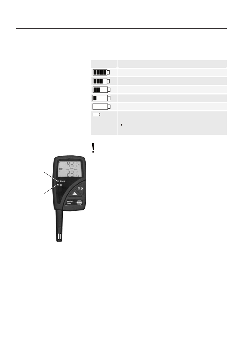
4.2 LED functions
2
Reference values (See 11.6 Battery
life, P. 33)
3
The battery symbol is updated
when:
- the wraparound memory is full
- measurement program is
started/ended
Record
- In
Once a day
- the
if last measurement was more than
24 hours ago
mode:
GO
button is pressed:
Alarm led
(red LED)
Status led
(green LED)
Symbol
3
Capacity
75-100%
50-75%
25-50%
10-25%
<10%
OFF
Battery empty (measuring program was stopped)
Reading out data and changing battery (See
9. Changing battery, P. 26)
The LED functions can be switched on/off via
testo ComSoft software.
In all modes:
The Alarm led flashes three times every 15 seconds if the
remaining battery capacity is less than10% (even if Alarm led is
deactivated).
Wait
mode and
Key start
start criterion programmed:
The status led flashes five times if the GObutton is kept pressed
for approx. 3 s (even if the Status led is deactivated).
It is confirmation that the measuring program was started and
that the data logger is now in the
Record
mode:
Record
mode.
The Alarm led flashes once every 15 s if alarm values have been
exceeded (only if Alarm led is activated).
The Status led flashes once every 15 s (only if the Status led is
activated).
It is confirmation that the measuring program is running.
The Status led flashes five times if the GObutton is kept pressed
for approx. 3 s (even if Status led is deactivated).
It is confirmation that a time mark has been set.
10
4. Display and control elements
4.3 Display sequence
Depending on the mode, different information can be displayed in
the data loggers with display. You will find a detailed description of
the information which can be called up in the short version of the
instruction manual enclosed with every data logger.
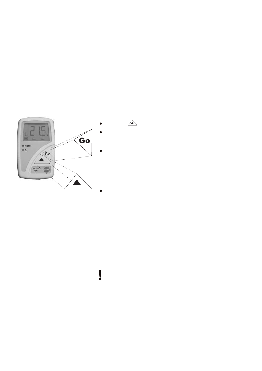
4.4 Button functions
In all modes in data loggers with display:
Press the button to switch between the displays.
Press the GObutton to activate an intermediate measurement.
Wait
mode and
Press the GObutton for approx. 3 s to start the measuring
program.
- The measuring program starts,
(if available) and the Status led flashes five times.
Record
Press the GObutton for approx. 3 s to set a time mark.
- The Status led flashes five times.
Time mark: This function enables you to monitor and read
out/print out the memory content from a specified point in time
(
time mark
readings from
The readings from
read out on the testo 575 fast printer or the testo ComSoft
software.
The readings from
testo 580 data collector.
Only one time mark can be set. If the GObutton is pressed for
approx. 3 seconds in the
is deleted and a new time mark is set up.
- The readings (max./min. values, exceeding of alarm values)
are shown in the display (if available) from the set time mark.
Key start
mode:
) without having to reprogram the data logger. The
Start(All readings
start criterion programmed:
Record
) are also saved.
Start(All readings
Start(All readings
Record
) or
) can be read out on the
mode, the existing time mark
appears in the display
From time mark
can be
11
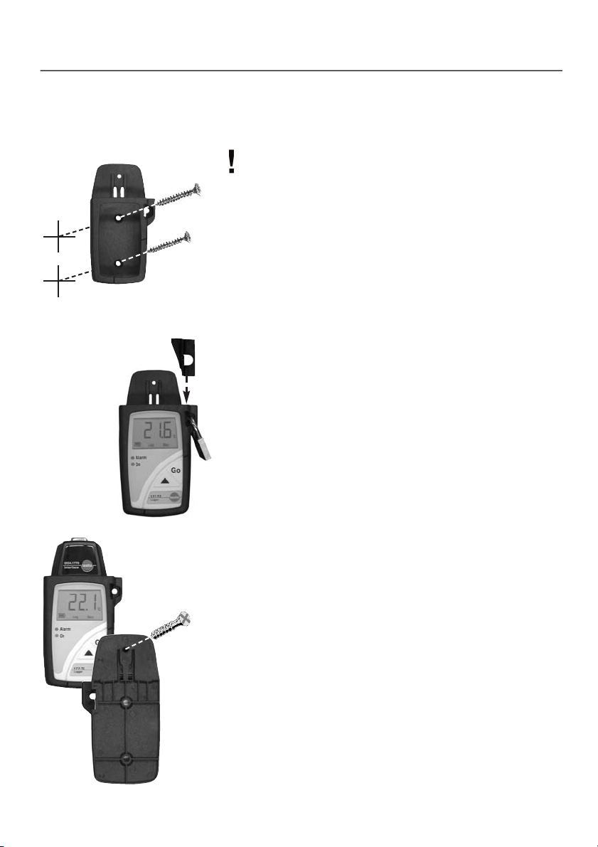
5. Mounting
5.1 Mounting the wall holder
Mounting materials (e.g. screws, dowels) are not included.
1 Position the wall holder at the required location.
2 Using a pencil or similar, mark where the fixing screw is to go.
3 Prepare the area for mounting (e.g. drill a hole, put in dowel).
4 Mount the wall holder using a screw which fits.
5.2 Securing the data logger with a lock
1 Insert the data logger into the wall holder.
2 Place the retainer key in the wall holder.
3 Attach the lock to the wall holder (Accessory: Part no.
0554 1755).
12
5.3 Transportable unit
A unit can be made out of the wall holder, logger and the
interface to make transport or dispatch easier.
1 Push the data logger into the wall holder.
2 Push the interface onto the wall holder.
3 Secure the unit by connecting the wall holder and the interface
using the screw supplied.

Warning!
6. Connecting probes/switch
Observe the following points when connecting the probes to the
data logger and to the measurement points:
Observe poles of plug.
Insert the plugs firmly into the connections to guarantee that
they are properly in place. Force should not be used.
Ensure that the plugs are firmly attached to the data logger or
that the connections are in place with a blind plug.
Ensure that the probe is positioned properly to avoid disturbing
influences on the measurement.
testo 177-T3:
Use the enclosed twin-wire cable to connect the switch (door
contact). Connect a potential-free button or switch to it.
False connection!
Electric shock! Damage to data logger!
Do not apply electrical signal to cable and avoid contact with live parts.
Only one potential-free contact should be connected.
Measuring rate
both cables are not connected with one another.
Measuring rate Door
cables are connected with one another (See page 24).
The data logger requires slightly more energy if the contact is
electrically closed. It is recommended to select the contact so
that it is electrically open most of the time.
testo 177-T4:
Ensure that each respective configured probe is connected to
the socket (via testo ComSoft software).The numbers of the
connections are printed on the housing!
is activated if the contact is open electrically i.e. if
if the contact is closed electrically i.e. if both
13

7. Programming
7.1 Installing software
In order to program your data logger in accordance with your
individual needs, you will need a PC on which the testo ComSoft
software is installed.
You will find instructions on the installation and operation of the
software in the testo ComSoft instruction manual.
Continue with 7.2 Connecting data logger to PC, P. 14 once
the software is successfully installed.
7.2 Connecting data logger to PC
You will need a free serial interface (RS232) or a USB interface
to connect the data logger interface to your PC.
Proceed with Step 1 if using a serial interface.
The USB driver must already be installed in the PC when
using a USB interface. The driver and installation instructions
are enclosed with the USB interface. Proceed with Step 1
once successfully installed.
1 Connect the serial connection cable or USB connection cable
of the interface to your PC.
2 Connect the interface to the connection cable.
3 Insert the interface in the desk-top holder.
4 Place the logger in the desk-top holder.
The interface can be placed directly in the wall holder. In this
way, the data can be read out directly on location.
Ensure that the interface is completely plugged on and
snapped into place. Otherwise the connection is not
guaranteed.
5 Start the testo ComSoft software.
14

7. Programming
7.3 Setting up the connection
1 Start testo ComSoft software.
2 Select
-
- The connection to the data logger found is set up
-or-
2 Select
- The
Instrument > Autodetect...
Autodetect
automatically and the name of the connection appears in the
Data
opens.
window.
Instrument> New device
New device setup wizard
.
.
opens.
3 Select
4 Select the interface in
5 Enter a name for the connection and click on
testo175-177
connected your data logger to your PC and click on
in Device selection and click on
Connection
, with which you have
Finish
Next
Next
.
.
.
15

7. Programming
Confirmation of battery change
- If the data logger is used for the first time or the data logger
battery has been changed, the
Enter the date when the battery was changed.
Enter the temperature range in which you will use the data
logger and confirm with OK.
- The connection to the data logger is set up. The name of the
connection appears in the
New battery
Data
window.
window opens.
7.4 Opening the connection
Click twice on the connection, which you want to open, in the
Data
window.
- If a protocol is saved in the data logger, the protocol symbol
and the title appear under the opened connection.
16
The readings saved in the data logger are not transmitted to
the PC when the connection is opened. Carry out the following
to transmit the readings:
Click twice on the title of the protocol (See testo ComSoft
software instruction manual).
Use one connection for several data loggers
You can connect different data loggers once a connection has
been set up. The connection must be closed when changing
the data logger and then opened again for the new data
logger. Otherwise, it cannot be identified by the software (See
7.6 Closing the connection, P.24).

7. Programming
7.5 Programming the data logger
Any readings in the data logger are deleted if the data logger
is programmed.
Read out any data from the data logger which may exist
before programming
(See testo ComSoft software instruction manual).
Select
Instrument> Device control
This function is only activated if the name of the connection is
highlighted. If this is not the case:
First click on the name of the connection so that it is
highlighted and then select
- The window for programming the data logger opens.
.
Instrument> Device control
.
Window selection
You will find a bar on on the left side in which the available
windows are shown. Click to select.
Programming recommendation
It is recommended to carry out programming first in the
and
Settings
windows and then in the
Program window
Probes
.
17

7. Programming
Instrument
You can read general information on the data logger in the
Instrument
Protocol
window.
This window is a pure information window. Programming is not
possible.
18
You can read information from the protocol currently stored in the
data logger in the
values
and
This window is an information window. Programming is not
possible.
Protocol
Since time mark
window.You can choose to display
.
All

7. Programming
Probes
Probes:
Activate the probes available or deactivate them.
Unit:
Displays the set unit for the respective channel.
You cannot change the unit in this window, but in the
window.
Settings
LL:
The lower alarm limit for the channels is entered here.
UL:
The upper alarm limit for the channels is entered here.
Name:
Enter a name for the channel here.
19

7. Programming
Settings
Date and time:
The set date and the time in the data logger are shown.
Select
Synchronize
data logger with the clock in your PC.
Date/Time can only be synchronized when the data logger is
in the
Wait
or
to synchronize the date and the time in the
End
mode.
20
Temperature:
Select the required temperature unit for the temperature
channels (°Cor °F).
testo 575/ testo 580
Select whether the data logger is to be newly programmed
(
New programming
printer and the testo 580 data collector.
- Function:
) and stopped (
Stop
) via the testo 575 fast

7. Programming
Humidity calibration (
Select between
If
Custom
- The
Display functions:
is selected, the
Click on
Carry out humidity calibration using the control and adjustment
set (Part no. 0554.0660). Follow the instructions in the
Instruction Manual for the Control and Adjustment Set.
Select whether the LEDs, the
on are to be activated in the data logger.
Only the data display is deactivated when the display is
switched off. Status information on mode and battery capacity
are always shown.
Custom ...
Humidity calibration
testo 177-H1
Factory defaults
Custom ...
.
window opens.
only):
or
Custom
button is activated.
Alert led
, Status led and
.
Display
Enable limit signal output
From ComSoft Version 3.4 on, the external alarm signal output
testo 581 can be activated if connected to a data logger.
21

7. Programming
Program
Start criterion:
Select the required criterion for the start of the program.
You have the choice between
PC Start
If
can enter/select the required date/time.
.
Date/Time
is chosen, an additonal field appears in which you
Date/Time, Key start
and
22
Measuring rate:
Select the time cycle in which the measurements are to be
carried out.
You can choose between sec (seconds),
and d(days).
The smallest/largest measuring rate differs depending on the
instrument type (Refer to 11. Technical data, P. 28).
Measuring rate Door (
Select the time rate in which the measurements are to take
place, if the contact is closed electrically.
Stop criterion:
Select the required criterion to stop the measuring program.
You can choose between
Wraparound memory
testo 177-T3
Until memory is full, No. of logs
and
Date / Time.
only):
min
(minutes), h(hours)
,

7. Programming
It is only possible to select
selected as
additional field will appear in which the number of
measurements required can be entered.
testo 177-T3:
door contact is activated.
Start criterion
Date/Time
Date/Time
. If you choose
is not possible as
if
Date/Time
No. of logs
is also
an
Stop criterion
if
Duration:
Indicates running time of program calculated on the basis of the
values for
If the
until the memory is full is calculated.
Start criterion, Measuring rate
Wraparound
stop criterion is selected, the length of time
and
Stop criterion
.
Estimated battery life:
Indicates estimated battery life.
Title:
Enter a Title for the measuring program.
Maximum 24 characters can be entered.
The title of the measuring program is accepted into the testo
ComSoft
appear at the top of the printout when the protocol is printed on
the testo 575 printer.
software when the data logger is read out. The title will
Comments:
Additional information on the measuring program can be
entered here.
The entered text is printed on the testo 575 printer printout. Up
to 96 characters can be entered. The fast printer automatically
enters return after every 24 characters.
Send to:
Activate the function by clicking on the selection window and
enter an e-mail address in the text box.
Once the measurement protocol has been opened in the testo
ComSoft
The entered email address and the log are automatically saved in
your e-mail.
software, you can send it by e-mail via
System requirement for this function:
Microsoft Windows 95 or newer and
Microsoft Internet Explorer 5.0 or newer.
File > Send
...
23

7. Programming
Start and Stop:
Click on
This function can only be selected if
has been selected as
Click on
This function can only be selected if a measurement is
running.
Programming ended
Click on
A measuring program can only apply in the data logger if it is
in the
If a measurement is running (
- The
programming.
Start
to start a measuring program..
PC start
Start criterion
Stop
to end a measuring program.
Apply
to transmit the programming to the data logger.
Wait
or
End
mode.
Finish the measurement by clicking on
Programming data
window opens to confirm the following
Record
.
mode):
Stop.
24
7.6 Closing the connection
1 Click on the connection you wish to close with your right
mouse button in the
2 Select
- The connection to the data logger is closed.
Close
Data
window.
.

8. Reading out data
You have three options to read out data from the data logger:
1. Via testo ComSoft software. Data is transmitted directly to a
PC.
Please read the Instruction manual on the testo ComSoft
software.
testo ComSoft software is available in 2 versions with the
following range of functions:
testo ComSoft 3 Basic (0554.1758)
- Programming and reading out the testo 174,
testo 175 and testo 177 data loggers
- Display and printout as table or diagram
- Data export (e.g. in Microsoft Excel)
- Automatic search for instrument driver when started
(Auto Detect)
testo ComSoft 3 Professional (0554.0830)
like testo ComSoft 3 Basic, but with the following additional
features:
- Programming and reading out other Testo instruments such
as testo 400, testo 650, etc.
- Display and printout as number box, histogram, form, analog
instrument, parametric graph
- Data management function
- Analysis functions (compensation curve, mean function)
- Selection of different printing heads for table and graph
printouts
- Adaptation of menus and range of functions
- Developer ToolBox with functions to incorporate the instrument
driver in non-Testo software
2. Via the testo 580 data collector.
Data can then be read out via testo Comsoft software.
For more information, refer to the testo 580 Instruction
manual.
3. Printout via testo 575 fast printer
For more information, refer to the testo 575 Instruction
manual.
25

9. Changing the battery
1 Please read out the saved data before changing the battery.
See testo ComSoft software Instruction manual
If it is not possible to read out the saved data due to low
battery capacity, please carry out the following:
2 Remove the screw at the back of the data logger using a small
crosstip screwdriver.
3 Using a screwdriver, lift the back wall at the bottom of the data
logger and then remove from data logger 1.
4 Attach the jumper (included with spare battery) to the plug
connector beside the connection for the battery 2.
The inserted jumper prevents the memory from being deleted
or written over.
5 Take the battery out of the battery compartment and pull out
the plug-in connection to the data logger 3.
6 Connect the new battery to the data logger`s plug-in
connection and place in battery compartment.
Only original Testo spare batteries should be used
(see 12. Accessories/Spare parts, P. 34 for Part nos).
7 Remove the jumper from the plug connector.
8 Hold the back wall at a 45° angle to the top of the instrument
and then flip down.
Ensure that both O rings are positioned on the screw so as to
guarantee that it is sealed completely.
9 Press the back wall onto the logger with your thumbs. Make
sure that it is closed properly 4 and then secure using screw.
10 Place the data logger in the desk-top holder and attach to
interface.
11 Start the testo ComSoft software and set up a connection to
the data logger by clicking twice on the required connection
with the left mouse button.
- The
- The data logger is now ready for use.
4
3
1
2
First change the battery and then read out the saved data
(no data will be lost).
New battery
Enter the date of battery change.
Enter the temperature range in which you will be using the
data logger and confirm with OK.
window is opened 5.
26

10. Error messages
If problems occur which are not described here, please contact Testo or your local distributor.You will
find contact details in the Warranty booklet or in Internet at
www.testo.com
.
Error message
OFF
and
END
are lit,
flashes
OFF
is lit
OFF, END
are lit
PC
date
Red and green LEDs
flash alternately five
times
and
is lit
is lit
Possible causes
Battery power too low
Battery empty
Measuring program was
cancelled by Reset
An attempt was made to
start the data logger via
GO
: data logger indicates
that
Start criterion PC
Start
is programmed.
An attempt was made to
start the data logger via
GO
: data logger indicates
that
Start criterion
Date/Time Start
programmed.
The GObutton was
pressed for more than 3
seconds in the
is
END
mode
Remedy / Comments
Read out data and change battery
(See 9. Changing battery, P. 26)
Communication with PC is possible. Communication with testo 575 fast printer/ testo 580
data collector is not possible.
Change battery (See 9. Changing
battery, P. 26)
No communication with PC / testo 575 fast
printer/ testo 580 data collector possible.
Reactivate data logger via testo ComSoft
software
Start the data logger via PC
or change the
Key start
Change
Key start
No function is allocated.
Start criterion
.
Start criterion
.
to
to
27

11. Technical data
11.1 testo 177-T1
Parameter ......................................................Temperature (°C/°F)
Sensor ....................................................................................NTC
Number of measuring channels ................................1 x internal
Measuring range ......................................................-40 to +70 °C
Accuracy..............................................±0.4 °C (-25 °C to +70 °C)
..........................................................±0.8 °C (-40 °C to -25,1 °C)
............................................................................................±1 digit
Resolution............................................................................0.1 °C
Measuring rate ................................2 s to 24 h (freely selectable)
Adaptation time t90(internal) ......Approx. 30 min. at wind speed 1m/s
Storage temperature................................................-40 to +85 °C
Operating temperature ............................................-40 to +70 °C
Memory capacity ................................................48,000 readings
Protection class ....................................................................IP 68
Housing ..........................................................................ABS/TPE
Dimensions in mm (lxwxh) ....................................103 x 64 x 33
Weight ....................................................................................111g
Battery ....................................................................Lithium (1 AA)
Battery life............................................................Typical: 5 years*
....(Measuring rate: 15 Min., Operating temperature: -10 to +50°C,
......................................Display: On, Status led (green LED): Off)
* See Chapter 11.6 Battery life, P. 33
28

11. Technical data
11.2 testo 177-T2
Parameter ......................................................Temperature (°C/°F)
Sensor ....................................................................................NTC
Number of measuring channels ................................1 x internal
Measuring range ......................................................-40 to +70 °C
Accuracy ..................................................± 0.4 °C (-25 to +70 °C)
................................................................± 0.8 °C (-40 to -25,1 °C)
............................................................................................±1 digit
Resolution............................................................................0.1 °C
Measuring rate ................................1 s to 24 h (freely selectable)
Adaptation time t90(internal) ......Approx. 30 min. at wind speed 1m/s
Storage temperature................................................-40 to +85 °C
Operating temperature ............................................-40 to +70 °C
Display ..........................................................................LCD, 1 line
Operating temperature/Display ..............................-30 to +65 °C
Memory capacity ................................................48,000 readings
Protection class ....................................................................IP 68
Housing ..........................................................................ABS/TPE
Dimensions in mm (lxwxh) ....................................103 x 64 x 33
Weight ....................................................................................122g
Battery ....................................................................Lithium (1 AA)
Battery life............................................................Typical: 5 years*
....(Measuring rate: 15 Min., Operating temperature: -10 to +50°C,
......................................Display: On, Status led (green LED): Off)
* See Chapter 11.6 Battery life, P. 33
29

11. Technical data
11.3 testo 177-T3
Parameter ......................................................Temperature (°C/°F)
Sensor ................................................NTC (internal and external)
Number of measuring channels ..........4 channel (2x ext./1x int./
............................................................1x event, e.g. door contact)
Measuring range ......................................-40 to +70 °C (internal)
................................................................-40 to +120 °C (external)
Accuracy, internal ..................................±0.8 °C (-40 to -25,1 °C)
(System) ....................................................±0.4 °C (-25 to +70 °C)
............................................................................................±1 digit
Accuracy, external..................................±0.4 °C (-40 to -25,1 °C)
(only Logger) ............................................±0.2 °C (-25 to +70 °C)
............................................................±0.4 °C (+70.1 to +120 °C)
............................................................................................±1 digit
Resolution............................................................................0.1 °C
Measuring rate..............2 s to 24 h (event channel switched off) /
........................................2 s to 9,1 h (event channel switched on)
................2 measuring rates (event-dependent, freely selectable)
Adaptation time t90(internal)Approx. 30 min at wind speed 1m/s
Storage temperature................................................-40 to +85 °C
Operating temperature ............................................-40 to +70 °C
Display ........................................................................LCD, 2 lines
Operating temperature/Display ..............................-30 to +65 °C
Memory capacity ................................................48,000 readings
Protection class ....................................................................IP 67
Housing ..........................................................................ABS/TPE
Dimensions in mm (lxwxh) ....................................103 x 64 x 33
Weight ....................................................................................127g
Battery ....................................................................Lithium (1 AA)
Battery life............................................................Typical: 5 years*
....(Measuring rate: 15 Min., Operating temperature: -10 to +50°C,
......................................Display: On, Status led (green LED): Off)
* See Chapter 11.6 Battery life, P. 33
30

11. Technical data
11.4 testo 177-T4
Parameter ......................................................Temperature (°C/°F)
Sensor ..........................................Type K, T and J thermocouples
Number of measuring channels................................4 x external
Measuring range Type K....................................-200 to +1000 °C
Measuring range Type T ......................................-200 to +400 °C
Measuring range Type J......................................-100 to +750 °C
Accuracy Logger ..................................±0.3 °C (-100 to +70 °C)
..............................................±0.5% of reading (+70 to +1000 °C)
..............................................±1.5% of reading (-200 to -100,1 °C)
............................................................................................±1 digit
Resolution............................................................................0.1 °C
Measuring rate....................1 or 2 channels activated: 2 s to 24 h
............................................3 or 4 channels activated: 3 s to 24 h
............................................................................(freely selectable)
Storage temperature................................................-40 to +70 °C
Operating temperature ..............................................0 to +70 °C
Display ........................................................................LCD, 2 lines
Operating temperature/Display..................................0 to +65 °C
Memory capacity ................................................48,000 readings
Housing ..........................................................................ABS/TPE
Protection class ....................................................................IP 43
Dimensions in mm (lxwxh) ....................................103 x 64 x 33
Weight ....................................................................................129g
Battery ....................................................................Lithium (1 AA)
Battery life............................................................Typical: 5 years*
....(Measuring rate: 15 Min., Operating temperature: -10 to +50°C,
......................................Display: On, Status led (green LED): Off)
* See Chapter 11.6 Battery life, P. 33
31

11. Technical data
11.5 testo 177-H1
Parameter........................Humidity (%RH) / Temperature (°C/°F) /
......................................................................Dew point (td°C/td°F)
Sensor ......................................Humidity sensor / NTC (internal) /
................................................................................NTC (external)
Number of measuring channels ......4 (3 x internal: %RH, °C/°F,
..........................................................td°C/td°F, 1 x external: °C/°F)
Measuring range ......................................................0 to 100%RH
....................................................................-20 to +70 °C (internal)
................................................................-40 to +120 °C (external)
................................................................................-40 to +70 td°C
Accuracy, internal ..............±2 %RH at rated temperature +25°C
(System) ....................................................±0.5 °C (-25 to +70 °C)
............................................................................................± 1 digit
Accuracy, external....................................±0.2 °C (-25 to +70 °C)
(only Logger) ................................±0.4 °C in the remaining range
............................................................................................± 1 digit
Resolution ............................................0.1%RH / 0.1°C / 0.1td°C
Measuring rate ................................2 s to 24 h (freely selectable)
Storage temperature................................................-40 to +85 °C
Operating temperature ............................................-20 to +70 °C
Display ........................................................................LCD, 2 lines
Operating temperature/Display ..............................-20 to +65 °C
Memory capacity ................................................48,000 readings
Housing ..........................................................................ABS/TPE
Protection class ....................................................................IP 54
Dimensions in mm (lxwxh) ..........103 x 64 x 33 (without probe)
..............................................................160 x 64 x 33 (with probe)
Weight ....................................................................................130g
Battery ....................................................................Lithium (1 AA)
Battery life............................................................Typical: 5 years*
....(Measuring rate: 15 Min., Operating temperature: -10 to +50°C,
......................................Display: On, Status led (green LED): Off)
* See Chapter 11.6 Battery life, P. 33
32

11. Technical data
11.6 Battery life
Typical approximate values for the expected battery life are
included in the programming windows of the software.These
values are calculated on the basis of the following factors:
- Measuring rate
- Number of probes connected
- Status led (green LED) activated/deactivated
The calculated data is only an approximation since the battery life
depends on many additional factors.
The following factors have a negative influence on the battery life:
- Alarm LED flashing for longer periods of time
- Frequent reading out (several times a day)
- Strong fluctuations in operating temperature
The following factors have a positive influence on the battery life:
- Deactivated Status led (green LED) particularly in the case
of extended measuring rates
The battery capacity displayed is based on calculated values.
The data logger can be switched off if a critical power level
has been reached. The following could occur:
- The logger continues to take readings although the display
indicates that the battery capacity is “empty”.
- The measuring program is stopped even though the battery
capacity display indicated a short time previously that
battery capacity was available.
Saved readings are not lost if the battery is spent or
changed. Requirement:
The battery is changed by following the directions in the
Instruction manual.
33

12. Accessories/Spare parts
Description Part no.
testo 177-T1 (1 channel temp. internal, wall holder, calibration protocol) 0563 1771
testo 177-T2 (1 channel temp. internal, display, wall holder, calibration protocol) 0563 1772
testo 177-T3 (4 channel temp. internal/external, display, switch (e.g. for door contact), 0563 1773
wall holder, calibration protocol)
testo 177-T4 (4 channel temp. external (T/C), display, wall holder, calibration protocol) 0563 1774
testo 177-H1 (3 channel humidity/temp. internal/external, display, wall holder, 0563 1775
calibration protocol)
testo 580 data collector incl. desk-top holder for testo 175/177 data loggers 0554 1778
testo 575 fast printer, infrared controlled thermal line printer with 0554 1775
graph function, incl. 1 roll of thermal paper and batteries
Thermal paper for printer (6 rolls) 0554 0569
Thermal paper for printer (6 rolls) for long-term legible data documentation 0554 0568
up to 10 years
Self-adhesive label thermal paper for printer (6 rolls) 0554 0561
testo ComSoft 3 Basic Software Set for testo 175 incl. interface, desk-top holder and 0554 1774
PC connection cable
testo ComSoft 3 Professional Software (without interface) 0554 0830
Interface for testo 175/177 incl. desk-top holder and PC connection cable 0554 1757
Lock to secure testo 175/177 data logger in the wall holder 0554 1755
Retainer key to prevent testo 175/177 data logger from falling out of wall holder 0192 0638
Spare desk-top holder for testo 177 data logger 0554 1772
Spare wall holder for testo 177 data logger 0554 1771
Spare battery 1 AA (3.6V/1.9Ah) for testo 177 0515 0177
Transport case for up to 5 testo 177 data loggers and accessories 0516 1770
For testo 177-H1: metal protection cage for humidity probe, V4A stainless steel, 0554 0755
for velocities below 10m/s
For testo 177-H1: Cap with mesh wire filter 0554 0757
For testo 177-H1: Teflon sintered filter, for corrosive substances, high humidity range 0554 0756
(long-term measurements), high velocities
For testo 177-H1: Stainless steel sintered caps, to screw on humidity probe, 0554 0647
For high velocities or dirty air
For testo 177-H1: Control and adjustment set 11.3%RH/75.3%RH, incl. adapter 0554 0660
34

12. Accessories/Spare parts
Accurate NTC probes for testo 177-T3 and testo 177-H1 data loggers
Description
Stub probe *
Mounting probe with aluminium sleeve, IP65
Cable length: 2.40 m *
Accurate immersion/penetration probe,
cable length 6 m *
Screw-in probe for measurements in
difficult to access places, M6 thread, IP 54;
cable length: 2 m *
Probe for surface measurement;
cable length: 2 m *
Wall surface temperature probe,
e.g. for proof of damage to building
structure; cable length: 3 m
Pipe probe with Velcro, for pipe diameter
of max. 75 mm
Food probe (IP65) made of stainless steel,
PUR cable, can be used up to +80 °C,
plug-in connection IP54 *
Robust food penetration probe
with special handle, IP 65,
reinforced cable (PUR) and
reinforced bending protection *
Frozen food probe, no drilling required *
Robust, affordable air probe, for checking
storage temperature, for example *
Illustration Part no.
35 mm
Ø 3 mm
40 mm
Ø 6 mm
40 mm
Ø 3 mm
Ø 3 mm
Meas. range
-20... +70 °C
0628 7510
-20... +90 °C 0628 7503
-35... +80 °C 0610 1725
-50... +80 °C 0628 7514
40 mm
8 x 8 mm
-50... +80 °C 0628 7516
-50... +80 °C 0628 7507
-50... +70 °C 0613 4611
-50... +150 °C 0613 2211
-50... +150 °C 0613 2411
30 mm
Ø 3.5 mm
-50... +140 °C 0613 3211
-50... +150 °C 0613 1711
110 mm
Ø 8 mm
300 mm
115 mm
Ø 5 mm
125 mm
Ø 4 mm
110 mm
Ø 4 mm
30 mm
15 mm
Ø 3 mm
30 mm
Ø 4 mm
* Probe tested in accordance with EN 12830 for suitability in the areas of transport and storage.
35

12. Accessories/Spare parts
Accurate thermocouple probes for testo 177-T4 data loggers
Description
Mounting probe with stainless steel sleeve
and mini T/C plug, IP 54
Cable length: 1.90 m
Pipe wrap probe with Velcro, for
temperature measurement on pipes with
diameter up to 120 mm, Tmax +120 °C
Pipe wrap probe for pipe diameter
5 to 65 mm, with exchangeable meas. head
Measuring range short-term to +280 °C
Temperature probe Type 21,
fast action surface probe
Cable length: 2 m
Thermocouple, flexible, 1500 mm long,
fibre optic
Thermocouple, flexible, 1500 mm long,
Teflon
Immersion measurement tip, bendable
Magnet probe, adhesive force ap. 10 N, w.
adhesive magnets, for higher temperatures,
for measurements on metal surfaces
Water-tight immersion/penetration probe
Accurate and fast-action immersion probe,
water-tight
Robust, affordable air probe
Illustration Part no.
40 mm
Ø 6 mm
395 mm
20 mm
Meas. range
-100... +205 °C 0628 7533
-50... +120 °C 0628 0020
-60... +130 °C 0602 4592
-50... +180 °C 0628 7521
-100... +400 °C 0602 0645
-100... +250 °C 0602 0646
-100... +1000 °C 0602 5792
-50... +400 °C 0602 4892
-60... +400 °C 0602 1292
-60... +1000 °C 0602 0592
-60... +400 °C 0602 1792
75 mm
1500 mm
Ø 1.5 mm
1500 mm
Ø 1.5 mm
500 mm
Ø 1.5 mm
110 mm
Ø 4 mm
300 mm
Ø 1.5 mm
110 mm
Ø 4 mm
Ø 21 mm
30 mm
Ø 3.2 mm
36

notes
37

notes
38

notes
39

testo AG
Postfach 11 40, 79849 Lenzkirch
Testo-Straße 1, 79853 Lenzkirch
Telefon: (07653) 681-0
Fax: (07653) 681-100
E-Mail: info@testo.de
Internet: http://www.testo.com
0971.1770/04/T/dr/06.02.2007
 Loading...