

Page 1
Instruction manual
en
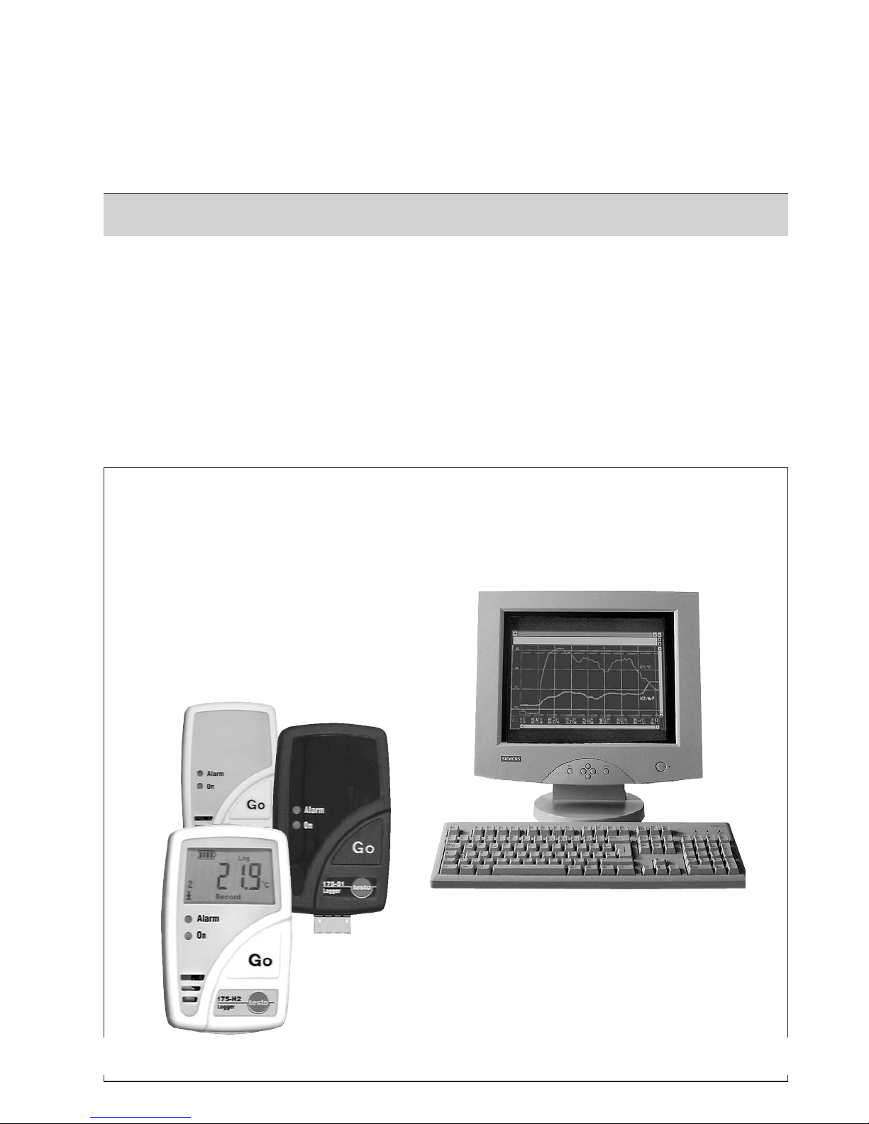
testo 175
1.888.475.5235info@Testo-Direct.com
www.Testo-Direct.com
Page 2

CCooppyyrriigghhtt
2
All rights reserved.
No part of this publication may be reproduced, stored in a retrieval
system, or transmitted, in any form or by any means, electronic,
mechanical, photocopying, recording, or otherwise, without the
prior permission of Testo AG.
We reserve the right to modify the technical data contained in the
descriptions, data and graphics in this documentation.
Testo AG
Postfach 11 40
79849 Lenzkirch
Germany
Microsoft®, Windows®, Excel® and Internet Explorer® are
registered trademarks of the Microsoft Corporation.
1.888.475.5235info@Testo-Direct.com
www.Testo-Direct.com
Page 3
Introduction
Dear Customer
Thank you for purchasing a Testo product. We hope you will enjoy the benefits of this product for a long
time to come and that it will help you with your work.
Please take the time to read the instruction manual carefully and make sure you become familiar with
how the instrument operates before using it.
If there are any problems, which you cannot solve yourself, please contact our Customer Service
Department or your nearest distributor. We will do our best to help you quickly and competently to
reduce downtimes.
General iinformation
Warnings and particularly important information, which has to be observed when working with this
product, are highlighted in this instruction manual as follows
Warnings
Warnings are marked by a warning symbol. The appropriate
Warning ttitle
indicates the danger level:
Warning!
means death or serious physical injury may occur if the specified safety measures
are not carried out.
Caution!
means minor physical injury or damage to property may occur if the specifed
safety measures are not carried out.
Read all the warnings carefully and carry out the specified safety measures to avoid
danger.
Important iinformation
Particularly important information is highlighted in this instruction manual by an exclamation mark.
Standards
The conformity certificate confirms that this product fulfills the guidelines in accordance with
2004/108/EEC
.
IInnttrroodduuccttiioonn // GGeenneerraall iinnffoorrmmaattiioonn
3
WWaarrnniinngg ttiittllee!!
1.888.475.5235info@Testo-Direct.com
www.Testo-Direct.com
Page 4

CCoonntteennttss
4
Copyright ..........................................................2
Introduction / General information ......................3
Contents............................................................4
1. Basic safety instructions ....................................6
2. Intended use......................................................7
3. Initial operation ..................................................8
4. Display and control elements ............................9
4.1 Display ........................................................................9
4.2 LED functions ............................................................10
4.3 Display sequence ......................................................10
4.4 Button functions ........................................................11
5. Mounting ........................................................12
5.1 Mounting the wall holder ............................................12
5.2 Securing the data logger with lock ............................12
5.3 Transportable unit ......................................................12
6. Connecting probes ..........................................13
7. Programming ..................................................14
7.1 Installing software ......................................................14
7.2 Connecting data logger to PC ....................................14
7.3 Setting up connection ................................................15
7.4 Opening the connection ............................................16
7.5 Programming the data logger ....................................17
7.6 Closing the connection ..............................................23
8. Reading out data ............................................24
9. Changing the battery ......................................25
10. Error messages................................................26
1.888.475.5235info@Testo-Direct.com
www.Testo-Direct.com
Page 5

CCoonntteennttss
11.Technical data ..................................................27
11.1 testo 175-T1 ..............................................................27
11.2 testo 175-T2 ..............................................................28
11.3 testo 175-T3 ..............................................................29
11.4 testo 175-S1, testo 175-S2 ......................................30
11.5 testo 175-H1 ..............................................................31
11.6 testo 175-H2 ..............................................................32
11.7 Battery life ..................................................................33
12. Accessories / Spare parts................................34
5
1.888.475.5235info@Testo-Direct.com
www.Testo-Direct.com
Page 6
6
Please read through the following safety instructions carefully:
Avoiding eelectricity:
Never use the instrument and external probes to measure on or near live parts if the instrument is not
expressly approved for current and voltage measurement!
Product ssafety:
Prior to each measurement, check if the connections are connected properly via the blind plug and if
the right probe is correctly inserted. Otherwise the protection class specified in the Technical data
cannot be guaranteed.
The logger should only be operated within the parameters specified in the Technical data.
Please handle the logger with care.
The instrument should only be opened if expressly described in the instruction manual for
maintenance purposes.
Force should never be applied!
Only for testo 175-T3
The probe sockets in testo 175-T3 are not isolated from one another. Please take note of this when
using surface probes with a non-insulate thermocouple.
Disposal:
Please dispose of spent batteries responsibly.
You can return your logger directly to us at the end of its service life. We will dispose of it responsibly.
11.. BBaassiicc ssaaffeettyy iinnssttrruuccttiioonnss
1.888.475.5235info@Testo-Direct.com
www.Testo-Direct.com
Page 7

22.. IInntteennddeedd uussee
7
The testo 175 data loggers are used to save and read out separate readings and measurement
sequences. The readings are measured, saved and transmitted to a PC, to the testo 575 fast printer or to
the testo 580 data collector per infrared using testo ComSoft software.
Applications
testo 175 - T1
User-friendly and affordable
temperature monitoring
during transport, in refrigerated rooms, in
display cabinets, in containers, when
monitoring rooms
Fulfills guidelines in accordance with
EN 12830 standards *
testo 175 - T2
Simultaneous product and air temperature
monitoring
during transport, in refrigerated rooms, in
containers, during production
Fulfills guidelines in accordance with
EN 12830 standards *
testo 175 - T3
Simultaneous product and air temperature
monitoring
in technical laboratories, during production,
in the domestic building sector, during metal
processing
testo 175 - S1 / S2
Easy checks on current and voltage circuits
in industrial processes, in laboratories, in
control systems, during development, in
production, when logging transmitter signals
See
6. CConnecting pprobes
, P. 13!
testo 175 - H1
Reliable monitoring of humidity and
temperature values
during industrial processes, in laboratories,
in museums, in warehouses, for domestic
building sector
testo 175 - H2
Reliable monitoring of humidity and
temperature values
during industrial processes, in laboratories,
in museums, in warehouses, in domestic
building sector
* In accordance with EN 12830, please ensure that a regular check and calibration in accordance with
EN 13486 (recommendation: once a year) is carried out on this instrument. Please contact us for
more detailed information.
Only for testo 175 - T1 and testo 175 - T2
The following components of the product are designed for continuous contact with
foodstuffs in accordance with the regulation
(EG) 1935/2004:
The measurement probe up to 1 cm before the probe handle or the plastic housing. If
provided, the information about penetration depths in the instruction manual or the mark(s)
on the measurement probes should be noted.
1.888.475.5235info@Testo-Direct.com
www.Testo-Direct.com
Page 8
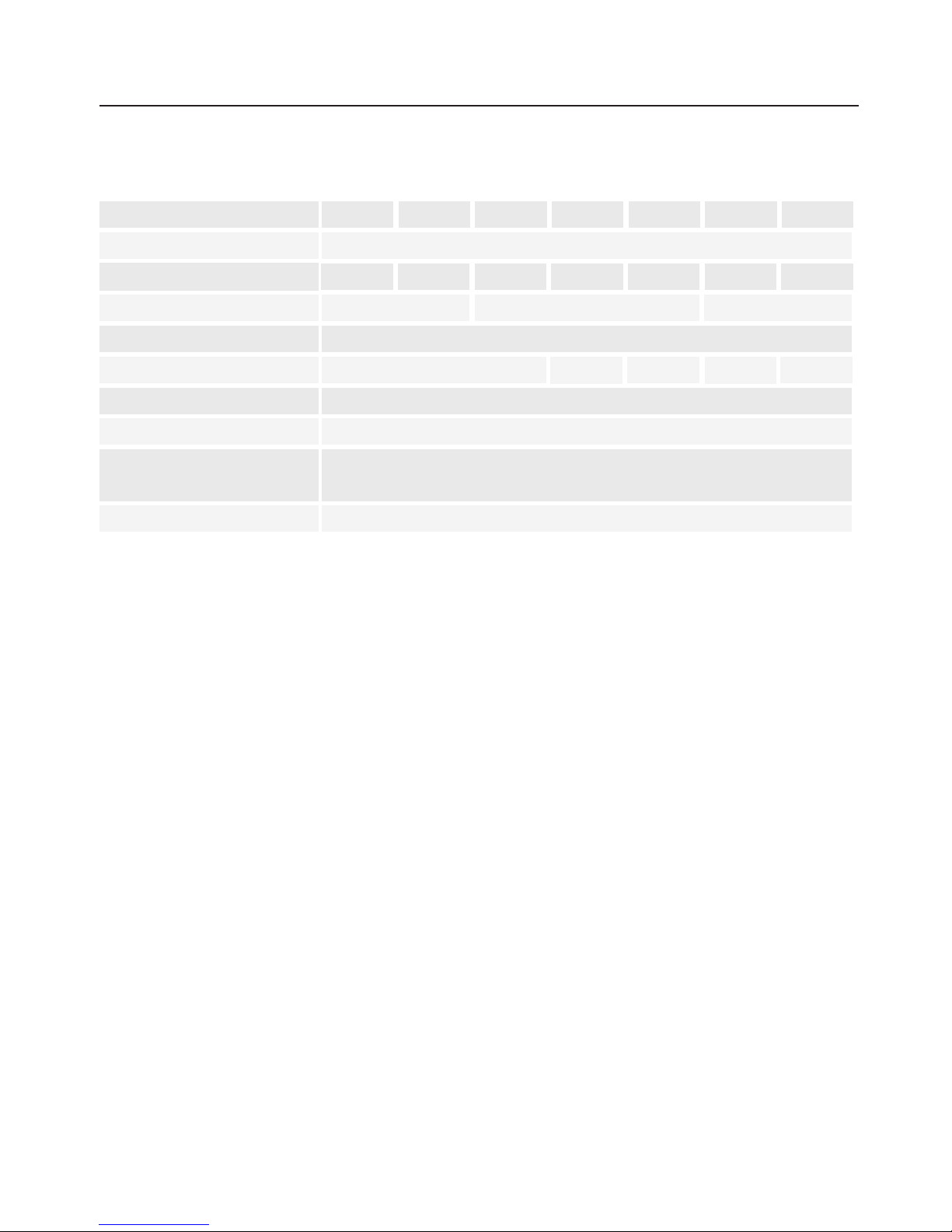
The data loggers have the defaults below:
* testo 175-T3: T/C -Type “K” programmed
testo 175-S1: “0 to 10V” programmed
testo 175-S2: “0 to 10V” programmed
The data logger with the above factory defaults can be used
immediately.
If you wish to use other measurement criteria, you will have to
program your data logger in accordance with your requirements
using testo ComSoft software (See
7. Programming
, P. 14).
External probes can be attached to many of the data loggers (See
6. CConnecting pprobes
, S. 13).
33.. IInniittiiaall ooppeerraattiioonn
8
Type
175-T1 175-T2 175-T3 175-S1 175-S2 175-H1 175-H2
Start ccriterion
Key start
Measuring rrate
5 min. 5 min. 10 s 1 s 1 s. 1 min. 1 min.
Stop ccriterion
Wraparound memory Until memory is full Wraparound memory
Alarm vvalues
Respective measuring range full-scale values (See Technical data)
Display
On - On - On
LEDs
Status led (green): Off / Alarm led (red): On
Measurement cchannels
All channels switched on*
Fast pprinter //
Stop: Switched on
data ccollector ffunction
New programming: Switched on
Protocol nname
testo175-{Type}_{Serial number}
1.888.475.5235info@Testo-Direct.com
www.Testo-Direct.com
Page 9
44.. DDiissppllaayy aanndd ccoonnttrrooll eelleemmeennttss
9
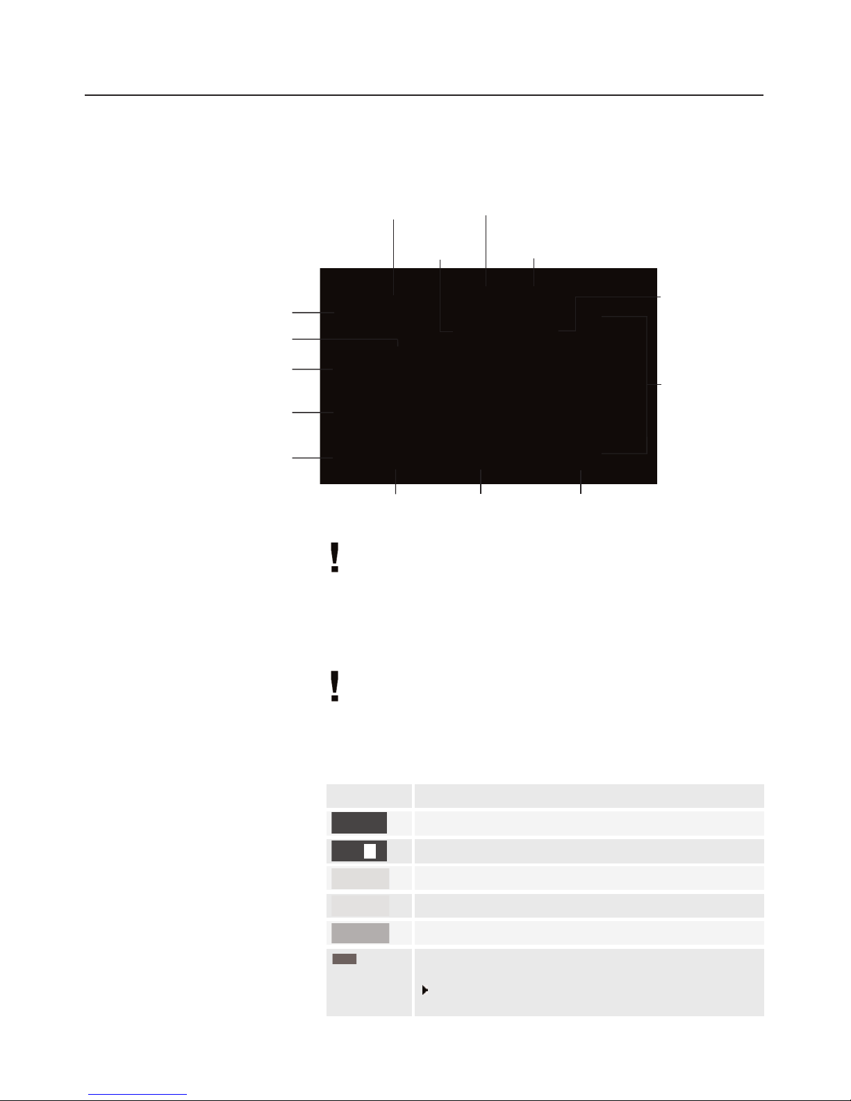
4.1 DDisplay
The display function can be activated/deactivated via the testo
ComSoft
software. The testo 175-S1 and testo 175-H1 data
loggers do not have a display.
testo 175-T1, testo 175-T2, testo 175-T3, testo 175-H2
and testo 175-S2
:
1
Intermediate readings are shown in the display but are not saved.
Due to technical reasons, the display speed of the liquid crystals
slows down at temperatures below 0 °C
(approx. 2 s at -10 °C, approx. 6 s at -20 °C). However, this
does not have any influence on the accuracy of the
measurement.
Battery ccapacity
22
Bottom alarm value
Waiting on measuring
program to start
Measuring program
is running
Measuring
program finished
Top alarm value
Battery
capacity
Readings
Saved reading
Intermediate
reading
1
Highest
reading
Lowest
reading
Channel 1
Units
Channel 2
Symbol
33
OFF
Capacity
75-100%
50-75%
25-50%
10-25%
<10%
Battery empty (measuring program was stopped)
Reading out data and changing battery (See
9. Changing bbattery
, P. 25)
2
Reference values (See
1111..77 BBaatttteerryy
lliiffee
, P. 33)
3
The battery symbol is updated when:
- the wraparound memory is full
- measurement program is
started/ended
- In
Record
mode:
Once a day
- the
GO
button is pressed:
if last measurement was more than
24 hours ago
The following units are shown in
the
175 - SS2
data logger display:
mV, %, °F, °C and mA.
No unit appears in the display if
other units are selected in
ComSoft. The selected unit is
displayed in the readings if the
saved data is imported to
ComSoft.
1.888.475.5235info@Testo-Direct.com
www.Testo-Direct.com
Page 10
44.. DDiissppllaayy aanndd ccoonnttrrooll eelleemmeennttss
10
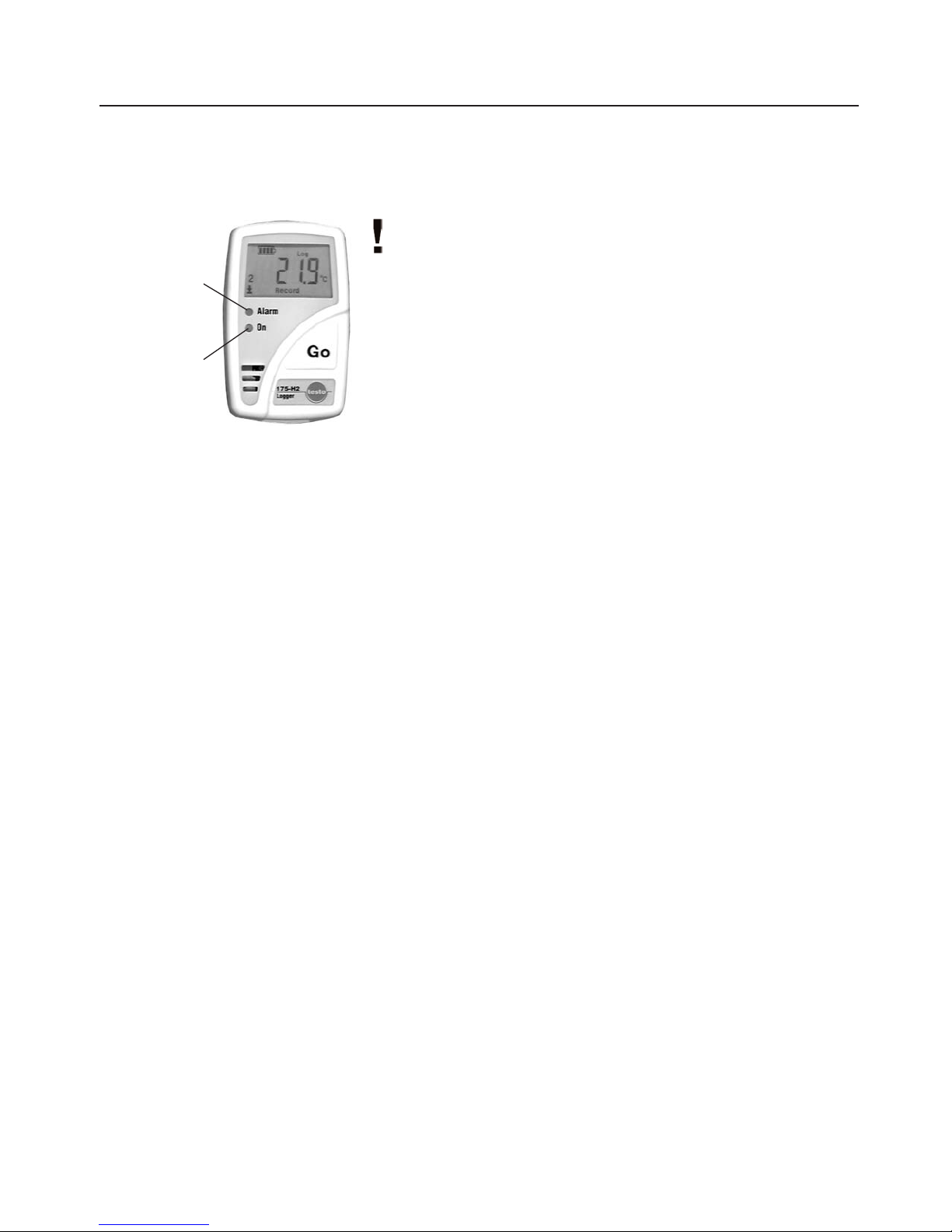
4.2 LLED ffunctions
The LED functions can be switched on/off via
testo ComSoft software.
In aall mmodes:
The Alarm led flashes three times every 15 seconds if the remaining
battery capacity is less than10% (even if Alarm led is deactivated).
Wait
mode aand
Key sstart
start ccriterion pprogrammed:
The status led flashes five times if the GObutton is kept pressed
for approx. 3 s (even if the Status led is deactivated).
It is confirmation that the measuring program was started and that
the data logger is now in the
Record
mode.
Record
mode:
The Alarm led flashes once every 15 s if alarm values have been
exceeded (only if Alarm led is activated).
The Status led flashes once every 15 s (only if the Status led is
activated).
It is confirmation that the measuring program is running.
The Status led flashes five times if the GObutton is kept pressed
for approx. 3 s (even if Status led is deactivated).
It is confirmation that a time mark has been set.
4.3 DDisplay ssequence
Depending on the mode, different information can be displayed in
the data loggers with display. You will find a detailed description of
the information which can be called up in the short version of the
instruction manual enclosed with every data logger.
Alarm led
(red LED)
Status led
(green LED)
1.888.475.5235info@Testo-Direct.com
www.Testo-Direct.com
Page 11
44.. DDiissppllaayy aanndd ccoonnttrrooll eelleemmeennttss
11
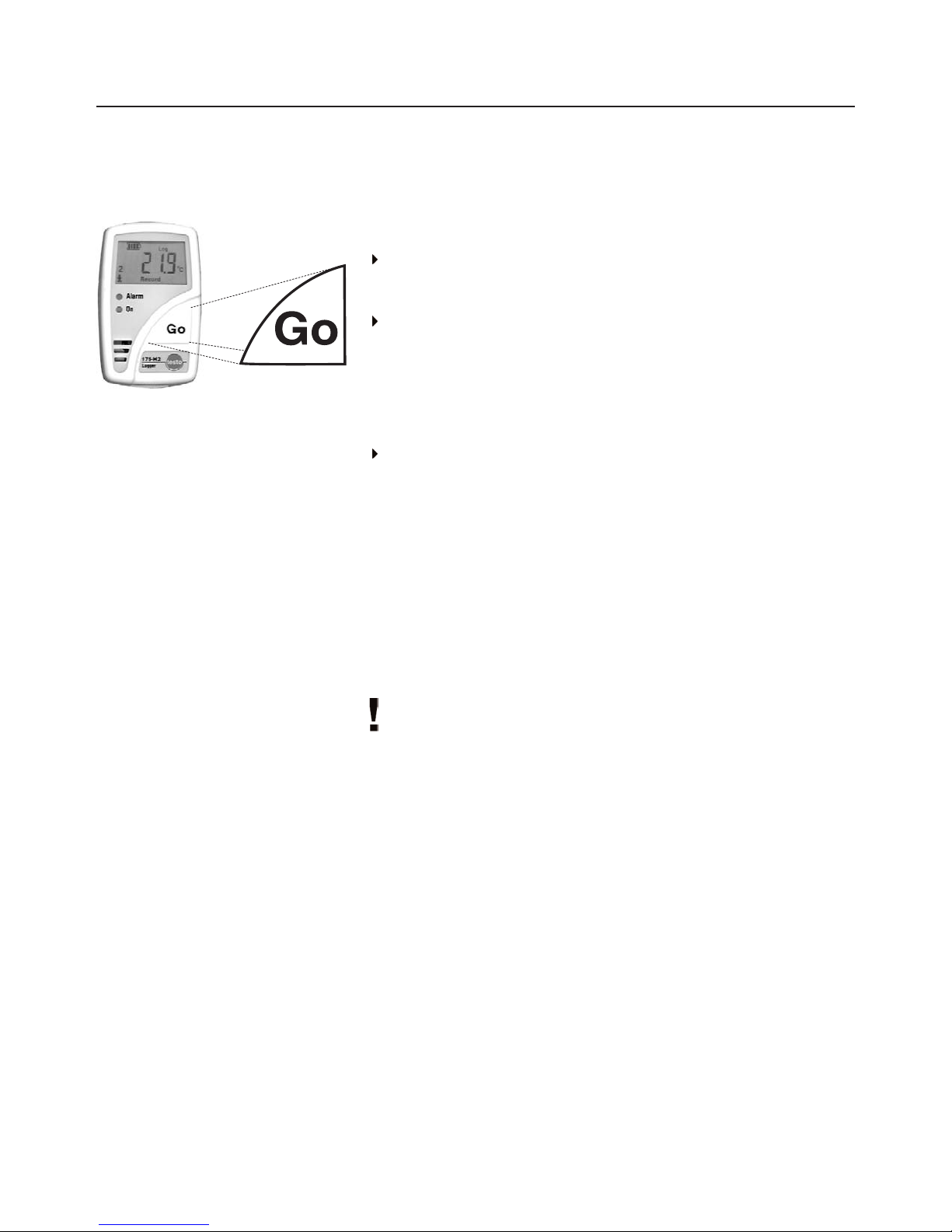
4.4 BButton ffunctions
In aall mmodes iin ddata lloggers wwith ddisplay:
Press the GObutton to switch between the displays.
Wait
mode aand
Key sstart
start ccriterion pprogrammed:
Press the GObutton for approx. 3 s to start the measuring
program.
- The measuring program starts,
Record
appears in the display (if
available) and the Status led flashes five times.
Record
mode:
Press the GObutton for approx. 3 s to set a time mark.
- The Status led flashes five times.
Time mmark:
This function enables you to monitor and read out/print
out the memory content from a specified point in time (
time mark
)
without having to reprogram the data logger. The readings from
Start(All readings
) are also saved.
The readings from
Start(All readings
) or
From time mark
can be
read out on the testo 575 fast printer or the testo ComSoft software.
The readings from
Start(All readings
) can be read out on the
testo 580 data collector.
Only one time mark can be set. If the GObutton is pressed for
approx. 3 seconds in the
Record
mode, the existing time mark
is deleted and a new time mark is set up.
- The readings (max./min. values, exceeding of alarm values) are
shown in the display (if available) from the set time mark.
1.888.475.5235info@Testo-Direct.com
www.Testo-Direct.com
Page 12
55.. MMoouunnttiinngg
12
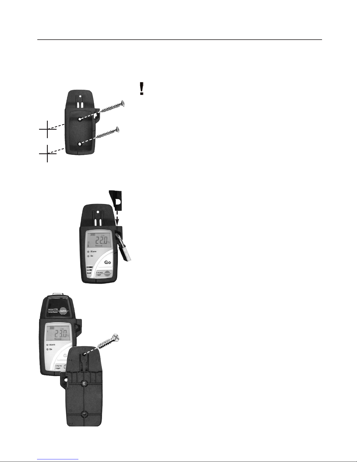
5.1 MMounting tthe wwall hholder
Mounting materials (e.g. screws, dowels) are not included.
1
Position the wall holder at the required location.
2
Using a pencil or similar, mark where the fixing screw is to go.
3
Prepare the area for mounting (e.g. drill a hole, put in dowel).
4
Mount the wall holder using a screw which fits.
5.2 SSecuring tthe ddata llogger wwith aa llock
1
Insert the data logger into the wall holder.
2
Place the retainer key in the wall holder.
3
Attach the lock to the wall holder (Accessory: Part no.
0554 1755).
5.3 TTransportable uunit
A unit can be made out of the wall holder, logger and the interface
to make transport or dispatch easier.
1
Push the data logger into the wall holder.
2
Push the interface onto the wall holder.
3
Secure the unit by connecting the wall holder and the interface
using the screw supplied.
1.888.475.5235info@Testo-Direct.com
www.Testo-Direct.com
Page 13

66.. CCoonnnneeccttiinngg pprroobbeess
13
Observe the following points when connecting the probes to the
data logger and to the measurement points:
Observe poles of plug.
Insert the plugs firmly into the connections to guarantee that
they are properly in place. Force should not be used.
Ensure that the plugs are firmly attached to the data logger or
that the connections are in place with a blind plug.
Ensure that the probe is positioned properly to avoid disturbing
influences on the measurement.
testo 175-T3
:
Ensure that each respective configured probe is connected to
the socket (via testo ComSoft software). The numbers of the
connections are printed on the housing!
testo 175-S1/S2
:
The testo 175-S1/S2 data logger is designed for use in electric
circuits in measurement technology, automatic control, information
technology in process, laboratory and technical systems (0 to
20mA current loop; 0-1V, 0-10V voltage sockets).
Connect the cables by following the printed connection plan.
Warning!
Strong currents and high voltage!
Electric sshock!
The
testo 175-S1 and testo 175-S2 data logger should only be connected to electric
circuits from the SELV (safety extra-low voltage) or PELV (protective extra-low voltage)
category.
The testo 175-S1 and testo 175-S2 data logger should only be connected to direct
current circuits.Rated voltage should only be max. 60 V DC.
The electric circuits in the data logger should only be set up, connected, operated
and maintained by trained personnel.
Disconnect the measurement leads from the logger before changing the battery.
1.888.475.5235info@Testo-Direct.com
www.Testo-Direct.com
Page 14

14
77.. PPrrooggrraammmmiinngg
7.1 IInstalling ssoftware
In order to program your data logger in accordance with your
individual needs, you will need a PC on which the testo ComSoft
software is installed.
You will find instructions on the installation and operation of the
software in the testo ComSoft instruction manual.
Continue with
7.2 Connecting ddata llogger tto PPC
, P. 14 once the
software is successfully installed.
7.2 CConnecting ddata llogger tto PPC
You will need a free serial interface (RS232) or a USB interface to
connect the data logger interface to your PC.
1
Connect the serial connection cable or USB connection cable
of the interface to your PC.
2
Connect the interface to the connection cable.
3
Insert the interface in the desk-top holder.
4
Place the logger in the desk-top holder.
The interface can be placed directly in the wall holder. In this
way, the data can be read out directly on location.
Ensure that the interface is completely plugged on and snapped
into place. Otherwise the connection is not guaranteed.
5
Start the testo ComSoft software.
1.888.475.5235info@Testo-Direct.com
www.Testo-Direct.com
Page 15

15
77.. PPrrooggrraammmmiinngg
7.3 SSetting uup tthe cconnection
1
Start testo ComSoft software.
testo CComsoft 44:
2
Select
IStart > New device
.
- The
New device setup wizard
opens.
testo CComsoft 33:
2
Select
Instrument > Autodetect...
.
-
Autodetect
opens.
- The connection to the data logger found is set up automatically
and the name of the connection appears in the
Data
window.
-oor-
2
Select
Instrument > New device
- The
New device setup wizard
opens.
3
Select
testo175-177
in Device selection and click on
Next
.
4
Select the interface in
Connection
, with which you have
connected your data logger to your PC and click on
Next
.
5
Enter a name for the connection and click on
Finish
.
1.888.475.5235info@Testo-Direct.com
www.Testo-Direct.com
Page 16

16
77.. PPrrooggrraammmmiinngg
Confirmation oof bbattery cchange
- If the data logger is used for the first time or the data logger
battery has been changed, the
New battery
window opens.
Enter the date when the battery was changed.
Enter the temperature range in which you will use the data
logger and confirm with OK.
- The connection to the data logger is set up. The name of the
connection appears in the
Data
window.
7.4 OOpening tthe cconnection
Click twice on the connection, which you want to open, in the
Data
window.
- If a protocol is saved in the data logger, the protocol symbol and
the title appear under the opened connection.
The readings saved in the data logger are not transmitted to the
PC when the connection is opened. Carry out the following to
transmit the readings:
Click twice on the title of the protocol (See testo ComSoft
software instruction manual).
Use oone cconnection ffor sseveral ddata lloggers
You can connect different data loggers once a connection has
been set up. The connection must be closed when changing the
data logger and then opened again for the new data logger.
Otherwise, it cannot be identified by the software (See
7.6
Closing tthe cconnection
, P.23).
1.888.475.5235info@Testo-Direct.com
www.Testo-Direct.com
Page 17

17
77.. PPrrooggrraammmmiinngg
7.5 PProgramming tthe ddata llogger
Any readings in the data logger are deleted if the data logger is
programmed.
Read out any data from the data logger which may exist
before programming
(See testo ComSoft software instruction manual).
Select
Start
(Comsoft 4) or
Instrument
(Comsoft 3) >
Device
control
.
This function is only activated if the name of the connection is
highlighted. If this is not the case:
First click on the name of the connection so that it is highlighted
and then select
Start
(Comsoft 4) or
Instrument
(Comsoft 3) >
Device control
.
- The window for programming the data logger opens.
Window sselection
You will find a bar on on the left side in which the available windows
are shown. Click to select.
Programming rrecommendation
It is recommended to carry out programming first in the
Probes
and
Settings
windows and then in the
Program window
.
1.888.475.5235info@Testo-Direct.com
www.Testo-Direct.com
Page 18

18
77.. PPrrooggrraammmmiinngg
Instrument
You can read general information on the data logger in the
Instrument
window.
This window is a pure information window. Programming is not
possible.
Protocol
You can read information from the protocol currently stored in the
data logger in the
Protocol
window. You can choose to display
All
values
and
Since time mark
.
This window is an information window. Programming is not
possible.
1.888.475.5235info@Testo-Direct.com
www.Testo-Direct.com
Page 19

19
77.. PPrrooggrraammmmiinngg
Probes
Probes:
Activate the probes available or deactivate them.
Unit:
Displays the set unit for the respective channel.
You cannot change the unit in this window, but in the
Settings
,
window.
LL:
The lower alarm limit for the channels is entered here.
UL:
The upper alarm limit for the channels is entered here.
Name:
Enter a name for the channel here.
1.888.475.5235info@Testo-Direct.com
www.Testo-Direct.com
Page 20

20
77.. PPrrooggrraammmmiinngg
Settings
Date and time:
The set date and the time in the data logger are shown.
Select
Synchronize
to synchronize the date and the time in the
data logger with the clock in your PC.
Date/Time can only be synchronized when the data logger is in
the
Wait
or
End
mode.
Temperature:
Select the required temperature unit for the temperature
channels (°Cor °F).
testo 575/ testo 580
- Function:
Select whether the data logger is to be newly programmed (
New
programming
) and stopped (
Stop
) via the testo 575 fast printer
and the testo 580 data collector.
Display functions:
Select whether the LEDs, the
Alert led
, Status led and
Display
on are to be activated in the data logger.
Only the data display is deactivated when the display is
switched off. Status information on mode and battery capacity
are always shown.
Enable limit signal output
From ComSoft Version 3.4 on, the external alarm signal output
testo 581 can be activated if connected to a data logger.
1.888.475.5235info@Testo-Direct.com
www.Testo-Direct.com
Page 21

21
77.. PPrrooggrraammmmiinngg
Program
Start criterion:
Select the required criterion for the start of the program.
You have the choice between
Date/Time, Key start
and
PC Start
.
If
Date/Time
is chosen, an additonal field appears in which you can
enter/select the required date/time.
Measuring rate:
Select the time cycle in which the measurements are to be
carried out.
You can choose between sec (seconds),
min
(minutes), h(hours)
and d(days).
The smallest/largest measuring rate differs depending on the
instrument type (Refer to
11. TTechnical ddata
, P. 27).
Stop criterion:
Select the required criterion to stop the measuring program.
You can choose between
Until memory is full, No. of logs
,
Wraparound memory
and
Date / Time.
It is only possible to select
Date/Time
if
Date/Time
is also
selected as
Start criterion
. If you choose
No. of logs
an
additional field will appear in which the number of
measurements required can be entered.
1.888.475.5235info@Testo-Direct.com
www.Testo-Direct.com
Page 22

22
77.. PPrrooggrraammmmiinngg
Duration:
Indicates running time of program calculated on the basis of the
values for
Start criterion, Measuring rate
and
Stop criterion
.
If the
Wraparound
stop criterion is selected, the length of time until
the memory is full is calculated.
Estimated battery life:
Indicates estimated battery life.
Title:
Enter a Title for the measuring program.
Maximum 24 characters can be entered.
The title of the measuring program is accepted into the testo
ComSoft
software when the data logger is read out. The title will
appear at the top of the printout when the protocol is printed on
the testo 575 printer.
Comments:
Additional information on the measuring program can be entered
here.
The entered text is printed on the testo 575 printer printout. Up to
96 characters can be entered. The fast printer automatically enters
return after every 24 characters.
Send to:
Activate the function by clicking on the selection window and
enter an e-mail address in the text box.
Once the measurement protocol has been opened in the testo
ComSoft
software, you can send it by e-mail via
testo-Logo
>
Senden
(Comsoft 4) or
File > Send ... by emai
. (Comsoft 3). The
entered email address and the log are automatically saved in your
e-mail.
System requirement for this function:
Microsoft Windows 95 or newer and
Microsoft Internet Explorer 5.0 or newer.
Start and Stop:
Click on
Start
to start a measuring program..
This function can only be selected if
PC start
has been selected as
Start criterion
.
Click on
Stop
to end a measuring program.
This function can only be selected if a measurement is running.
1.888.475.5235info@Testo-Direct.com
www.Testo-Direct.com
Page 23

23
77.. PPrrooggrraammmmiinngg
Programming eended
Click on
Apply
to transmit the programming to the data logger.
A measuring program can only apply in the data logger if it is in
the
Wait
or
End
mode.
If a measurement is running (
Record
mode):
Finish the measurement by clicking on
Stop.
- The
Programming data
window opens to confirm the following
programming.
7.6 CClosing tthe cconnection
1
Click on the connection you wish to close with your right mouse
button in the
Data
window.
2
Select
Close
.
- The connection to the data logger is closed.
1.888.475.5235info@Testo-Direct.com
www.Testo-Direct.com
Page 24

24
88.. RReeaaddiinngg oouutt ddaattaa
You have three options to read out data from the data logger:
1.
Via testo ComSoft software. Data is transmitted directly to a
PC.
Please read the Instruction manual on the testo ComSoft
software.
testo ComSoft software is available in 2 versions with the following
range of functions:
testo ComSoft 3 Basic
- Programming and reading out the testo 174,
testo 175 and testo 177 data loggers
- Display and printout as table or diagram
- Data export (e.g. in Microsoft Excel)
testo ComSoft 3 Professional
(0554.0830)
like testo ComSoft 4 Basic, but with the following additional features:
- Programming and reading out other Testo instruments such
as testo 400, testo 650, etc.
- Display and printout as number box, histogram, form, analog
instrument, parametric graph
- Data management function
- Analysis functions (compensation curve, mean function)
- Selection of different printing heads for table and graph
printouts
- Adaptation of menus and range of functions
- Developer ToolBox with functions to incorporate the instrument
driver in non-Testo software
2.
Via the testo 580 data collector.
Data can then be read out via testo Comsoft software.
For more information, refer to the testo 580 Instruction
manual.
3.
Printout via testo 575 fast printer
For more information, refer to the testo 575 Instruction
manual.
1.888.475.5235info@Testo-Direct.com
www.Testo-Direct.com
Page 25

25
99.. CChhaannggiinngg tthhee bbaatttteerryy
1
Please read out the saved data before changing the battery. See
testo ComSoft software Instruction manual
If it is not possible to read out the saved data due to low battery
capacity, please carry out the following:
First change the battery and then read out the saved data
(no data will be lost).
2
Remove the screw at the back of the data logger using a small
crosstip screwdriver.
3
Using a screwdriver, lift the back wall at the bottom of the data
logger and then remove from data logger 1.
4
Attach the jumper (included with spare battery) to the plug
connector beside the connection for the battery 2.
The inserted jumper prevents the memory from being deleted or
written over.
5
Take the battery out of the battery compartment and pull out the
plug-in connection to the data logger 3.
6
Connect the new battery to the data logger`s plug-in connection
and place in battery compartment.
Only original Testo spare batteries should be used
(see
12. AAccessories/Spare pparts
, P. 34 for Part nos).
7
Remove the jumper from the plug connector.
8
Hold the back wall at a 45° angle to the top of the instrument
and then flip down.
Ensure that both O rings are positioned on the screw so as to
guarantee that it is sealed completely.
9
Press the back wall onto the logger with your thumbs. Make
sure that it is closed properly 4 and then secure using screw.
10
Place the data logger in the desk-top holder and attach to
interface.
11
Start the testo ComSoft software and set up a connection to the
data logger by clicking twice on the required connection with the
left mouse button.
- The
New battery
window is opened 5.
Enter the date of battery change.
Enter the temperature range in which you will be using the
data logger and confirm with OK.
- The data logger is now ready for use.
1
2
3
4
5
1.888.475.5235info@Testo-Direct.com
www.Testo-Direct.com
Page 26

26
1100.. EErrrroorr mmeessssaaggeess
If problems occur which are not described here, please contact Testo or your local distributor. For
contact data, see back of this document or web page www.testo.com/service-contact
Possible ccauses
Battery power too low
Battery empty
Measuring program was
cancelled by Reset
An attempt was made to
start the data logger via
GO
: data logger indicates
that
Start criterion PC Start
is programmed.
An attempt was made to
start the data logger via
GO
: data logger indicates
that
Start criterion
Date/Time Start
is
programmed.
The GObutton was
pressed for more than 3
seconds in the
END
mode
Remedy // CComments
Read out data and change battery
(See
9. Changing bbattery
, P. 25)
Communication with PC is possible. Communi-
cation with testo 575 fast printer/ testo 580 data
collector is not possible.
Change battery (See
9. Changing
battery
, P. 25)
No communication with PC / testo 575 fast
printer/ testo 580 data collector possible.
Reactivate data logger via testo ComSoft
software
Start the data logger via PC
or change the
Start criterion
to
Key start
.
Change
Start criterion
to
Key start
.
No function is allocated.
Error mmessage
OFF
and
END
are lit,
flashes
OFF
is lit
OFF, END
and
are lit
PC
is lit
date
is lit
Red and green LEDs
flash alternately five
times
1.888.475.5235info@Testo-Direct.com
www.Testo-Direct.com
Page 27

27
1111.. TTeecchhnniiccaall ddaattaa
11.1 ttesto 1175-TT1
Parameter
..........................................................Temperature (°C/°F)
Sensor
..........................................................................NTC internal
Number oof mmeasuring cchannels
......................................1 x internal
Measuring rrange
........................................................-35 to +70 °C
Accuracy
....................................................± 0.5 °C (-20 to +70 °C)
....................................................................± 1 °C (-35 to -20.1 °C)
............................................................................................±1 digit
Resolution
......................................................0.1 °C (-20 to +70 °C)
................................................................0.3 °C in remaining range
Measuring rrate
..................................10 s to 24 h (freely selectable)
Adaptation ttime tt
9900
(internal)
............Approx. 30 min. at wind speed 1m/s
Storage ttemperature
..................................................-40 to +85 °C
Operating ttemperature
................................................-35 to +70 °C
Operating ttemperature/Display
..................................-30 to +65 °C
Memory ccapacity
......................................................7,800 readings
Protection cclass
........................................................................IP 68
Housing
............................................................................ABS/TPE
Dimensions iin mmm ((lxwxh)
..........................................82 x 52 x 30
Weight
........................................................................................90g
Battery
........................................................................Lithium (1 AA)
Battery llife
............................................................Typical: 2½ years*
......(Measuring rate: 15 Min., Operating temperature: -10 to +50°C,
..........................................Display: On, Status led (green LED): Off)
* See Chapter
11.7 BBattery llife
, P. 33
1.888.475.5235info@Testo-Direct.com
www.Testo-Direct.com
Page 28

28
1111.. TTeecchhnniiccaall ddaattaa
11.2 ttesto 1175-TT2
Parameter
..........................................................Temperature (°C/°F)
Sensor
..............................................................NTC (intern+extern)
Number oof mmeasuring cchannels
................2 (1x internal/1x external)
Measuring rrange
............................................-35 to +70 °C internal
....................................................................-40 to +120 °C external
Accuracy, iinternal
......................................± 0.5 °C (-20 to +70 °C)
(System)
......................................................± 1 °C (-35 to -20.1 °C)
............................................................................................±1 digit
Accuracy, eexternal
......................................± 0.3 °C (-25 to +70 °C)
(only LLogger)
....................................± 0.5 °C in the remaining range
............................................................................................±1 digit
Resolution
......................................................0.1 °C (-20 to +70 °C)
................................................................0.3 °C in remaining range
Measuring rrate
..................................10 s to 24 h (freely selectable)
Adaptation ttime tt
9900
(internal)
....Approx. 30 min at wind speed 1m/s
Storage ttemperature
..................................................-40 to +85 °C
Operating ttemperature
................................................-35 to +70 °C
Operating ttemperature/Display
..................................-30 to +65 °C
Memory ccapacity
....................................................16,000 readings
Protection cclass
........................................................................IP 68
Housing
............................................................................ABS/TPE
Dimensions iin mmm ((lxwxh)
..........................................82 x 52 x 30
Weight
........................................................................................84g
Battery
........................................................................Lithium (1 AA)
Battery llife
............................................................Typical: 2½ years*
......(Measuring rate: 15 min., Operating temperature: -10 to +50°C,
..........................................Display: On, Status led (green LED): Off)
* See Chapter
11.7 BBattery llife
, P. 33
1.888.475.5235info@Testo-Direct.com
www.Testo-Direct.com
Page 29

29
1111.. TTeecchhnniiccaall ddaattaa
11.3 ttesto 1175-TT3
Parameter
..........................................................Temperature (°C/°F)
Sensor
......................................................T/C-Type K or T (external)
Number oof mmeasuring cchannels
..................................2 (2x external)
Measuring rrange
......................................-50 to +1000 °C (Type K)
....................................................................-50 to +400 °C (Type T)
Accuracy/Logger
........................................±0.5 °C (-50 to +70 °C)
............................................±0.7% of reading (+70.1 to +1000 °C)
............................................................................................±1 digit
Resolution
..............................................................................0.1 °C
Measuring rrate
..................................10 s to 24 h (freely selectable)
Storage ttemperature
..................................................-40 to +85 °C
Operating ttemperature
..................................................0 to +70 °C
Operating ttemperature/Display
......................................0 to +65 °C
Memory ccapacity
....................................................16,000 readings
Protection cclass
........................................................................IP 54
Housing
............................................................................ABS/TPE
Dimensions iin mmm ((lxwxh)
..........................................82 x 52 x 30
Weight
........................................................................................90g
Battery
....................................................................Lithium (1/2 AA)
Battery llife
............................................................Typical: 2½ years*
........(Measuring rate: 15 Min., Operating temperature: 0 to +50°C,
..........................................Display: On, Status led (green LED): Off)
* See Chapter
11.7 BBattery llife
, P. 33
1.888.475.5235info@Testo-Direct.com
www.Testo-Direct.com
Page 30

30
1111.. TTeecchhnniiccaall ddaattaa
11.4 ttesto 1175-SS1; ttesto 1175-SS2
Parameters
................................................Current (mA) / Voltage (V)
Sensor
............................................Built-in screwed contact socket
No. oof mmeasuring cchannels
..............................................1x external
Measuring rranges
................................................0 to 1V / 0 to 10V
..................................................................0 to 20 mA / 4 to 20 mA
Accuracy/System
................................................±2 mV (0 to 1 V) /
........................................................................± 20 mV (0 to 10 V) /
....................................................................±0.05 mA (0 to 20 mA)
............................................................................................±1 digit
Resistances
......................................................................................
10V input ........................................................................ca. 111 kΩ
1V input ............................................................................ca. 11 kΩ
20mA input ................................Measurement resistance ca. 250 Ω
Resolution
................................1 mV (0 to 1 V) / 10 mV (0 to 10 V) /
......................................................................0.01 mA (0 to 20 mA)
Measuring rrate
....................................1 s to 24 h (freely selectable)
Storage ttemperature
..................................................-40 to +70 °C
Operating ttemperature
................................................-10 to +50 °C
Memory ccapacity
....................................................16,000 readings
Housing
............................................................................ABS/TPE
Dimensions iin mmm ((lxwxh)
..........................................82 x 52 x 30
Weight
........................................................................................80g
Battery
....................................................................Lithium (1/2 AA)
Battery llife
............................................................Typical: 2½ years*
......(Measuring rate: 15 min., Operating temperature: -10 to +50°C,
..........................................Display: On, Status led (green LED): Off)
* See Chapter
11.7 BBattery llife
, P. 33
1.888.475.5235info@Testo-Direct.com
www.Testo-Direct.com
Page 31

31
1111.. TTeecchhnniiccaall ddaattaa
11.5 ttesto 1175-HH1
Parameters
............................Humidity (%RH) / Temperature (°C/°F)
Sensor
..........................................................Humidity sensor / NTC
Number oof mmeasuring cchannels
........................................2x internal
Measuring rrange
..........................0 to 100 %RH (no condensation)
..................................................................................-10 to +50 °C
Accuracy
..............................................................................±0.5 °C
..............................................±3 %RH at rated temperature +25°C
............................................................................................±1 digit
Resolution
..............................................................................0.1 °C
..........................................................................................0.1 %RH
Measuring rrate
..................................10 s to 24 h (freely selectable)
Storage ttemperature
..................................................-40 to +70 °C
Operating ttemperature
................................................-10 to +50 °C
Memory ccapacity
......................................................3,700 readings
Housing
............................................................................ABS/TPE
Dimensions iin mmm ((lxwxh)
..........................................82 x 52 x 30
Weight
........................................................................................80g
Battery
....................................................................Lithium (1/2 AA)
Battery llifetime
......................................................Typical: 2½ years*
......(Measuring rate: 15 min., Operating temperature: -10 to +50°C,
..........................................Display: On, Status led (green LED): Off)
* See Chapter
11.7 BBattery llife
, P. 33
1.888.475.5235info@Testo-Direct.com
www.Testo-Direct.com
Page 32

32
1111.. TTeecchhnniiccaall ddaattaa
11.6 ttesto 1175-HH2
Parameters
..............................Humidity (%rF) / Temperature (°C/°F)
Sensor
..........................................................Humidity sensor / NTC
Number oof mmeasuring cchannels
........................................2x internal
Measuring rrange
..........................0 to 100 %RH (no condensation)
..................................................................................-20 to +70 °C
Accuracy
..............................................................................±0.5 °C
..............................................±3 %RH at rated temperature +25°C
............................................................................................±1 digit
Resolution
..............................................................................0.1 °C
..........................................................................................0.1 %RH
Measuring rrate
..................................10 s to 24 h (freely selectable)
Storage ttemperature
..................................................-40 to +85 °C
Operating ttemperature
................................................-20 to +70 °C
Operating ttemperature/Display
..................................-20 to +65 °C
Memory ccapacity
....................................................16,000 readings
Housing
............................................................................ABS/TPE
Dimensions iin mmm ((lxwxh)
..........................................82 x 52 x 30
Weight
........................................................................................84g
Battery
....................................................................Lithium (1/2 AA)
Battery llife
............................................................Typical: 2½ years*
......(Measuring rate: 15 min., Operating temperature: -10 to +50°C,
..........................................Display: On, Status led (green LED): Off)
* See Chapter
11.7 BBattery llife
, P. 33
1.888.475.5235info@Testo-Direct.com
www.Testo-Direct.com
Page 33

33
1111.. TTeecchhnniiccaall ddaattaa
11.7 BBattery llife
Typical approximate values for the expected battery life are included
in the programming windows of the software. These values are
calculated on the basis of the following factors:
- Measuring rate
- Number of probes connected
- Status led (green LED) activated/deactivated
The calculated data is only an approximation since the battery life
depends on many additional factors.
The following factors have a negative influence on the battery life:
- Alarm LED flashing for longer periods of time
- Frequent reading out (several times a day)
- Strong fluctuations in operating temperature
The following factors have a positive influence on the battery life:
- Deactivated Status led (green LED) particularly in the case
of extended measuring rates
The battery capacity displayed is based on calculated values.
The data logger can be switched off if a critical power level has
been reached. The following could occur:
- The logger continues to take readings although the display
indicates that the battery capacity is “empty”.
- The measuring program is stopped even though the battery
capacity display indicated a short time previously that
battery capacity was available.
Saved readings are not lost if the battery is spent or
changed. Requirement:
The battery is changed by following the directions in the
Instruction manual.
1.888.475.5235info@Testo-Direct.com
www.Testo-Direct.com
Page 34

34
1122.. AAcccceessssoorriieess//SSppaarree ppaarrttss
Description Part nno.
testo 175-T1 (1channel temp. internal, display, wall holder, calibration protocol) 0563 1754
testo 175-T2 (2 channel temp. internal/external, display, wall holder, 0563 1755
calibration protocol)
testo 175-T3 (2 channel temp. external (for T/C), display, wall holder, 0563 1756
calibration protocol)
testo 175-H1 (2 channel/temp. internal, wall holder, calibration protocol) 0563 1757
testo 175-H2 (2 channel humidity/temp. internal, display, wall holder, 0563 1758
calibration protocol)
testo 175-S1 (1 channel current/voltage, built-in screwed contact socket, 0563 1759
wall holder, calibration protocol)
testo 175-S2 (1 channel current/voltage, display, built-in screwed contact socket, 0563 1761
wall holder, calibration protocol
testo 580 data collector incl. desk-top holder for testo 175/177 data loggers 0554 1778
testo 575 fast printer, infrared controlled thermal line printer with 0554 1775
graph function, incl. 1 roll of thermal paper and batteries
Thermal paper for printer (6 rolls) 0554 0569
Thermal paper for printer (6 rolls) for long-term legible data documentation 0554 0568
up to 10 years
Self-adhesive label thermal paper for printer (6 rolls) 0554 0561
Limit signal output 0554 1769
testo ComSoft 4 Basic Software Set for testo 175 incl. interface, desk-top holder and 0554 1759
PC connection cable RS232
testo ComSoft 4 Basic Software Set for testo 175 incl. interface, desk-top holder and 0554 1766
PC connection cable USB
testo ComSoft 3 Professional Software (without interface) 0554 0830
RS232 interface for testo 175/177 incl. desk-top holder and PC connection cable 0554 1757
USB interface for testo 175/177 incl. desk-top holder and PC connection cable 0554 1708
Ethernet adapter 0554 1711
Lock to secure testo 175/177 data logger in the wall holder 0554 1755
Retainer key to prevent testo 175/177 data logger from falling out of wall holder 0192 0638
Spare desk-top holder for testo 175 data logger 0554 1756
Spare wall holder for testo 175 data logger 0554 1754
Spare battery 1/2 AA (3.6V/0.8Ah) for testo 175-T3/H1/H2/S1/S2 0515 0175
Spare battery 1 AA (3.6V/1.9Ah) for testo 175-T1/T2 0515 0177
Transport case for up to 5 testo 175 data loggers and accessories 0516 1750
1.888.475.5235info@Testo-Direct.com
www.Testo-Direct.com
Page 35

1122.. AAcccceessssoorriieess//SSppaarree ppaarrttss
35
-35... +80 °C 0610 1725
Accurate immersion/penetration
probe,
cable length 6 m *
40 mm
Ø 3 mm
Ø 3 mm
-50... +70 °C 0613 4611
Pipe probe with Velcro, for pipe
diameter of max. 75 mm
300 mm
30 mm
-50... +150 °C 0613 1711
Robust, affordable air probe, for
checking storage temperature, for
example *
110 mm
Ø 4 mm
-50... +140 °C
0613 3211
Frozen food probe, no drilling
required *
110 mm
30 mm
Ø 4 mm
Ø 8 mm
-50... +150 °C 0613 2211
Food probe (IP65) made of stainless
steel, PUR cable, can be used up to
+80 °C, plug-in connection IP54 *
125 mm 15 mm
Ø 3 mm
Ø 4 mm
-50... +150 °C 0613 2411
Robust food penetration probe
with special handle, IP 65,
reinforced cable (PUR) and
reinforced bending protection *
115 mm
30 mm
Ø 3.5 mm
Ø 5 mm
-20... +90 °C 0628 7503
Mounting probe with aluminium
sleeve, IP65
Cable length: 2.40 m *
40 mm
Ø 6 mm
-50... +80 °C 0628 7514
Screw-in probe for measurements
in difficult to access places, M6
thread, IP 54; cable length: 2 m *
-50... +80 °C 0628 7516
Probe for surface measurement;
cable length: 2 m *
8 x 8 mm
-50... +80 °C 0628 7507
Wall surface temperature probe,
e.g. for proof of damage to building
structure; cable length: 3 m
-20... +70 °C
Stub probe *
MMeeaass.. rraannggeeDDeessccrriippttiioonn IIlllluussttrraattiioonn PPaarrtt nnoo..
40 mm
Accurate NTC probes for testo 175-T2 data loggers
* Probe tested in accordance with EN 12830 for suitability in the areas of transport and storage.
0628 7510
35 mm
Ø 3 mm
1.888.475.5235info@Testo-Direct.com
www.Testo-Direct.com
Page 36

1122.. AAcccceessssoorriieess//SSppaarree ppaarrttss
36
Accurate thermocouple probes for testo 175-T3 data loggers:
-50... +180 °C 0628 7521
Temperature probe Type 21,
fast action surface probe
Cable length: 2 m
-100... +205 °C 0628 7533
Mounting probe with stainless steel
sleeve and mini T/C plug, IP 54
Cable length: 1.90 m
40 mm
Ø 6 mm
-60... +400 °C 0602 1293
Water-tight immersion/penetration
probe
30 mm
Ø 3.2 mm
-60... +1000 °C 0602 0593
Accurate and fast-action immersion
probe, water-tight
-50... +120 °C 0628 0020
Pipe wrap probe with Velcro, for
temperature measurement on pipes with
diameter up to 120 mm, Tmax +120 °C
395 mm
20 mm
-60... +130 °C 0602 4592
Pipe wrap probe for pipe diameter
5 to 65 mm, with exchangeable meas. head
Measuring range short-term to +280 °C
-60... +400 °C 0602 1793
Robust, affordable air probe
-100... +400 °C
0602 0645
Thermocouple, flexible, 1500 mm
long, fibre optic
1500 mm
Ø 1.5 mm
-100... +250 °C 0602 0646
Thermocouple, flexible, 1500 mm
long, PTFE
1500 mm
Ø 1.5 mm
MMeeaass.. rraannggeeDDeessccrriippttiioonn IIlllluussttrraattiioonn PPaarrtt nnoo..
-100... +1000 °C 0602 5792
Immersion measurement tip,
bendable
500 mm
Ø 1.5 mm
-50... +400 °C 0602 4892
Magnet probe, adhesive force ap. 10 N, w.
adhesive magnets, for higher temperatures,
for measurements on metal surfaces
75 mm
Ø 21 mm
110 mm
Ø 4 mm
300 mm
Ø 1.5 mm
110 mm
Ø 4 mm
1.888.475.5235info@Testo-Direct.com
www.Testo-Direct.com
Page 37

NNootteess
37
1.888.475.5235info@Testo-Direct.com
www.Testo-Direct.com
Page 38

NNootteess
38
1.888.475.5235info@Testo-Direct.com
www.Testo-Direct.com
Page 39

NNootteess
39
1.888.475.5235info@Testo-Direct.com
www.Testo-Direct.com
Page 40

0970 1752 en 06 V04.0-0 en-GB
1.888.475.5235info@Testo-Direct.com
www.Testo-Direct.com
 Loading...