

Page 1
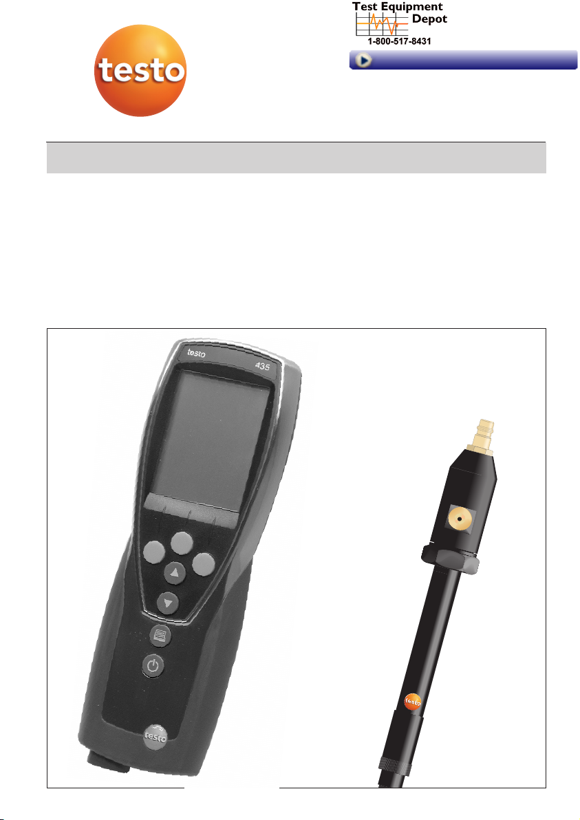
Pressure Dew Point Probe
0636.9835 / 0636.9836
Application Information en
99 Washington Street
Melrose, MA 02176
Phone 781-665-1400
Toll Free 1-800-517-8431
Visit us at www.TestEquipmentDepot.com
Page 2

Contents
Probe description.......................................................................3
User instructions ........................................................................4
Safety instructions......................................................................5
Operating instructions................................................................6
The pressure dew point probe ................................................6
Measuring ...................................................................................7
Maintenance ...............................................................................8
Control and calibration options .................................................9
Technical data ...........................................................................12
Warranty................................................................................12
Ordering data.............................................................................13
Appendix A ................................................................................14
Necessary pressure dew point values t
pd
................................14
Appendix B ................................................................................15
Dew point graph for compressed air......................................15
Measuring instrument conforms with EN 50 081-1 + EN 50 082-1
Page 3
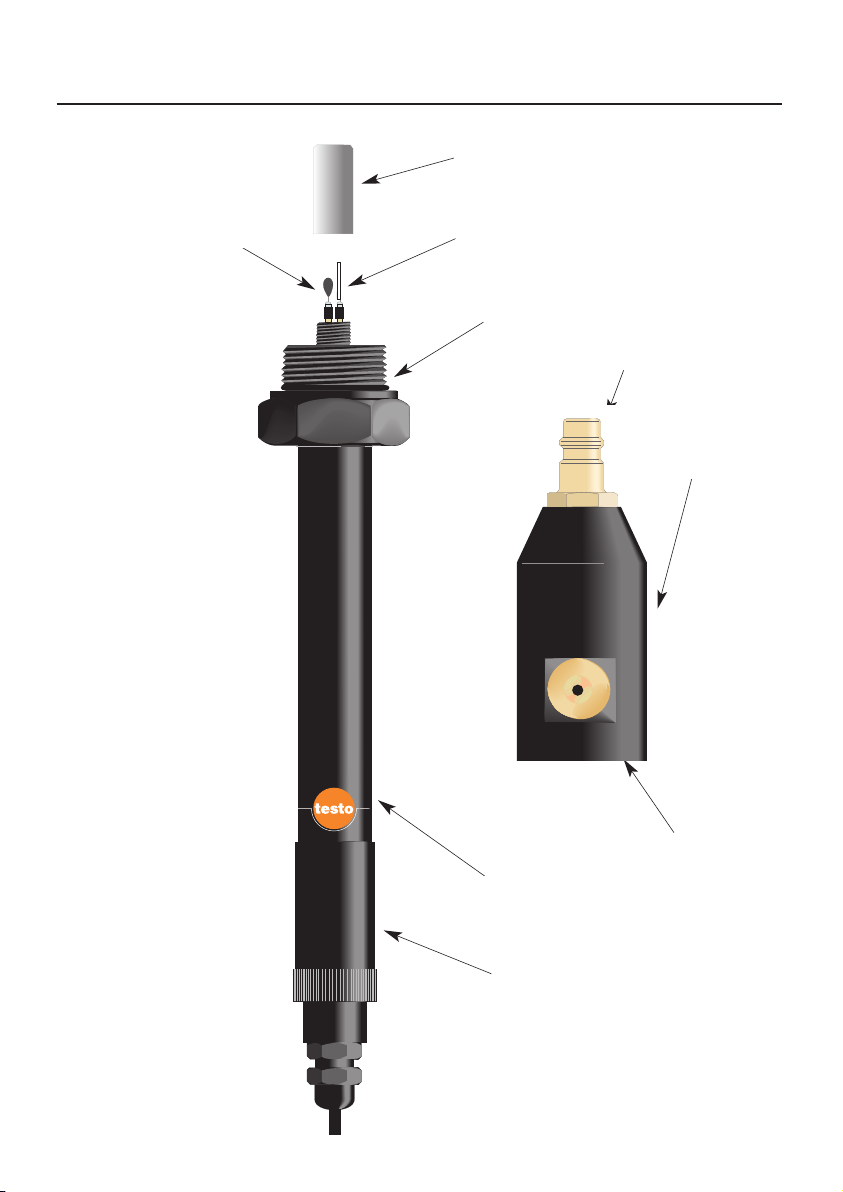
Probe description
3
PTFE sintered cap
Humidity sensor
Temperature sensor
Standard plug-in nipple
Humidity/temperature
probe
Internal thread
Measuring chamber
Protective sleeve
valve
Page 4
User instructions
The two pressure dew point probes guarantee quick
and accurate dew point measurement.
The probe was developed in cooperation with a world
market leader in the compressed air engineering
sector.
The standard probe 0636.9835 is sufficient for most
measurements in compressed-air piping (e.g.
refrigeration dryers in the range from 0 to 2 °C t
pd
).
The precision probe 0636.9836 is the ideal probe for
highly accurate measurements in the remaining
humidity range (e.g. in adsorption dryers to
-50 °C t
pd
).
The pressure dew point tpdis the temperature at which
compressed air reaches the saturation state (100%
RH). This value is an important criteria for the perfect
running of the compressed air plant.
The probe is connected to the compressed air system
via a standard plug-in connector (G1/4” internal thread
to ISO 228-1) or via a screw-on adapter for
measurements at test points. If required other
standard plug-in connectors with thread G 1/4” can be
screwed into measuring chamber.
The sensor is positioned in the flow of compressed air
being measured, for the duration of the measurement.
The probes can be used, without a measuring
chamber, in accordance with the Instruction Manual
for the testo x35 instruments.
By connecting the probe to testo x35 the user has a
portable, mains independent measuring system. The
large display enables the
display of the relative humidity or the dew point with
the temperature.
4
Page 5

Safety instructions
Read
before using the instrument
Please read the Instruction Manual belonging to the measuring instrument.
Do not exceed the permissible pressure range.
Observe the measuring range of the sensor.
Overheating can destroy the probe.
Observe the permissible storage and transport temperature
as well as the permissible operating temperature
(e.g. protect the measuring instrument from direct sunlight).
If the instrument is opened, improperly handled of if force is applied,
the warranty will no longer be valid.
5
Page 6

Operating instructions
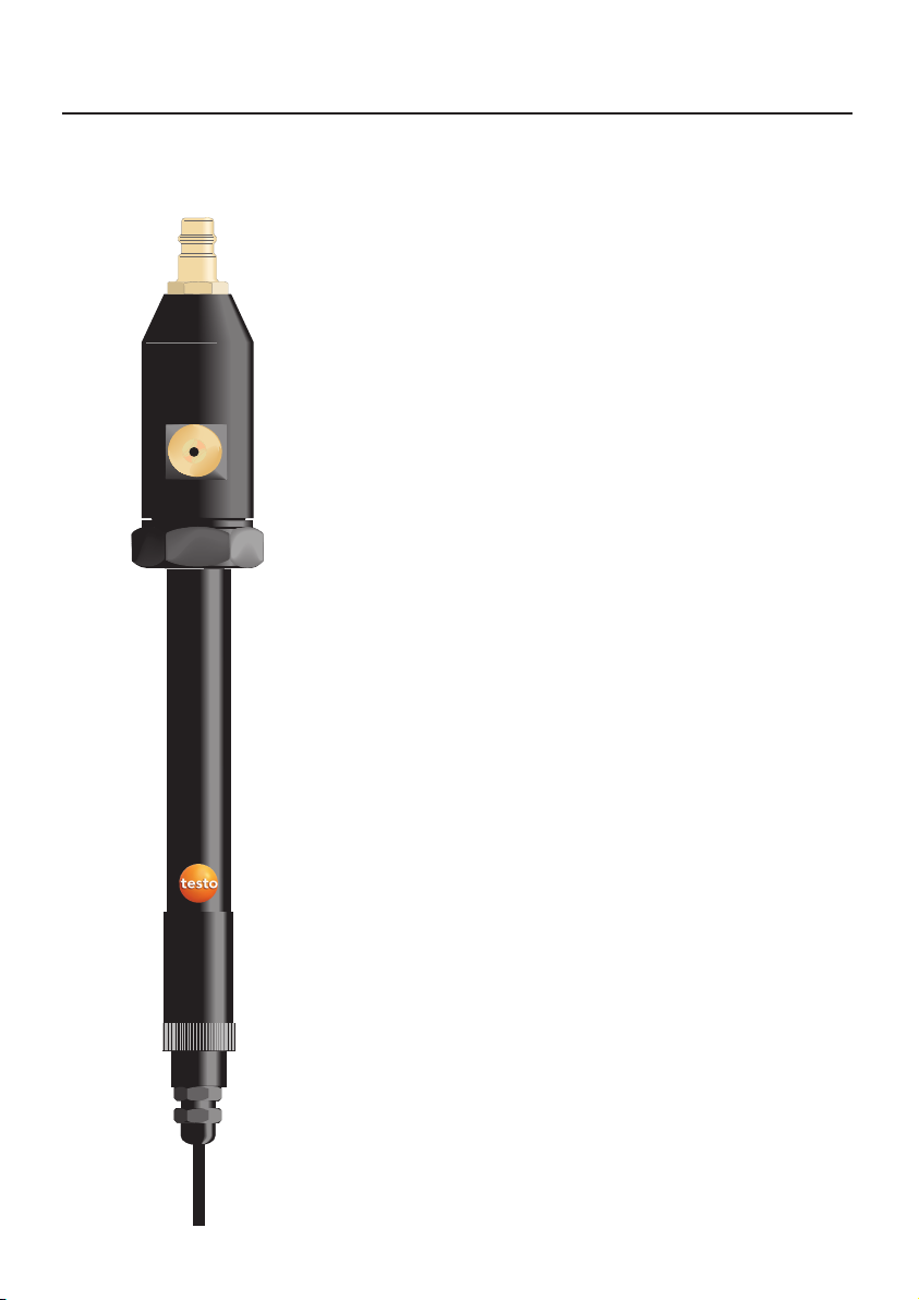
The pressure dew point probe
Place the measuring chamber on the humidity probe
adapter and screw on tightly by hand.
The humidity probe can also be used without the PTFE
sintered cap, in which case the response times are
shorter. However, the probes can become dirty or
damaged during assembly or application.
If possible always use a sintered cap with the probe. A
metal protection cage (Order no. 0554.0755) can be
used with absolute oil-free compressed air.
Connect the probe to the instrument
In order to obtain a real measuring value, let
compressed air escape from the outlet for about 10
seconds.
Connect the humidity probe to the compressed air
plant. Compressed air flows out of the capillary wire
(shortening of the response times).
6
Make sure that the measuring chamber and
the valve are not dirty.
The reduction of pressure at the outlet leads to a
physical reduction in the pressure dew point value.
See the table in appendix B.
s
s
s
s
s
s
s
s
s
s
s
s
s
s
s
s
s
Valve to
control the
air flow rate
Using the valve you are able to control the air
flow rate which flows off to get an optimized
response time with the humidity sensor
Page 7

Measuring
The response time is 1 to 5 minutes (typically
2 minutes). Wait until the measured values are
stable (approx. 60 s without a change in the
measured values).
7
The storage of the humidity probe in areas with
temperature and humidity values which differ
considerably from those of the compressed air
being measured, and dirty sensors or sintered
caps increase the response times.
Please read the instrument instruction manual
before the switching on the instrument, in order
to avoid incorrect measuring results and
damage to the instrument.
Page 8

Maintenance
A robust, long-term stable humidity sensor is located
in the probe head.
Depending on the application and dirt which has
gathered, we recommend a quarterly to yearly control
with our 0554.0660 control and calibration set. See
the instructions on page 10.
Clean dirty sensors with alcohol (isopropanol) or
distilled water.
Unscrew the measuring chamber and the PTFE
sintered cap.
Dip the sensor in the alcohol, rinse in distilled water
and then leave to dry in the air.
Put the PTFE sintered cap back on and screw tightly.
Faulty sensors can be replaced, please contact our
service department.
Dirty PTFE sintered caps can also be cleaned in
alcohol or in distilled water. Impurities can be blown
out with compressed air. Always blow out the cap
from the inside.
Dirty measuring chambers can also be cleaned in
alcohol or in distilled water, or purged with
compressed air.
Should the measuring chamber be faulty, please
contact our service department.
8
Do not touch or knock the sensor.
Page 9

Control and calibration options
The control and calibration set (Order no.: 0554.0660)
is used to control and calibrate humidity probes. The
set consists of two special containers.
With the aid of different saline solutions, air mixtures
with defined relative humidities are produced (for
additional information see the Instruction Manual
“Control and calibration set for humidity sensors”).
As part of the accreditation as a calibration laboratory
for the parameters “Relative humidity” and
“Dew point” the values for the relative humidity over
the saturated lithium chloride (LiCl) and sodium
chloride (NaCl) solutions were newly specified at testo.
These improved values also apply to all of the control
and calibration sets already delivered. Ignore the
values specified up to now.
9
LiCl 11.3%RH, NaCl 75.3%RH
at rated temperature +25 °C
Temperature dependencies
Lithium chloride
Temperature LiCl
Average Tolerance
10 °C 11.29 % ± 0.41 %
15 °C 11.30 % ± 0.35 %
20 °C 11.31 % ± 0.31 %
25 °C 11.30 % ± 0.27 %
30 °C 11.28 % ± 0.24 %
Sodium chloride
Temperature NaCl
Average Tolerance
10 °C 75.67 % ± 0.22 %
15 °C 75.61 % ± 0.18 %
20 °C 75.47 % ± 0.14 %
25 °C 75.29 % ± 0.12 %
30 °C 75.09 % ± 0.11 %
Page 10

Control and calibration options
General information
The humdity probes 0636.9835 and 0636.9836
undergo a comprehensive calibration procedure at
testo. Before control and calibration, the probes must
be stored at a constant temperature (+20 to +30 °C)
for approximately 12 hours. The minimum adjustment
time is 15 minutes in the test container with screwed in
probes.
Control and/or calibration
Standard probe 0636.9835
- Carefully screw off the PTFE sintered cap
- Screw off the protective sleeve
- Screw the probe into the test container LiCl (11.3%)
- 15 minute adjustment time
- Control on the hand-held instrument display
- Calibrate, if necessary, by pressing
P1 = 11.3%RH ± 2%RH
- Screw out the probe from the LiCl test container
- Screw the probe into the NaCl (75.3%) test
container
- 15 minute adjustment time
- Control on the hand-held instrument display
- Calibrate, if necessary, by pressing
P2 = 75.3%RH ± 2%RH
- Screw out the probe from the NaCl test container
- Carefully screw on the PTFE sintered cap
- Screw on the protective sleeve tightly
Precision probe 0636.9836
In addition to the standard calibration the precision
probe is subjected to a fine calibration in the factory at
-40 °C pressure dew point.
A control with the control and calibration set is
possible. The salt containers are not suitable for
calibrating the precision probe. A precision calibration
can only be carried out at testo or with corresponding
highly accurate reference systems (dew point mirror
measuring instruments for compressed air).
10
P1
P2
Protective
sleeve
Page 11

Control and calibration options
Fine calibration
With the probes 0636.9835 and 0636.9836 you have
the option of a fine calibration on any pressure dew
point in the range -50 to +25 °C t
pd
at +25 °C (one
point calibration).
Note
A fine calibration is practical only if used with highly
accurate reference systems and if the appropriate
adjustment times are taken into consideration (at least
15 minutes). The probe 0636.9836 is already
optimized in the factory for humidity measurement in
compressed air systems.
How to carry out a fine calibration
- Screw off the protective sleeve
- Turn the switch right to “Offset”
- Mark down the measured values via P1 (Down)
- Mark up the measured values via P2 (Up)
The values set last on the hand-held instrument
display are saved.
Factory setting
The set fine correction is inactive if the switch is turned
to the left (switch position “Calibration”).
11
Off On
m/s
Off
Offset
Abgleich
Calibration
Etalonnage
11,3%
(DOWN)
75,3%
(UP)
Page 12

Warranty
Pressure dew point probe ................1 year
Measuring chamber .........................1 year
If the instrument is opened, improperly handled or if force is applied, the
warranty will be no longer valid.
12
Technical data
Sensor:............................................testo®ceramic sensor
Measuring range: ...........................0 to 100 %RH,
Pressure dew point tpd: .....................-60 to +50 °C t
pd
Pressure range: ..............................Overpressure to 15 bar
Accuracy, temperature:*................±0.4 °C
Resolution: .....................................0.1 %RH / 0.1 °C
Temperature range: .......................Probe: -20 to +50 °C
Instrument: 0 to +40 °C
Control point: .................................11.3 to 75.3%RH
Measuring air flow rate
at 6.0 bar overpressure: ................1,0 l/min factory set at
........................................................delivery (relating to 0 bar,
........................................................+20°C)
Response time: ..............................1 to 5 min
typically 2 min
Storage/transport temperature: ....-20 to +70°C
Accuracy:
* Accuracy referred to a rated temperature of +25 °C.
The Technical data applies in connection with the testo x35
measuring instrument.
5
0
-5
-10
-20
-30
-40
±0.9
±1
±2
±3
±4
-
-
±0.8
±0.8
±0.9
±1
±2
±3
±4
Accuracy
in °C t
pd
0636.9835 0636.9836
Pressure
dew point
in °C
Page 13

13
Ordering data
Description ..................................................Order no.
Standard probe ......................................0636.9835
Measuring chamber, Instruction Manual
Precision probe ......................................0636.9836
Measuring chamber, Instruction Manual
Measuring chamber ..............................0554.3303
Humidity sensor ......................................0420.0023
Temperature sensor................................0420.1242
Humidity control and calibration set ........0554.0660
11.3%RH, 75.3%RH, Instruction Manual
PTFE sintered cap ................................0554.0756
Metal protection cage ............................0554.0755
Calibration certificate..............................0520.0306
Page 14

14
Appendix A
Necessary pressure dew point values t
pd
Depending on the type of application, different requirements can be
made on the air quality.
As the speed of corrosion on steel surfaces increases rapidly above
approx. 50%RH, this value should never be exceeded.
Field of application Necessary pressure dew point values t
pd
Factory air, internal pipes 10 °C to -10 °C
Paint spraying 10 °C to -25 °C
Instrument air 10 °C to -40 °C
Sand blasting machine 5 °C to 0 °C
Pneumatic tools 5 °C to -25 °C
Pneumatic conveyor belt 5 °C to -60 °C
Transport vehicles (bus, etc.) -13 °C to -33 °C
Cleaning of optical systems -17 °C to -33 °C
Drying of electronic components -20 °C to -40 °C
Factory air, external pipes -20 °C to -40 °C
Chem. and pharmaceutical plants -25 °C to -40 °C
The pressure dew point t
pd
is the temperature at which the compressed
air is fully saturated (100 %RH) .
Page 15

15
Appendix B
Dew point graph for compessed air
1
23457101420
01234691319
0,1
0,2
0,3
0,4
0,5
0,7
1,0
2
3
4
5
7
10
20
30
40
50
70
100
-10
-5
0
2
6
10
15
20
25
30
35
40
45
50
55
60
65
70
45
40
35
30
25
20
15
10
6
2
0
-5
-10
-15
-20
-25
-30
50
55
70
Gramm Wasserdampf je m
3
feuchtigkeitsgesättigter Druckluft ( )
g
m
3
65
60
Drucktaupunkt (°Ctd)
This graph gives information on the change in
the pressure dew point at pressure loss. A drop
in working pressure from 8 bar to 6 bar is used
as an example here. In this case the pressure
dew point is reduced from 10 °C to 5 °C.
The water content falls from 9 g/m
3
to 7g/m3.
The values refer to an ambient
temperature of +25 °C.
Grammes of water vapour per m
3
of humidity-saturated compressed air
Pressure dew point (°Ctd)
AIR PRESSURE (bar)
Working pressure
Test Equipment Depot - 800.517.8431 - 99 Washington Street Melrose, MA 02176
TestEquipmentDepot.com
 Loading...