

Page 1

testo 160
Instruction manual
Find Quality Products Online at: [email protected]
www.GlobalTestSupply.com
Page 2
Contents
1 Safety and waste disposal ................................................................... 5
2 Description of the instrument ............................................................... 7
3 Technical data ................................................................................... 14
4 Operation ........................................................................................... 22
Contents
1.1 About this document .............................................................................. 5
1.2 Symbols and writing standards .............................................................. 5
1.3 Safety ..................................................................................................... 5
1.4 Warning notices ..................................................................................... 6
1.5 Disposal ................................................................................................. 6
2.1 Using the testo 160 ................................................................................ 7
2.2 WiFi data loggers ................................................................................... 7
2.2.1 testo 160 TH ............................................................................ 7
2.2.2 testo 160 E .............................................................................. 8
2.2.3 testo 160 THE .......................................................................... 8
2.2.4 testo 160 THL .......................................................................... 9
2.2.5 testo 160 IAQ ......................................................................... 10
2.3 External probes .................................................................................... 10
2.3.1 S-TH ...................................................................................... 11
2.3.2 S-LuxUV ................................................................................ 12
2.3.3 S-Lux ..................................................................................... 12
2.3.4 Extension cable ..................................................................... 13
2.4 Deco-covers ......................................................................................... 13
3.1 WiFi data loggers ................................................................................. 14
3.2 External probes .................................................................................... 18
3.3 Deco-covers ......................................................................................... 21
4.1 Commissioning .................................................................................... 22
4.2 Logging into the Testo Cloud ............................................................... 24
4.2.1 Configuration via the Setup assistant .................................... 24
4.2.2 Configuration via the web interface (WPA2 Personal) ........... 25
4.2.3 Configuration via the testo Saveris 2 App ............................. 26
4.2.4 Offline configuration via PDF form ......................................... 28
4.3 Logging WiFi data loggers out of the Testo Cloud ............................... 29
4.4 Status LED signals ............................................................................... 30
Find Quality Products Online at: [email protected]
www.GlobalTestSupply.com
Page 3
Contents
4.5 Inserting into/removing from the wall bracket ..................................... 31
4.5.1 Installing the probe on the data logger ................................. 31
4.5.2 Changing batteries ................................................................ 32
4.5.3 Deco-cover installation ......................................................... 32
4.5.4 Wall bracket .......................................................................... 33
4.6 testo Saveris 2 App ............................................................................. 34
4.6.1 Receiving push alerts ............................................................ 34
4.6.2 Network analysis ................................................................... 34
4.7 Analysis and reports (web) .................................................................. 34
4.8 Alarms ................................................................................................. 36
4.8.1 Alarm list ............................................................................... 36
4.8.2 Alarm settings ....................................................................... 37
4.8.2.1 Creating and displaying alarm settings ................ 37
4.8.2.2 Configuring and editing a displayed alarm setting
............................................................................. 37
4.9 System warnings ................................................................................. 39
4.9.1 Creating and displaying system warnings ............................ 39
4.9.2 Configuring and editing a displayed system warning ........... 39
4.10 Configuration ....................................................................................... 40
4.10.1 Standard users ...................................................................... 40
4.10.2 Creating and editing new users ............................................ 40
4.10.3 User roles .............................................................................. 41
4.10.4 User management ................................................................. 43
4.10.4.1 User settings ........................................................ 43
4.10.4.2 Account information ............................................. 43
4.10.4.3 Change password ................................................ 43
4.10.4.4 Logoff ................................................................... 43
4.10.5 Account ID ............................................................................ 43
4.10.6 Creating and editing a measuring point group...................... 43
4.10.7 Areas ..................................................................................... 44
4.10.7.1 Creating and editing areas ................................... 44
4.10.7.2 Deleting an area ................................................... 45
4.10.8 WiFi data loggers .................................................................. 45
4.10.9 Firmware updates ................................................................. 46
4.11 Command bar ...................................................................................... 46
Find Quality Products Online at: [email protected]
www.GlobalTestSupply.com
Page 4
Contents
5 FAQ ................................................................................................... 48
6 Cloud licences ................................................................................... 52
7 Authorizations .................................................................................... 52
4.11.1 Opening the Setup assistant ................................................. 46
4.11.2 Opening the Online Help ....................................................... 47
4.11.3 Opening system messages ................................................... 47
4.12 System and status information ............................................................ 47
Find Quality Products Online at: [email protected]
www.GlobalTestSupply.com
Page 5
1 Safety and waste disposal
1 Safety and waste disposal
1.1 About this document
Use
1.2 Symbols and writing standards
…
Result of an action
Requirement
1.3 Safety
General safety instructions
• The instruction manual is an integral part of the instrument.
• Pay particular attention to the safety instructions and warning notices in
order to prevent injuries or damage to the product.
• Keep this documentation to hand so that you can refer to it when
necessary.
• Always use the complete original instruction manual.
• Hand this documentation on to any subsequent users of the product.
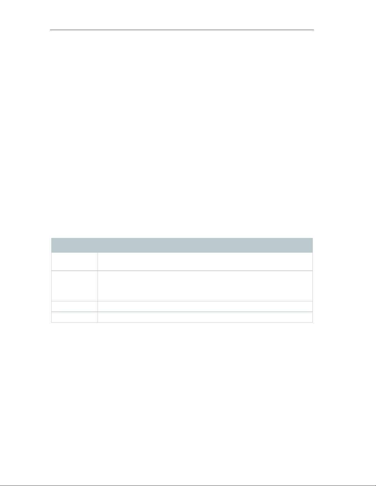
Display Explanation
Note: basic or further information
1.
Action: several steps, the sequence must be followed.
2.
• Only operate the product properly, for its intended purpose, and within the
parameters specified in the technical data. Do not apply any force.
• Do not operate the instrument if there are signs of damage on the housing.
• Dangers may also arise from the systems to be measured or from the
measuring environment: Always comply with the locally valid safety
regulations when carrying out measurements.
5
Find Quality Products Online at: [email protected]
www.GlobalTestSupply.com
Page 6
1 Safety and waste disposal
Batteries
1.4 Warning notices
CAUTION
Indicates possible damage to equipment
1.5 Disposal
• Temperature information given on probes/sensors relates only to the
measuring range of the sensor technology. Do not expose handles and feed
lines to temperatures in excess of 70 °C (158°F), unless they are expressly
authorised for use at higher temperatures.
• Do not carry out any contact measurements on uninsulated, live parts.
• Do not store the product together with solvents. Do not use any desiccants.
• Only perform that maintenance and repair work on this instrument which is
described in the documentation. Follow the prescribed steps exactly when
doing the work. Use only original spare parts from Testo.
• Improper use of batteries may cause destruction of the batteries, injuries
due to current surges, fire or the escape of chemicals.
• Only use the batteries supplied in accordance with the instructions in the
instruction manual.
• Do not short-circuit the batteries.
• Do not take the batteries apart and do not modify them.
• Do not expose the batteries to heavy impacts, water, fire or temperatures in
excess of 55 °C.
• Do not store the batteries near any metal objects.
• In the event of contact with battery acid: rinse affected areas thoroughly
with water, and if necessary consult a doctor.
• Do not use any leaky or damaged batteries.
Always pay attention to any information marked with the following warning
notices along with warning pictograms. Implement the specified precautionary
measures!
• Dispose of spent batteries in accordance with the relevant legal
specifications.
6
Find Quality Products Online at: [email protected]
www.GlobalTestSupply.com
Page 7
2 Description of the instrument
2 Description of the instrument
2.1 Using the testo 160
2.2 WiFi data loggers
2.2.1 testo 160 TH
160 TH data logger to carry out temperature and
• At the end of its useful life, deliver the product to the separate collection
point for electric and electronic devices (observe local regulations) or return
the product to Testo for disposal.
The testo 160 WiFi data logger system is a modern solution for monitoring the
climate and lighting conditions, e.g. in museums, archives, galleries and
libraries.
The system consists of WiFi data loggers, external probes and a Cloud data
storage system. The testo 160 WiFi data loggers reliably record temperature
and humidity, CO
and transmit the readings directly to the Testo Cloud via WLAN. Via the web
interface of this Cloud, the data can be analyzed at any time and anywhere,
using an internet-ready smartphone, tablet or PC. The WiFi data loggers are
programmed and reports are generated via this interface. Limit value violations
are immediately reported via e-mail or optionally via SMS, and alarm
notifications are possible via Push (Saveris 2 App).
levels, illuminance and UV radiation at adjustable intervals
2
You can use the testo
humidity measurements.
Element Element
7
Find Quality Products Online at: [email protected]
www.GlobalTestSupply.com
Page 8
2 Description of the instrument
1
and relative humidity
2
2.2.2 testo 160 E
1
sensor
2
3
2.2.3 testo 160 THE
Internal sensors for temperature
The external probes S-TH, S-LuxUV and S-Lux can be connected to
the testo 160 E WiFi data logger.
Element Element
Micro-USB port
Connector socket for external
Connector socket for external
sensor
You can use the testo 160 THE WiFi data logger to carry out
temperature and humidity measurements. The external probes S-TH,
S-LuxUV or S-Lux can also be connected.
USB connection
Element Element
8
Find Quality Products Online at: [email protected]
www.GlobalTestSupply.com
Page 9
2 Description of the instrument
1
and relative humidity
2
sensor
3
4
sensor
2.2.4 testo 160 THL
1
UV sensor
2
Lux sensor
3
4
Internal sensor for temperature
USB connection
You can use the testo 160 THL WiFi data logger to measure
temperature, humidity, illuminance and UV radiation.
Connector socket for external
Connector socket for external
Element Element
Internal sensor for temperature
USB connection
and relative humidity
9
Find Quality Products Online at: [email protected]
www.GlobalTestSupply.com
Page 10
2 Description of the instrument
2.2.5 testo 160 IAQ
1
2
3
4
5
QR code
6
Button
7
8
If the WiFi data logger is in Single Mode (without external power supply
2.3 External probes
You can use the testo 160 IAQ WiFi data logger to carry out
temperature, humidity, carbon dioxide concentration and atmospheric
pressure measurements.
Element Element
Status LED
Air quality light
USB connection
Display
CO2 sensor
Internal sensor for temperature
and relative humidity
If the WiFi data logger is in Continuous Mode (external power supply
via USB mains unit), the air quality light stays on permanently.
Temperature and humidity readings are displayed alternately.
via USB mains unit), the air quality light only comes on briefly during
the measurement. Only the temperature is displayed. When switching
to Single Mode, the WiFi data logger does not supply any readings for
at least 10 min. “CAL” is shown on the display until the next
measurement.
The external probes S-TH, S-LuxUV and S-Lux extend the range of functions of
the 160 THE WiFi data logger and, in conjunction with the 160 E WiFi data
logger, form an extremely versatile measurement system.
10
Find Quality Products Online at: [email protected]
www.GlobalTestSupply.com
Page 11

The external probes are only approved in conjunction with the
2.3.1 S-TH
To make it easy to install, the probe can be pushed out of the wall
1
Sensor
2
Screw thread
3
4
testo 160 THE and testo 160 E WiFi data loggers.
The external probe S-TH can be connected to the following WiFi data
loggers: testo 160 THE and testo 160 E. You can use the S-TH probe
to carry out temperature and humidity measurements.
bushing. The probe can also be used without this wall bushing.
2 Description of the instrument
Element Element
Securing nut
Jack plug
11
Find Quality Products Online at: [email protected]
www.GlobalTestSupply.com
Page 12
2 Description of the instrument
2.3.2 S-LuxUV
1
Lux sensor
2
UV sensor
3
Jack plug
2.3.3 S-Lux
The external probe S-LuxUV can be connected to the following WiFi
data loggers: testo 160 THE and testo 160 E. You can use the SLuxUV probe to carry out illuminance and UV measurements.
Element Element
The external probe S-Lux can be connected to the following WiFi data
loggers: testo 160 THE and testo 160 E. You can use the S-Lux probe
to carry out illuminance measurements.
Element Element
12
Find Quality Products Online at: [email protected]
www.GlobalTestSupply.com
Page 13
2 Description of the instrument
1
2
2.3.4 Extension cable
The sensors are supplied with the 60 cm cable (0554 2004) as
combined. The maximum total length is approx. 10 m.
2.4 Deco-covers
Lux sensor
Jack plug
standard. A 2.5 m long cable is optionally available (0554 2005), to be
able to adapt the measurement system to all measuring situations.
Since these are digital probes, multiple extension cables can also be
3 different deco-covers are optionally available. Cover 0554 2006 is intended
for the testo 160 TH, testo 160 THE and testo 160 E WiFi data loggers. Cover
0554 2009 is intended for the testo 160 THL WiFi data logger and cover 0554
2012 for the testo 160 IAQ WiFi data logger.
13
Find Quality Products Online at: [email protected]
www.GlobalTestSupply.com
Page 14
3 Technical data
3 Technical data
3.1 WiFi data loggers
Measurement-specific data
CAUTION
Damage to the humidity probe
Temperature measurement
Measuring range
-10 °C to 50 °C
see ext. probes
Accuracy
± 0.5 °C
Resolution
0.1 °C
Humidity measurement
± 1% RH/year drift
Lux measurement
Measuring range
see ext. probes
see ext. probes
Accuracy
Resolution
UV measurement
Measuring range
see ext. probes
see ext. probes
The humidity sensor attains the highest degree of accuracy in
temperatures between + 5 °C and + 60 °C and 20% to 80% RH. If the
instrument is exposed to higher humidity for a long period of time, this
can falsify the readings by up to 3% RH. After 48 hours at 50% RH ±
10 % and +20 °C ± 5 °C, the sensor regenerates by itself.
- The probe must never be exposed to a humidity level of 100 % RH for
longer than 3 days.
WiFi data loggers testo 160 TH testo 160 THE testo 160 E
Order number 0572 2021 0572 2023 0572 2022
Measuring range 0 to 100% RH (non-condensing) see ext. probes
Accuracy ± 2% RH @ 25 °C & 20 to 80% RH
± 3% RH @ 25 °C & <20% RH &
>80% RH
± 1% RH hysteresis
Resolution 0.1% RH
Accuracy
Resolution
Find Quality Products Online at: [email protected]
14
www.GlobalTestSupply.com
Page 15
3 Technical data
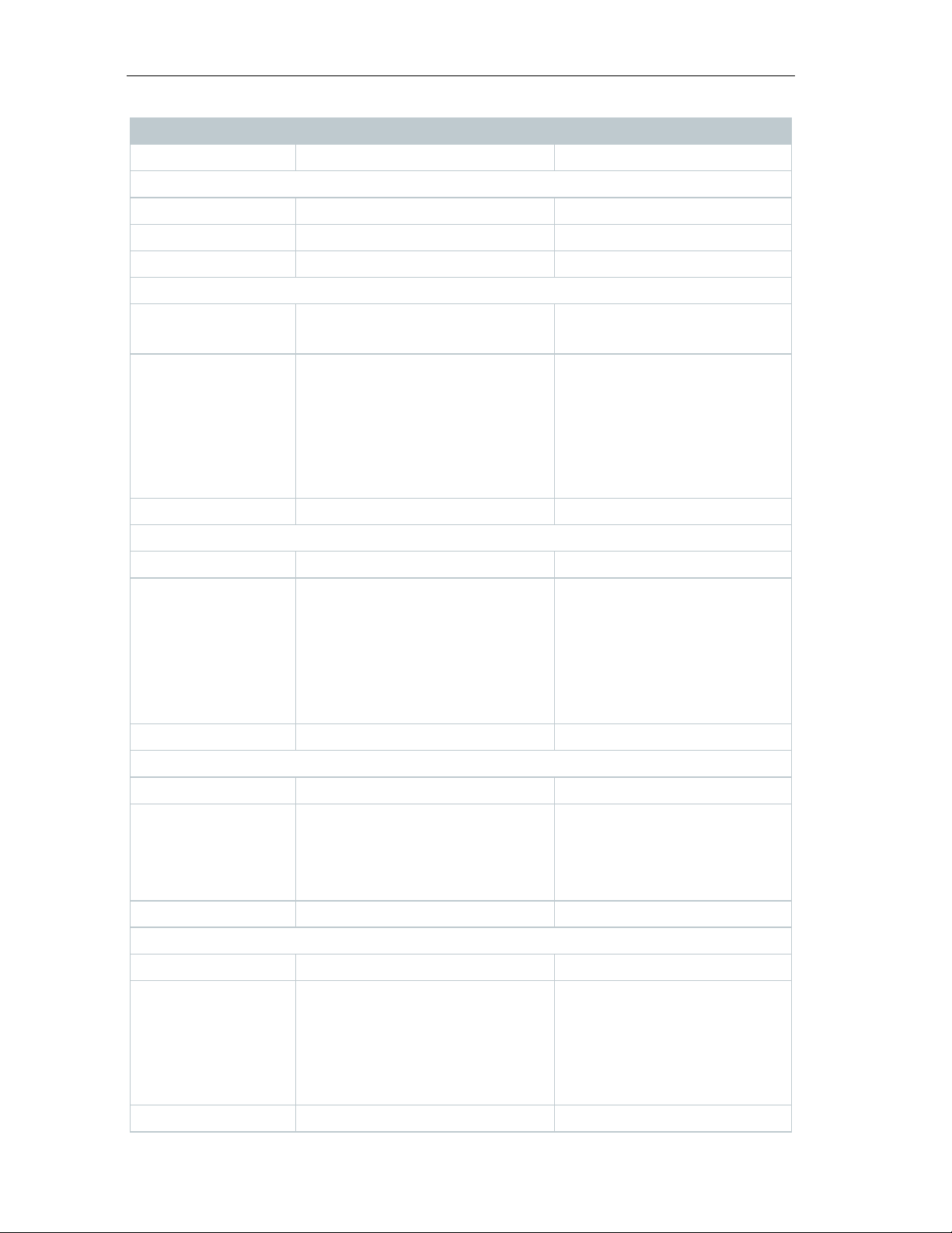
Order number
0572 2014
0572 2024
Temperature measurement
Measuring range
0 °C to 50 °C
-10 °C to 50 °C
Accuracy
± 0.5 °C
± 0.5 °C
Resolution
0.1 °C
0.1 °C
Humidity measurement
condensing)
condensing)
Resolution
0.1% RH
0.1% RH
Lux measurement
Measuring range
0 to 20,000 lux
UV measurement
Measuring range
0 to 10,000 mW/m2
22 °C)
Resolution
0.1 mW/m2
CO2 measurement
reading) (@ 25 °C)
WiFi data loggers testo 160 IAQ testo 160 THL
Measuring range 0 to 100% RH (non-
Accuracy ± 2% RH @ 25 °C & 20 to
80% RH
± 3% RH @ 25 °C & <20%
RH & >80% RH
± 1% RH hysteresis
± 1% RH / year drift
Accuracy DIN 5032-7 Class C-
Resolution 0.1 lux
0 to 100% RH (non-
± 2% RH @ 25 °C & 20 to
80% RH
± 3% RH @ 25 °C & <20%
RH & >80% RH
± 1% RH hysteresis
± 1% RH/year drift
compliant or:
± 3 lux or ± 3% of the
reading (based on the
external reference DIN
5032-7 Class L)
Accuracy ± 5 mW/m2 or 5% of the
reading (based on the
external reference at
Measuring range 0 to 5,000 ppm
Accuracy ± (50 ppm + 3% of the
reading) (@ 25 °C)
Battery-operated:
± (100 ppm + 3% of the
Resolution 1 ppm
Find Quality Products Online at: [email protected]
www.GlobalTestSupply.com
15
Page 16
3 Technical data
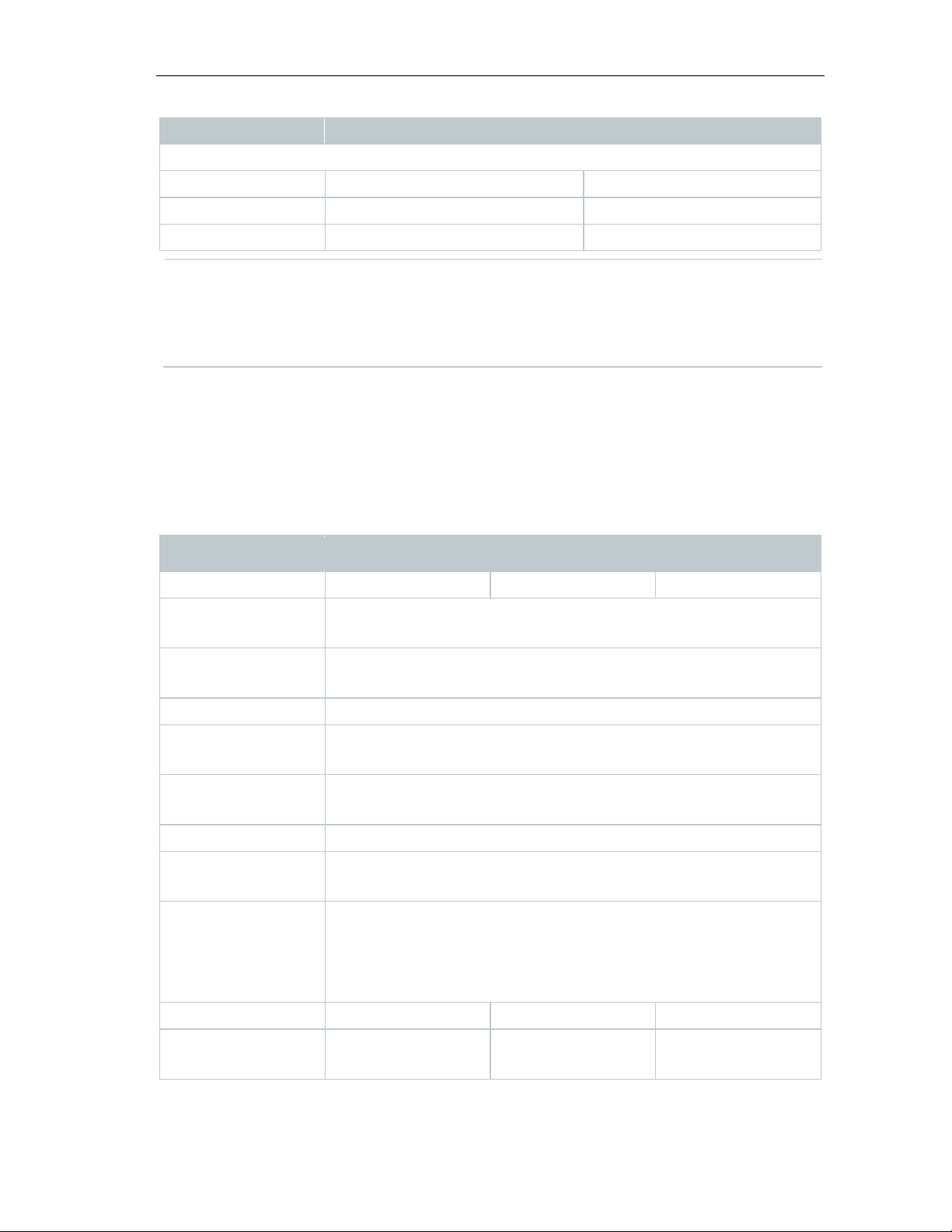
Pressure
Measuring range
600 to 1100 mbar
Accuracy
± 3 mbar @ 22 °C
Resolution
1 mbar
General data
Order number
0572 2021
0572 2023
0572 2024
temperature
temperature
Protection class
IP20
WiFi data loggers testo 160 IAQ testo 160 THL
The time between the system warning "Battery almost discharged”
and "Measurement data stop" is at the most one day during standard
operation and a measuring cycle & communication cycle of 1 min (day
& night) (battery type: Varta Industrial).
testo 160 WiFi data loggers come with a factory calibration protocol as
standard. For museums, we recommend having an annual test carried out by
Testo Customer Service. Moreover, there is an option of having ISO certificates
created for the WiFi data loggers. These can be implemented by Testo
Industrial Services (TIS) .
WiFi data loggers testo 160 TH testo 160 THE testo 160 THL
Operating
Storage
-10 °C to 50 °C
-20 °C to 50 °C
Measuring cycle Depends on the Cloud licence
Basic: 15 min to 24 h / Advanced 1 min to 24 h flexible
Communication
cycle
Basic: 15 min to 24 h / Advanced 1 min to 24 h flexible
Depends on the Cloud licence
Memory 32,000 readings (sum of all channels)
Voltage supply 4 x AAA batteries 1.5 V
Alternatively mains unit via USB connection
Battery life 18 months
At +25 °C, 15-minute measuring cycle and 6-hour
communication cycle
(depending on the WLAN structure)
Dimensions 64 x 76 x 22 mm 64 x 76 x 22 mm 64 x 92 x 24 mm
Weight including
batteries
94 g 94 g 113 g
16
Find Quality Products Online at: [email protected]
www.GlobalTestSupply.com
Page 17
3 Technical data
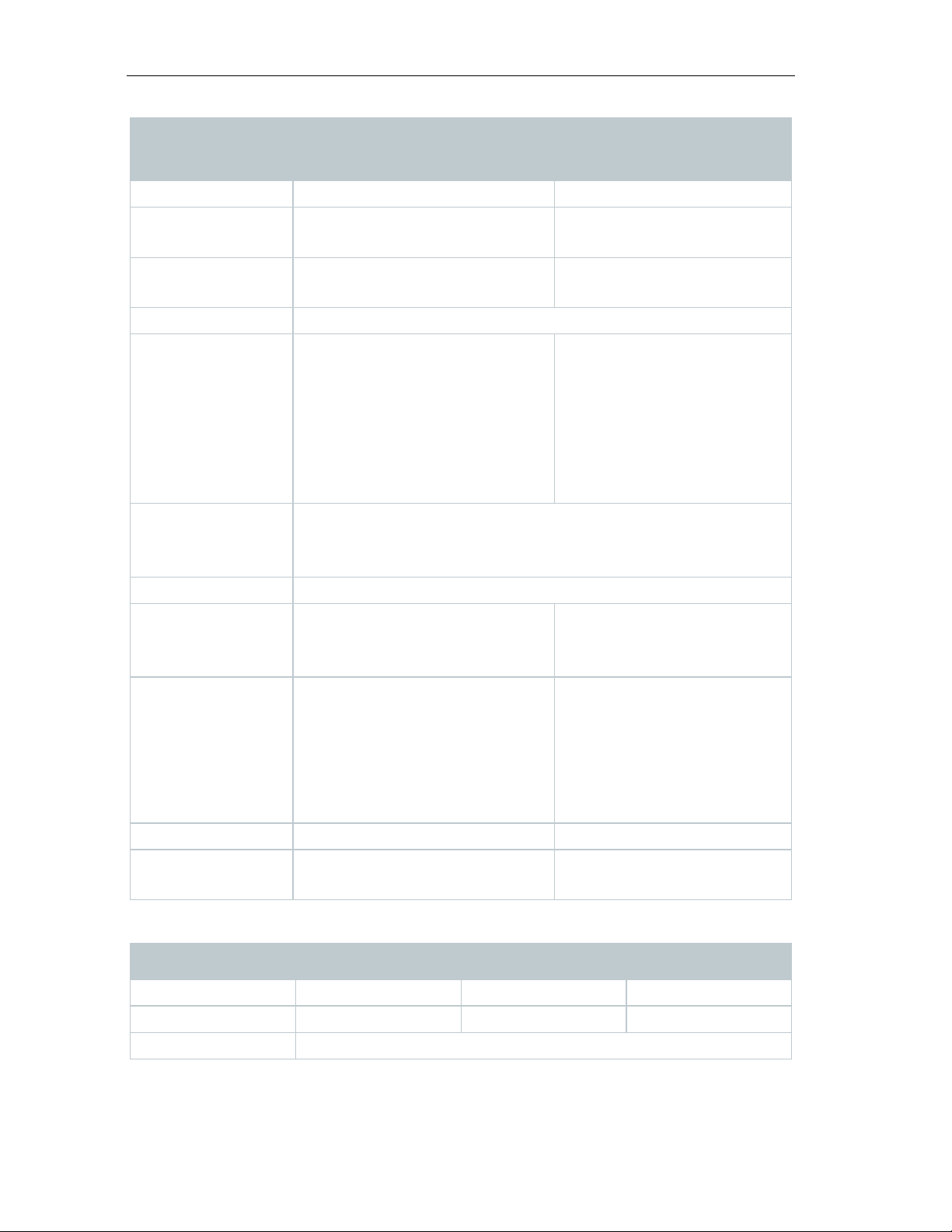
Order number
0572 2014
0572 2022
temperature
Protection class
IP20
flexible (battery operation)
Advanced 1 min to 24 h flexible
USB connection
USB connection
reception quality)
reception quality)
batteries
WiFi-specific data
Order number
0572 2021
0572 2023
0572 2024
WLAN
Standard
802.11 b/g/n
WiFi data
testo 160 IAQ testo 160 E
loggers
Operating
Storage
0 °C to 50 °C -10 °C to 50 °C
0 °C to 50 °C -20 °C to 50 °C
temperature
Measuring cycle Depends on the Cloud
licence
Basic: 15 min to 24 h /
Advanced 1 min to 24 h
flexible (mains operation)
Advanced 5 min to 24 h
Communication
cycle
Depends on the Cloud licence
Basic: 15 min to 24 h /
Depends on the Cloud
licence
Basic: 15 min to 24 h /
Advanced 1 min to 24 h
flexible
Memory 32,000 readings (sum of all channels)
Voltage supply 4 x AA batteries
Battery life 12 months at +25 °C,
Dimensions 82 x 117 x 32 mm 64 x 76 x 22 mm
Weight including
WiFi data loggers testo 160 TH testo 160 THE testo 160 THL
4 x AAA batteries 1.5V
Alternatively mains unit via
Alternatively mains unit via
18 months at +25 °C,
15-minute measuring cycle
and 8-hour communication
cycle
(depending on the WLAN
15-minute measuring
cycle and 6-hour
communication cycle
(depending on the WLAN
269 g 96 g
17
Find Quality Products Online at: [email protected]
www.GlobalTestSupply.com
Page 18
3 Technical data
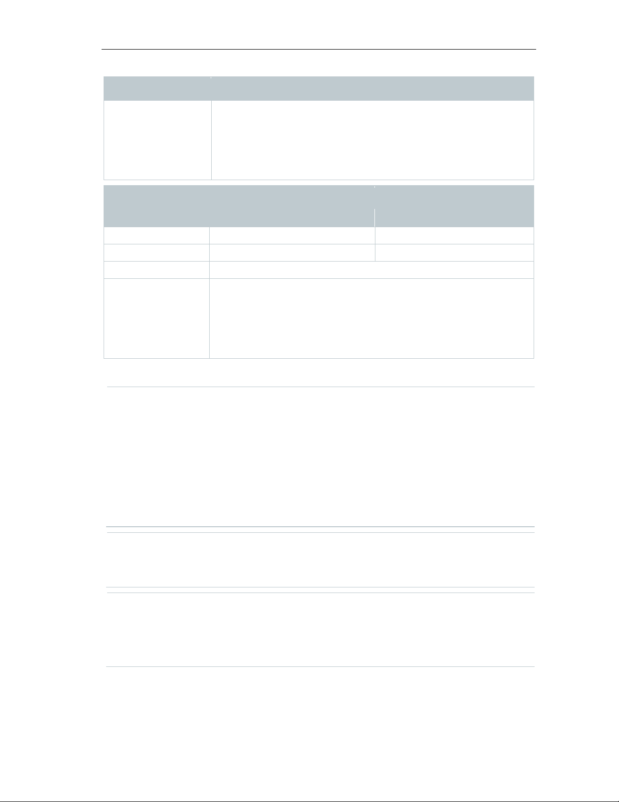
Order number
0572 2014
0572 2022
WLAN
Standard
802.11 b/g/n
WPA Personal, WPA2 (AES), WPA (TKIP), WEP
Technical data for a secure wireless LAN
Ports
No bi-directional port approvals are necessary.
During the initial configuration, it is possible to select whether DHCP or
testo 160 application
3.2 External probes
Measurement-specific data
WiFi data loggers testo 160 TH testo 160 THE testo 160 THL
Security WPA2 Enterprise: EAP-TLS, EAP-TTLS-TLS, EAP-TTLS-
MSCHAPv2, EAP-TTLS-PSK, EAP-PEAP0-TLS, EAPPEAP0-MSCHAPv2, EAP-PEAP0-PSK, EAP-PEAP1-TLS,
EAP-PEAP1-MSCHAPv2, EAP-PEAP1-PSK;
WPA Personal, WPA2 (AES), WPA (TKIP), WEP
WiFi data
testo 160 IAQ testo 160 E
loggers
Security
WPA2 Enterprise: EAP-TLS, EAP-TTLS-TLS, EAP-TTLSMSCHAPv2, EAP-TTLS-PSK, EAP-PEAP0-TLS, EAPPEAP0-MSCHAPv2, EAP-PEAP0-PSK, EAP-PEAP1-TLS,
EAP-PEAP1-MSCHAPv2, EAP-PEAP1-PSK;
The testo 160 WiFi data loggers use the MQTT protocol, which
communicates via port TCP 1883 and 8883.
These UDP port approvals are also required:
• Port 53 (DNS name resolution)
• Port 123 (NTP time synchronisation)
All ports only have to be able to communicate externally to the Cloud.
Static IP is used (select Expert mode for the corresponding
information).
The testo 160 application is accessible via a normal, up-to-date
(Not possible in the Setup assistant.)
browser (www). The standard TCP ports http (80) and https (443) are
used.
Find Quality Products Online at: [email protected]
18
www.GlobalTestSupply.com
Page 19
3 Technical data
Order number
0572 2156
0572 2157
0572 2158
Temperature measurement
Measuring range
-10 °C to 50 °C
Accuracy
± 0.5 °C
Resolution
0.1 °C
Humidity measurement
(non-condensing)
Resolution
0.1 % RH
Lux measurement
Measuring range
0 to 20,000 Lux
Class L)
Resolution
0.1 lux
UV measurement
mW/m²
22 °C)
General data
Probes S-TH S-LuxUV S-Lux
Measuring range 0 to 100 % RH
Accuracy ± 2% RH @ 25 °C
& 20 to 80% RH
± 3% RH @ 25 °C
& <20 % RH &
>80% RH
± 1% RH
hysteresis
± 1 % RH / year
drift
Accuracy DIN 5032-7 Class C-compliant.
or:
± 3 lux or ± 3% of the reading (based
on the external reference DIN 5032-7
Measuring range 0 to 10,000
Accuracy ± 5 mW / m² or ±
5 % of the
reading (based on
the external
reference at
Resolution 0.1 mW/m²
19
Find Quality Products Online at: [email protected]
www.GlobalTestSupply.com
Page 20
3 Technical data
Order number
0572 2156
0572 2157
0572 2158
temperature
Dimensions
38 x 16 mm
28 x 56 x 15 mm
28 x 56 x 15 mm
Weight
13 g
15 g
13 g
Probes
Operating
Storage
temperature
S-TH S-Lux UV S-Lux
-10 °C to 50 °C
-20 °C to 50 °C
20
Find Quality Products Online at: [email protected]
www.GlobalTestSupply.com
Page 21
3.3 Deco-covers
General data
Cover
Order number
0554 2006
0554 2009
0554 2012
THE / E
Dimensions
82 x 69 x 23 mm
97 x 69 x 23 mm
121 x 88 x 32 mm
Weight
22 g
18 g
41 g
3 Technical data
Use testo 160 TH /
testo 160 THL testo 160 IAQ
21
Find Quality Products Online at: [email protected]
www.GlobalTestSupply.com
Page 22
4 Operation
4 Operation
4.1 Commissioning
The external probes must be connected to the WiFi data logger before
WiFi data logger logged in again.
CAUTION
Damage to WiFi data loggers!
CAUTION
Potential damage to the optical surfaces (THL, S-Lux and S-LuxUV)
CAUTION
Potential damage to the optical components (IAQ)
2
logging into the Cloud for the first time. If an additional probe is to be
connected at a later stage, the WiFi data logger must first be logged
out of the Cloud. The external probe can then be connected and the
- Do not place near any solvents.
- Do not clean using solvents.
- Do not use sharp objects.
- Only use soft cleaning cloths.
- Do not use aggressive cleaning agents.
- Avoid any vibrations, the factory calibration may be altered. Check the
readings in fresh air 350 to 450 ppm CO
(urban air up to 700 ppm CO2).
- Prevent condensation. This can result in elevated CO2 readings.
- Do not use aggressive cleaning agents.
The data loggers must only be mounted vertically. Here, the
connections must point downwards. In the case of data loggers with a
display, you need to pay attention to the reading direction. Otherwise,
the measuring accuracy might be diminished.
22
Find Quality Products Online at: [email protected]
www.GlobalTestSupply.com
Page 23

4 Operation
1
- Mount the wall bracket at the
2
- Open battery compartment cover.
3
- Remove battery safety strips.
4
- Close the battery compartment.
5
- Insert the data logger into the wall
The IAQ data logger has a higher energy requirement. This reduces the
designated location using suitable
mounting materials (screws, cable
ties or the supplied 3M adhesive
strips).
bracket.
minimum measuring cycle to 5 minutes when battery-operated.
Operation via mains unit is therefore recommended. An appropriate
USB cable can also be purchased as an accessory.
23
Find Quality Products Online at: [email protected]
www.GlobalTestSupply.com
Page 24

4 Operation
before
4.2 Logging into the Testo Cloud
Configuration - Account ID
4.2.1 Configuration via the Setup assistant
1
Only for testo 160 E and testo 160 THE:
The external probes must be connected
logging into the Cloud
for the first time. If an additional probe is to be connected at a later
stage, the data logger must first be logged out of the Cloud. The
external probe can then be connected and the data logger logged in
again.
The testo 160 WiFi data loggers can also be powered via the USB port instead
of being run on batteries. However, the WiFi data loggers do not have a
charging function, i.e. no rechargeable batteries in the WiFi data logger can be
charged up via the USB port. If you connect the WiFi data logger to the USB
port on your PC, the WiFi data logger automatically switches to mass storage
and configuration mode. A PC is therefore not suitable as a voltage source for
logger operation.
You need an account for the Testo Cloud. If you have not yet set this
up, please sign up at https://www.museum.saveris.net.
For your new testo 160 WiFi data logger to be able to connect to your account
in the Testo Cloud, it requires the three following pieces of information at
minimum:
1. The ID of your account in the Cloud. You will find this in your account under
the menu item
.
2. The network name of your WLAN (SSID), which the WiFi data logger will use
to connect to the internet.
3. The password for this network.
Storage of this information on the WiFi data logger is called “Configuring the
WiFi data logger". Four different options are available for this process.
The Setup assistant in the web interface of the Testo Cloud is provided to
assist you when you take your first steps with commissioning the testo 160. It
can help you with logging in WiFi data loggers.
To be able to carry out the configuration, you need to be logged into
the web interface at https://www.museum.saveris.net.
- Click on the symbol above the menu bar.
24
Find Quality Products Online at: [email protected]
www.GlobalTestSupply.com
Page 25

4 Operation
4.2.2 Configuration via the web interface (WPA2 Personal)
- Data logger has not been configured
1
- Briefly press the button on the side of the data logger. (On the
- Data logger has already been configured (logger is in sleep mode)
1
- Press and hold down the button on
When configuring for WPA2 Enterprise, pay attention to the correct
spelling and suffixes of certificate names. Depending on the encryption
In addition, they must be available individually and not in a bundle.
- The WiFi data logger is already in configuration mode and flashes at
The Setup assistant launches and assists you with the configuration.
Follow the instructions there.
yet, the LED on the side of the data
logger flashes once after the
batteries are inserted.
testo 160 IAQ, the button is on the front.)
Data logger switches into configuration mode (LED flashes at onesecond intervals).
or
the side of the data logger for more
than 3 s.
Data logger switches into configuration mode (LED flashes at onesecond intervals)
The WiFi data loggers can also be set up for the WPA2 Enterprise security
standard via the web-based configuration. In this mode, the WiFi data logger
functions as a web server on which you can log in via WLAN with the IP
address 192.168.1.1 via smartphone, tablet or PC.
method, the following 3 certificates must be available: ca.pem,
client.pem, private.key.
The certificates must be available either in the PEM or BASE64 format.
one-second intervals.
Find Quality Products Online at: [email protected]
www.GlobalTestSupply.com
25
Page 26

4 Operation
1
- Select the network name of the WiFi data logger you wish to
2
- Open web browser on the PC, tablet, smartphone, etc.
3
- Enter IP address 192.168.1.1 in the web browser.
4
- Enter the testo Account ID (shown in the web interface of the Testo
5
- Enter network name (SSID).
6
- Enter configuration slot.
The testo 160 WiFi data loggers can be configured for up to three
7
- The security standard can be selected under “Security”. (Depending
8
- Enter password for the network.
9
- Confirm the configuration via “Configure”.
4.2.3 Configuration via the testo Saveris 2 App
configure under network settings on the PC/tablet (e.g. testo 160 Sn:
12345678).
PC/tablet is connected to the WLAN hotspot of the WiFi data logger.
Website of the WLAN configuration opens.
Cloud under account information).
WLAN networks. Network name (SSID), password and security
settings can be stored for each profile.
on the selection, further input options appear.)
WiFi data logger is fully configured and connected to the Cloud. The
LED flashes green twice. The WiFi data logger then switches to
measuring mode.
Once you have downloaded the testo Saveris 2 App, you need to first
log in with your access data.
Any number of WiFi data loggers can be commissioned at the same
time.
Find Quality Products Online at: [email protected]
26
www.GlobalTestSupply.com
Page 27

Saveris 2 App has already been configured via the Setup assistant, see
Preparation
- Data logger has not been configured
1
- Briefly press the button on the side of the data logger. (On the
- Data logger has already been configured (logger is in sleep mode)
1
- Press and hold down the button on
Configuration
- The WiFi data logger is in configuration mode and flashes at one-
1
- Launch the testo Saveris 2 App once you have activated the WLAN
2
- Select Logger commissioning in the testo app.
3
- Enter the access data for your WLAN, so that this can be transmitted
4 Operation
4.6.
yet, the LED on the side of the data
or
logger flashes once after the
batteries are inserted.
testo 160 IAQ, the button is on the front.)
Data logger switches into configuration mode (LED flashes at onesecond intervals).
the side of the data logger for more
than 3 s.
Data logger switches into configuration mode (LED flashes at onesecond intervals)
second intervals.
- Press the button again to switch the WiFi data logger to App-config
mode. (The LED flashes every 200 ms for 10 seconds)
on your smartphone or tablet.
to all loggers.
Find Quality Products Online at: [email protected]
www.GlobalTestSupply.com
27
Page 28

4 Operation
4.2.4 Offline configuration via PDF form
PDF form correctly. If you have not installed Adobe Reader, you can go
- Make sure that the batteries are inserted.
1
- Connect the data logger to the PC via USB connection.
2
- Open the file WiFiConf.pdf on the external drive testo 160.
3
- Copy your Account ID and paste it into the relevant field on the PDF
Configuration -> Account ID
4
- Enter configuration slot.
The testo 160 WiFi data loggers can be configured for up to three
settings can be stored for each profile.
5
- Enter the Network name (SSID) and, if necessary, your WLAN
password
6
- Click on the Save configuration button.
7
- Select the external drive testo 160 as the storage location and save
WiFiConf_Daten.xml
WiFi data loggers to be configured are displayed in the testo app and
set up automatically.
As an alternative to creating the configuration file in the Quick Start Guide with
subsequent download of the XML configuration file, the WiFi data logger can
also be configured via a PDF form.
You need the Adobe Reader program (version 10 or later) to use the
to the following address to download it free of charge:
http://get.adobe.com/reader/.
form. You will find the Account ID in the web interface of the Testo
Cloud under
WLAN networks. Network name (SSID), password and security
.
in the relevant fields on the PDF form.
A dialogue opens for exporting the form data.
the form data (configuration file
) on it.
The green and red LEDs light up simultaneously until the PDF
document is completely generated.
Find Quality Products Online at: [email protected]
28
www.GlobalTestSupply.com
Page 29
4 Operation
8
- Disconnect the USB connection to the PC to complete the
4.3 Logging WiFi data loggers out of the Testo Cloud
- The WiFi data logger is logged into the Testo Cloud.
1
- Select Configuration ->WiFi data logger in the web interface.
2
- Select the WiFi data logger you require.
3
- Press Details.
4
- At the bottom of the menu, select the button Remove data logger.
communicates with the Cloud. Depending on the communication cycle
configuration of the data logger.
You can also save the configuration file locally on your computer.
Other WiFi data loggers can be configured even faster by simply
copying the XML configuration file onto the external drive testo 160.
It may be necessary to log the WiFi data logger out of the Cloud again. A logger
cannot be operated in two different accounts simultaneously, therefore it must
be logged out before switching accounts.
Similarly, any technical changes to the WiFi data logger, e.g. due to adding or
removing external sensors, can only be registered by logging back into the
Cloud.
All WiFi data loggers logged in are displayed.
The WiFi data logger is removed.
The log-out still needs to also be transmitted to the WiFi data logger.
This happens automatically the next time the WiFi data logger
selected, this may take some time. You can instruct the WiFi data
logger to establish a connection with the Cloud right away by briefly
pressing the button. This process is indicated by the green LED
flashing briefly. The WiFi data logger is logged out. After logging out of
the Cloud, press the buttons once briefly so that the WiFi data logger
receives the log-out.
29
Find Quality Products Online at: [email protected]
www.GlobalTestSupply.com
Page 30
4 Operation
4.4 Status LED signals
LED does not flash (TH, E, THE, THL)
Sleep mode
(for 5 min, then 1 long red flash)
10 seconds)
mode press button < 3 sec
any external probes connected.)
flashes
successful
violation
(measurement data transmitted)
successfully
LED gives 4 red flashes
Batteries spent
The following table provides an overview of the meaning of the various status
LED signals of the testo 160 WiFi data logger.
Signal Description
LED flashes green every 30 seconds
Normal state
(IAQ)
LED flashes green at one-second
intervals
LED flashes green every 200 ms (for
Configuration mode (hotspot) - press
button > 3 sec
Configuration app: During hotspot
LED gives 2 red flashes Connection to WLAN failed (incorrect
SSID, incorrect SSID password,
incorrect account ID or incorrect
account password, attempt to log the
testo 160 E into the Cloud without
If XML is correct, LED gives 1 long
Configuration via USB/PDF
green flash
If XML is incorrect, LED gives 3 red
LED gives 2 green flashes Connection to WLAN and Cloud
LED gives 1 long red flash Alarm activated due to limit value
LED gives 5 green flashes Reset WiFi data logger to factory
settings
Press key > 20 sec
LED gives 1 green flash
(measurement data collected)
LED gives 2 short green flashes
Send measurement data to the Testo
Cloud (website): press key < 3 sec
Measurement data transmitted
LED flashes alternately green and red Firmware update via USB or wireless
30
Find Quality Products Online at: [email protected]
www.GlobalTestSupply.com
Page 31

4 Operation
4.5 Inserting into/removing from the wall bracket
1
- Insert the unlocking tool into the
2
- Push back the locking pin using the unlocking tool.
3
- Pull the data logger up and out of
4.5.1 Installing the probe on the data logger
The external probes must be connected to the WiFi data logger before
logger logged in again.
1
- Connect the probe plug to the
unlocking opening.
the wall bracket.
logging into the Cloud for the first time. If an additional probe is to be
connected at a later stage, the data logger must first be logged out of
the Cloud. The external probe can then be connected and the data
designated jack on the data logger.
The external probe is ready for use.
31
Find Quality Products Online at: [email protected]
www.GlobalTestSupply.com
Page 32
4 Operation
4.5.2 Changing batteries
CAUTION
Incorrectly inserted batteries!
The instrument may be damaged!
1
- Open battery compartment cover.
2
- Change batteries. Pay attention to
3
- Close the battery compartment.
4.5.3 Deco-cover installation
1
- Break out the required, pre-punched
A battery change stops a measurement that is currently running.
However, stored data is preserved.
- Pay attention to the polarity when inserting the batteries.
Only use new branded batteries. If a partially exhausted battery is
inserted, the battery capacity will not be calculated correctly.
polarity.
knock-out points on the deco-cover.
Find Quality Products Online at: [email protected]
32
www.GlobalTestSupply.com
Page 33
4 Operation
2
- Place the deco-cover onto the data
3
- Always make sure that the deco-
4
- Then connect external probes or the
CAUTION
Incorrect readings!
CAUTION
Damage to the sensor!
4.5.4 Wall bracket
logger from the side and press it into
place.
cover is positioned correctly so as
not to obscure sensors.
external voltage supply once again.
- Make sure that the deco-cover is positioned correctly.
- Let painted or varnished deco-covers dry out and out-gas sufficiently
before fitting.
The wall bracket supplied, which comes with an adhesive pad, is only
intended for testo 160 loggers and ensures that the loggers stay
securely in place. Any other use is not deemed appropriate and may
result in the wall bracket being damaged.
Find Quality Products Online at: [email protected]
www.GlobalTestSupply.com
33
Page 34
4 Operation
Apart from the adhesive pad, no other mounting materials are included
4.6 testo Saveris 2 App
4.6.1 Receiving push alerts
Alarm settings
1
- Click on the checkbox in front of the required recipient.
settings are changed. After finishing the configuration, these may need
4.6.2 Network analysis
4.7 Analysis and reports (web)
reports are regularly generated automatically by the system (Generated
in the delivery. Please select suitable mounting materials (cable ties or
screws) that are appropriate for the required mounting location.
The free testo Saveris 2 App offers you practical functions for commissioning,
network analysis and for receiving testo 160 push messages. It must be
installed on your smartphone or tablet.
Once you have downloaded the testo Saveris 2 App, you need to first
log in with your access data.
Due to an iOS system limitation, logger commissioning and network
analysis can only be carried out on Android devices.
Push alerts can be set in the web interface via the
menu. (See
Section 4.8.2)
The selected recipient will receive push messages in future.
When configuring the WiFi data loggers using the testo Saveris 2 App,
the smartphone functions as a hot-spot and any default hot-spot
to be adjusted again manually.
ast
Use the network analysis to analyze your WLAN network in advance in order to
check the requirements for operating the testo 160 loggers correctly.
You can also optionally create and send status reports.
According to the settings specified by the user (Report settings),
reports).
Find Quality Products Online at: [email protected]
34
www.GlobalTestSupply.com
Page 35
4 Operation
1
- Click on the “Automatic reports” button.
2
- Enter the data required to create an automatic report.
3
- Click on the “Create an automatic report” button.
Generated reports
- A summary of the reports already generated is displayed.
1
- Click on the arrow symbol to open the tab.
2
- Click on the "Download" button.
3
- “Edit this report series” button.
The following settings can be defined and edited:
• Name of the report: Designation of the automatic report.
• Measuring points for the report: Measuring points that are to be covered in
the report. Click on the checkbox in front of the channel designation.
• How often is the report to be created?: Interval at which the reports are to
be generated. Select a report cycle from the drop-down menu.
• File format: File format in which the reports are to be generated. Select a file
format from the drop-down menu.
• Data views: Data views in which the data in the report is to be displayed.
Click on the checkbox in front of the data view designation.
• Also send report via e-mail: as well as saving reports under Generated
reports, these can also be sent as e-mails. Click on the checkbox to open
the input screen for e-mail addresses.
Only users created with a supplied e-mail address are listed as
possible e-mail recipients. It is not possible to directly input an e-mail
address.
The first report will be created on the following day.
More information is displayed.
The report is downloaded.
Settings are displayed and can be edited.
35
Find Quality Products Online at: [email protected]
www.GlobalTestSupply.com
Page 36
4 Operation
Report settings
1
- Click on the "Actions" button.
2
- Click “Edit”
1
- Click on the "Actions" button.
2
- Click “Delete”
4.8 Alarms
4.8.1 Alarm list
Display of alarms
bold
1
- Click on the checkbox in front of the measuring point
Automatic reports which have already been created are displayed in a
table.
Settings are displayed and can be edited.
Automatic report is deleted.
With the testo Saveris 2 App, you can receive push alerts and you also get an
additional overview.
The Testo Saveris 2 App must be installed on your Android or iOS
device. You can get the App from the App Store for iOS devices or
from the Play Store for Android devices.
Push alerts will not be forwarded if your provider service is unavailable
or if the smartphone is switched off.
A summary of all triggered alarms and system warnings is displayed. Unread
alarms and system warnings are shown in
The display can be filtered according to the following characteristics:
.
group/measuring point.
The alarms are sorted and displayed by measuring point
group/measuring point.
36
Find Quality Products Online at: [email protected]
www.GlobalTestSupply.com
Page 37
1.1
- Click on the start date/end date.
1.2
- Select the start date/start time or end date/end time.
Detailed information on alarms
1
- Click on the arrow to open the tab and display more information.
1
- Click on the “Mark all as read” button.
4.8.2 Alarm settings
4.8.2.1 Creating and displaying alarm settings
1
- Click on the "+ New alarm setting” button.
1
- Click on the title of an alarm setting.
4.8.2.2 Configuring and editing a displayed alarm setting
(required field)
The alarms are sorted and displayed by start or end date.
On displaying the detailed information, the alarm message/system
warning is marked as "read" and the alarm counter is reduced.
All alarm messages are marked as “read”.
4 Operation
New alarm setting can be set.
Existing alarm settings are displayed below the button.
An existing setting is displayed.
The following settings can be defined and edited.
Setting Description
Title Designation of the alarm setting
37
Find Quality Products Online at: [email protected]
www.GlobalTestSupply.com
Page 38
4 Operation
in the marked period.
sensor.
+ Add button.
Setting Description
Measuring points Measuring point group/measuring
Alarm thresholds 1 and 2 Different limit value ranges which can
Lower limit, upper limit Values which are to be monitored
Alarm delay Minimum duration of a limit value
point which is to be monitored. Click
on the checkbox in front of the
measuring point group/measuring
point.
be defined for different periods.
violation before an alarm is triggered.
The time intervals between
measurements (measuring cycle)
should be lower than the alarm delay
(e.g. measuring cycle = 5 minutes,
alarm delay = 15 minutes).
Time control Define individual alarm periods for
which the alarm limit values 1 and 2,
or no alarm limit value at all, apply. To
define the alarm value 1 and 2,
double-click on a time point in the
table or pull open the desired time
period with the mouse. During
periods in which the table is left
empty, you receive no alarm. If you
have not defined alarm periods, the
alarm limits will be active 24 hours a
day.
If alarm periods have been defined,
the limit value alarms are active only
Channel alarms Alarms in the event of a defective
E-mail recipient Addressees who are informed when
an alarm occurs. Click on the
checkbox in front of the recipient or
enter the name and e-mail address of
other recipients and click on the
38
Find Quality Products Online at: [email protected]
www.GlobalTestSupply.com
Page 39
4 Operation
on the + Add button.
4.9 System warnings
4.9.1 Creating and displaying system warnings
1
- Click on the "+ New system warning” button.
1
- Click on the title of a system warning.
4.9.2 Configuring and editing a displayed system warning
the WiFi data logger for interruptions.
Setting Description
SMS recipient Addressees who are informed when
an alarm occurs. Click on the
checkbox in front of the recipient or
enter the name and mobile phone
number of other recipients and click
Save The settings are saved.
Delete The alarm settings are deleted.
A new system warning is created.
Existing system warnings are displayed below the button.
An existing setting is displayed.
The following settings can be defined and edited.
Settings Description
Title Designation of the system warning
(required field)
Battery almost discharged Monitor the WiFi data logger for
discharged battery.
Power supply interrupted Monitor the external power supply of
39
Find Quality Products Online at: [email protected]
www.GlobalTestSupply.com
Page 40
4 Operation
communication cycle.
click on the + Add button.
on the + Add button.
4.10 Configuration
4.10.1 Standard users
4.10.2 Creating and editing new users
Settings Description
WiFi data logger is not responding Monitor the WiFi data logger for data
WiFi data logger WiFi data logger that needs to be
E-mail recipient Addressees who are informed when
transmission failure. Click on the
“Activate” button and configure the
monitoring cycle using the slide
control. The set time should be
greater than the WiFi data logger's
monitored. Click on the checkbox in
front of the WiFi data logger.
an alarm occurs. Click on the
checkbox in front of the recipient or
enter the names and e-mail
addresses of other recipients and
SMS recipient Addressees who are informed when
an alarm occurs. Click on the
checkbox in front of the recipient or
enter the name and mobile phone
number of other recipients and click
Save The settings are saved.
Delete The alarm settings are deleted.
By default, two users are created in the system:
• Account Owner (name can be changed), with Administrator user role (role
cannot be changed)
• Support Testo (name can be changed), with Testo User Support user role
(role cannot be changed)
Other users with different roles can be created and edited.
40
Find Quality Products Online at: [email protected]
www.GlobalTestSupply.com
Page 41
4 Operation
1
- Click on the “Add a new user” button to create a new user.
2
- Click on the name of a user to display the settings.
3
- Click on the “Edit” button to change the settings.
Title
Title of the user.
First name
First name of the user (required field).
Second name
Second name of the user.
stage.
the system.
address also changes the login name.
and system warnings).
Active from
Date from which the user is active.
Active to
Date up to which the user is active.
specific information.
Save
The settings can be saved.
4.10.3 User roles
Existing users are displayed in a list.
The following settings can be defined and edited:
Settings Description
Surname Surname of the user (required field).
Password and Repeat password User password. The user password
can be changed by the user at a later
User role Defines the user permissions within
E-mail address & login E-mail address of the user. The e-mail
address is also the login name. The email address is also used for system
notifications (alarms, system
warnings).
Change e-mail address & login The field is only available when
editing the user account of the
account holder. Enter a new e-mail
address. Entering a new e-mail
Mobile number Phone number of the user. This is
used for system notifications (alarms
Details Text field for entering other user-
A description of the available user roles can be displayed.
41
Find Quality Products Online at: [email protected]
www.GlobalTestSupply.com
Page 42
4 Operation
1
- Click on the title of a user role to display a description of it
Display created users
X X X
X
users
Display Account ID
X - -
X
Login WiFi data loggers
X - -
X
WiFi data loggers
areas
system warnings
warnings (= mark as read)
Create automatic areas
X - -
X
Users have different permissions depending on their allocated user role.
Permissions Admin Analyst Auditor Operator
Create, edit and delete
Configure and deactivate
Create, edit and delete
Display, create, edit and
X - - -
X - - X
X - - X
X - - X
delete alarm settings and
Read and analyze readings X X X X
Display details about
X X X X
alarms and system
X = available, - = not available
42
Find Quality Products Online at: [email protected]
www.GlobalTestSupply.com
Page 43
4.10.4 User management
1
- Click on User to open the user menu.
4.10.4.1 User settings
Language
Language of the user interface.
Unit
Measurement parameters
Save
Settings can be saved.
4.10.4.2 Account information
4.10.4.3 Change password
1
- Enter the new password in both text fields ("New password" and
2
- Click on the “Save” button to save the new password.
4.10.4.4 Logoff
1
- Click on the “Logoff” button to log off.
4.10.5 Account ID
4.10.6 Creating and editing a measuring point group
The user management provides information and settings options for the user
account.
The following user-specific settings can be made:
Setting Description
Time zone Time zone for the date and time
display.
4 Operation
Information about your testo 160 account is displayed.
"New password (repeat)".
The Account ID is the unique address of your user account in the Testo Cloud.
This is needed to configure the WiFi data loggers in order to ensure that they
send your data to the correct user account.
Measuring points can be organized into measuring point groups. Allocating
measuring points to a measuring point group (e.g. Room 1, Room 2, etc.)
makes the administration of multiple measuring points easier.
43
Find Quality Products Online at: [email protected]
www.GlobalTestSupply.com
Page 44
4 Operation
1
- Click on the “New measuring point group” button to create a new
is to be allocated to.
arrow
cross
group.
4.10.7 Areas
4.10.7.1 Creating and editing areas
1
- Click on the “New area” button to create a new measuring point
2
- Click on the "Actions” button and then “Edit”.
For higher-level grouping, measuring point groups can be allocated to an area
(e.g. ground floor, first floor, etc.).
measuring point group.
Measuring point groups that already exist are displayed in a list.
The following settings can be defined and edited:
Settings Description
Title Designation of the measuring point
group (required field).
Description Description of the measuring point
group.
Area Area that the measuring point group
Measuring points Measuring points that are available
and those allocated to the measuring
point group are displayed. Click on
the
to allocate a measuring
point to the group. Click on the
to delete a measuring point from the
Save The settings can be saved.
Delete The settings can be deleted.
Measuring point groups can be organized into areas. Allocating measuring
point groups to an area (e.g. ground floor, first floor, etc.) makes the
administration of multiple measuring point groups easier.
group.
Areas already created are displayed in a list.
The settings are displayed and can be edited.
44
Find Quality Products Online at: [email protected]
www.GlobalTestSupply.com
Page 45
The following settings can be defined and edited:
field).
is to be allocated to.
4.10.7.2 Deleting an area
1
- Click on the "Actions” button.
2
- Click on the “Delete” button to delete the area.
4.10.8 WiFi data loggers
1
- Click on the “Details” button to display more information.
2
- Click on the “Deactivate” or “Activate” button to deactivate or
Configuring a WiFi data logger
1
- Click on the “Configure” button to change the configuration.
must be selected.
Setting Description
Display name Designation of the area (required
Description Description of the area.
Area Area that the measuring point group
Save The settings can be saved.
Delete The settings can be deleted.
4 Operation
A summary of all logged on WiFi data loggers is displayed.
activate WiFi data loggers.
If a logger is deactivated, the measurement and alarm system are
switched off. The logger remains logged into the Cloud.
The following settings can be defined and edited:
Setting Description
Name of the WiFi data logger Designation of the WiFi data logger
(required field). Condition at delivery:
"Model_Serial number".
Description Description of the WiFi data logger.
Select battery type Set the battery type used. For the
battery capacity to be displayed
correctly, the correct battery type
45
Find Quality Products Online at: [email protected]
www.GlobalTestSupply.com
Page 46
4 Operation
using the slide control.
displayed.
Save
The settings can be saved.
activated.
4.10.9 Firmware updates
1
- Click on the “Activate” button to install a firmware update, if this
4.11 Command bar
4.11.1 Opening the Setup assistant
1
Setting Description
Display Switch the display of the WiFi data
logger on or off. (if present)
Name of the measuring point Specify the designation of the
measuring points.
Measuring cycle Interval at which readings are
obtained. Set the measuring cycle
Day communication cycle and
energy-saving mode
Interval at which readings are
transmitted to the Testo Cloud. Select
the start time for the day
communication cycle and the energysaving mode. Set the communication
cycle using the slide control.
Select unit Unit in which the readings are
Deactivate or Activate Measurement channels or WiFi data
loggers can be deactivated or
Remove The WiFi data loggers can be logged
off the system.
A list of available firmware updates for the WiFi data loggers is displayed.
Firmware updates can be installed on the data loggers via WiFi.
update is available as an optional update. Otherwise, the button is
activated automatically.
The Setup assistant can help you log in WiFi data loggers.
- Click on the icon to open the Setup assistant.
Find Quality Products Online at: [email protected]
46
www.GlobalTestSupply.com
Page 47

4 Operation
4.11.2 Opening the Online Help
1
- Click on the question mark icon to open the Online Help.
4.11.3 Opening system messages
1
- Click on the envelope icon to open the system messages.
2
- Click on the title of a system message to display more information.
4.12 System and status information
1
- Click on the green checkmark or the alarm bell to open the Alarm
The Setup assistant takes you through the menu step by step.
The Online Help (this document) provides you with support for issues related to
the product components.
The system messages contain important information relating to the product.
The number of unread system messages is displayed above the icon.
A summary of all system messages is displayed.
Unread system messages are shown in bold.
On displaying the detailed information, the system message is marked
as "read" and the message counter is reduced.
Unacknowledged alarms (green checkmark): no alarms active.
Unacknowledged alarms (alarm bell): alarms active, number of unread alarms is
displayed.
list.
47
Find Quality Products Online at: [email protected]
www.GlobalTestSupply.com
Page 48
5 FAQ
5 FAQ
Can the WiFi data logger be connected to the PC using any USB cable?
Can the WiFi data logger also be used in networks with WPA2
Enterprise encryption?
The XML configuration file is not being applied by the WiFi data logger,
what can I do?
The humidity sensor has been stored at a high temperature (> 30 °C)
and in very high humidity (> 80% RH) for a long period of time, what
can I do?
The WiFi data logger's wireless connection to the access point was
interrupted, what can I do?
•
We recommend that you use the USB cable supplied with the WiFi data
logger to guarantee stable data transmission. Longer USB cables are
suitable for the power supply only.
•
testo 160 data loggers can be used in networks with the following WPA2
Enterprise encryption methods.
WPA2 Enterprise: EAP-TLS, EAP-TTLS-TLS, EAP-TTLS-MSCHAPv2, EAPTTLS-PSK, EAP-PEAP0-TLS, EAP-PEAP0-MSCHAPv2, EAP-PEAP0-PSK,
EAP-PEAP1-TLS, EAP-PEAP1-MSCHAPv2, EAP-PEAP1-PSK, WPA
Personal, WPA2 (AES), WPA (TKIP), WEP
To integrate the loggers into the WPA2 Enterprise network, proceed as
follows:
1. Open the PDF file stored on the logger and generate a corresponding
XML file by selecting the programming options step by step.
2. Copy your company-specific WPA2 Enterprise certificates and the
generated .XML file to the logger's mass storage via USB using drag &
drop.
3. Please note that the configuration of the WiFi data logger will only be fully
transferred once the USB connector has been removed.
•
Depending on the operating system, there may be difficulties with the data
transfer if the configuration file name has been changed.
file name.
•
The sensor requires a long period of time to regenerate itself again. This
process can be accelerated by storing the sensor in a well-ventilated
location at a high temperature (> 30 °C) and in low humidity (< 20% RH) for
at least 12 hours.
•
1. Press the control key on the WiFi data logger to start searching for a
WLAN connection manually.
2. Change the alignment or position of the WiFi data logger or the access
point (WLAN router).
Leave the default
48
Find Quality Products Online at: [email protected]
www.GlobalTestSupply.com
Page 49
The error codes can be read out using a web browser via a
The WiFi data logger (160 IAQ) is displaying error code E03, E04, E05
or E09, what can I do?
The WiFi data logger (160 IAQ) is displaying error code E12, what can I
do?
The WiFi data logger (160 IAQ) is displaying error code E23, what can I
do?
The WiFi data logger (160 IAQ) is displaying error code E26, what can I
do?
The WiFi data logger (160 IAQ) is displaying error code E32, what can I
do?
smartphone/tablet or PC. Press the probe button for 3 seconds. Then enter
the following IP address 192.168.1.1 in the web browser.
The error codes below are only displayed on the testo 160 IAQ.
5 FAQ
•
An error has occurred in the WiFi data logger. The error will automatically be
corrected by the firmware of the WiFi data logger. After a few seconds the
error code should no longer be displayed, you do not need to do anything.
•
The configuration file WifiConfig.xml indicates an error. Use the Quick Start
Guide to create a new configuration file and save this on the WiFi data
logger.
•
The most common reason for this error is low battery. Insert new batteries
into the WiFi data logger.
If this does not solve the problem: Reset the WiFi data logger to its factory
settings. To do this, press and hold down the control key for > 20 s until the
display goes blank.
If the error code continues to be displayed, then there is a hardware
problem.
Please contact our Customer Service.
•
1. The access point (WLAN router) has no connection to the internet. Check
the access point's internet connection.
2. The routing within the network infrastructure is not working, check
whether too many terminal devices are logged into the access point.
•
The WiFi data logger has not obtained an IP address. There are 2 possible
reasons for this error:
1. The network password is incorrect. Check the password of the WLAN
network. Use the Quick Start Guide to create a new configuration file with
the correct password and save this on the WiFi data logger.
2. The access point (WLAN router) has a MAC filter or does not permit the
integration of new devices.
Check the settings for the access point.
49
Find Quality Products Online at: [email protected]
www.GlobalTestSupply.com
Page 50
5 FAQ
The WiFi data logger (160 IAQ) is displaying error code E35, what can I
do?
The WiFi data logger is displaying error code E36, what can I do?
The WiFi data logger is displaying error code E41, what can I do?
The WiFi data logger (160 IAQ) is displaying error code E51, what can I
do?
The WiFi data logger is displaying error code E52, what can I do?
The WiFi data logger (160 IAQ) is displaying error code E63, what can I
do?
•
The WiFi data logger has not received any reply to its test ping from the
access point (WLAN router). Make sure that a ping to the gateway is
allowed within the access point configuration.
•
No DNS available or accessible. Contact the operator of the WLAN network.
•
The WiFi data logger cannot obtain any current time from a time server
(pool.ntp.org).
1. The access point (WLAN router) has no connection to the internet. Check
the access point's internet connection.
2. The NTP port (123/UDP) of the access point (WLAN router) is not open.
Check whether the NTP port (123/UDP) is opened.
•
The WiFi data logger was not able to connect to the Testo Cloud.
1. If the WiFi data logger has already been connected to the Testo Cloud
and this connection is suddenly no longer possible: The Testo Cloud
servers are not currently accessible. The servers will be monitored and
should be accessible again within a few hours.
2. If the WiFi data logger has not yet been connected to the Testo Cloud:
The TCP ports (1883 or 8883) of the access point (WLAN router) are not
open. Check whether the TCP ports (1883 or 8883) are open in both
directions.
•
The WiFi data logger could not log into the Cloud because it is already
logged into another account. Please log the WiFi data logger out of the
existing account first.
•
50
The WiFi data logger could not send any data to the Testo Cloud.
1. The internet connection was interrupted during the transmission. Check
whether there is a stable connection from the WiFi data logger to the
access point (WLAN router). Check the access point's internet connection.
The data will be transferred during the next communication cycle.
Alternatively: Initiate data transmission manually by pressing the control key
on the WiFi data logger.
2. The Testo Cloud server was not able to process the request for data
storage. The servers will be monitored and should be accessible again
within a few hours.
Find Quality Products Online at: [email protected]
www.GlobalTestSupply.com
Page 51
5 FAQ
The WiFi data logger is displaying error code E69, what can I do?
The WiFi data logger (160 IAQ) is displaying error code E75, what can I
do?
The WiFi data logger (160 IAQ) is displaying the warning message
Err AccountID, what can I do?
The WiFi data logger (160 IAQ) is displaying the warning message
no AccountID, what can I do?
The WiFi data logger is displaying the warning message no License,
what can I do?
The WiFi data logger (160 IAQ) is displaying the warning message
not Active, what can I do?
•
1. The Account ID contained in the configuration file is missing or is not
valid. Create a new configuration file and save this on the WiFi data logger.
2. An attempt was made to log the testo 160 E WiFi data logger into the
Cloud without any external probes connected.
external probes before logging in.
•
•
A firmware update for the WiFi data logger failed.
The internet connection was interrupted during the transmission or the data
was not received intact by the WiFi data logger for other reasons. Check
whether there is a stable connection from the WiFi data logger to the
access point (WLAN router). Check the access point's internet connection.
The data will be transferred during the next communication cycle.
Alternatively: Initiate data transmission manually by pressing the control key
on the WiFi data logger.
The AccountID contained in the configuration file is not valid.
Use the Quick Start Guide to create a new configuration file and save this
on the WiFi data logger.
Connect the required
•
There is no AccountID in the configuration file.
Use the Quick Start Guide to create a new configuration file and save this
on the WiFi data logger.
•
The WiFi data logger cannot be logged in because the number of WiFi data
loggers permitted to log in has been exceeded or your testo 160 licence has
expired.
Log off another WiFi data logger, extend or renew your testo 160 licence.
•
The WiFi data logger has been deactivated. It is not storing, and therefore
not sending, any measurement data to the Testo Cloud.
Activate the WiFi data logger (under Configuration --> WiFi data logger)
when the WiFi data logger needs to store and send measurement data
again.
51
Find Quality Products Online at: [email protected]
www.GlobalTestSupply.com
Page 52
6 Cloud licences
6 Cloud licences
Purchasing a licence
7 Authorizations
be used in countries for which a country certification has been granted.
testo 160 TH
0572 2021
07.06.2018
testo 160 E
0572 2022
07.06.2018
testo 160 THE
0572 2023
07.06.2018
07.06.2018
07.06.2018
E 1561
When you purchase the testo 160 system, you receive a free basic licence.
Some measuring functions displayed in the testo 160 system are inactive.
Upgrade your licence in order to activate and use these functions.
In the header you can see which licence you are currently using.
Click on the licence display in the header to be redirected to the licence shop.
Here you can choose and purchase your licence upgrade.
Or
Click on the “Upgrade” symbol next to the inactive measuring function. This
also opens the licence shop for you to upgrade your licence.
The use of the wireless module is subject to the regulations and
stipulations of the respective country of use, and the module may only
The user and every owner has the obligation to adhere to these
regulations and prerequisites for use, and acknowledges that the resale, export, import etc. in particular in countries without wireless
permits, is his responsibility.
Product Mat.-No. Date
testo 160 THL 0572 2024
testo 160 IAQ 0572 2014
Country Comments
Australia
52
Find Quality Products Online at: [email protected]
www.GlobalTestSupply.com
Page 53
Country Comments
em sistemas devidamente autorizados.
Testo 160 IAQ: CMIIT ID: 2017DJ3243
7 Authorizations
Brazil
testo 160 TH
testo 160 E
testo 160 THE
testo 160 THL
testo 160 IAQ
Este equipamento não tem direito à proteção contra
interferência prejudicial e não pode causar interferência
Canada Contains IC : 21461-LSD4WF0459
TH/E/THE/THL: IC: 6127B-0572202X
IAQ: IC: 6127B-05722014
IC Warnings
China Testo 160 TH: CMIIT ID: 2017DJ4557
Testo 160 E: CMIIT ID: 2017DJ4559
Testo 160 THE: CMIIT ID: 2017DJ4564
Testo 160 THL: CMIIT ID: 2017DJ4547
53
Find Quality Products Online at: [email protected]
www.GlobalTestSupply.com
Page 54
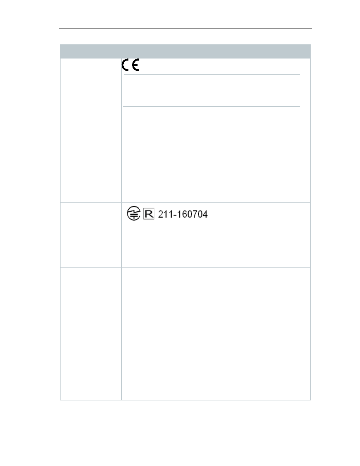
7 Authorizations
Japan Information
KCC Warning
Emirates
FCC Warnings
Country Comments
Europa + EFTA
Japan
EU countries:
Belgium (BE), Bulgaria (BG), Denmark (DK), Germany (DE),
Estonia (EE), Finland (FI), France (FR), Greece (GR), Ireland
(IE), Italy (IT), Latvia (LV), Lithuania (LT), Luxembourg (LU),
Malta (MT), Netherlands (NL), Austria (AT), Poland (PL),
Portugal (PT), Romania (RO), Sweden (SE), Slovakia (SK),
Slovenia (SI), Spain (ES), Czech Republic (CZ), Hungary
(HU), United Kingdom (GB), Republic of Cyprus (CY).
EFTA countries:
Iceland, Liechtenstein, Norway, Switzerland
South Africa ICASA
Radio Equipment Type Approval Number:
testo 160 IAQ: TA-2018/075
South Korea
testo 160 TH: R-CRM-te2-05722021
testo 160 THL: R-CRM-te2-05722024
testo 160 IAQ: R-CRM-te2-05722014
United Arab
Authorization Number: ER57487/17
USA Contains FCC ID: N8NLSD4WF0459
TH/E/THE/THL: FCC ID: WAF-0572202X
IAQ: FCC ID: WAF-05722014
54
Find Quality Products Online at: [email protected]
www.GlobalTestSupply.com
Page 55
Country Comments
Feature
Values
WLAN Range
100 m
WLAN type
LSD4WF0459-01D0
802.11b/g/n
Company
Lierda Technology Group co., LTD
RF Band
2412-2472MHz
Transmitter Power
13.42dBm
IC Warnings:
FCC Warnings:
For your own safety
FCC warning statement
Wi-Fi-Module
WLAN radio class Accord with the standard of IEEE
This instrument complies with Part 15C of the FCC Rules and
Industry Canada RSS-210 (revision 8). Commissioning is subject to
the following two conditions:
7 Authorizations
(1) This instrument must not cause any harmful interference and
(2) this instrument must be able to cope with interference, even if
this has undesirable effects on operation.
Cet appareil satisfait à la partie 15C des directives FCC et au standard
Industrie Canada RSS-210 (révision 8). Sa mise en service est soumise aux
deux conditions suivantes :
(1) cet appareil ne doit causer aucune interférence dangereuse et
(2) cet appareil doit supporter toute interférence, y compris des interférences
qui provoquerait des opérations indésirables.
Information from the FCC (Federal Communications Commission)
Shielded cables should be used for a composite interface. This is to ensure
continued protection against radio frequency interference.
This equipment has been tested and found to comply with the limits for a Class
C digital device, pursuant to Part 15 of the FCC Rules. These limits are
designed to provide reasonable protection against harmful interference in a
residential installation. This equipment generates, uses and can radiate radio
55
Find Quality Products Online at: [email protected]
www.GlobalTestSupply.com
Page 56
7 Authorizations
Caution
Warning
Japan Information:
frequency energy and, if not installed and used in accordance with the
instructions, may cause harmful interference to radio communications.
However, there is no guarantee that interference will not occur in a particular
installation. If this equipment does cause harmful interference to radio or
television reception, which can be determined by turning the equipment off and
on, the user is encouraged to try to correct the interference by one or more of
the following measures:
• Reorient or relocate the receiving antenna.
• Increase the separation between the equipment and receiver.
• Connect the equipment into an outlet on a circuit different from that to
which the receiver is connected.
• Consult the dealer or an experienced radio/TV technician for help.
Changes or modifications not expressly approved by the party responsible for
compliance could void the user's authority to operate the equipment. Shielded
interface cable must be used in order to comply with the emission limits.
This device complies with Part 15 of the FCC Rules.
Operation is subject to the following two conditions:
(1) this device may not cause harmful interference, and
(2) this device must accept any interference received,
including interference that may cause undesired operation.
当該機器には電波法に基づく、技術基準適合証明等を受けた特定無線設備を装
着している。
KCC Warning
해당 무선 설비는 운용 중 전파혼신 가능성이 있음.
56
Find Quality Products Online at: [email protected]
www.GlobalTestSupply.com
 Loading...