

Page 1
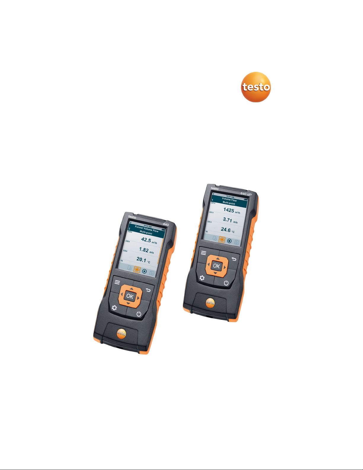
testo 440 – Climate Measuring Instrument
Instruction manual
Find Quality Products Online at: [email protected]
www.GlobalTestSupply.com
Page 2

Contents
1 Safety and disposal .................................................................................. 5
2 Authorisations and certification ................................................................ 7
3 Description of the instrument ................................................................... 7
4 Operation ............................................................................................... 15
1.1 About this document .............................................................................. 5
1.2 Security .................................................................................................. 5
1.3 Warning notices ..................................................................................... 6
1.4 Disposal ................................................................................................. 7
3.1 Use ......................................................................................................... 7
3.2 Overview of testo 440 ............................................................................ 8
3.3 Display overview .................................................................................... 9
3.4 Magnetic holder ................................................................................... 10
3.5 Power supply ....................................................................................... 11
3.6 Probe overview .................................................................................... 12
3.6.1 Compatible cable probes ...................................................... 12
3.6.2 Compatible Bluetooth® probes .............................................. 13
3.6.3 Compatible NTC probes ........................................................ 13
3.6.4 Compatible Smart Probes ..................................................... 14
3.6.5 Compatible Pt100 probes...................................................... 14
4.1 Commissioning .................................................................................... 15
4.2 Switching the testo 440 on/off ............................................................. 15
4.3 Making basic settings .......................................................................... 16
4.3.1 Establishing a Bluetooth® connection ................................... 17
4.3.2 Setting power options ........................................................... 17
4.3.3 Setting the ambient conditions .............................................. 19
4.3.4 Configuring the unit system ................................................... 19
4.3.5 Setting the date and time ...................................................... 20
4.3.6 Setting the language .............................................................. 21
4.3.7 Showing general device information ..................................... 21
4.3.8 Humidity adjustment.............................................................. 22
4.3.9 Resetting the instrument or probe to default settings ........... 23
4.4 Managing saved measurement data .................................................... 23
4.4.1 Printing .................................................................................. 26
Contents
Find Quality Products Online at: [email protected]
www.GlobalTestSupply.com
Page 3

Contents
5 Maintenance .......................................................................................... 49
6 Technical data ....................................................................................... 51
7 Tips and assistance ............................................................................... 53
4.4.2 CSV export ............................................................................ 27
4.5 Carrying out measurements ................................................................ 29
4.5.1 Connecting the cable probe with testo 440 .......................... 29
4.5.2 Connecting the Bluetooth® probe with testo 440 ................. 29
4.5.3 Basic View ............................................................................ 30
4.5.4 Selecting application menus ................................................. 32
4.5.5 Volume flow application [Volume Flow] ................................ 32
4.5.6 Funnel volume flow application [Funnel Volume Flow] ......... 34
4.5.7 Pitot volume flow application [Pitot Volume Flow] ................ 37
4.5.8 K-factor volume flow application [K-Factor Volume Flow] .... 38
4.5.9 Heating/cooling load application [Heating/Cooling Load] ..... 40
4.5.10 CO measurement application [CO Diagnostic] ..................... 42
4.5.11 Mould indication application [Mould Indication] ................... 44
4.5.12 Turbulence measurement application [Draught Rate] ........... 46
4.5.13 Performing long-term measurement application [Logger
Mode] .................................................................................... 47
5.1 Battery replacement ............................................................................ 49
5.2 Cleaning testo 440 ............................................................................... 49
5.3 Calibration ........................................................................................... 49
5.4 Carrying out a firmware update ........................................................... 50
7.1 Questions and answers ....................................................................... 53
7.1.1 LED status Bluetooth® probe ................................................ 53
7.1.2 Hot wire measurement not possible ..................................... 53
7.2 Accessories and spare parts ............................................................... 53
Find Quality Products Online at: [email protected]
www.GlobalTestSupply.com
Page 4

1 Safety and disposal
1.1 About this document
1.2 Security
General safety instructions
• The instruction manual is an integral part of the instrument.
• Pay particular attention to the safety instructions and warning advice in
order to prevent injury and damage to the product.
• Keep this documentation to hand so that you can refer to it when
necessary.
• Hand this instruction manual on to any subsequent users of the product.
• Only operate the product properly, for its intended purpose, and within the
parameters specified in the technical data.
• Do not apply any force.
• Do not operate the instrument if there are signs of damage on the housing,
mains unit or connected cables.
• Dangers may also arise from objects to be measured or the measuring
environment. Always comply with the locally valid safety regulations when
carrying out measurements.
• Do not store the product together with solvents.
• Do not use any desiccants.
• Only perform maintenance and repair work on this instrument that is
described in this documentation. Follow the prescribed steps exactly when
doing the work.
• Use only original spare parts from Testo.
• Maintenance work that is not described in this documentation must only be
carried out by trained service engineers.
• Temperature information given on probes/sensors relates only to the
measuring range of the sensor technology. Do not expose handles and feed
lines to temperatures in excess of 70 °C (158 °F), unless they are expressly
authorized for use at higher temperatures.
• Do not carry out any contact measurements on uninsulated, live parts.
1 Safety and disposal
5
Find Quality Products Online at: [email protected]
www.GlobalTestSupply.com
Page 5
Batteries
1.3 Warning notices
DANGER
Risk of death!
WARNING
Indicates
CAUTION
Indicates possible minor injury.
1 Safety and disposal
• Transport and store the instrument only in the associated packaging, in
order to prevent any damage to the sensor.
• Improper use of batteries may cause the batteries to be destroyed, or lead
to injury due to current surges, fire or escaping chemicals.
• Only use the batteries supplied in accordance with the instructions in the
instruction manual.
• Do not short-circuit the batteries.
• Do not take the batteries apart and do not modify them.
• Do not expose the batteries to heavy impacts, water, fire or temperatures in
excess of 60 °C.
• Do not store the batteries in the proximity of metal objects.
• Do not use any leaky or damaged batteries.
• Take the rechargeable battery out of the instrument immediately if it is not
functioning properly or if it shows signs of superheating. Rechargeable
battery may be hot!
• In the event of contact with battery acid: rinse affected areas thoroughly
with water, and if necessary consult a doctor.
• When not in use for a long period of time, take the rechargeable battery out
of the instrument to prevent exhaustive discharge.
Always pay attention to any information marked with the following warning
notices along with warning pictograms. Implement the specified precautionary
measures!
possible serious injury.
6
Find Quality Products Online at: [email protected]
www.GlobalTestSupply.com
Page 6

CAUTION
Indicates possible damage to equipment.
1.4 Disposal
2 Authorisations and certification
Approval and
Certification
3 Description of the instrument
3.1 Use
• Dispose of faulty rechargeable batteries and spent batteries in accordance
with the valid legal specifications.
• At the end of its useful life, deliver the product to the separate collection
point for electric and electronic devices (observe local regulations) or return
the product to Testo for disposal.
Please find the current country approvals in the attached
document.
2 Authorisations and certification
The testo 440 is used for measuring climate-related parameters. The testo 440
is particularly suitable for comfort level measurements for the workplace
evaluation and disturbance measurements in and at air conditioning systems.
The instrument is only to be used by qualified expert personnel.
Then product must not be used in potentially explosive atmospheres!
7
Find Quality Products Online at: [email protected]
www.GlobalTestSupply.com
Page 7
3 Description of the instrument
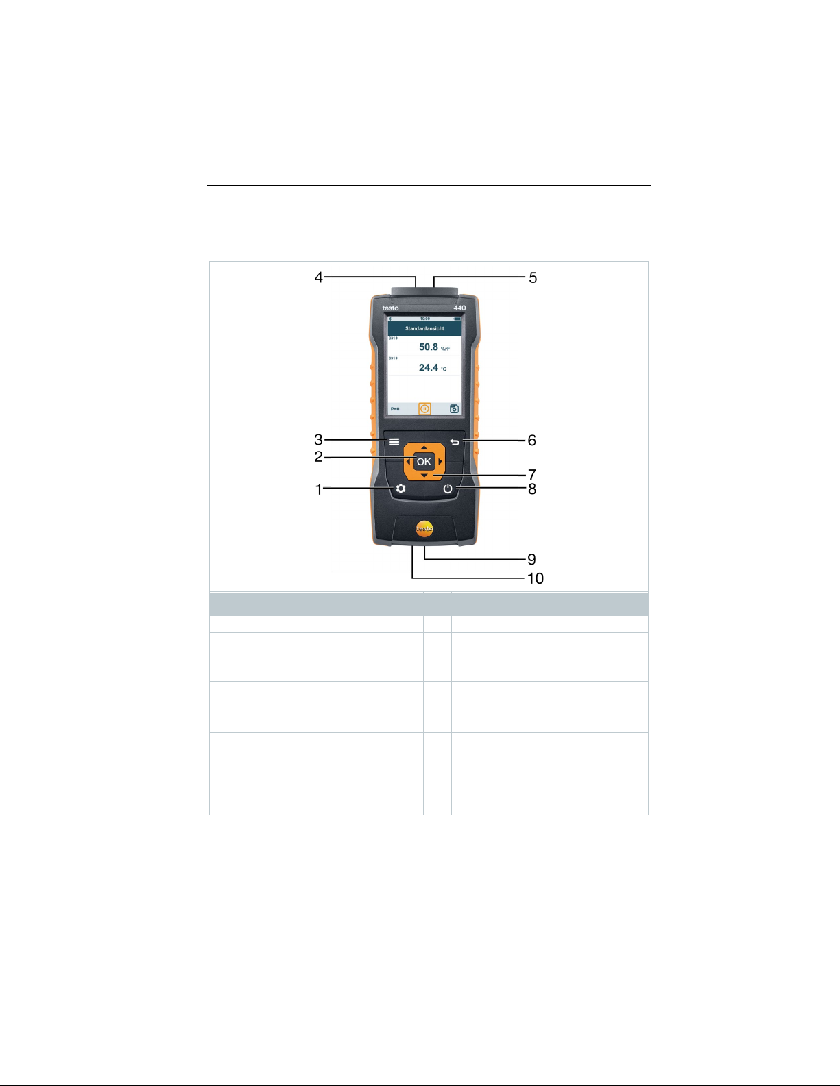
3.2 Overview of testo 440
1
Settings
2
Confirm input/selection
3
4
5
connection
6
7
8
9
10
Element Element
Menu
Testo Universal Connector (TUC)
for connection of cabled probes
with corresponding plug
Type K thermocouple
Navigation
Micro USB port for data
transfers or connection to
external power supply
Back
Instrument ON/OFF
Connections for differential
pressure measurements
(+ / - labelling on rear of
instrument, only testo 440 dP)
8
Find Quality Products Online at: [email protected]
www.GlobalTestSupply.com
Page 8
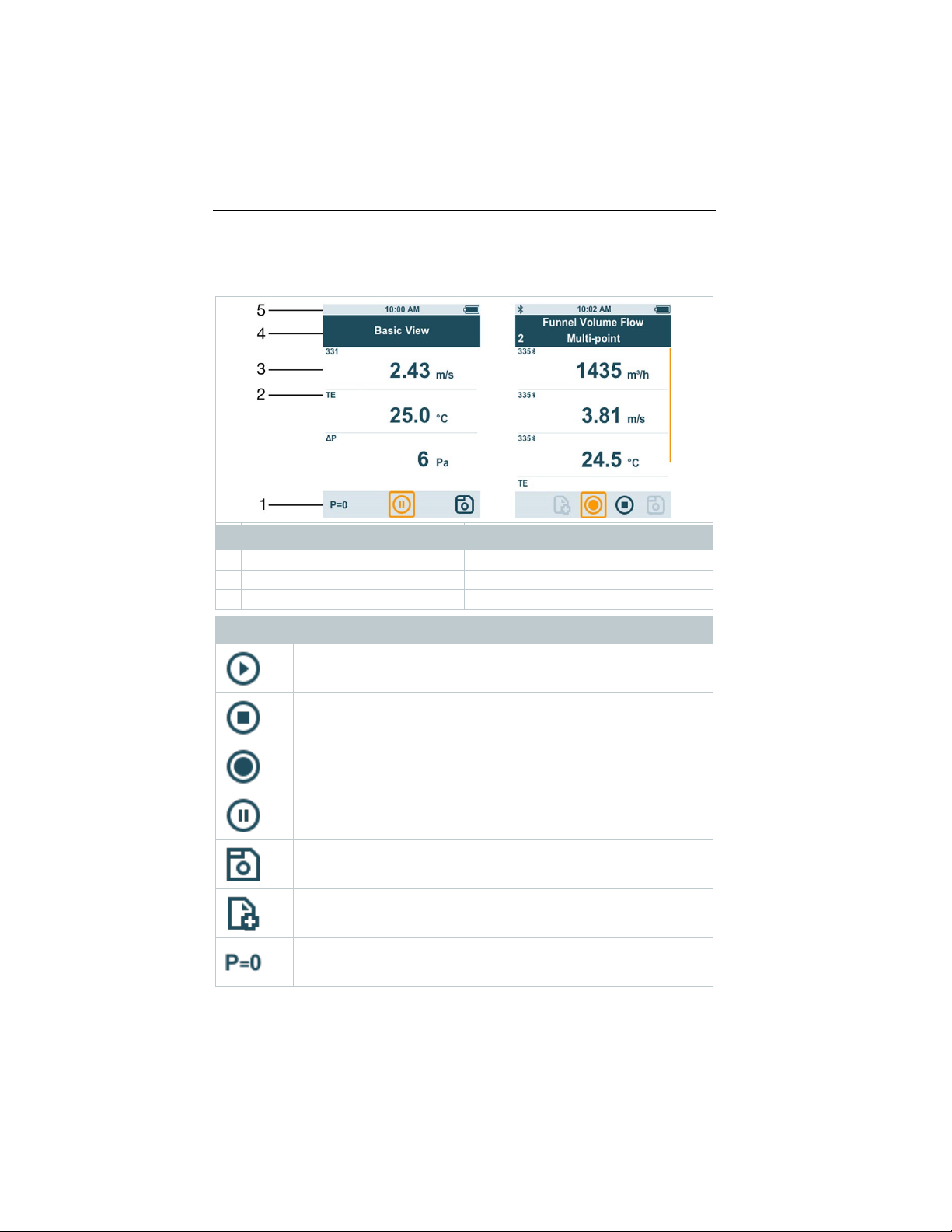
3.3 Display overview
1
2
3
4
5
Status bar
Element Element
Check line
Measuring values
Symbol Meaning
3 Description of the instrument
Probe identification
Header
Start measurement
Stop measurement
Carry out multi-point measurement
Pause measurement
Save measurement
New measurement
Zero pressure sensor
9
Find Quality Products Online at: [email protected]
www.GlobalTestSupply.com
Page 9
3 Description of the instrument
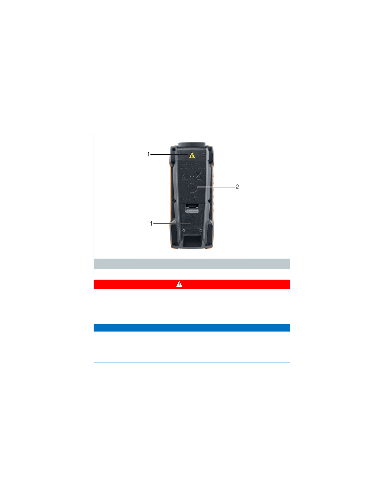
3.4 Magnetic holder
1
Integrated magnet
2
Battery compartment
DANGER
Integrated magnet
Danger to life for persons with pacemakers!
CAUTION
Integrated magnet
Damage to other devices!
Two magnets are integrated in the testo 440 measuring instrument. These can
be used as a holder on magnetic surfaces.
Element Element
- Keep a distance of at least 20 cm between your pacemaker and the
measuring instrument.
- Keep a safe distance from devices that may be damaged by magnetism
(e.g. monitors, computers, credit cards, memory cards, etc.).
10
Find Quality Products Online at: [email protected]
www.GlobalTestSupply.com
Page 10
3.5 Power supply
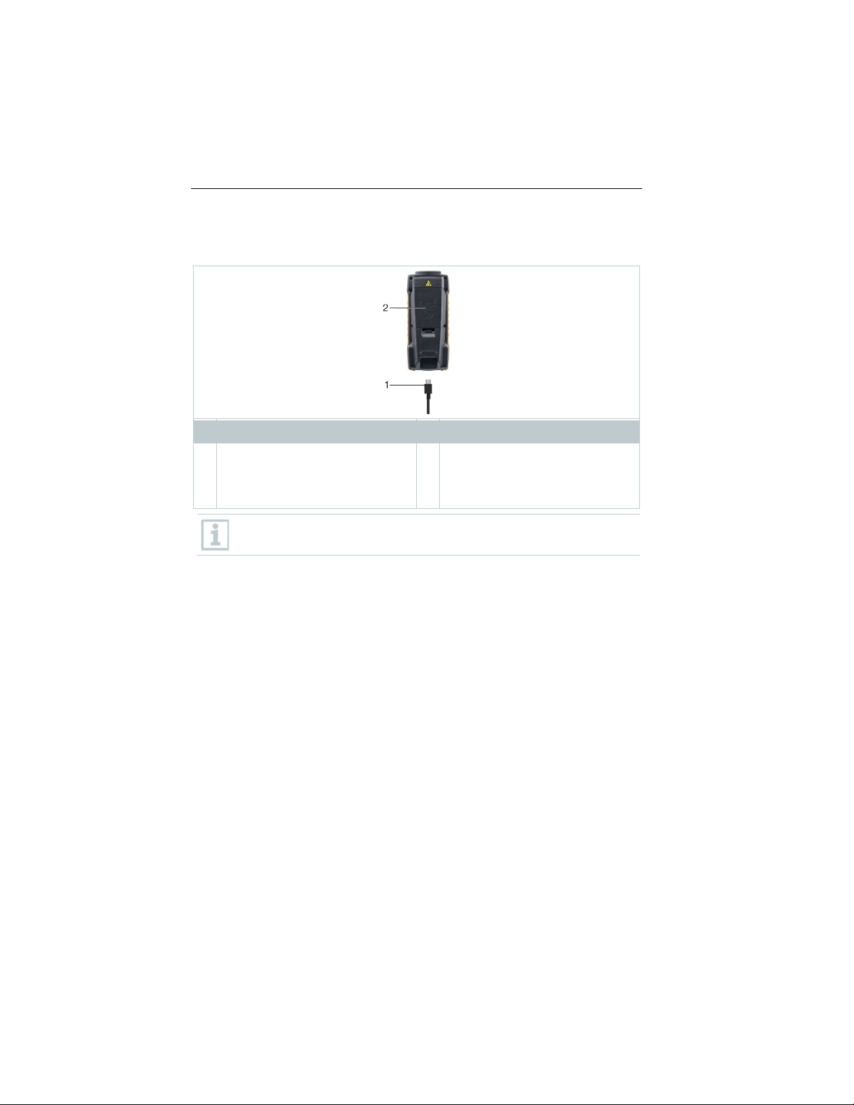
1
2
Element Element
Mains connection via micro USB
cable (must be connected to the
power source). No batteries are
required for operation
3 Description of the instrument
Battery compartment - 3 x AA
batteries
When connected to a power supply, the rechargeable batteries used
will not be recharged.
11
Find Quality Products Online at: [email protected]
www.GlobalTestSupply.com
Page 11
3 Description of the instrument
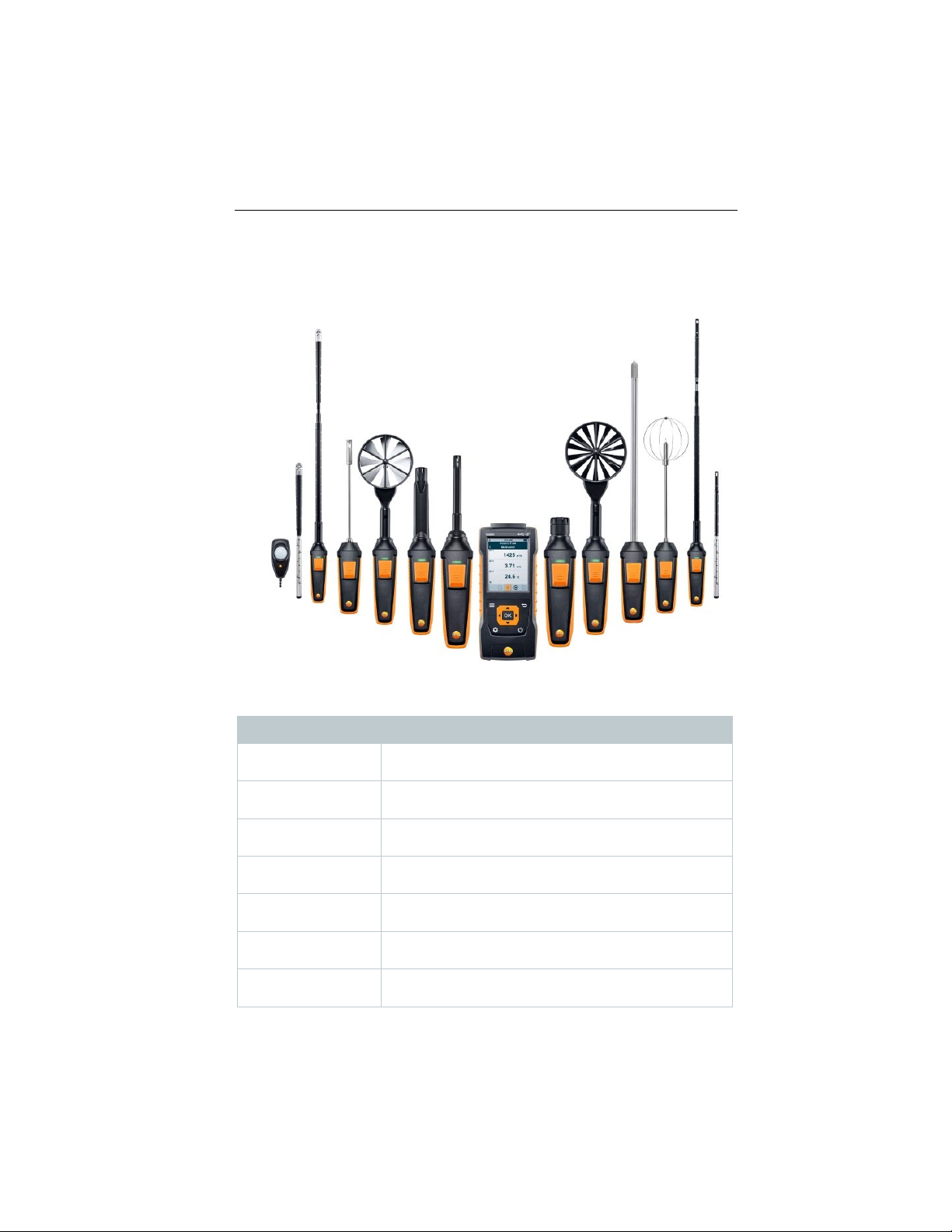
3.6 Probe overview
3.6.1 Compatible cable probes
sensor, fixed cable
sensor, fixed cable
sensor, fixed cable
fixed cable
fixed cable
Order number Name
0635 1032 Hot wire probe including temperature sensor, fixed
0635 1572 Hot wire probe including temperature and humidity
0635 1026 Hot wire probe (Ø 7.5 mm) including temperature
0635 1051 Hot wire probe (Ø 3 mm) including temperature
0635 9572 Vane probe (Ø 16 mm) including temperature sensor,
0635 9372 High-precision vane probe (Ø 100 mm) including
0635 9432 Vane probe (Ø 100 mm) including temperature sensor,
12
cable
temperature sensor, fixed cable
Find Quality Products Online at: [email protected]
www.GlobalTestSupply.com
Page 12

3 Description of the instrument
up to +180 °C, fixed cable
0635 0551
Lux probe
0632 1272
CO probe, fixed cable
0628 0152
Turbulence probe, fixed cable
0635 9532
Vane probe (Ø 16 mm) fixed cable
0635 1052
Fume cupboard probe, fixed cable
3.6.2 Compatible Bluetooth® probes
and humidity sensor
temperature sensor
temperature sensor
Bluetooth®, including temperature sensor
0636 9731
Temperature-humidity probe with Bluetooth®
3.6.3 Compatible NTC probes
temperature sensor
0615 1712
Robust air probe – with NTC temperature sensor
Order number Name
0636 9772 High-precision temperature-humidity probe, fixed
cable
0636 9775 Robust temperature-humidity probe for temperatures
0636 9732 Temperature-humidity probe, fixed cable
0632 1552 CO2 probe including temperature and humidity
sensor, fixed cable
Order number Name
0635 1571 Hot wire probe with Bluetooth®, including temperature
0635 9571 Vane probe (Ø 16 mm) with Bluetooth®, including
0635 9431 Vane probe (Ø 100 mm) with Bluetooth®, including
0635 9371 High-precision vane probe (Ø 100 mm) with
0636 9771 High-precision temperature-humidity probe with
Bluetooth
0632 1551 CO2 probe with Bluetooth®, including temperature
and humidity sensor
0632 1271 CO probe with Bluetooth®
Order number Name
0615 1212 Waterproof immersion/penetration probe – with NTC
®
13
Find Quality Products Online at: [email protected]
www.GlobalTestSupply.com
Page 13

3 Description of the instrument
measurements on pipes (Ø 6-35 mm)
measurements on pipes (Ø 5-65 mm)
3.6.4 Compatible Smart Probes
smartphone
smartphone
smartphone
operated by smartphone
3.6.5 Compatible Pt100 probes
0618 0275
High-precision digital Pt100 penetration probe
0618 0073
Digital Pt100 penetration probe
0618 0071
Flexible digital Pt100 temperature probe
Order number Name
0615 4611 Temperature probe with Velcro and NTC temperature
sensor
0615 5505 Clamp probe with NTC temperature sensor – for
0615 5605 Pipe wrap probe with NTC temperature sensor – for
Order number Name
0560 1115 testo 115i - clamp thermometer operated by
smartphone
0560 1805 testo 805i - infrared thermometer operated by
smartphone
0560 1605 testo 605i - thermohygrometer operated by
0560 1405 testo 405i - thermal anemometer operated by
0560 1410 testo 410i - vane anemometer operated by
0560 1510 testo 510i - differential pressure measuring instrument
0560 1549 testo 549i - high-pressure measuring instrument
operated by smartphone
0560 1915 testo 915i - thermometer operated by smartphone
Order number Designation
0618 7072 Glass-coated digital Pt100 laboratory probe
0618 0072 Robust, fast-reaction, digital Pt100 air probe
14
Find Quality Products Online at: [email protected]
www.GlobalTestSupply.com
Page 14
4 Operation
4.1 Commissioning
1
Open the battery compartment cover.
2
3
Close the battery compartment cover.
4.2 Switching the testo 440 on/off
Initial activation
Initial Operation
The testo 440 is supplied with inserted batteries. The batteries are
secured by a battery safety strip.
Remove the battery safety strip.
The testo 440 is ready for use.
4 Operation
For initial commissioning or after a factory reset, the
menu is opened automatically. In normal mode, the last menu used is
displayed after switching it on.
15
Find Quality Products Online at: [email protected]
www.GlobalTestSupply.com
Page 15

4 Operation
1
Initial Operation
2
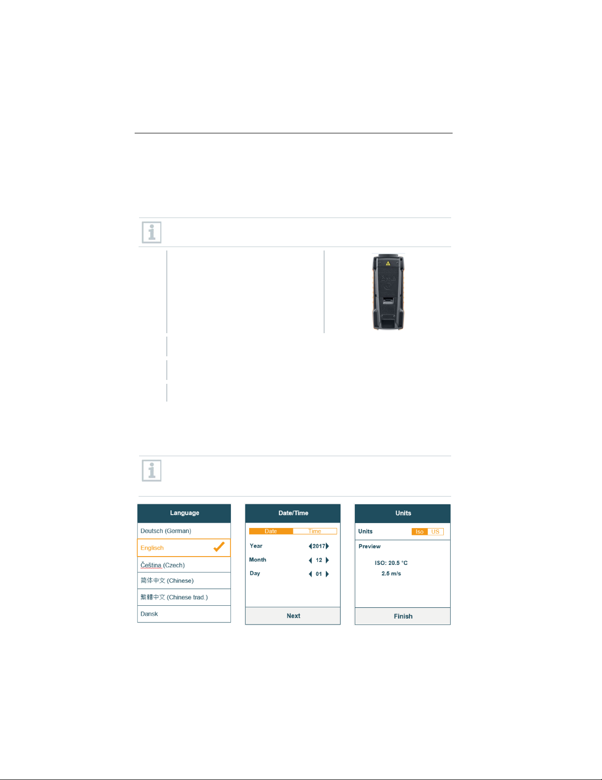
Make the following settings in sequence:
[Language]
[Date/Time]
-
[Units]
Switching on
1
Switching off
1
4.3 Making basic settings
Basic View
Show current measuring values
Memory
Show and manage saved measurements
Press .
The
menu is displayed.
- Language
Date (year/month/day) and time (format, time)
Unit system (ISO/US)
The basic settings have been set. They can be adjusted any time in
Settings.
Press .
The last active menu when the instrument was switched off is
displayed.
Press and for at least 3 seconds.
The testo 440 switches itself off.
Use the menu key to go to the testo 440 Settings menu. The following settings
are available in this menu:
Menu item Function/Settings
Select Application Select required application for the
measurement
16
Find Quality Products Online at: [email protected]
www.GlobalTestSupply.com
Page 16
Menu item Function/Settings
4.3.1 Establishing a Bluetooth® connection
testo 440 is switched on.
1
You are in the Settings menu.
1
Bluetooth
2
Bluetooth
3
4.3.2 Setting power options
Settings Making basic settings:
- Bluetooth
- Power Management Ambient Conditions
- Units
- Date/time
- Languages
- General (instrument and probe status,
reset)
Press and at the same time for at least 3 seconds.
Bluetooth® is activated or deactivated and either appears or
or
disappears from the display.
4 Operation
Use to select
Use to enable
Bluetooth® is activated or deactivated and either appears or
disappears from the display.
Press or to exit the menu.
You can manage the energy consumption for your testo 440. The following
functions are available for this purpose:
• Auto Off: testo 440 switches off automatically after 5 minutes of inactivity
.
.
17
Find Quality Products Online at: [email protected]
www.GlobalTestSupply.com
Page 17
4 Operation
You are in the Settings menu.
1
Power Management
2
3
If the testo 440 is in logger mode, the Auto Off function is automatically
4
Setting Auto Off
You are in the Power Management menu.
1
Auto Off
2
Off
3
Setting power saving
You are in the Power Management menu.
1
Power Saving
2
Off
• Power Saving: the screen brightness is reduced to 10% after a minute; the
set brightness is restored by pressing the button
• Brightness: setting the screen brightness from 10% to 100%
Use to select
.
Press or on the navigation key.
Use to select the required setting and make changes.
If the Auto Off function is enabled, the testo 440 automatically
switches itself off after 5 minutes of inactivity.
deactivated during an active measurement.
Press or to exit the menu.
Use to select
Use to switch the On or
.
function on or off.
Press or to exit the menu.
Use to select
Use to switch the On or
.
function on or off.
18
Find Quality Products Online at: [email protected]
www.GlobalTestSupply.com
Page 18
4 Operation
3
Setting brightness
You are in the Power Management menu.
1
Brightness
2
3
4.3.3 Setting the ambient conditions
Ambient Conditions
You are in the Settings menu.
1
Ambient Conditions
2
3
4
5
4.3.4 Configuring the unit system
Units
Press or to exit the menu.
Use to select
Use to set the brightness.
Press or to exit the menu.
In the
menu, you can configure the following parameters:
• Ambient Pressure
Pressure unit: Pa/mbar/hPa/mmH2O/inH2O/Torr/inHg/kPa/psi
• Ambient temperature
Unit of temperature: °C/°F
Use to select
Press or on the navigation key.
Use to select the parameters to be modified.
.
.
Use to configure the parameters to be modified.
Press or to exit the menu.
In the
menu, you can switch between the European ISO and American
US unit system.
19
Find Quality Products Online at: [email protected]
www.GlobalTestSupply.com
Page 19
4 Operation
You are in the Settings menu.
1
ISO/US
m/s
fpm
m3/h
cfm
°C
°F
2
3
4.3.5 Setting the date and time
Date/Time
You are in the Settings menu.
1
Date/Time
2
3
4
Use to select the
The following units are used depending on what has been selected:
.
ISO unit US unit
wb °C wb °C
dp °C dp °F
Use to select the required setting.
Press or to exit the menu.
When the unit system is changed, the units specified in the Basic View
are overwritten.
You can set the date and time in the
the formats 24 h, PM and AM.
menu. You can set the time in
Use to select the
Press or on the navigation key.
.
Use to select the required settings.
Press or to exit the menu.
20
Find Quality Products Online at: [email protected]
www.GlobalTestSupply.com
Page 20
4 Operation
4.3.6 Setting the language
You are in the Settings menu.
4
Language
5
6
Language
7
4.3.7 Showing general device information
General
You are in the Settings menu.
1
General
2
-
Use to select
.
Press or on the navigation key.
Use to select the required
Confirm by clicking .
Under the
testo 440 and connected probes.
settings.
The following information can be viewed:
About Device
About Probe (visible once
probe is connected)
Exit from the menu is automatic and the language is applied.
When the unit system is changed, the units specified in the Basic View
are overwritten.
menu item, you will find all of the information about the
You can also reset the instrument to default
Use to select
.
Press or on the navigation key.
Name
- Serial Number
- Firmware Version
- Battery
- Memory
- Probe Name
- Serial Number
- Firmware Version
- Battery
.
21
Find Quality Products Online at: [email protected]
www.GlobalTestSupply.com
Page 21
4 Operation
4.3.8 Humidity adjustment
0636 9731
Temperature-humidity probe with Bluetooth®
0636 9732
Temperature-humidity probe, fixed cable
to +180 °C, fixed cable
Adjustment time for humidity probe: at least 30 minutes.
Humidity Adjustment
1
Select the relevant reference point of 11.3 or 75.3% RH with .
2
Select the probe to be adjusted.
3
Adjust
Adjustment successful!
Humidity Adjustment
For humidity adjustment, the measurement parameter of the connected probe
is adjusted to the reference value at the two standard adjustment points 11.3%
RH and 75.3% RH; any deviations between the measuring value and the
nominal value are minimised across the entire measuring range.
The Testo calibration set provides a reference value to calculate the offset for a
humidity adjustment.
Humidity adjustment is possible with the following probes:
Order number Name
0636 9771 High-precision temperature-humidity probe with
0636 9772 High-precision temperature-humidity probe, fixed cable
0636 9775 Robust temperature-humidity probe for temperatures up
testo 440 is switched on and the corresponding probe is connected.
Probe is already exposed to reference conditions (e.g. salt pot) for an
adequate adjustment time.
See Section 3.3.8
Bluetooth
®
22
You are in the
Use to select
and confirm with .
menu.
An information window displays the remaining adjustment time and
the adjustment is carried out.
An information window displays the text
.
Find Quality Products Online at: [email protected]
www.GlobalTestSupply.com
Page 22
4 Operation
4
the calibration data
4.3.9 Resetting the instrument or probe to default settings
You are in the Settings menu.
4
General
5
6
Use to select Reset Device or Reset Probe.
7
8
Confirm
9
4.4 Managing saved measurement data
Memory [Memory]
Press or to exit the menu.
After performance of a probe reset, the probe uses
set by the factory.
Use to select
Press or on the navigation key.
.
Press .
Use to select
.
Press or on the navigation key.
When the instrument is restarted, it will be reset to default settings.
In the
menu item, all measurements from the application
menu are saved with the time and date.
Measurements are saved in the last folder set up. If there is no folder available,
one will automatically be set up. Every day, a new folder is automatically set up
on the measuring instrument.
23
Find Quality Products Online at: [email protected]
www.GlobalTestSupply.com
Page 23
4 Operation
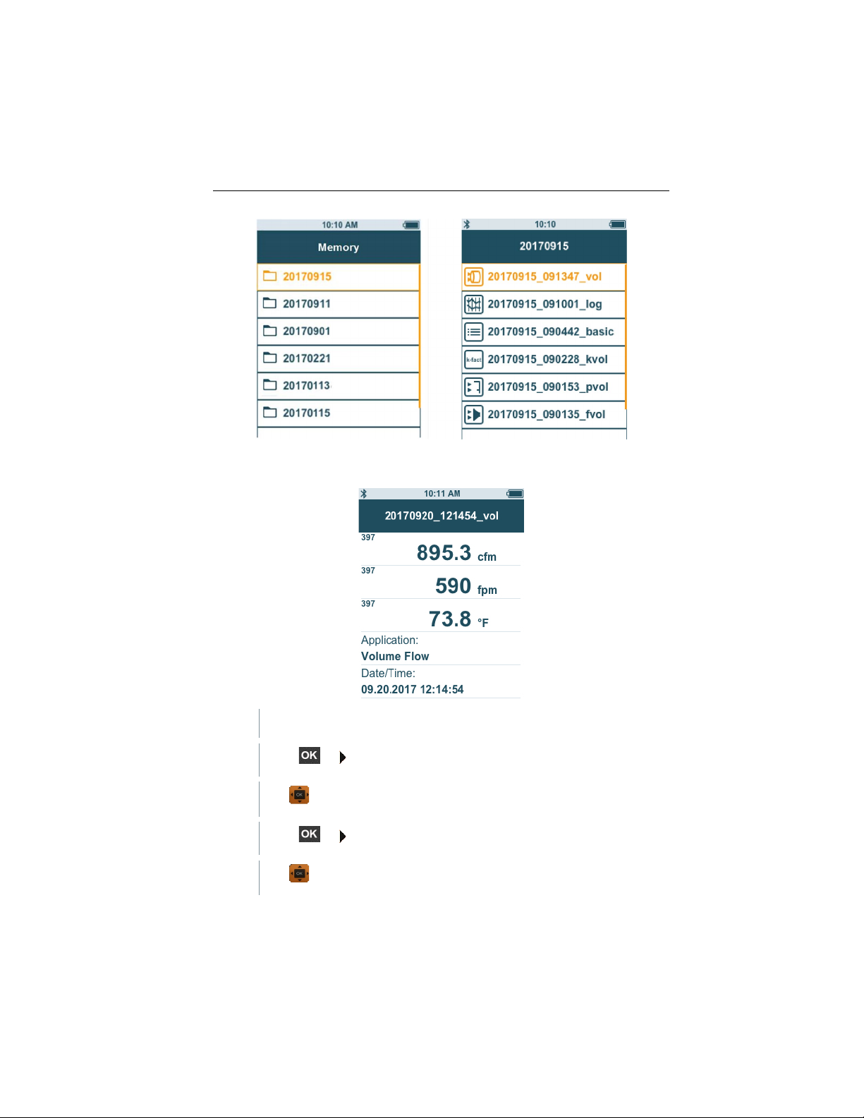
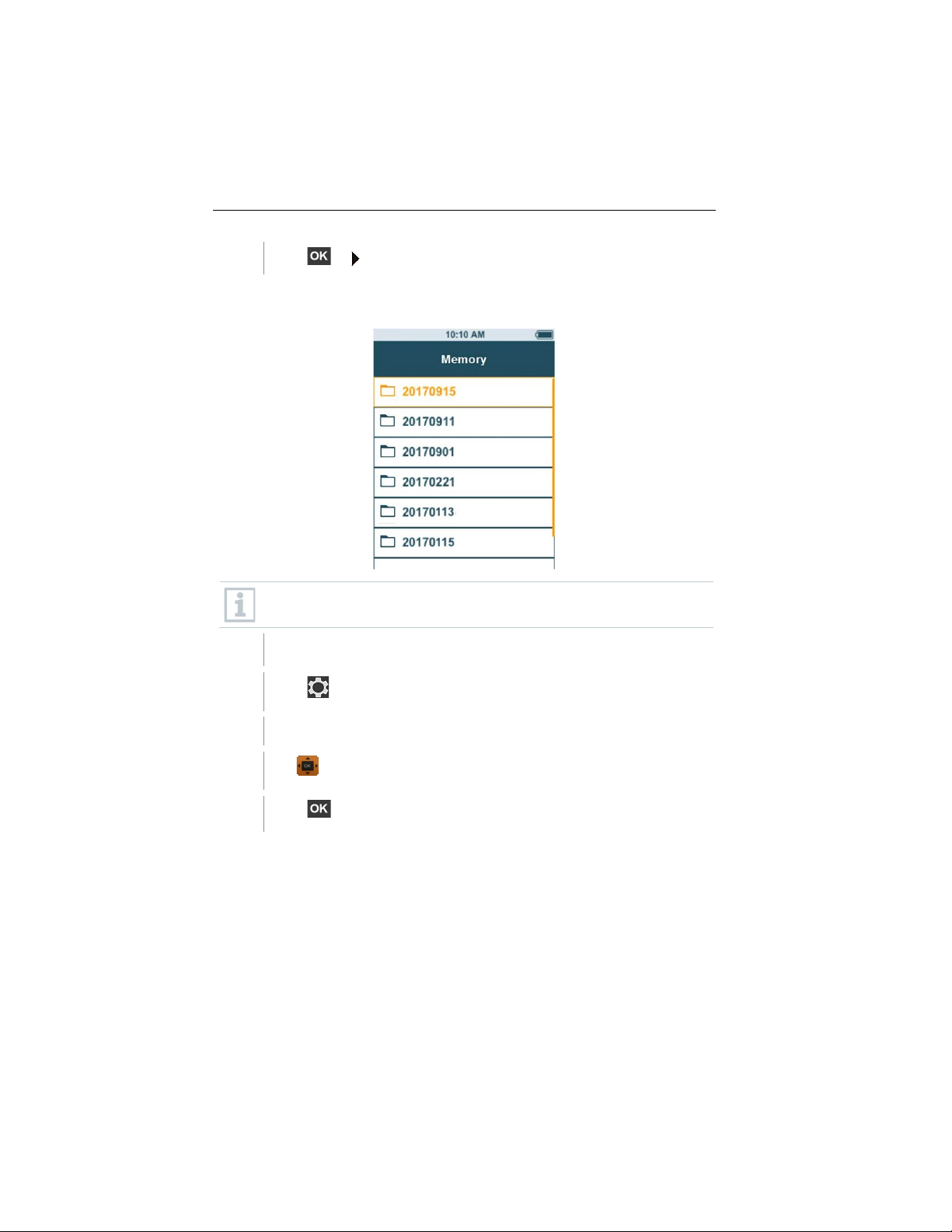
Showing saved measurements
You are in the Memory menu [Memory].
3
4
5
6
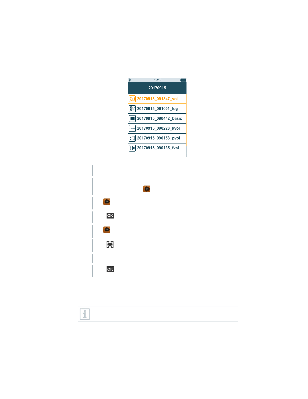
This function can be used to retrieve saved measurement results.
Press or on the navigation key.
Use to select the required folder.
Press or on the navigation key.
Use to select the required measurement.
24
Find Quality Products Online at: [email protected]
www.GlobalTestSupply.com
Page 24
7
Press or on the navigation key to display measurement results.
Creating and deleting folders
You are in the Memory menu [Memory].
1
2
Create Folder
Delete Folder
3
Deleting saved measurement data
This function can be used to create and delete folders for your measurements.
4 Operation
If you delete a folder, you will also delete the measurements it
contains.
Press in the folder view.
The drop-down menu is displayed.
Use to select either
Press .
This function can be used to delete saved measurements.
or
.
25
Find Quality Products Online at: [email protected]
www.GlobalTestSupply.com
Page 25
4 Operation
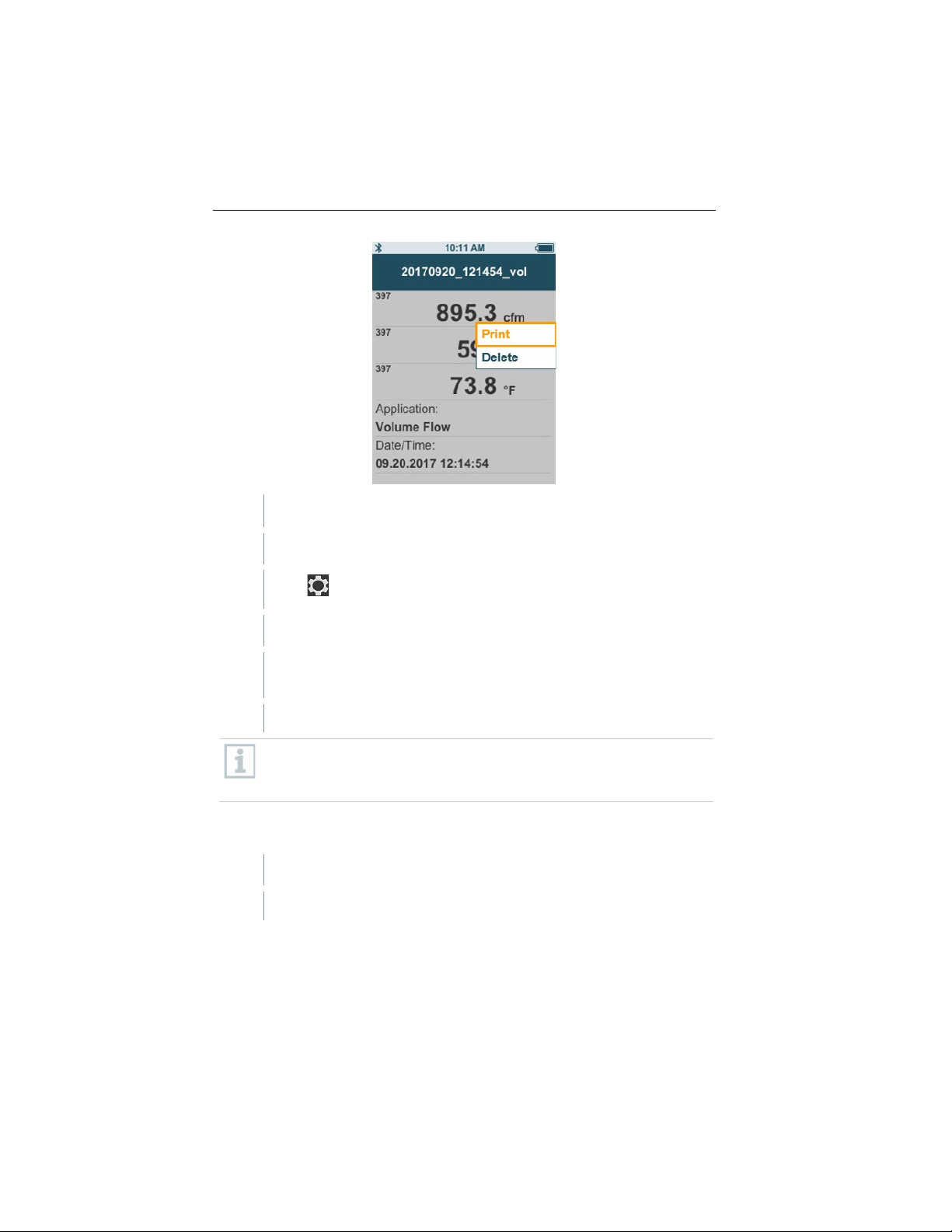
You are in the Memory menu.
a measurement file with .
1
2
3
4
5
4.4.1 Printing
You have selected a folder containing measurement data or selected
Use to select the required folder.
Press .
Use to select the required measurement.
Press .
The drop-down menu is displayed.
Press to delete the selected measurement data.
You can print out your measurement protocols directly on site using the
®
Bluetooth
printer (order no. 0554 0621).
Please refer to the relevant instruction manual for details on operating
the printer.
26
Find Quality Products Online at: [email protected]
www.GlobalTestSupply.com
Page 26
4 Operation
The Bluetooth® printer is connected to the testo 440.
1
Select the required measurement in the memory.
2
3
Select Print [Print].
4.4.2 CSV export
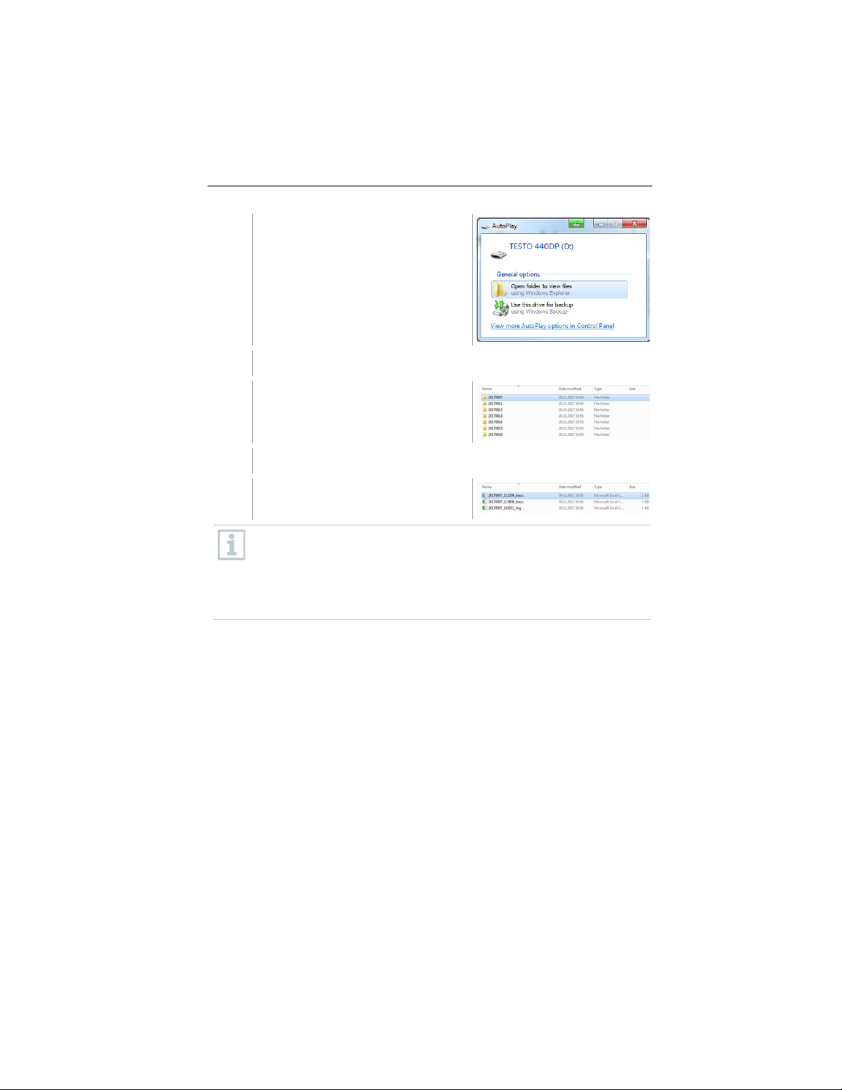
1
Connect the testo 440 to your computer using the micro USB cable.
AutoPlay
Press .
The Bluetooth® connection to the printer is automatically established.
This process may take a few seconds.
The protocol is printed.
®
During printing, the testo 440 interrupts the Bluetooth
the connected probe. The connection is automatically restored after
connection to
printing has finished.
The
window opens automatically on your screen.
27
Find Quality Products Online at: [email protected]
www.GlobalTestSupply.com
Page 27
4 Operation
2
Open folder to view files
[Open folder to view files]
3
4
target folder on your computer.
Click on
.
You can add other details about the project to the CSV file.
The window with available file folders opens.
Click on the required folder.
The window with available files opens.
Drag the file from the folder to the
If your file format is not displayed correctly, this is probably because
the language version of your operating system and your device are
different.
In this case, please open Excel and the relevant measurement data
document on the testo 440 from within Excel. A corresponding Excel
wizard enables modification of the file format.
28
Find Quality Products Online at: [email protected]
www.GlobalTestSupply.com
Page 28
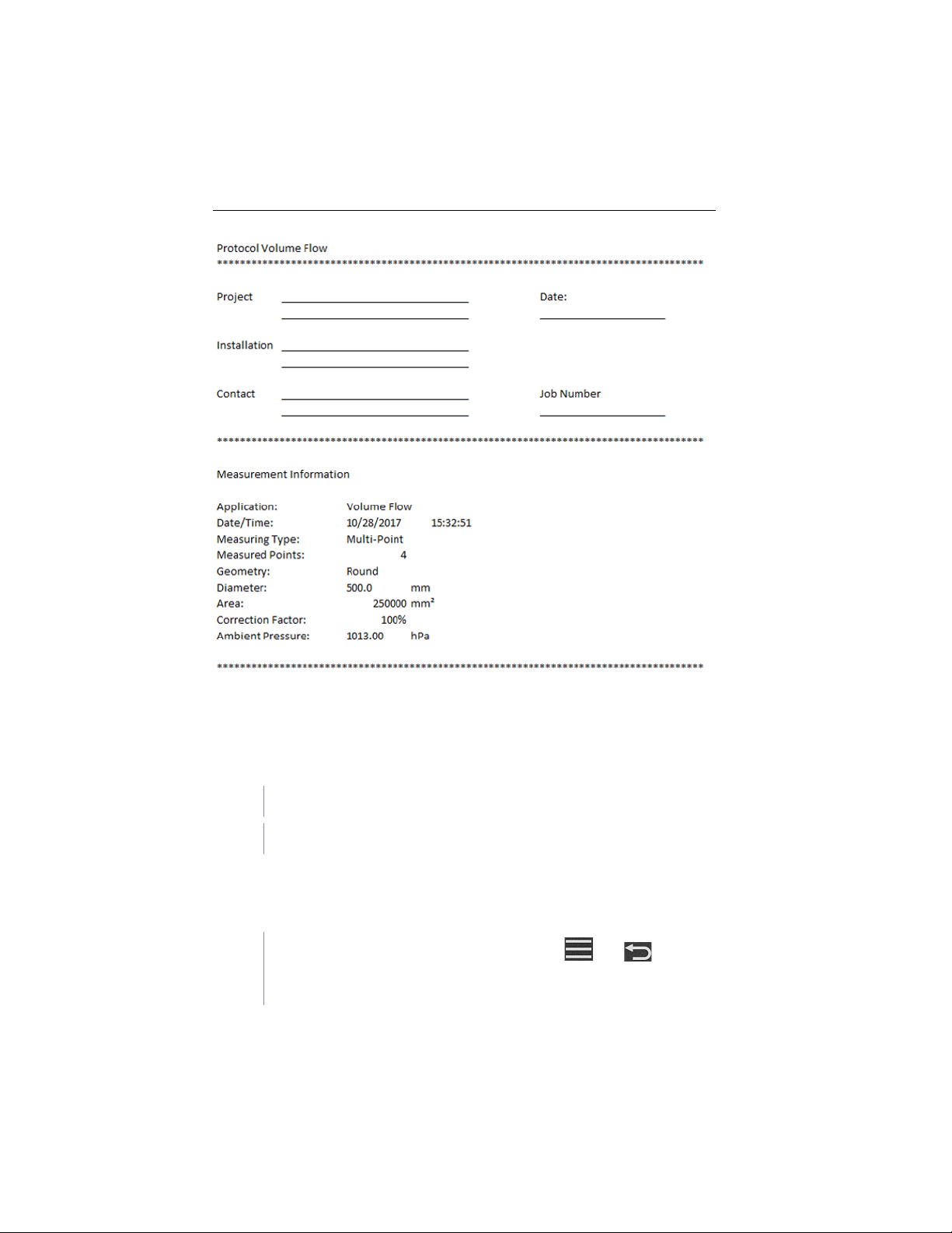
4 Operation
4.5 Carrying out measurements
4.5.1 Connecting the cable probe with testo 440
1
2
4.5.2 Connecting the Bluetooth® probe with testo 440
1
Settings
Connect the testo 440 to the probe using the TUC slot.
Remove the connector from the instrument to disconnect it.
Activate Bluetooth® using fast activation (press and at the
same time for a minimum of 3 seconds) or the
Section 3.3.1).
menu (see
29
Find Quality Products Online at: [email protected]
www.GlobalTestSupply.com
Page 29
4 Operation
connected to the
2
Press the button on the probe handle.
3
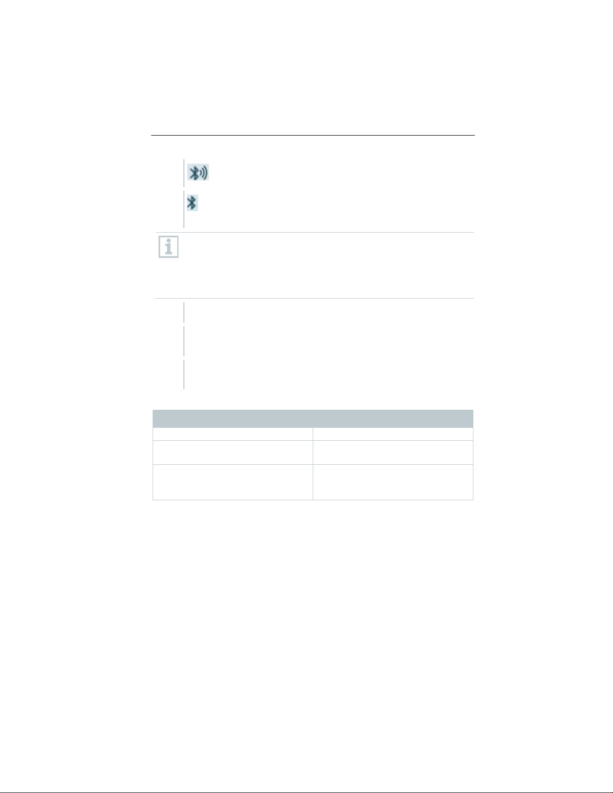
LED status
Flashing red
Low battery status
440.
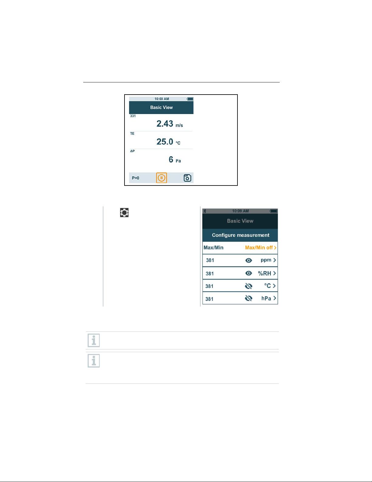
4.5.3 Basic View
Basic View [Basic View]
maximum
is shown top left on the display, as soon as the probe and testo
is displayed.
440 are connected to each other.
A connection to compatible Bluetooth® probes is automatically
searched for and established. Only one probe can be
testo 440 by Bluetooth®.
Please observe the relevant instructions for the probe when
commissioning it.
The LED on the handle flashes yellow. The LED flashes green while
the connection is being established.
Press the button on the probe handle a minimum of 3 seconds to
switch the probe off.
LED status Description
Flashing yellow Probe is switched on and searching
®
for the Bluetooth
connection.
Flashing green The probe is switched on and
connected via Bluetooth
®
to the testo
In the
, both current and minimum and maximum
measuring values can be read and saved. All compatible probes can be used.
For a list of all compatible probes see Section 2.6.
The
of following probes can be connected at the same time:
• 1x TC
®
• 1x Bluetooth
• 1x cable probe
probe
30
Find Quality Products Online at: [email protected]
www.GlobalTestSupply.com
Page 30
4 Operation
1
Configuration
menu [Configure measurement]
Depending on the connected probe, parameters can be configured for the
measurement, for example, visibility of individual values or units.
Press to open the
.
Individual values being hidden does not affect the application, only the Basic
View and long-term measurement. The configured units, on the other hand, are
also taken up in the application menus.
For the instrument model testo 440 dP, zeroing can also be
undertaken in the Basic View.
The accuracy specification applies immediately after zeroing of the
sensor. The sensor is affected by changes in position or attachment to
magnetic surfaces. Therefore, zero the sensor only in the instrument
end position.
31
Find Quality Products Online at: [email protected]
www.GlobalTestSupply.com
Page 31
4 Operation
4.5.4 Selecting application menus
Basic View
4.5.5 Volume flow application
cable
and humidity sensor
sensor, fixed cable
sensor, fixed cable
temperature sensor
The testo 440 has permanently installed application menus. These enable the
user to carry out convenient configuration and implementation of specific
measuring tasks.
Available application menus are enabled as soon as a probe is
connected. Unavailable application menus are greyed out on the
display. More than one probe has to be connected to make some
application menus accessible.
The units for the measuring values depend on the ISO/US setting and
configuration in the
Use this application to measure the volume flow at the outlet or in a ventilation
system duct. There are different options for this. These mainly differ in the
measuring range and require corresponding probes:
• Thermal probes (including temperature measurement and possibly humidity
measurement) for low flow velocities
• 16 mm wheel measuring head (including temperature measurement) for
average flow velocities
• Pitot tube for measurements at high velocities and in heavily contaminated
flows with a high particle content
This application menu is accessed by one of the following probes:
.
[Volume Flow]
Order number Name
0635 1032 Hot wire probe including temperature sensor, fixed
0635 1571 Hot wire probe with Bluetooth®, including temperature
0635 1572 Hot wire probe with Bluetooth®, including temperature
and humidity sensor
0635 1026 Hot wire probe (Ø 7.5 mm), including temperature
0635 1051 Hot wire probe (Ø 3 mm), including temperature
0635 9571 Vane probe (Ø 16 mm) with Bluetooth®, including
32
Find Quality Products Online at: [email protected]
www.GlobalTestSupply.com
Page 32
4 Operation
Bluetooth®, including temperature sensor
temperature sensor, fixed cable
temperature sensor
fixed cable
0635 1052
Fume cupboard probe, fixed cable
smartphone
A maximum of 1 Bluetooth® probe and one cable probe can be
Preparing for measurement
1
-
Order number Name
0635 9572 Vane probe (Ø 16 mm) including temperature sensor,
fixed cable
0635 9371 High-precision vane probe (Ø 100 mm) with
0635 9372 High-precision vane probe (Ø 100 mm) including
0635 9431 Vane probe (Ø 100 mm) with Bluetooth®, including
0635 9432 Vane probe (Ø 100 mm) including temperature sensor,
0560 1405 testo 405i - thermal anemometer operated by
0560 1410 testo 410i - vane anemometer operated by
connected. If two flow probes are connected, the cable probe is used
for the volume flow measurement.
smartphone
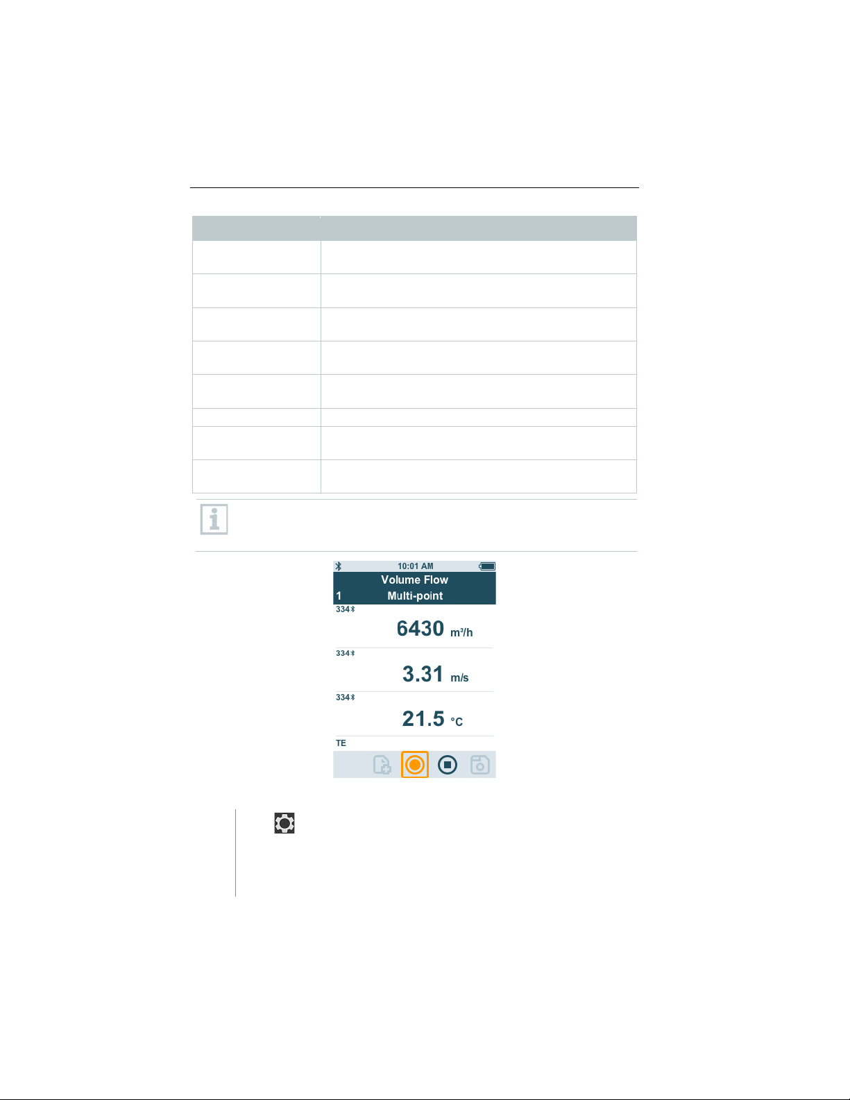
Press to configure the measurement.
You can set the following parameters:
Geometry: round, rectangular, area
33
Find Quality Products Online at: [email protected]
www.GlobalTestSupply.com
Page 33
4 Operation
- Measuring Type: multi-point/timed avg.
2
Use to select the required parameter and make settings.
3
Carrying out the measurement
A suitable probe is connected to the testo 440.
1
Remove the protective cap from the probe head.
2
Move the probe into the flow.
3
4
5
Carry out the measurement and save the measuring values.
4.5.6 Funnel volume flow application
- Volume Flow Unit: m3/h, cfm, l/s, m3/s
- Correction Factor: 1% to 200%
In a multi-point measurement, a mean value is calculated from the
individual measuring values.
In a timed average measurement, a mean value is calculated over a
certain period.
Several points can be measured. This generates a timed
average/multi-point total mean value.
Press or to exit the menu.
For measurements in flows with a known direction, the arrow mark on
the probe head must point in the direction of flow.
Align the probe with the assumed flow axis.
Read off the readings.
Low flow velocities may result in greater measurement uncertainty
during temperature and humidity measurement.
[Funnel
Volume Flow]
A volume flow rate funnel is required to determine the flow rate on ventilation
systems. The measurement can be carried out with a compatible vane probe in
34
Find Quality Products Online at: [email protected]
www.GlobalTestSupply.com
Page 34

4 Operation
and humidity sensor
sensor, fixed cable
temperature sensor
fixed cable
temperature sensor, fixed cable
temperature sensor
fixed cable
0635 1052
Fume cupboard probe, fixed cable
smartphone
connected. If two flow probes are connected, a cable probe is used for
conjunction with a funnel set. Alternatively, a thermal anemometer can also be
used in conjunction with a funnel.
The funnels differ in size. When selecting the funnel, make sure that the
opening of the funnel covers the grille completely and tightly.
The application menu is enabled by one of the following probes:
Order number Name
0635 1032 Hot wire probe including temperature sensor, fixed
cable
0635 1571 Hot wire probe with Bluetooth®, including temperature
0635 1572 Hot wire probe including temperature and humidity
0635 9571 Vane probe (Ø 16 mm) with Bluetooth®, including
0635 9572 Vane probe (Ø 16 mm) including temperature sensor,
0635 9371 High-precision vane probe (Ø 100 mm) with
®
Bluetooth
, including temperature sensor
0635 9372 High-precision vane probe (Ø 100 mm) including
0635 9431 Vane probe (Ø 100 mm) with Bluetooth®, including
0635 9432 Vane probe (Ø 100 mm) including temperature sensor,
0560 1405 testo 405 i - thermal anemometer operated by
A maximum of 1 Bluetooth® probe and one cable probe can be
the funnel volume flow.
35
Find Quality Products Online at: [email protected]
www.GlobalTestSupply.com
Page 35
4 Operation
Preparing for measurement
1
-
2
Use to select the required parameter and make settings.
3
Carrying out the measurement
1
cover the air outlet.
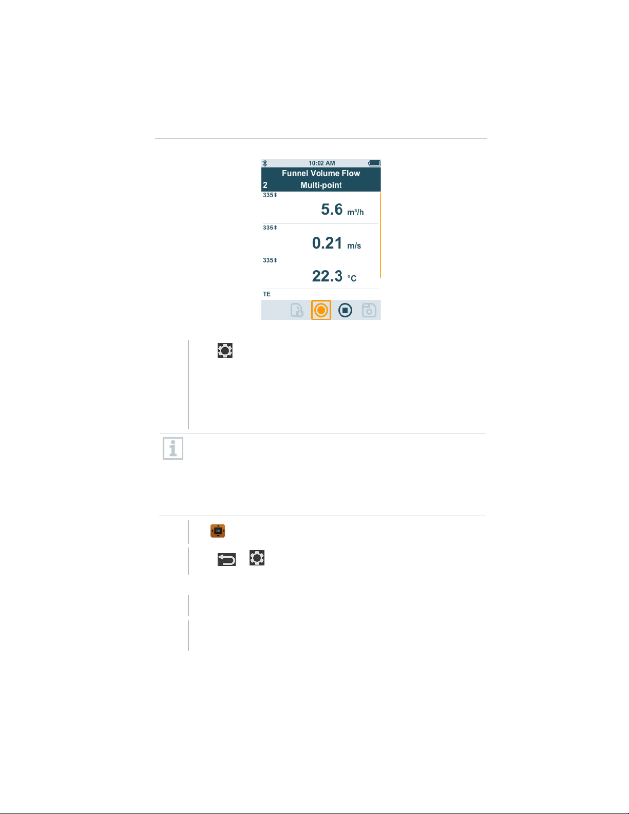
Press to configure the measurement.
You can set the following parameters:
- Measuring Type: multi-point/timed avg.
- Volume Flow Unit: m
3
/h, cfm, l/s, m3/s
Correction Factor: 1% to 200%
In a multi-point measurement, a mean value is calculated from the
individual measuring values.
In a timed average measurement, a mean value is calculated over a
certain period.
Several points can be measured. This generates a timed
average/multi-point total mean value.
Press or to exit the menu.
A suitable probe is connected to the measuring instrument.
Place the flow hood tightly on the air outlet. The flow hood must fully
36
Find Quality Products Online at: [email protected]
www.GlobalTestSupply.com
Page 36
4 Operation
2
4.5.7 Pitot volume flow application
Preparing for measurement
1
The Pitot tube factor for Pitot tubes is generally the same and must be
factor: 1.00
Carry out the measurement and save the measuring values.
[Pitot Volume
Flow]
The Pitot volume flow measurement is suitable for high velocities and flows
with a high particle content.
The application menu can only be accessed with testo 440 dP or used
in combination with a testo 510i with Bluetooth
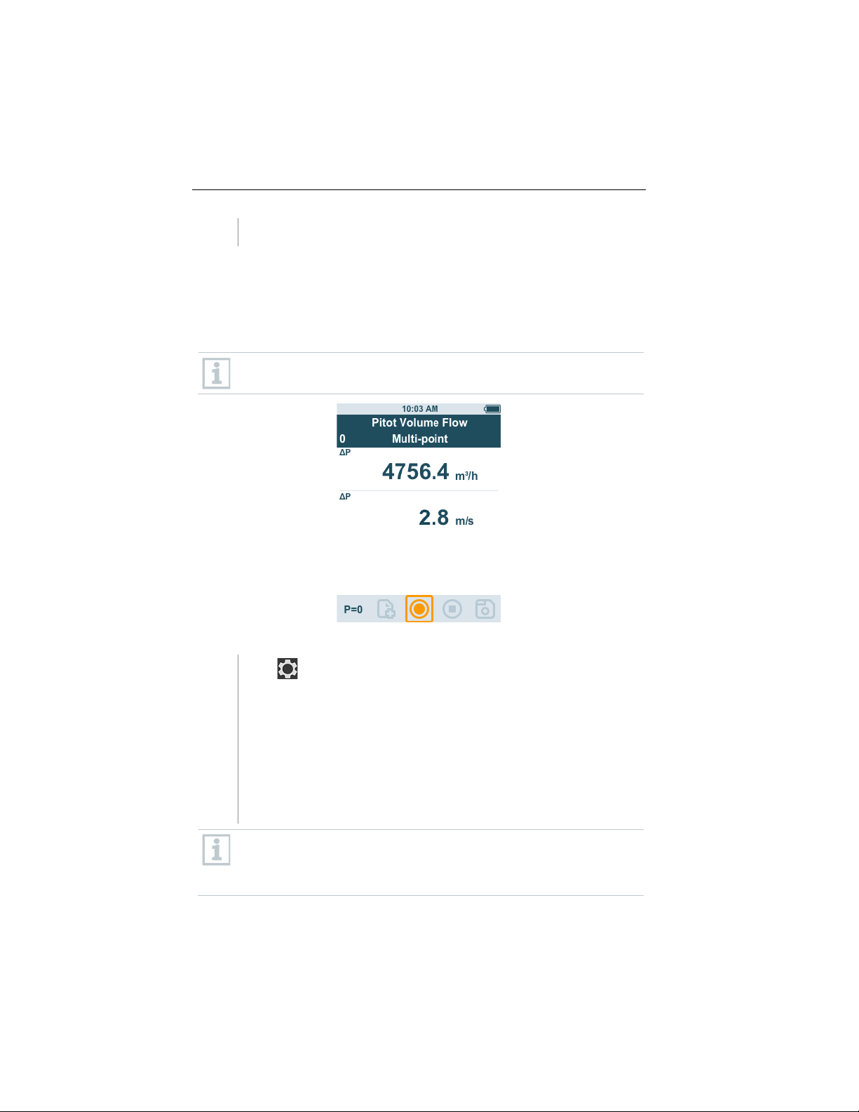
Press to configure the measurement.
You can set the following parameters:
- Geometry: round, rectangular or area
- Measuring Type: multi-point/timed avg.
- Units: mm or cm, mm
- Pitot Tube Factor: 0.00 to 1.00
- Correction Factor: 1% to 200%
- Volume Flow Unit: m
2
or cm2
3
/h, cfm, l/s, m3/s
®
.
entered prior to starting measurement:
- Prandtl Pitot tubes (0635 2045, 0635 2145, 0635 2345): Pitot tube
37
Find Quality Products Online at: [email protected]
www.GlobalTestSupply.com
Page 37
4 Operation
- Straight Pitot tubes (0635 2043, 0635 2143, 0635 2243): Pitot tube
manual for the Pitot tube factor or ask your supplier.
2
Use to select the required parameter and make settings.
3
Carrying out the measurement
A suitable probe is connected to the measuring instrument.
1
Define the channel parameters in the application menu.
2
Insert the Pitot tube in the channel.
3
Carry out the measurement and save the measuring values.
4.5.8 K-factor volume flow application
factor: 0.67
- Air flow velocity matrix (0699 7077): Pitot tube factor: 0.82
For Pitot tubes from other manufacturers, refer to the instruction
In a multi-point measurement, a mean value is calculated from the
individual measuring values.
In a timed average measurement, a mean value is calculated over a
certain period.
Several points can be measured. This generates a timed
average/multi-point total mean value.
Press or to exit the menu.
Observe the minimum clearances to points of discontinuity:
- From points of discontinuity upstream of the flow, observe a
clearance of at least six times the hydraulic diameter Dh = 4A/U (A:
channel cross-section, U: channel circumference).
- From points of discontinuity downstream of the flow, observe a
clearance of at least twice the hydraulic diameter Dh = 4A/U (A:
channel cross-section, U: channel circumference).
Volume Flow]
The testo 440 can determine the volume flow by measuring the reference
resistance and input of the K-factor. This allows the testo 440 to remain
38
[K-Factor
Find Quality Products Online at: [email protected]
www.GlobalTestSupply.com
Page 38
4 Operation
Prepare for measurement
1
connected to the air outlet during adjustment work and the changes in volume
flow can be read directly on the display.
The application menu can only be accessed with testo 440 dP or used
in combination with a testo 510i with Bluetooth
®
.
This process for determining volume flow can always be used when there are
appropriate specifications available from the component manufacturer. In line
with these specifications, the differential pressure is measured at a position
specified by the manufacturer or supplier. The volume flow is determined from
the differential pressure via a component-specific K-factor using the following
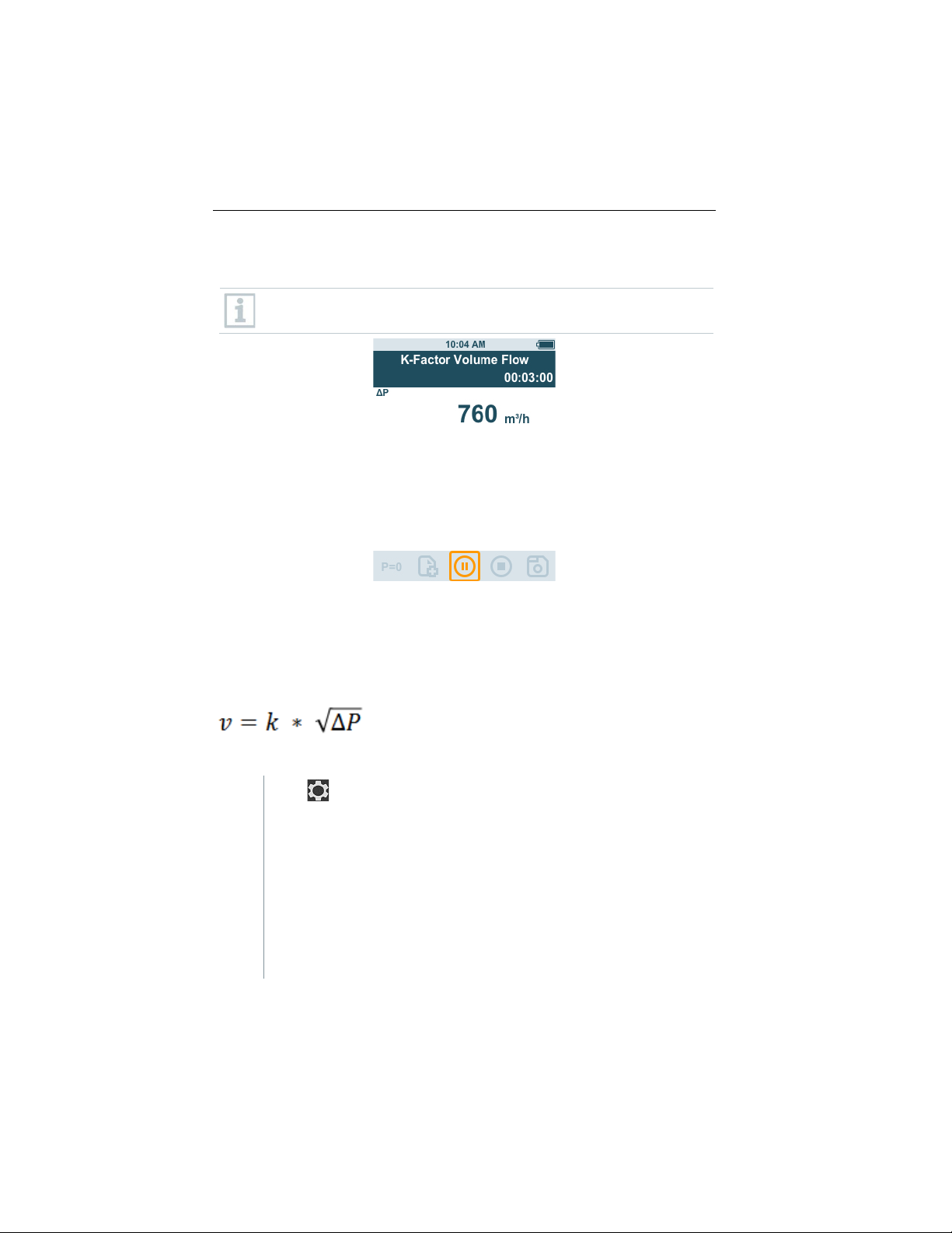
mathematical equation:
Press to configure the measurement.
You can make the following settings:
- Measuring Type: multi-point/timed avg.
- K-Factor: from 0.01 to 999.99
- Unit k-Factor:
Volume flow: m
3
/h, cfm, l/s, m3/s
Pressure: Pa, kPa, hPa, mbar, psi, mmH
Torr
- Volume Flow Unit: m3/h, cfm, l/s, m3/s
O, mmHg, inH2O, inHg,
2
39
Find Quality Products Online at: [email protected]
www.GlobalTestSupply.com
Page 39
4 Operation
2
3
Carrying out the measurement
1
Position the testo 440 ready for measurement and stabilise.
2
4.5.9 Heating/cooling load application
Bluetooth®
0636 9732
Temperature-humidity probe, fixed cable
CO2 probe including temperature and humidity sensor,
fixed cable
smartphone
In a multi-point measurement, a mean value is calculated from the
individual measuring values.
In a timed average measurement, a mean value is calculated over a
certain period.
Several points can be measured. This generates a timed
average/multi-point total mean value.
Press or to exit the menu.
Use to select the required parameter and make settings.
Carry out the measurement and save the measurement results.
[Heating/Cooling Load]
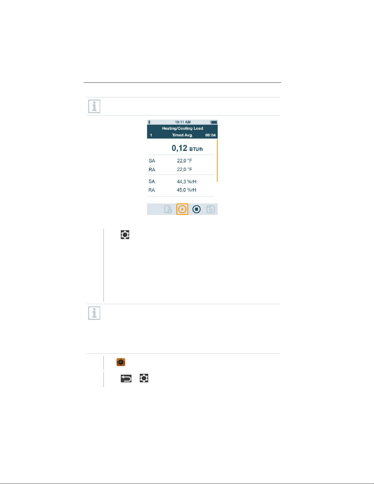
Use this application to calculate the heating/cooling load of a thermal
installation.
The Application menu is enabled by two of the following probes:
Order number Name
0636 9771 High-precision temperature-humidity probe with
0636 9772 High-precision temperature-humidity probe, fixed
cable
0636 9775 Robust temperature-humidity probe for temperatures
up to +180 °C, fixed cable
0636 9731 Temperature-humidity probe with Bluetooth®
0632 1551 CO2 probe with Bluetooth®, including temperature and
humidity sensor
0632 1552
0560 1605 testo 605 i - a thermohygrometer operated by
40
Find Quality Products Online at: [email protected]
www.GlobalTestSupply.com
Page 40
4 Operation
A minimum of two probes are to be connected in each combination via
Preparing for measurement
1
2
Use to select the required parameter and make settings.
3
Bluetooth® and cable.
Press to configure the measurement.
You can set the following parameters:
- SA Probe ID
- RA Probe ID
- Measuring Type: multi-point/timed avg.
- Volume Flow Unit: m3/h, cfm, l/s, m3/s
- Volume flow: 0.0 to 99999.0
- Heating/Cooling Load Unit: kW, BTU/h
In a multi-point measurement, a mean value is calculated from the
individual measuring values.
In a timed average measurement, a mean value is calculated over a
certain period.
Several points can be measured. This generates a timed
average/multi-point total mean value.
Press or to exit the menu.
41
Find Quality Products Online at: [email protected]
www.GlobalTestSupply.com
Page 41
4 Operation
Carrying out the measurement
Two suitable probes are connected to the measuring instrument.
1
2
3
from these.
4
Carry out the measurement and save the measuring values.
4.5.10 CO measurement application
Order no.
Designation
0632 1271
CO probe with Bluetooth®
0632 1272
Display
Meaning
Green
Low risk
Yellow
Medium risk
Red
High risk
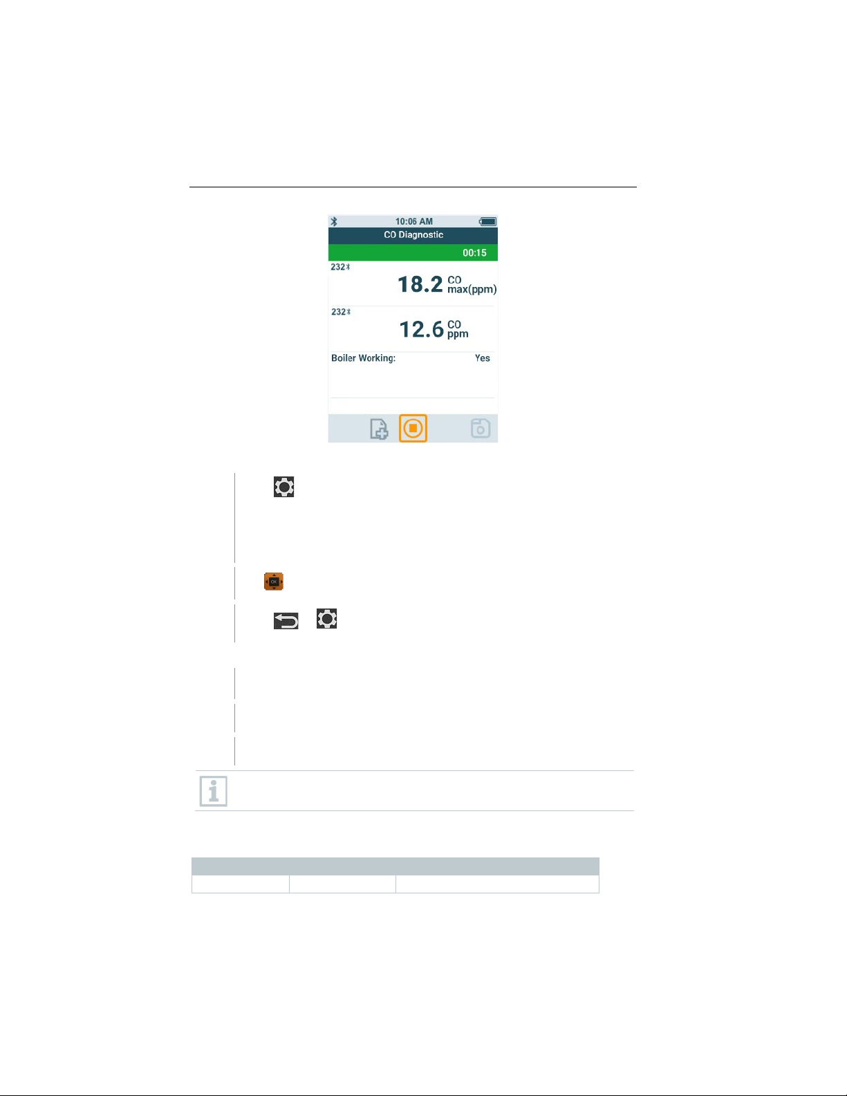
Measure the CO content with this application. The application menu is enabled
by the following probes:
Place the SA-configured probes in the supply air of your system.
Place the RA-configured probes in the exhaust air of your system.
The humidity and temperature values for supply air and exhaust air
are shown on the display with the heating/cooling load calculated
[CO Diagnostic]
CO probe, fixed cable
Only one probe can be connected to the testo 440 by Bluetooth®.
The display shows the CO content using the traffic light principle.
42
Find Quality Products Online at: [email protected]
www.GlobalTestSupply.com
Page 42
4 Operation
1
2
Use to select the required parameter and make settings.
3
A suitable probe is connected to the measuring instrument.
1
Position the CO probe ready for measurement.
2
If the measurement is terminated prematurely, the measurement is
Yes
Value
Display
Result
0 to 25 ppm
Green
OK
Preparing for measurement
Press to configure the measurement.
You can set the following parameters
- Boiler Working: Yes / No
- Duration: 30s / 60s / 90s / 120s
Press or to exit the menu.
Carrying out the measurement
Carry out the measurement and save the measurement results.
considered a failure.
Interpretation of the measurement results
If parameter [Boiler Working =
], then CO max:
43
Find Quality Products Online at: [email protected]
www.GlobalTestSupply.com
Page 43
4 Operation
Value
Display
Result
0 to 30 ppm
Green
OK
31 to 50 ppm
yellow
Irregularity detected
4.5.11 Mould indication application
Bluetooth®
cable
0636 9731
Temperature-humidity probe with Bluetooth®
0636 9732
Temperature-humidity probe, fixed cable
and humidity sensor
sensor, fixed cable
0615 1712
Robust air probe – with NTC temperature sensor
Temperature probe with Velcro and NTC temperature
manufacturers)
A minimum of 1 temperature probe (TE, NTC, 805i) and 1 humidity
Value Display Result
> 25 ppm Red Serious irregularity
If parameter [Boiler Working = No], then CO max:
> 50 ppm Red Serious irregularity
[Mould Indication]
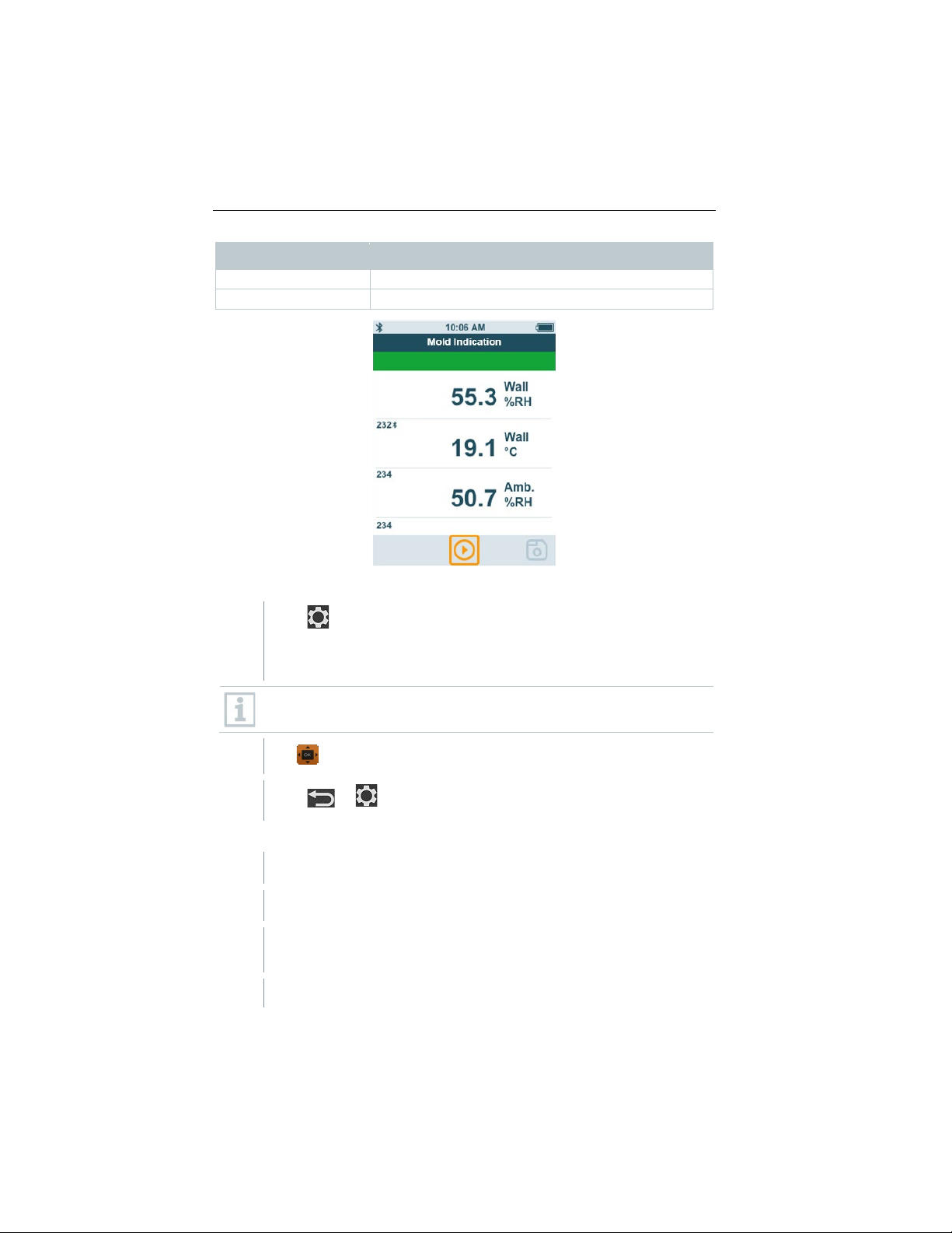
Use this application to measure the risk of mould in rooms.
The application menu is enabled by the following probes:
Order number Name
0636 9771 High-precision temperature-humidity probe with
0636 9772 High-precision temperature-humidity probe, fixed
0632 1551 CO2 probe with Bluetooth®, including temperature
0632 1552 CO2 probe including temperature and humidity
0615 4611
sensor
0560 1805 testo 805i - infrared thermometer operated by
smartphone
TE (independent of
probe is to be connected via Bluetooth® and cable.
Only one probe can be connected to the testo 440 by Bluetooth®.
The display shows the risk of mould using the traffic light system.
Display Meaning
Green Low risk
44
Find Quality Products Online at: [email protected]
www.GlobalTestSupply.com
Page 44
Display Meaning
Yellow
Medium risk
Red
High risk
Preparing for measurement
1
-
2
Use to select the required parameter and make settings.
3
Carrying out the measurement
A suitable probe is connected to the measuring instrument.
1
Take a humidity measurement in the room.
2
presumed risk of mould.
4 Operation
Press to configure the measurement.
If a testo 805i is used, the following settings can be made:
Emissivity
Please refer to the testo 805i instruction manual for detailed
information on emissivity.
Press or to exit the menu.
Take a temperature measurement at the spot where there is a
The risk of mould is indicated by a colour indicator on the display.
45
Find Quality Products Online at: [email protected]
www.GlobalTestSupply.com
Page 45
4 Operation
3
Save the measurement.
4.5.12 Turbulence measurement application
case)
Yellow
Draught rate 21-30%
Red
Draught rate 31-100%
Rate]
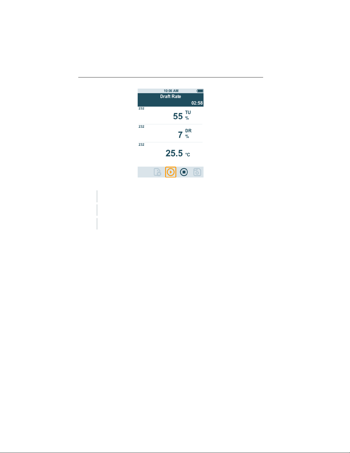
With this application menu, the measurement of the degree of turbulence and
draught can be determined in accordance with DIN EN 13779 or DIN EN ISO
7730.
The measurement is carried out automatically over a period of 3 minutes. For
ideal implementation, we recommend the use of:
Order number Name
0554 1590 Measuring tripod for comfort level measurements with
standard-compliant positioning of probes (including
The application menu is enabled by the following probe:
Order number Name
0628 0152 Turbulence probe, fixed cable
The probe requires a warm-up period of around 3 seconds after
connection to the testo 440. Carry out the measurement after this.
The display shows the draught rate using the traffic light system.
Display Meaning
Green Draught rate 0-20%
[Draught
46
Find Quality Products Online at: [email protected]
www.GlobalTestSupply.com
Page 46
4 Operation
Carrying out the measurement
A suitable probe is connected to the measuring instrument.
1
Attach the probe to the tripod for the best measuring task result.
2
Carry out the measurement and save the measuring values.
4.5.13 Performing long-term measurement
application
maximum
[Logger Mode]
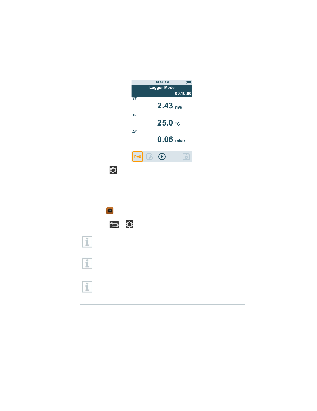
This application menu allows you to record measurement data over a userdefined period of time at a specified interval.
All compatible probes can be used.
The
• 1x TC
• 1x Bluetooth
• 1x cable probe
of following probes can be active at the same time:
®
probe
47
Find Quality Products Online at: [email protected]
www.GlobalTestSupply.com
Page 47
4 Operation
1
2
Use to select the required parameter and make settings.
3
The maximum measurement period depends on the condition of the
testo recommends using an external power supply for each micro USB
Press to configure the measurement.
You can make the following settings:
- Measuring interval: in s
- Measurement duration: in hrs and min
Press or to exit the menu.
battery, how much free memory there is and the probe used. This is
displayed during configuration.
In the long-term mode application [Logger Mode], the measurement
(from firmware version 1.0.4) is always saved automatically at the end
of the configured measurement period.
in the case of particularly long measurements. It is then possible to
record significantly longer measurement series.
0554 1105 - USB mains unit including cable
48
Find Quality Products Online at: [email protected]
www.GlobalTestSupply.com
Page 48
5 Maintenance
5.1 Battery replacement
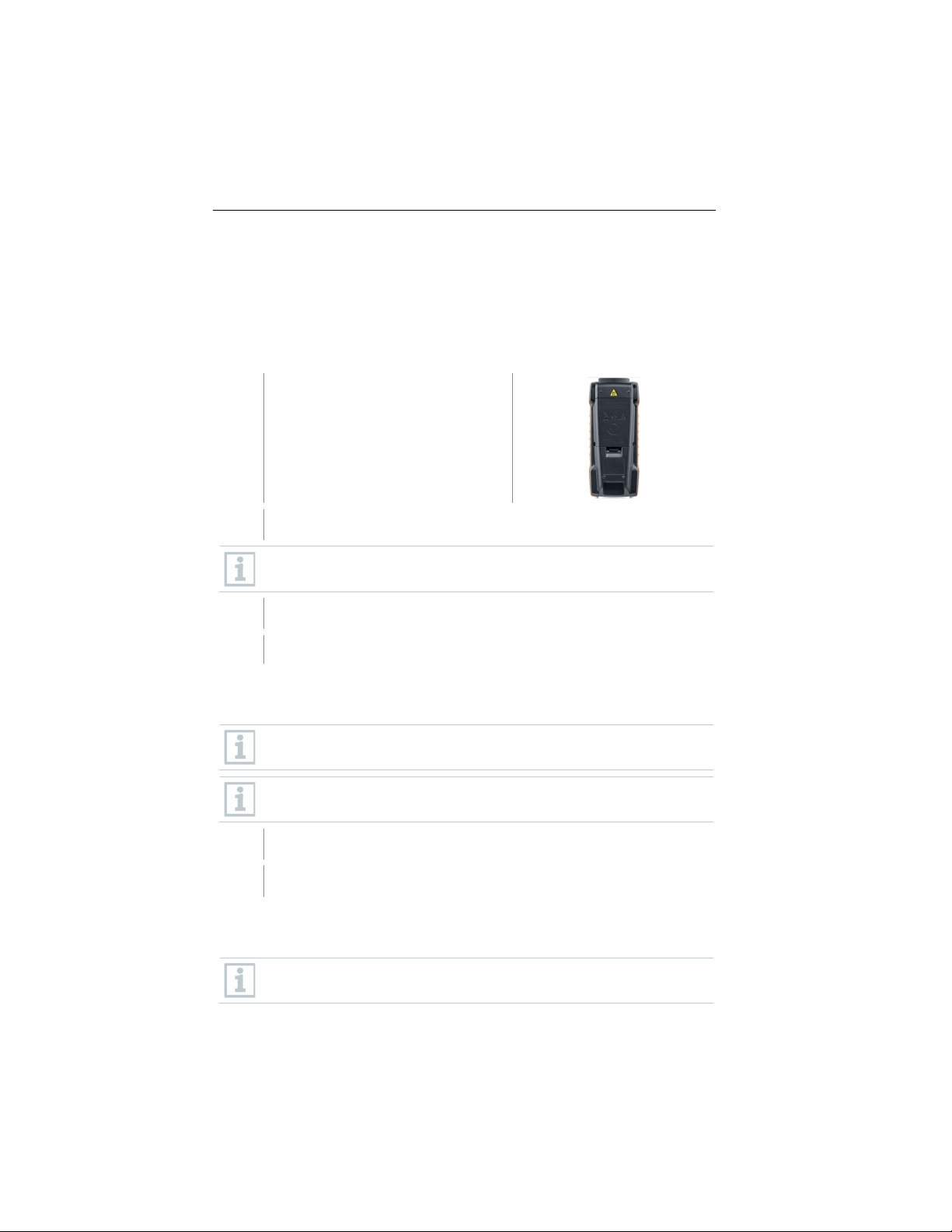
1
Open the battery compartment cover.
2
Replace the batteries. Observe the polarity!
3
Close the battery compartment cover.
5.2 Cleaning testo 440
household
1
2
If necessary, clean all the connections using a damp cloth.
5.3 Calibration
5 Maintenance
Only use new branded batteries. If a partially exhausted battery is
inserted, the battery capacity will not be calculated correctly.
The testo 440 is ready for use.
Never use abrasive cleaning agents or solvents; instead use
detergent or soapy water.
Always keep the connections clean and free of grease and other
deposits.
Clean the unit with a damp cloth and dry it.
The probe and the handle are supplied with a factory calibration
certificate as standard.
49
Find Quality Products Online at: [email protected]
www.GlobalTestSupply.com
Page 49
5 Maintenance
In many applications, it is recommended that you recalibrate the probe
5.4 Carrying out a firmware update
You have downloaded the firmware file to your computer.
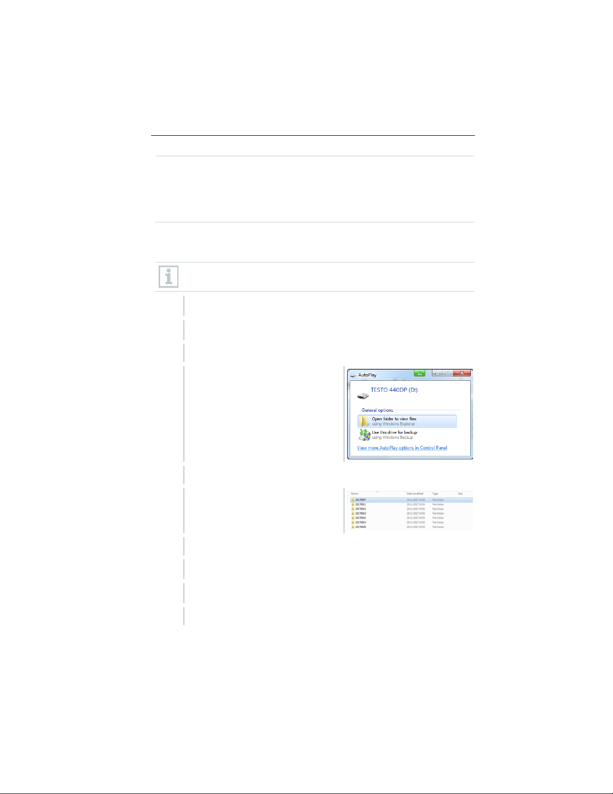
1
Connect the testo 440 to your computer using the micro USB cable.
AutoPlay
2
Open folder [Open folder to
view files]
3
4
Disconnect the testo 440 from the computer.
5
with the handle and the testo 440 once a year.
This can be carried out by Testo Industrial Services (TIS) or other
certified service providers.
Please contact Testo for further information.
Information on current firmware for testo 440 can be found at
on the product page.
The
window opens automatically.
Click on
to view files.
The window with available file folders opens.
Drag the firmware file to the open
window.
The copying process is completed.
Switch the testo 440 off and then on again.
The firmware is automatically installed.
50
Find Quality Products Online at: [email protected]
www.GlobalTestSupply.com
Page 50

6 Technical data
6 Technical data
Measuring range
-40 to +150 °C
±0.5% of m.v. (remaining meas. range)
Resolution
0.1 °C
Measuring range
-200 to +1370 °C
Resolution
0.1 °C
Measuring range
-150 to +150 hPa
(1.01 to 150 hPa)
Resolution
0.01 hPa
connection
corresponding plug
Bluetooth© probe
1x digital Bluetooth© probe or testo Smart Probe
Differential pressure
-
+
Temperature (NTC) testo 440 testo 440 dP
Accuracy (±1 digit) at
22 °C
Temperature (TE) testo 440 testo 440 dP
Accuracy (±1 digit) ±(0.3 °C + 0.3% of m.v.)
Pressure testo 440 testo 440 dP*
Accuracy (±1 digit) at
22 °C
* The accuracy specification applies immediately after zeroing of the sensor. The sensor is affected by
changes in position or attachment to magnetic surfaces. Therefore, zero the sensor only in the
instrument end position.
Probe connections testo 440 testo 440 dP
Type K thermocouple
±0.4 °C (-40 to -25.1 °C)
±0.3 °C (-25 to +74.9 °C)
±0.4 °C (+75 to +99.9 °C)
±0.5 °C for cold junction
±0.05 hPa (0 to +1.00
hPa)
±0.2 hPa + 1.5% of m.v.
1x
Testo Universal
1x
Connector (TUC) for
connection of cabled
probes with
51
Find Quality Products Online at: [email protected]
www.GlobalTestSupply.com
Page 51

6 Technical data
Operating temperature
-20 to +50 °C
Storage temperature
-20 to +50 °C
Battery life
12 hours
Weight
250 g
Dimensions
154 x 65 x 32 mm
temperature sensor, fixed cable
sensor, fixed cable
temperature sensor, fixed cable
probe, fixed cable
fixed cable
0635 0551
Lux probe
11 hrs
0628 0152
Turbulence probe, fixed cable
9 hrs
Technical data testo 440 testo 440 dP
Bluetooth© range (latest
generation testo climate
probes with Bluetooth©
Bluetooth© range (Smart
Probes)
Battery type 3 x AA batteries
Connected probe
(order no.)
0635 1032 Hot wire probe including
0635 1572 Hot wire probe including
0635 9532 Vane probe (Ø 16 mm) fixed cable 11 hrs
0635 9372 High-precision vane probe (Ø
0635 9432 Vane probe (Ø 100 mm) including
0636 9772 High-precision temperature-
Name Battery life*
temperature and humidity sensor,
fixed cable
100 mm) including temperature
humidity
20 m free field
3 m free field
8 hrs
8 hrs
10 hrs
10 hrs
12 hrs
0636 9775 Robust temperature-humidity probe
for temperatures up to +180 °C,
0636 9732 Temperature-humidity probe, fixed
cable
0632 1552 CO2 probes including temperature
and humidity sensor, fixed cable
0632 1272 CO probe, fixed cable 11 hrs
52
Find Quality Products Online at: [email protected]
www.GlobalTestSupply.com
12 hrs
12 hrs
8 hrs
Page 52

7 Tips and assistance
0635 1052
Fume cupboard probe, fixed cable
9 hrs
7 Tips and assistance
7.1 Questions and answers
7.1.1 LED status Bluetooth® probe
for the Bluetooth® connection.
with Bluetooth®.
7.1.2 Hot wire measurement not possible
7.2 Accessories and spare parts
Bluetooth® probe
and humidity sensor
temperature sensor
Connected probe
Name Battery life*
(order no.)
* All information at 22 °C, 50% screen brightness, power saving mode ON, A uto-Off off.
LED status Description
Flashing red Low battery status
Flashing yellow Probe is switched on and searching
Flashing green Probe is switched on and connected
Before measurement, the cap must be opened on the hot wire probe.
Order number Name
0635 1571 Hot wire probe with Bluetooth®, including temperature
0635 9571 Vane probe (Ø 16 mm) with Bluetooth®, including
0635 9371 High-precision vane probe (Ø 100 mm) with
®
Bluetooth
, including temperature sensor
0635 9431 Vane probe (Ø 100 mm) with Bluetooth®, including
temperature sensor
53
Find Quality Products Online at: [email protected]
www.GlobalTestSupply.com
Page 53

0636 9731
Temperature-humidity probe with Bluetooth®
0632 1271
CO probe with Bluetooth®
Cable probe
cable
sensor, fixed cable
fixed cable
fixed cable
cable
up to +180 °C, fixed cable
0636 9732
Temperature-humidity probe, fixed cable
0635 0551
Lux probe
sensor, fixed cable
0632 1272
CO probe, fixed cable
0628 0152
Turbulence probe, fixed cable
7 Tips and assistance
Order number Name
0636 9771 High-precision temperature-humidity probe with
Bluetooth
0632 1551 CO2 probe with Bluetooth®, including temperature
and humidity sensor
Order number Name
0635 1032 Hot wire probe including temperature sensor, fixed
0635 1572 Hot wire probe including temperature and humidity
0635 9572 Vane probe (Ø 16 mm) including temperature sensor,
0635 9372 High-precision vane probe (Ø 100 mm) including
temperature sensor, fixed cable
0635 9432 Vane probe (Ø 100 mm) including temperature sensor,
®
0636 9772 High-precision temperature-humidity probe, fixed
0636 9775 Robust temperature-humidity probe for temperatures
0632 1552 CO2 probe including temperature and humidity
0635 9532 Vane probe (Ø 16 mm) fixed cable
0635 1052 Fume cupboard probe, fixed cable
54
Find Quality Products Online at: [email protected]
www.GlobalTestSupply.com
 Loading...