


pdfcrowd.comopen in browser PRO version
Are you a developer? Try out the HTML to PDF API
BACK TO
ALL MANUALS
OUTLAW OPERATOR INSTRUCTION MANUAL
Table of Contents
pdfcrowd.comopen in browser PRO version
Are you a developer? Try out the HTML to PDF API
GETTING STARTED
CONTROLS
AIR TEST - SELF GUIDED TUTORIAL
FIELD USE
GENERAL INFORMATION
LIST OF FIGURES
Congratulations on the purchase of your Tesoro Outlaw Metal Detector.
You’ve taken the first step to be successful in treasure hunting, purchasing a high quality metal
detector.
The second step is to learn to use your metal detector properly. Please take the time to read
and understand the manual. It will walk you through assembly, the controls, an air test, and field
use.
The third step is to hunt where treasure may be found. Your local dealer may provide insight, as
well as treasure hunting magazines and books. Your research about locations and history will
be as important as your choice of detectors.
The final step is to be persistent. There is no substitute for time in the field. Your success

pdfcrowd.comopen in browser PRO version
Are you a developer? Try out the HTML to PDF API
should grow with your experience and confidence.
All of us at Tesoro wish you success and enjoyment in your treasure hunting experience.
Vince Gifford
GETTING STARTED - UNPACKING THE BOX
Your Outlaw was shipped with these parts:
1 Upper Pole Assembly
– Fully assembled, including upper pole stem with handle grip, padded arm bracket
and control housing.
1 Middle Pole Assembly With Pole Lock
3 ABS Lower Pole Assembly
– Fully assembled nylon pole, complete with two friction washers, wingbolt, and wing
nut.
1 5.75” Round Concentric
Searchcoil with 3.5’ Cable

pdfcrowd.comopen in browser PRO version
Are you a developer? Try out the HTML to PDF API
1 8” Round, Concentric
Searchcoil with 3.5’ Cable
1 12x10” Wide Scan Searchcoil
with 3.5’ Cable
1 9 volt Alkaline Battery
3 One Wrap Velcro Strips (to hold
coil cables)
1 Operator Instruction Manual
1 Warranty Card Figure 1 – Out of the Box
GETTING STARTED
If any of these items are missing, immediately contact the Tesoro Authorized Dealer where you
purchased your detector.
Assembly of the Outlaw is simple and requires no special tools. Just install the battery, mount
the searchcoils on the lower pole assemblies, connect the three pole assemblies together,
wrap the excess cable around the pole and plug the cable into the control housing. Finally,
adjust the pole length and searchcoil angle and you’re ready!
INSTALLING THE BATTERY

pdfcrowd.comopen in browser PRO version
Are you a developer? Try out the HTML to PDF API
To install or replace the battery, first make sure the Sensitivity (SENS) control is set to OFF turned completely counterclockwise past the “click”. Remove the battery door from the back of
the control housing. Do this by pressing your thumb firmly on the louvered square - at the
bottom of the battery door- and sliding the battery door upward (in the direction of the arrow)
while pushing.
Check the polarity on the battery and on the diagram inside the battery compartment. Make
sure they match when you insert the fresh 9 volt alkaline battery into the compartment.
Replace the battery door by sliding it into place making sure the upper mount slots are in line
and the lock tongue is snapped in place.
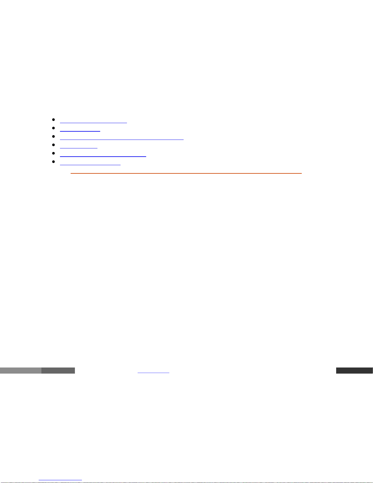
ATTACHING LOWER POLES TO THE COILS
1. On a lower pole assembly,
remove the mounting screw and
thumb nut from the black nylon
pole.
Leave the friction washers in the
recessed feature of the pole tip.
Figure 2 – Removing Mounting Screw and Thumb
Nut
pdfcrowd.comopen in browser PRO version
Are you a developer? Try out the HTML to PDF API
2. Insert the pole tip between the
mounting ears of the searchcoil
and align the holes of the pole tip
and friction washers with those of
the mounting ears.
Note: The pole tip should fit very
snugly into the mounting ears with
friction washers in place.
Figure 3 – Pole Tip In Searchcoil Mounting Ears
3. Insert the mounting screw
through the holes in the mounting
ears and pole tip (entering from the
side opposite the cable
connection).
4. Install the thumb nut on the
mounting screw and tighten by
hand.
Note: Do not overtighten the thumb
nut. It should be snug but not too
difficult to loosen up.
Figure 4 – Mounting Coil to Lower Pole
pdfcrowd.comopen in browser PRO version
Are you a developer? Try out the HTML to PDF API
5. Wrap the cable around the pole
and use one-wrap Velcro strip to
hold cable per Figure 5. This will
prevent the cable from flopping
while not in use.
Figure 5 – Lower Poles Properly Attached to Coils
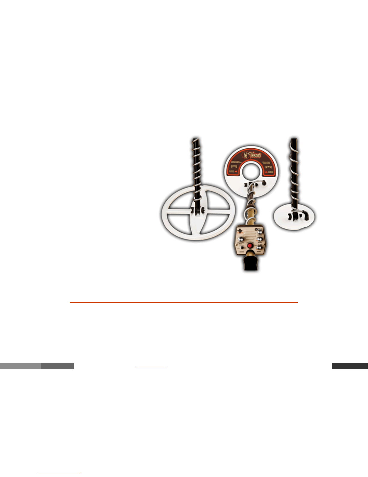
ASSEMBLING YOUR DETECTOR
1. Loosen pole lock on the upper pole assembly.
Depress the two spring buttons on the middle pole
assembly and slide the middle pole assembly into
the upper pole assembly until the spring buttons
pdfcrowd.comopen in browser PRO version
Are you a developer? Try out the HTML to PDF API
the upper pole assembly until the spring buttons
click into the holes, locking the two assemblies into
place. Tighten the pole lock to secure the two
assemblies together.
Figure 6 – Attach Middle and Upper
Pole Assemblies
2. Choose the coil you’re going to use. Remove onewrap Velcro strip from lower pole assembly.
Loosen the pole lock on the middle pole assembly.
Depress the first two spring buttons on the lower
pole assembly and slide lower pole into middle
pole, depress the second two spring buttons and
slide until spring buttons click into a set of
adjustment holes. Select the adjustment holes that
give you the proper overall pole length you require
(only one set of spring buttons will be in adjustment
holes depending on your length setting). Turn pole
lock to tighten, locking the assembly into place.
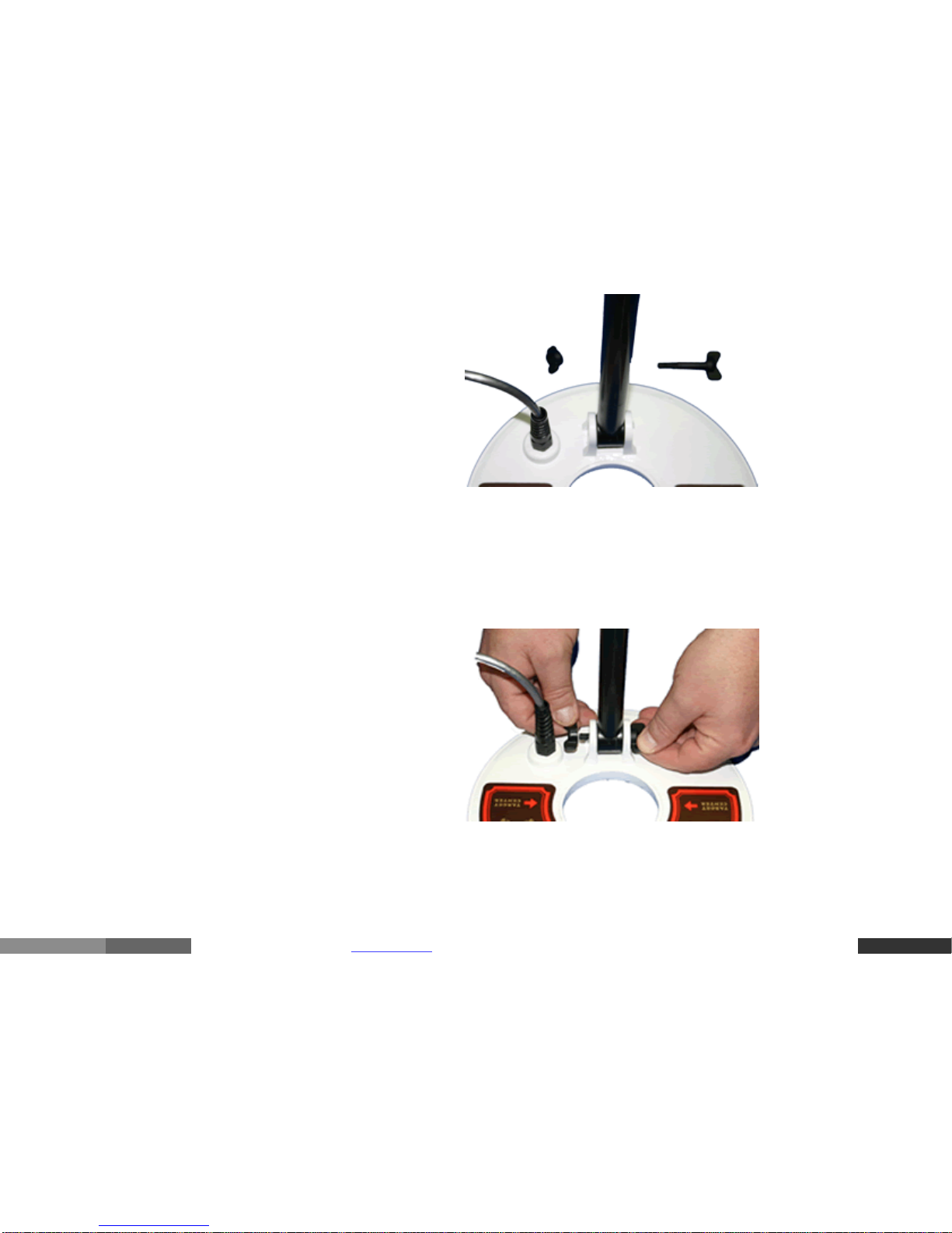
3. Wrap the cable around the pole leaving enough slack near the searchcoil to permit
searchcoil adjustment. (See Figure 8)
Note: Do not allow the cable to flop loosely over the searchcoil. Since the detector is sensitive
enough to “see” the tiny wires in the cable, a floppy cable can cause false signals as the
searchcoil senses the moving wires.
4. Plug the male cable end into the female connector
on the control housing and tighten the cable thumb
nut. You are finished!
Note: You will want to adjust the pole length and the
searchcoil angle to your preference. See Field Use
pdfcrowd.comopen in browser PRO version
Are you a developer? Try out the HTML to PDF API
Section.
Figure 7 – Connecting the Cable
Figure 8 – Properly Assembled Outlaw
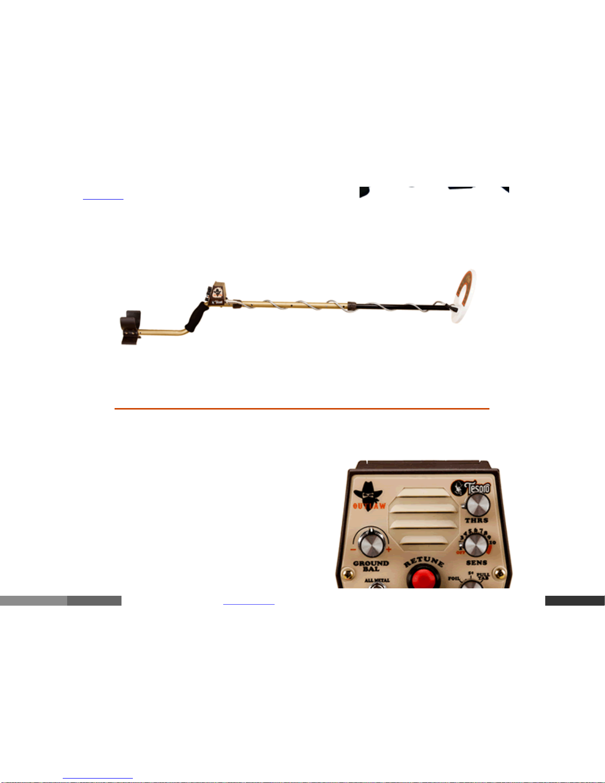
CONTROLS
The Outlaw Metal Detector has only six controls,
all mounted on the front panel of the housing for
fingertip adjustment. How these controls should
be set for peak performance will depend on the
type of metal you are searching for, search site
conditions, mineral content of the soil and so
forth. Use the information in this section and the
Field Use Section “Tuning Your Detector” as a
pdfcrowd.comopen in browser PRO version
Are you a developer? Try out the HTML to PDF API
basis for setting the controls on your detector.
Using your Outlaw Metal Detector in the field will
allow you to learn the detector’s responses to
various conditions and will guide you in fine
tuning the detector’s operating controls.
Figure 9 – Outlaw Controls
GROUND BAL
This rotary control switch has one function:
Adjust the ground balance of the detector.
Turning the knob counterclockwise (-direction) will move the ground balance in a negative
direction. Turning the knob clockwise (+direction) will move the ground balance in a positive
direction.
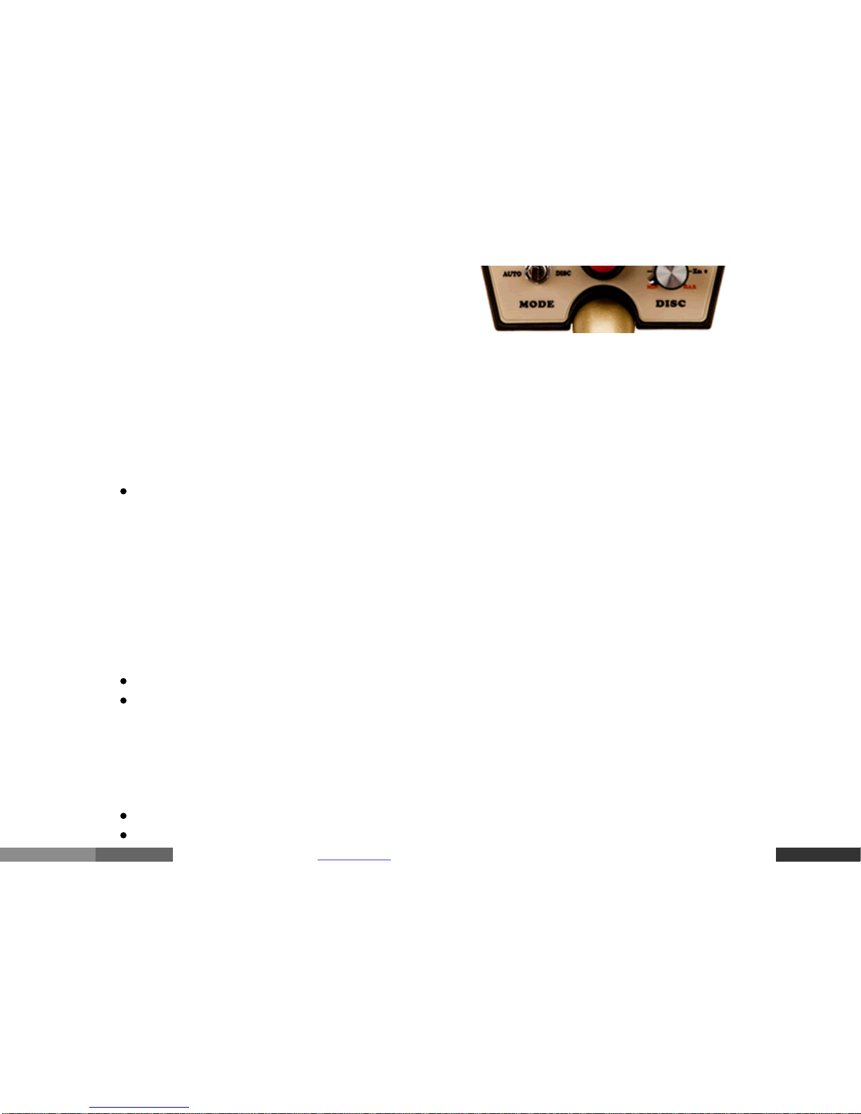
MODE
This three-position switch has two functions:
Select the operating MODE (ALL METAL or Discriminate DISC)
Select the retune speed of the ALL METAL MODE (No Motion or AUTO Tune)
RETUNE
This push button has two functions:
Put the detector in the ALL METAL MODE
Retunes the threshold of the current signal

pdfcrowd.comopen in browser PRO version
Are you a developer? Try out the HTML to PDF API
DISC
This rotary control has one function:
Set the level of discrimination
Turning the knob counterclockwise (MIN) will lower the amount of discrimination, lowering the
amount of targets discriminated out. Turning the knob clockwise (MAX) will increase the
amount of discrimination, increasing the type of targets discriminated out.
SENS
This rotary control switch has three functions:
Turns the detector ON and OFF
Activates the automatic Audio Battery Test
Adjusts the sensitivity level for the Discrimination (DISC) MODE
Turning the knob completely counterclockwise until it clicks turns the detector off. Turning the
knob clockwise from the OFF position turns the detector on. It also activates the automatic
battery test. The battery test is an audio tone. The volume and duration of the tone is related to
the battery strength. When the battery test is no longer heard, the 9 V battery needs to be
replaced. Continuing to turn the knob clockwise will increase the sensitivity in the
Discrimination (DISC) MODE.
THRS
This rotary control has one function:

pdfcrowd.comopen in browser PRO version
Are you a developer? Try out the HTML to PDF API
Set the level of the threshold
The threshold is the minimum noise at the speaker in the ALL METAL MODE. Turning the
Threshold (THRS) clockwise will increase the threshold. Turning the Threshold (THRS)
counterclockwise will decrease the threshold.
AIR TEST — SELF–GUIDED TUTORIAL
INTRODUCTION
The air test is designed to introduce the use of controls for the Outlaw Metal Detector. If you
have never owned a metal detector before, follow each step carefully.
You will need:
Fully assembled Outlaw Metal Detector
Three newer coins: a penny (1984 or newer), a nickel and a quarter
A non-metal table or counter surface
Approximately 20 minutes to complete the Air Test
Prepare for the Air Test:
Place your assembled Outlaw Metal Detector on the non-metal surface as shown in
Figure 10
Make sure there are no metal objects near the coil
Remove any jewelry from your hands and wrists
 Loading...