


NSG 5000 SCHAFFNER INSTRUMENTS
Interference Test System
NSG 5000
Operating Instructions
1-1

SCHAFFNER INSTRUMENTS NSG 5000
CONTENTS
1 Introduction ............................................................................... 1-4
2 NSG 5000 System Overview .................................................... 1-6
2.1 Power Entry Unit ................................................................ 1-7
2.2 Control Unit ................................................................. ...... 1-9
2.3 HV - Supply ..................................................................... 1-11
2.4 Battery Switch ................................................................. 1-12
2.5 System Block Diagram ................................................... 1-14
2.6 External Connection of Pulse 4 Amplifiers ...................... 1-15
3 Safety Advice ........................................................................... 1-16
3.1 General ............................................................................ 1-16
3.2 Installation ................................................................. ...... 1-17
3.3 Test Execution ................................................................ 1-18
3.4 Dangers Concerning the Generator ............................... 1-18
3.5 Dangers Concerning the DUT ........................................ 1-19
3.6 Applicable Safety Standards ............................................ 1-20
3.7 General Specifications ..................................................... 1-20
4 Putting into service ................................................................ 1-21
5 Remote Programming ............................................................ 1-22
5.1 Conventions .................................................................... 1-22
5.2 Short and Long forms ..................................................... 1-23
5.3 SCPI messages .............................................................. 1-23
5.4 NSG 5000 Command Description......................... .......... 1-25
5.4.1 SOURce Subsystem ........................................... 1-28
5.4.2 INITiate Subsystem ............................................. 1-34
5.4.3 INSTrument Subsystem ..................................... . 1-35
5.4.4 OUTput Subsystem ............................................. 1-36
5.4.5 TRIGger Subsystem ............................................ 1-37
5.4.6 ABORT Subsystem ............................................. 1-39
5.4.7 PAUSE Subsystem ............................................. 1-39
5.4.8 DIAGnostic Subsystem ....................................... 1-40
5.4.9 List Subsystem .................................................... 1-41
5.4.10 Calibration Subsystem ........................................ 1-41
5.5 SCPI Mandatory commands ........................................... 1-43
5.6 IEEE 488.2 Mandatory commands ................................. 1-43
1-2

NSG 5000 SCHAFFNER INSTRUMENTS
6 External trigger and control signals ................................... .. 1-44
6.1 Start/Stop Signal .............................................................. 1-44
6.2 Fail Signal ........................................................................ 1-45
6.3 Cro Trigger ...................................................................... 1-45
6.4 Test End .......................................................................... 1-46
7 RS232 wiring diagram ............................................................. 1-47
7.1 Optical Interface .............................................................. 1-47
8 IEEE Address Setting .............................................................. 1-48
9 Schaffner Sales Offices........................................................... 1-49
1-3

SCHAFFNER INSTRUMENTS NSG 5000
1 Introduction
The NSG 5000 EMC test system is designed for testing automotive electronic
components and parts. Automotive EMC test requirements are covered
primarily in the ISO 7637-1 and the ISO 7637-2 standards. These standards
outline seven basic pulse types that are used for automotive EMC testing. The
NSG 5000 system is a modular instrument that can generate all of the pulses
described in the ISO standard and in many cases to a higher specification than
that specified in the standard.
The NSG 5000 is a modular instrument where the pulse generators are
designed as plug-in modules that fit into the NSG 5000 mainframe.
1-4

NSG 5000 SCHAFFNER INSTRUMENTS
Due to the modular structure of the NSG 5000 you configure a test system that
provides only the pulse requirements that are required for your application.
- It should be noted that pulses of similar specification and energy
requirements are usually housed in the same plug-in unit. For example
the ISO pulses 1, 2 and 6 are all supplied within the same plug-in.
The NSG 5000 is fully programmable over an RS232 or (optional) IEEE488
interface bus. A graphical Windows program "Win5000" is available to provide
full remote control via a PC computer. This program allows you to generate
pulse sequences, including dynamic ramping, and to generate hardcopy
printouts of the test results.
The main features of the NSG 5000 could be summarised as follows,
- Modular construction, pulse modules plug into main chassis.
- Exceeds specifications set out in the ISO, DIN and SAE standards.
- Remote controllable via RS232 or IEEE488 interface.
- Built in selftest to verify basic pulse operation
- Internal multiplex bus system (all pulses available from the front of
NSG 5003 plug in).
- Remote control protocol uses SCPI standard.
- Compact construction, 12 inches high (30 cm).
- 19 inch rack mountable.
- Windows software program available (as option).
- DUT FAIL, Start/Stop, Test End, and CRO Trig signals available for
interfacing with other test equipment.
- 68000 based control unit provides flexible and fast operation.
1-5

SCHAFFNER INSTRUMENTS NSG 5000
2 NSG 5000 System Overview
The NSG 5000 mainframe is designed to take the pulse plug in units from
the front. The system support electronics are plugged in from the rear.
These rear plug in units are not generally removed by the user. These units
have a modular construction to facilitate easy maintenance and to allow for
future upgrades to the NSG 5000 system. The plug-in units in question are,
- HV Supply this is a solid state high voltage programmable power supply
that provides the required charging voltage to the pulse generators.
- Power Entry this unit facilitates the connection of the mains input to the
system and the connection of the battery supply to the power bus. In
addition it also provides the input/output connections for the external control
signals DUT FAIL, START/STOP, TEST END and CRO. TRIG
- Battery Switch this unit contains a solid state switch and timing
electronics which are used for precise timing control of the ON and OFF
periods of the battery power supplied to the Device Under Test (DUT). This
is required to meet some of the timing requirements specified in the
standards, particularly for pulses 1, 2 and 6.
- Control this unit contains the 68000 based processor board that controls
the complete system. The remote control interfaces RS232 and IEEE488
are also available via this unit, as well as the optional Pulse 4/4c control
board.
1-6

NSG 5000 SCHAFFNER INSTRUMENTS
Fan (Output)
Mains Input
Circuit Breaker
Battery Terminals (load)
Battery Terminals (Sense)
2.1 Power Entry unit
This unit is used to bring mains input into the system and to connect the battery
input to the system power bus.
If a DC source with remote sense is being used to simulate the battery input
(i.e. supply power to the DUT) then the Sense terminal inputs can be used to
ensure that the voltage at the DUT is accurate by compensating for voltage
drops in the lines. If an NSG 5004 Pulse 4/4c amplifier is supplied with the test
system then this can also be used as the battery input for all the other pulses.
1-7

SCHAFFNER INSTRUMENTS NSG 5000
The Power Entry unit is fitted with a circuit breaker. This is designed to trip at
approximately 30 Amps and is intended to protect the internal power bus in the
case of an overload condition.
If the circuit breaker trips the button will pop out and a white band is
exposed to indicate the tripped position.
Mains input power is brought into the system via the Power Entry module.
The Power Entry module has a mains input power filter socket that allows
for adjustment between 110/120 Vac and 220/240 Vac operation.
1-8

NSG 5000 SCHAFFNER INSTRUMENTS
IEEE Connector (Option)
Control Connector to
Pulse 4 Chassis
RS232 Interface (Standard)
2.2 Control Unit
The Control Unit houses the 68000 based processor board which controls the
complete NSG 5000 system. The remote control interfaces are also mounted
on this unit. The RS232 interface is supplied as standard on all NSG 5000
systems. An optional IEEE488 interface can also be supplied with the unit as
required.
The optional NSG 5004 Pulse 4/4c arbitrary waveform generator card is also
mounted within the Control Unit.
1-9

SCHAFFNER INSTRUMENTS NSG 5000
The RS232 interface is the simplest and most cost effective method of remote
control of the NSG 5000 system because all PC computers also have an
RS232 port as standard.
Use of the IEEE488 interface requires an interface to be fitted to the PC and
the NSG 5000 chassis.
Clearly this is a more expensive interface solution but it may be of interest in
some applications where the NSG 5000 is being integrated into a system with
some other IEEE based instruments.
The remote control command syntax is identical in both interface methods and
is SCPI based.
- The Windows based application program "Win5000" allows full remote
control and test sequences to be developed within the graphical
Windows environment.
1-10

NSG 5000 SCHAFFNER INSTRUMENTS
Fan (Output)
2.3 HV - Supply
This unit is used to charge the pulse generators. It is a solid state electronic
power supply that is capable of supplying the necessary high energy bursts of
power required to charge all of the pulse generators supported by the
NSG5000 mainframe system.
The HV - Supply is fully programmable and is controlled on the internal bus by
the Control Unit.
1-11

SCHAFFNER INSTRUMENTS NSG 5000
Fan (Output)
Circuit Breaker
2.4 Battery Switch
The battery switch unit is required with the NSG5001 or NSG5005 plug-in
units. This is an electronic solid state switch that allows flexible control of the
power bus output during the generation of interference pulses 1, 2, 6 and 7.
(ref. ISO standard 7637).
The requirement for sophisticated switch control when generating ISO 7637
pulses is not immediately apparent. However, upon deeper examination it will
become apparent that the requirement for turning ON and OFF the battery
power (i.e. power bus) can only be met with a complicated solid state switch
arrangement. This is because high power current needs to be switched over
very short periods of time and by different control mechanisms.
1-12

NSG 5000 SCHAFFNER INSTRUMENTS
Take for example Pulse 1 of the ISO 7637-1 specification.
Upon detailed analysis of this pulse requirement it becomes clear that there is
an implied requirement for the battery power to switch ON and OFF during
pulse generation. The point at which the Battery Power is turned ON should
really be determined by the voltage level of the pulse. Once it has decayed to a
point of zero volts the battery power must be turned on rapidly and with minimal
discontinuities.
A general block diagram of the Battery Switch unit for the NSG5000 system
could be represented as follows.
The switch has facilities for being controlled by a voltage sense circuit or a
timer circuit. While it is obvious that the control of the Battery Switch to the
required specification requires complicated timing and monitoring controls, all
of this activity is generally transparent to the user. The Control Unit in the
NSG5000 manages all of these requirements internally and automatically, as
required, during pulse generation.
1-13
SCHAFFNER INSTRUMENTS NSG 5000
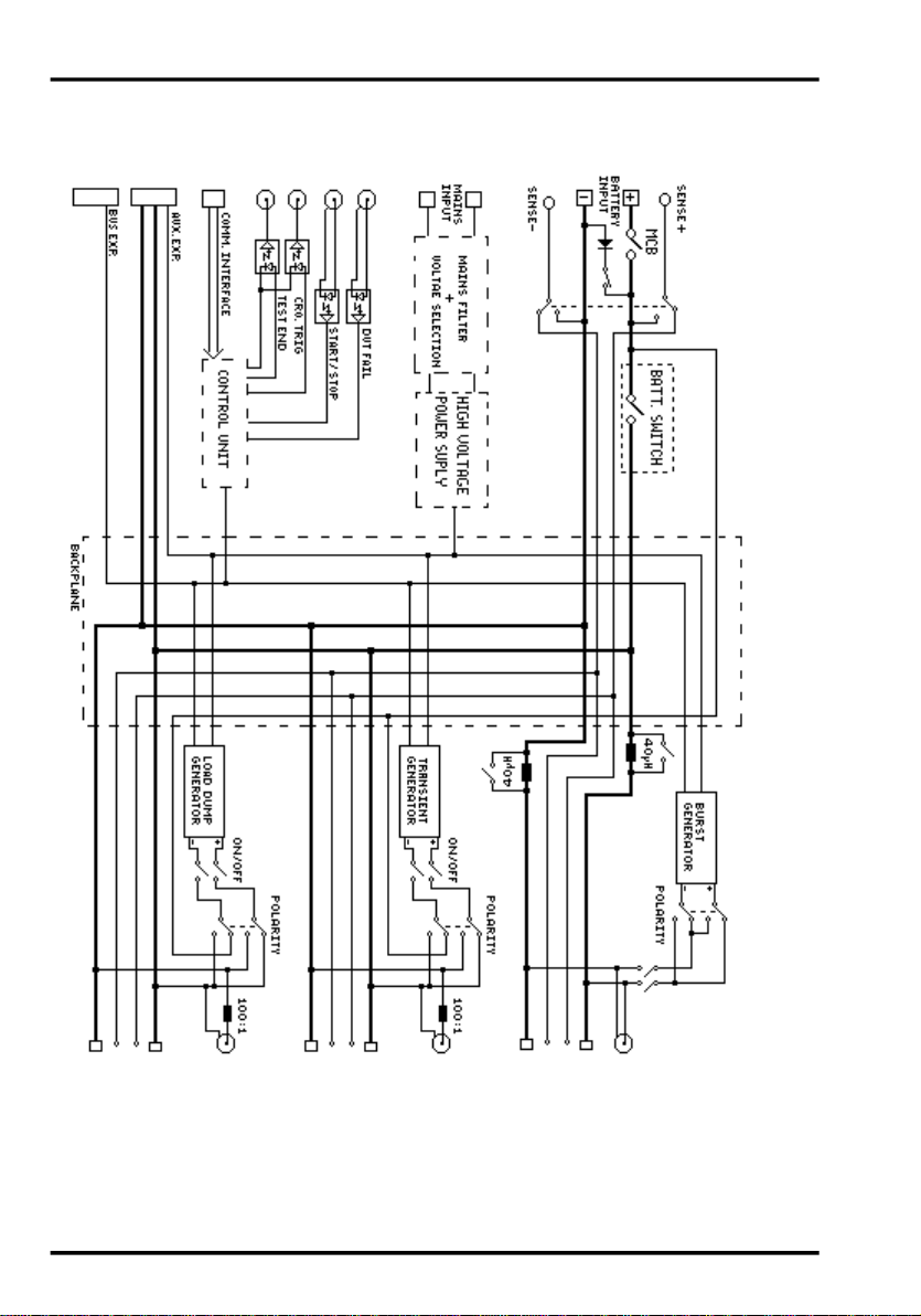
2.5 System Block Diagram
1-14

NSG 5000 SCHAFFNER INSTRUMENTS
2.6 External Connection of Pulse 4 Amplifiers (NSG5004/NSG5004A)
The Pulse 4/4c amplifiers (if supplied with the system) are housed in an
external chassis. This external chassis is controlled by the NSG5000
mainframe. The diagram below shows in conceptual form how the two units
are connected and interact.
The Pulse 4/4c unit is available in a 12.5 Amp and 25 Amp version. The NSG
5004/NSG5004A chassis is 19 inch rack mountable and is 6U high.
1-15
 Loading...