

Page 1

Installation Guide
Portable In-Transit
Tracking Unit
Page 2

Published August 2010
Part number 805-07190-901 Rev A
Documentation for Portable In-Transit Tracking Unit
Copyright © 2010 Savi Technology, Inc. All rights reserved. Unpublished - rights reserved
under the Copyright Laws of the United States.
Certain elements of this documentation as related to existing Vari-Trac technology are
Copyright © 2010 Vari-Trac Ltd., all rights reserved.
EchoPoint, Savi, Savi SensorTag, Savi SmartChain, Savi SmartStart, Savi Technology,
Savi’s Nested Visibility, SaviTag, SmartChain, the EchoPoint Logo, and the Savi Logo are
trademarks or registered trademarks of Savi Technology, Inc. in the United States and other
countries.
Information in this manual is subject to change without notice and does not represent a
commitment from the vendor. The software and/or databases described in this document
are furnished under a license agreement or nondisclosure agreement. The software and/or
databases may be used or copied only in accordance with the terms of the agreement. It is
against the law to copy the software on any medium except as specifically allowed in the
license or nondisclosure agreement.
THIS DOCUMENTATION CONTAINS CONFIDENTIAL INFORMATION AND
TRADE SECRETS OF SAVI TECHNOLOGY, INC. USE, DISCLOSURE OR
REPRODUCTION IS PROHIBITED WITHOUT THE PRIOR EXPRESS WRITTEN
PERMISSION OF SAVI TECHNOLOGY, INC.
U.S. GOVERNMENT RIGHTS
Use, duplication or disclosure by the U.S. government is subject to restrictions set forth in
the Savi Technology, Inc. license agreement and as provided in DFARS 227.7202-1(a) and
227.7202-3(a) (1995), DFARS 252.227-7013(c)(1)(ii) (OCT 1988), FAR 12.212(a) (1995),
FAR 52.227-19 or FAR 52.227-14 (ALT III), as applicable. Savi Technology, Inc.
Other product names mentioned in this guide may be trademarks or registered trademarks
of their respective owners and are hereby acknowledged.
Savi Technology.
351 E. Evelyn Avenue
Mountain View, CA 94041-1530
Phone: 1-650-316-4700
Facsimile: 1-650-316-4750
www.savi.com
Page 3

Contents
About the Portable In-Transit Tracking Unit . . . . . . . . . . . . . . . . 5
Integrated Architecture . . . . . . . . . . . . . . . . . . . . . . . . . . . . . . 6
Features. . . . . . . . . . . . . . . . . . . . . . . . . . . . . . . . . . . . . . . . . . 7
Setting Up the PITU . . . . . . . . . . . . . . . . . . . . . . . . . . . . . . . . . . 10
Verifying the PITU Pack Contents . . . . . . . . . . . . . . . . . . . . 10
Installing a GSM SIM Card . . . . . . . . . . . . . . . . . . . . . . . . . 11
Installing the Battery Power Pack. . . . . . . . . . . . . . . . . . . . . 16
Replacing the Battery Power Pack . . . . . . . . . . . . . . . . . . . . . . . 18
Issuing Operations Commands . . . . . . . . . . . . . . . . . . . . . . . . . . 21
LED Status Indicators. . . . . . . . . . . . . . . . . . . . . . . . . . . . . . 21
Checking Function Status . . . . . . . . . . . . . . . . . . . . . . . . . . . 21
Getting Ready to Communicate . . . . . . . . . . . . . . . . . . . . . . 22
Binding to a Tag and Starting Tracking . . . . . . . . . . . . . . . . 23
Stopping Tracking and Unbinding from a Tag. . . . . . . . . . . 24
1
Placing the PITU in Service Mode . . . . . . . . . . . . . . . . . . . . 24
Resetting the PITU . . . . . . . . . . . . . . . . . . . . . . . . . . . . . . . . 25
Mounting the PITU. . . . . . . . . . . . . . . . . . . . . . . . . . . . . . . . . . . 26
Attaching the Container Mounting Bracket . . . . . . . . . . . . . 26
Positioning the PITU. . . . . . . . . . . . . . . . . . . . . . . . . . . . . . . 28
Contacting Savi Global Support Services. . . . . . . . . . . . . . . 29
Specifications . . . . . . . . . . . . . . . . . . . . . . . . . . . . . . . . . . . . . . . 30
3
Page 4

4
Page 5

LED indicators
Command button
(marked G R C)
Container mounting bracket
PITU unit
About the Portable In-Transit Tracking Unit
The Portable In-Transit Tracking Unit (PITU) provides a complete
in-transit tracking solution by combining radio frequency identification
(RFID), global positioning system (GPS), and wide area communications
technology in a small self-contained integrated package. The PITU
augments an RFID network with continuous real time GPS position
information for tagged shipments and assets. The PITU electronically
binds to a Savi RFID tag and monitors the tag by obtaining its GPS
coordinates. The PITU is developed in partnership between Savi
Technology and Vari-Trac Ltd. and uses GPRS or SatCom to relay the
data to Savi SmartChain Server.
The PITU is GPS-based and uses GSM (global system for mobile
communications) cellular telecommunications and Iridium’s Short Burst
Data (SBD) satellite data service for data transfer. The system also has
other sensors, inputs, and outputs to interact with the operational
environment. This includes a 3 axis motion sensor. The PITU is utilizes a
non-rechargeable
a 10-year shelf life.
, field replaceable Lithium Thionyl battery pack that has
PITU Model# PITU-0001-B front view with container mounting bracket
5
Page 6
Portable In-Transit Tracking Unit Installation Guide
Quick Reference Guide
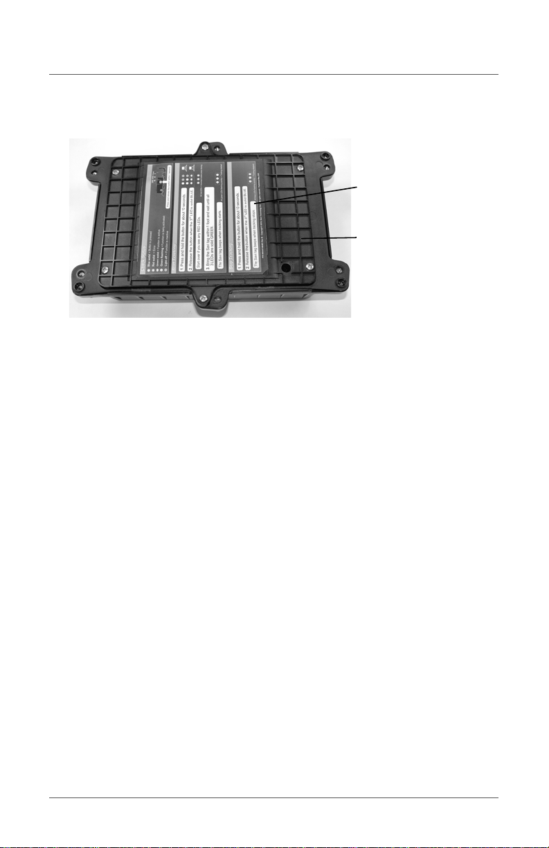
Battery hatch cover
PITU Model# PITU-0001-B rear view
Integrated Architecture
The PITU consists of the following key components in a small hardened
enclosure:
• Vari-Trac GPS tracking module with GPRS communications
• Iridium satellite SBD module
• Savi RFID mobile reader (SMR-650)
• GPS, GSM, and satellite antennas
• Power control unit and Intelligent RS-232 I/O multiplexer
The PITU can be used anywhere in the global supply chain including
harsh environments common in global military supply chains. Its small
size makes it easy to handle when you mount and lock it on a standard
ISO container or other conveyance. The PITU operates completely using
internal battery power.
6
Page 7

Features
Features
• Securely attaches anywhere in the supply chain
• Easily associates with RFID tags on the shipment
• Delivers GPS location updates to the server in real time using the
lowest cost communications network available
• Relays security and sensor alarms from the associated tag
• Alarms if the shipment deviates from the expected route or travel path
• Alarms if the associated tag disappears or if the device is removed
while en-route
• Easily disassociated from the RFID tag and removed from the
shipment in authorized areas of the supply chain
• Weather tight, IP67-compliant standard external enclosure
• All components and antennas are completely enclosed
• Fits between container locking bars so the device is safe in a stacked
environment
• Strong magnets hold device on the container during journey
• Standard metal container locking bolt secures device to bars
• Monitoring automatically starts when the container moves into a
tracked region
7
Page 8
Portable In-Transit Tracking Unit Installation Guide
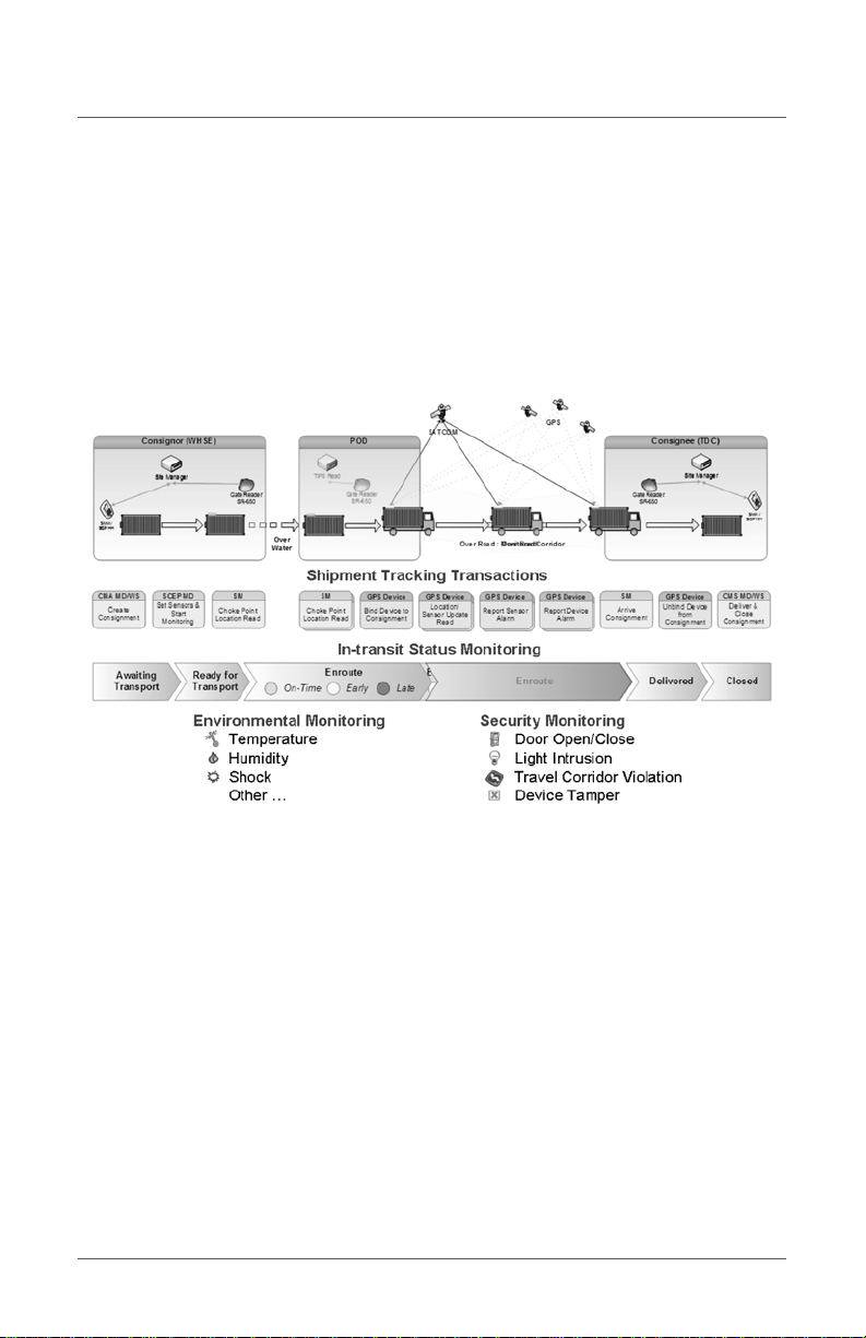
Extended In-Transit Tracking Workflow
The PITU provides an environmental and security shipment tracking
solution for times when the shipment is between RFID monitored areas.
As shown in the following diagram, the PITU bridges monitoring
between the point of delivery and the consignee.
8
Page 9
Features
Quick Reference
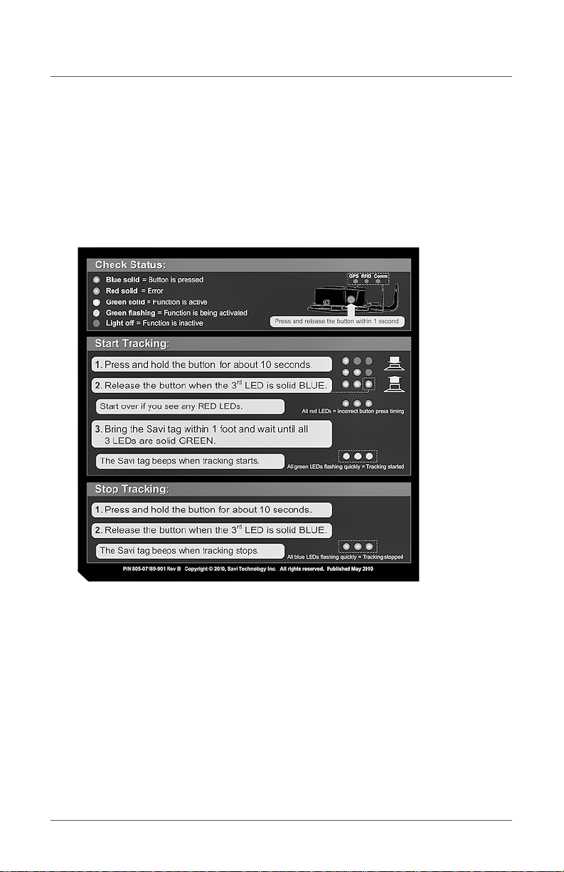
The following quick reference appears on the back of the PITU. It
provides a brief instruction on how to use the PITU operational
commands. See “Issuing Operations Commands” on page 21 for detailed
command instructions.
Note: This equipment complies with FCC radiation exposure limits set forth
for an uncontrolled environment. This equipment should be installed
and operated with a minimum distance of 20 cm between the radiator
and your body. This transmitter must not be co-located or operated
in conjunction with any other antenna or transmitter.
9
Page 10

Portable In-Transit Tracking Unit Installation Guide
Setting Up the PITU
To set up and use the PITU, you must acquire and register an activated
SIM card, install the SIM card in the PITU, install the battery pack in the
PITU, and issue the commands to start tracking.
Prerequisites
• Registered activated SIM card
Verifying the PITU Pack Contents
Make sure you PITU shipping package contains these items.
• PITU unit
• Container mounting plate
• Battery pack
• Torx key screws (10 ea.)
• X20 Torx key screwdriver
• Documents including this guide, Packing List, Statement of
Certification, and Savi Customer Service leaflet
10
Page 11
Torx key screwdriver
Torx screws
Torx screws
Installing a GSM SIM Card
Installing a GSM SIM Card
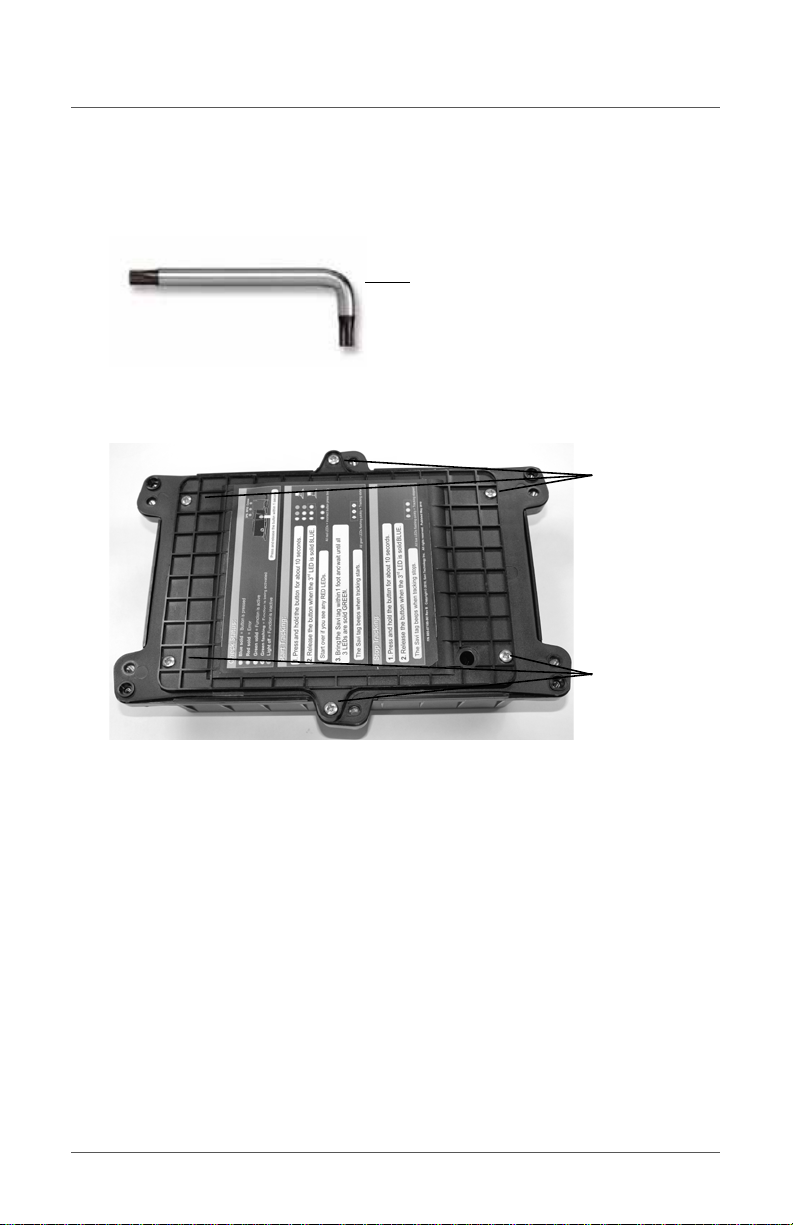
1. Locate the Torx key screwdriver included with the battery pack.
2. Using the Torx key screwdriver, unscrew and set aside the 6 screws
securing the battery hatch cover at the back of the PITU.
11
Page 12
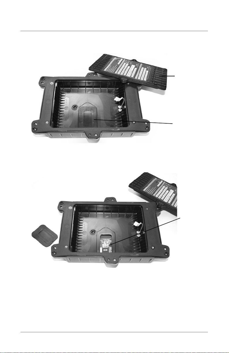
Portable In-Transit Tracking Unit Installation Guide
Battery hatch
Plastic cover
cover
for SIM card
SIM card
holder
3. Remove the battery hatch cover to expose the inner compartment and
the hard plastic cover for the SIM card holder recess.
4. Remove the hard plastic cover to expose the SIM card holder and
verify there is no SIM card installed.
12
Page 13
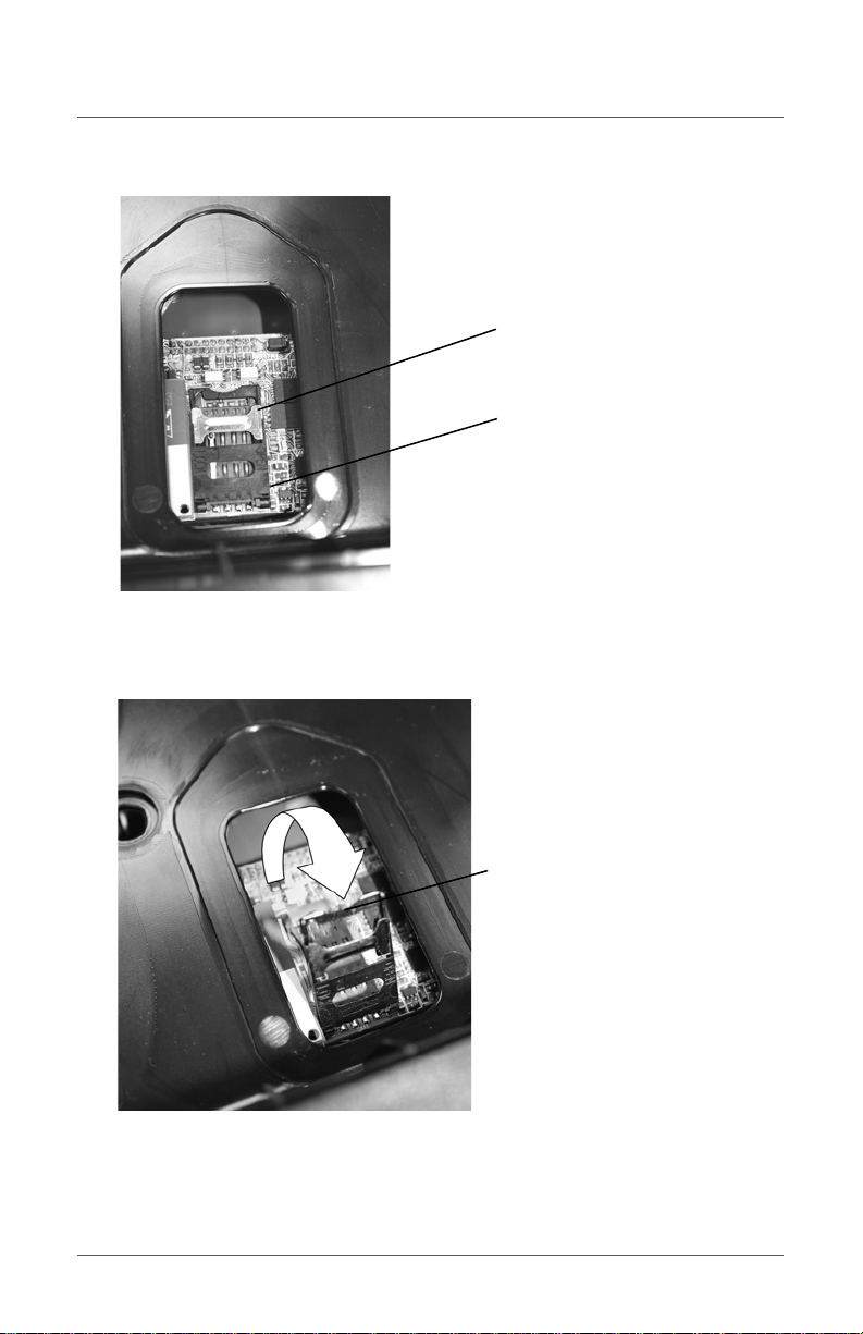
I-shaped
retaining clip
SIM card holder
SIM card
holder raised
Installing a GSM SIM Card
5. Slide the silver I-shaped holder retaining clip toward the outside edge
of the PITU to unlock the SIM card holder.
6. Raise the edge of the SIM card holder closest to the center of the PITU.
13
Page 14
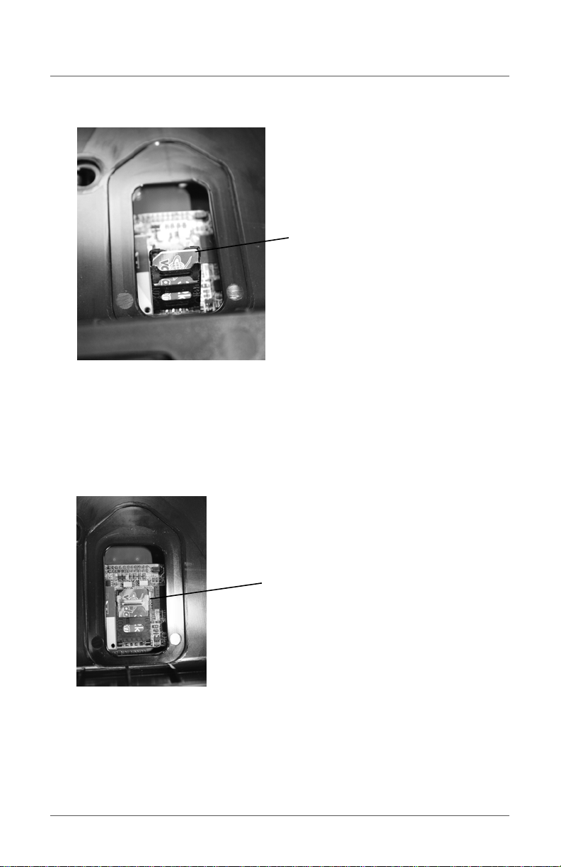
Portable In-Transit Tracking Unit Installation Guide
SIM card
inserted
SIM card
locked down
7. Insert the SIM card in the correct orientation as shown above.
NOTE: The cut-off corner of the SIM card is at the upper-left in the pic ture
above.
If a SIM card is pre-installed, remove it and install the SIM card you
activated.
8. Lower the SIM card holder and slide the silver I-shaped holder
retaining clip toward the center of the PITU to lock the SIM card
holder in place.
14
Page 15

Installing a GSM SIM Card
9. Realign and press the hard plastic cover for the SIM card holder recess
into place.
NOTE: The wider edge of the cover is toward the center of the PITU. The
cover only fits in one direction.
10.
Proceed to installing the battery power pack.
15
Page 16
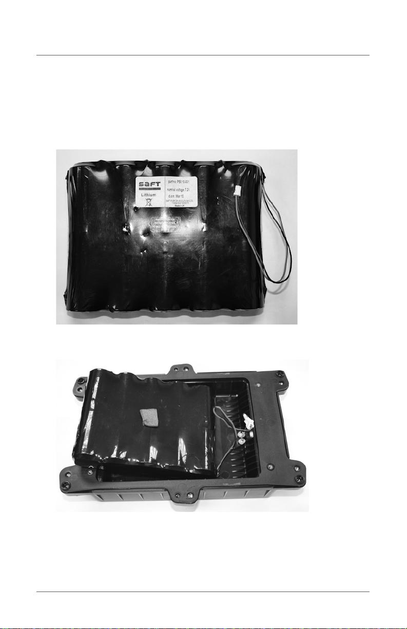
Portable In-Transit Tracking Unit Installation Guide
Installing the Battery Power Pack
Use only the supplied battery pack. See also “Replacing the Battery
Power Pack” on page 18.
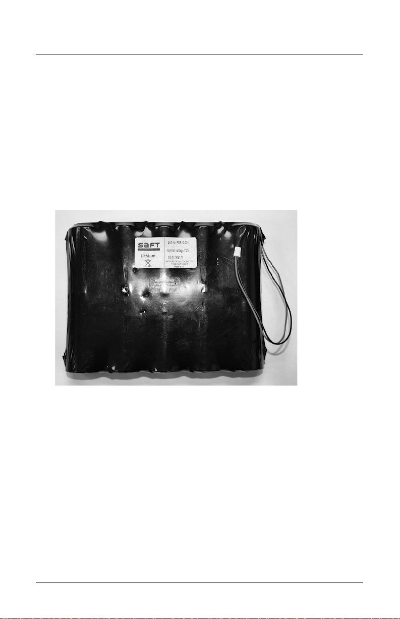
1. Remove the power pack from all shipping materials.
2. Partially insert the battery power pack into the PITU battery
compartment as shown.
16
Page 17

Installing the Battery Power Pack
The connector from the battery pack is at the same side as the battery
connector inside the PITU battery compartment.
3. Align and connect the cable end from the battery pack to the cable end
protruding from the inside of the battery compartment. Press the two
ends together until they click.
4. Lower the battery power pack completely and seat it in the
compartment ensuring the connector cable is clear of the opening.
5. Replace the battery hatch cover and re-insert the 6 Torx screws.
6. Use the Torx screwdriver to evenly re-screw all 6 screws on the cover
ensuring the hatch is sealed.
17
Page 18
Portable In-Transit Tracking Unit Installation Guide
Replacing the Battery Power Pack
WARNING: Use only the supplied battery power pack. There is risk of
explosion if you replace the battery pack with an incorrect type.
Dispose of used battery packs in accordance with local safety standards
and the instructions in step 4 on page -19.
1.
Remove the power pack from all shipping materials.
2. Use the Torx key screwdriver to unscrew and set aside the 6 screws
securing the battery hatch cover at the back of the PITU.
3. Disconnect the cable end from the battery pack and the cable end
protruding from the inside of the battery compartment.
18
Page 19
Installing the Battery Power Pack
4. Remove the used battery pack from the battery compartment.
WARNING: Disposal of spent battery packs in the European Union must
conform to EC Directives 91/157/EEC of 18/03/91 and 98/86/EEC of
04/10/93 as per each independent member country.
Disposal of spent battery packs in the United States mus t conform to EP A
Disposal Code D003 UN# 3090 Waste Lithium Batteries.
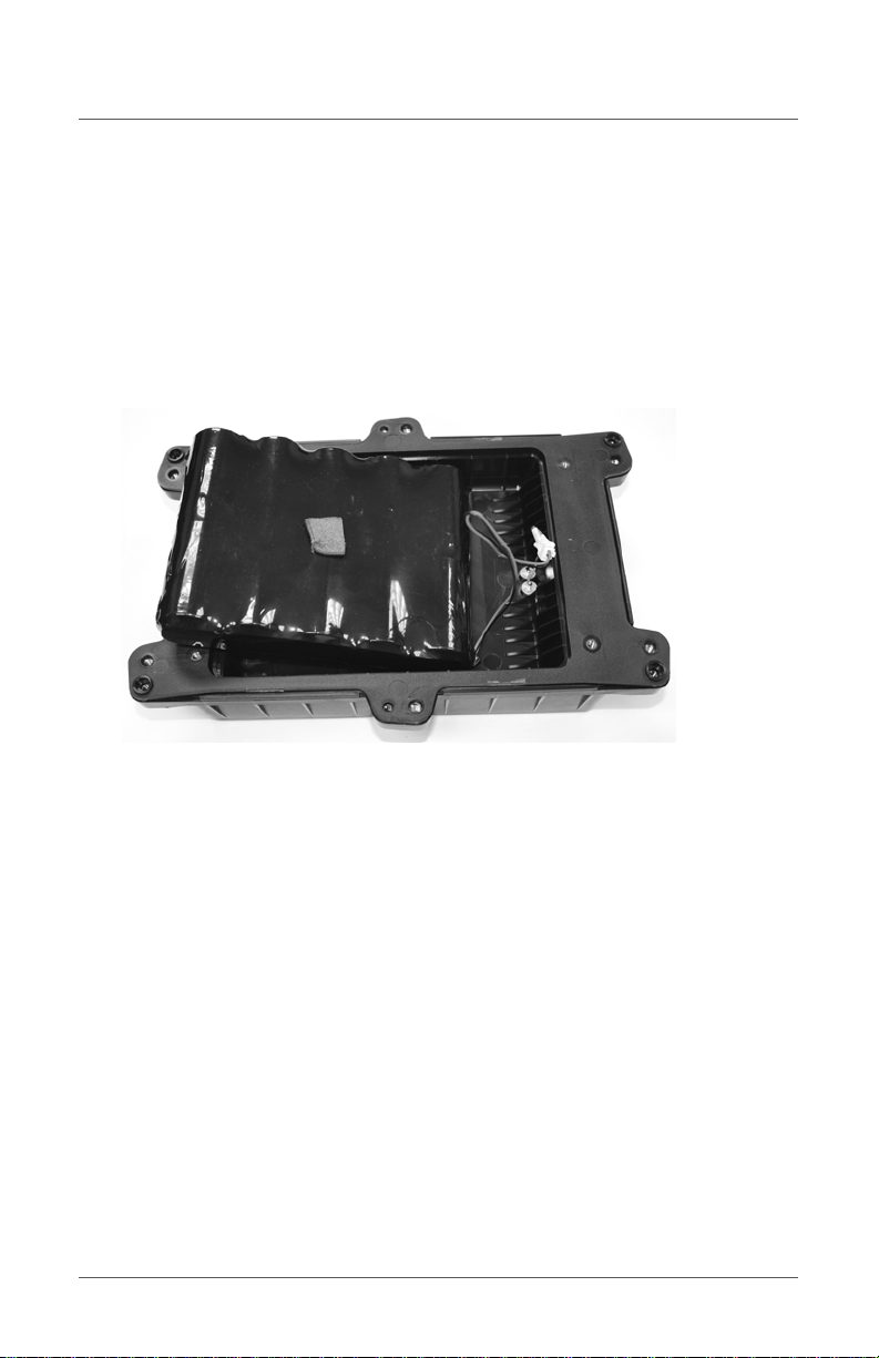
5.
Partially insert the new battery power pack into the PITU battery
compartment as shown.
The connector from the battery pack is at the same side as the battery
connector inside the PITU battery compartment.
19
Page 20

Portable In-Transit Tracking Unit Installation Guide
6. Align and connect the cable end from the battery pack to the cable end
protruding from the inside of the battery compartment. Press the two
ends together until they click.
7. Lower the battery power pack completely and seat it in the
compartment ensuring the connector cable is clear of the opening.
8. Replace the battery hatch cover and re-insert the 6 Torx screws.
NOTE: The ha tc h co ver onl y fits in one d irec ti on.
9.
Use the Torx screwdriver to evenly re-screw all 6 screws on the cover
ensuring the hatch is sealed.
20
Page 21

Issuing Operations Commands
LED Status Indicators
LED
The three LEDs embedded in the top of the PITU provide status
information about the GPS, RFID, and satellite communication
components. Each LED is marked by a letter representing the function.
G identifies the GPS function, R identifies the RFID module, and C
indicates Communications. The color and action of the LED show the
status:
• Blue LED - operation button is pressed down
• Red LED - error/condition unknown
• Green LED - function is active
• LED off - function is inactive
• LED solid on - function is active in ready mode
• LED flashing - function is being activated
Status Indicators
Checking Function Status
To check the status of the PITU functions, press the button once for less
than 1 second.
The Comms LED lights blue when you press the button, then lights green
briefly. Otherwise, all 3 LEDs light red to indicate an error.
The positive status response is all 3 LEDs will flash fast green or blue.
21
Page 22

Portable In-Transit Tracking Unit Installation Guide
Getting Ready to Communicate
NOTE: You can perform a get ready command to make sure all
communications links are working before you mount the PITU or are
near a tag you want to bind with and track.
The default state of the PITU is inactive or sleeping to conserve battery
life. While in the inactive state, the PITU does not monitor tags, send
tracking messages, or respond to commands. You initiate a get ready
command to wake up the PITU and put it in an active state.
Press and release the button 3 consecutive times for less than 1 second
each. Each release should not be more than 1 second between presses.
The Comms blue LED lights on the first press, the RFID blue LED lights
on the second press, and the GPS blue LED on the third press. The RFID
LED briefly lights green. Otherwise, all 3 LEDs light red to indicate an
error.
A positive get ready response is all 3 LEDs will flash fast green or blue.
Note that the LEDs will be blank for a few seconds while the main system
boots up. The LEDs automatically update upon a change in the GPS,
RFID, or Comms connection status.
NOTE: GPS failure may be caused by GPS hardware failure or insufficient
signal coverage resulting in a time out.
RFID being ready means that the main system established succes sful
communications with the RFID mobile reader contained wi thin the PITU.
Comms being ready means that a login to back office was successful with
any medium available such as GPRS, satellite, and so forth.
22
Page 23

Binding to a Tag and Starting Tracking
Binding to a Tag and Starting Tracking
NOTE: You can perform a get ready command to make sure all
communications links are working before you mount the PITU or are
near a tag you want to bind with and track. See “Getting Ready to
Communicate” on page 22.
After obtaining the function status, you can initiate a command to bind
with a tag and start tracking. Once all functions are ready, the PITU uses
RFID to communicate with the Savi tag and beeps the tag closest to the
unit that will be used for the tracking operation. After a successful RFID
scan, the PITU uses GPRS or SatCom to transmit the tag data and the
current GPS coordinates to SmartChain Server.
When start tracking is active, the PITU wakes up at a predetermined
interval, communicates with the Savi tag, reads the tag’s current GPS
coordinates, and transmits all data to SmartChain Server.
T o bind with a tag and start tracking, press and hold down the button until
all 3 lights are on, then release immediately. If you continue to hold down
the button, the PITU will initiate a reset and you will have to start over
from the beginning.
The Comms blue LED lights after holding the button for 2 seconds, the
RFID blue LED lights after holding the button for 4 seconds, and the GPS
blue LED lights after holding the button for 6 seconds.
While a function such as GPS, RFID, and GPRS or SatCom is getting
ready, the corresponding green LED flashes. Solid green LEDs indicate
when the corresponding function is ready. Otherwise, all 3 LEDs light red
to indicate an error.
3 fast flashing green LEDs indicate start tracking is successful.
23
Page 24

Portable In-Transit Tracking Unit Installation Guide
Stopping Tracking and Unbinding from a Tag
After verifying the function status, you can initiate a command to stop
tracking and unbind the PITU from a tag.
To stop tracking and unbind from a tag, press and hold down the bu tton
until all 3 lights are on, then release immediately. If you continue to hold
down the button, the PITU will initiate a reset and you will have to start
over from the beginning.
The Comms blue LED lights after holding the button for 2 seconds, the
RFID blue LED lights after holding the button for 4 seconds, and the GPS
blue LED lights after holding the button for 6 seconds.
While a function such as GPS, RFID, and GPRS or SatCom is getting
ready, the corresponding green LED flashes. Solid green LEDs indicate
when the corresponding function is ready. Otherwise, all 3 LEDs light red
to indicate an error.
3 fast flashing blue LEDs indicate stop tracking is successful.
Placing the PITU in Service Mode
NOTE: A reset is similar to service mode but a reset causes the PITU to fall
back to the previous state.
Service mode is a maintenance or debugging mode that is intended to be
used only during testing. In service mode the GPS is active, and GPRS or
SatCom will periodically connect, but the RFID reader is not bound to a
tag.
To put the PITU into service mode, press and hold the button for at least
26 seconds.
The Comms blue LED lights after holding the button for 2 seconds, the
RFID blue LED lights after holding the button for 4 seconds, and the GPS
blue LED lights after holding the button for 6 seconds.
24
Page 25

Resetting the PITU
Next the blue LEDs flash sequentially two times. The blue LEDs flash
sequentially two more times, each progressively faster. All 3 LEDs flash
green briefly. Otherwise, all 3 LEDs light red to indi cate an error. Wait 10
seconds after releasing the button, then press the button for less than 1
second to put the unit into service mode.
When the unit goes out of service mode all 3 LEDs flash green and then
flash red.
Resetting the PITU
NOTE: A reset is similar to service mode but a reset causes the PITU to
fall back to the previous state.
To reset the PITU, press and hold down the button for at least 26 seconds.
The Comms blue LED lights after holding the button for 2 seconds, the
RFID blue LED lights after holding the button for 4 seconds, and the GPS
blue LED lights after holding the button for 6 seconds.
Next the blue LEDs flash sequentially two times. The blue LEDs flash
sequentially two more times, each progressively faster. Otherwise, all 3
LEDs light red to indicate an error. The unit completes resetting in
approximately 60 seconds quickly green and then quickly red.
25
Page 26
Portable In-Transit Tracking Unit Installation Guide
Container mount
Magnet
locations
Top
Bottom
Mounting the PITU
Attaching the Container Mounting Bracket
WARNING: All magnets except those that are steel and rubberized are
brittle and may break or chip if allowed to fall onto a hard surface, or if
they slap against each other or a ferrous surface.
Keep very strong magnets away from small children. More powerful
magnets may pinch fingers. It is safest to slide strong magnets together
or apart.
Keep magnets away from credit cards, audio tapes, video tapes, and
computer disks. CDs are not affected. Strong magnets can be harmful to
computer monitors and television screens. Savi will not be held
responsible for any damage or magnetic data lost through accident with,
or misuse of, these magnets.
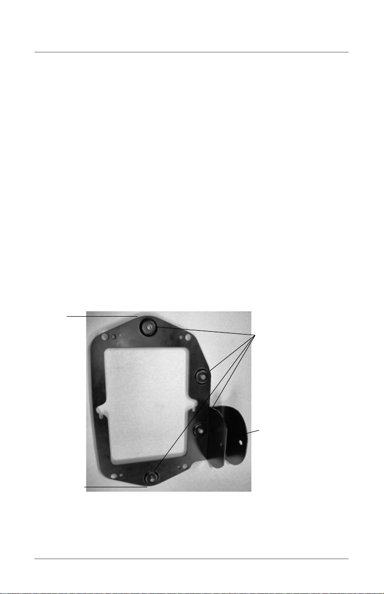
1.
Remove the container mount from all shipping materials.
26
Page 27
Magnets
Command
button
Locking bar clamp
Mounting Torx screws
Attaching the Container Mounting Bracket
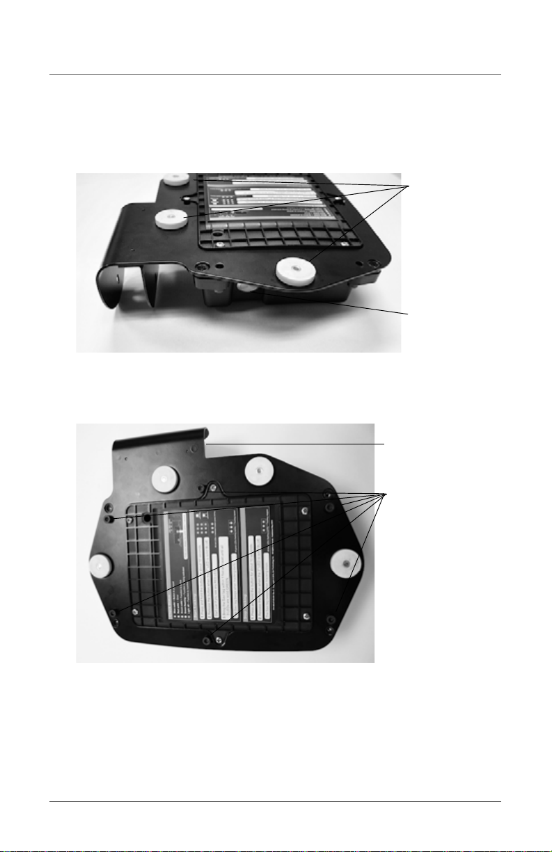
2. Place the PITU face down on a flat surface with the large command
button toward you.
3. Place the mounting bracket onto the back of the PITU ensuring the
locking bar clamp is face down on the left side.
4. Align and insert the 6 Torx screws provided through the mounting
bracket holes into the holes of the PITU.
5. Use the Torx key screwdriver to evenly secure the screws in place.
27
Page 28
Portable In-Transit Tracking Unit Installation Guide
PITU
ST-654 RFID tag
to be monitored
Positioning the PITU
Mount the PITU to the container as pictured below.
• Ensure the PITU is located above the RFID tag it will be bound to
• Mount the PITU as high as possible on the container rear door
• Mount the PITU between the container locking bars where it is safe in
a stacked environment
• Secure the device with the container mounting bolt
28
Page 29

Contacting Savi Global Support Services
Contacting Savi Global Support
Services
Savi Global Support Services operates 24x7. Access to 24x7 support
depends on your Savi support plan.
For product information, including firmware updates:
•Go to www.savi.com
• Send an email to [email protected].
• Call 1-888-994-7284 (North America only) or 1-650-316-4760.
When you contact Savi Global Support Services by telephone or email,
have the following information available:
• Contact information (company name, your name, email, and phone
number)
• Problem description
• Product name/model
• Product/software version
• Serial number or license information
and click SAVI SUPPORT.
29
Page 30

Portable In-Transit Tracking Unit Installation Guide
Specifications
Model Number PITU-0001-B
Physical
Characteristics
Environmental Temperatur e: Operating: -20°C to +60°C ambient;
Iridium SBD Module Frequency: 1616 MHz to 1626.5 MHz
GSM/GPRS Module Frequency: 850/900/1800/1900 MHz
Dimensions: 28.7 cm (11.30 in) x 19.5 cm (7.68 in) x
6.6 cm (2.60 in) excluding mount
Weight: 1700 grams (3.97 lb)
Color: Black
Storage -20°C to +60°C ambient
Humidity: 5% to 95% non-condensing
Altitude: Max is 12,500 m (7.76 miles)
Vibration and shock: MIL-STD-810E
Enclosure: IP67 compliant
Duplexing Method: TDD (Time Domain Duplex)
Oscillator Stability: ± 1.5 ppm
Input/Output Impedance: 50 Ohm
Multiplexing Method: TDMA/FDMA
Max. transmit power: 1.6 W
Internet Protocols: TCP/IP, UDP
GPRS: Class 10: max. 86 kbps (DL)
SMS: Point-to-point MO and MT, Text and PDU
mode
Input/Output Impedance: 50 Ohm
Output Power: Class 4 (2 W) for EGSM 850/900,
Class 1 (1 W) for GSM 1800/1900
30
Page 31

Contacting Savi Global Support Services
GPS Module Processor: SiRF III GSC3e/LP
Tracking capability: 20 satellites simultaneously
Horizontal accuracy: 2.2 m (CEP), 5.5 m 2dRMS
PPS accuracy: typically better than 1 s
Acquisition performance: -140 dBm = hot start TTFF
<1 s, warm start TTFF <49 s, cold start TTFF <52 s
Savi UHF Receiver
(uplink)
Savi UHF Transmitter
(downlink)
Power Battery type: 10.8 volt lithium-thionyl chloride
Approval R&TTE 1999/5/EC, FCC Part 15
UHF Frequency: 433.92 MHz
UHF Range: Up to 200 feet (61 m) with the SaviTag
600/410 series
Modulation: FSK, deviation +/- 50KHz
Data Rate: 27.8 Kbps, 50% duty cycle
Data Coding: Manchester (EBCS/EP) and PCM (BCS)
UHF Air Protocol: EchoPoint Air Protocol 2.1
(two-way UHF commands; Seal extension
commands) BCS/EBCS Commands
Receiver sensitivity: -100 dBM
UHF Antenna: 50 Ohms matched external helical
antenna
Max. Transmit Power: 0.6 mW
(Li-SOCl2) (55 Ah)
Battery life: Approximately 4 years at 4 polls per day;
10-year shelf life
31
Page 32

Portable In-Transit Tracking Unit Installation Guide
32
 Loading...