

TES ELECTRONIC SOLUTIONS 9008251, 9008323 Users Manual
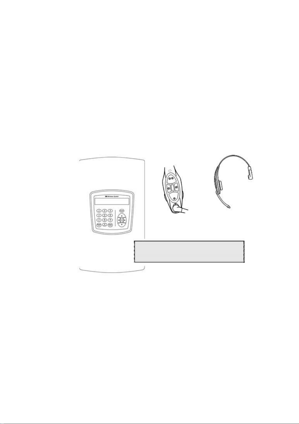
3M™ Wireless Communication System, Model XT-1
Operating Instructions
Rev 1.0
© 3M 2007 November
01>Drivethru Volume< 04 Registration
02>Monitor Volume< 05 Noise Reduction
03>Night Volume< 06 Set Time & Date
:SYSTEM MENU

Table of Contents
Table of Contents
OVERVIEW ............................................................................................................................................ . 7
Safety Information ............................................................................................................................... 7
Safety Rules .................................................................................................................................... 7
Intended Use ................................................................................................................................... 7
Signal Words ................................................................................................................................... 7
Product Safety Labels ................................................................................................................... . 7
System Warnings ........................................................................................................................... 8
Other Conventions .............................................................................................................................. 8
Important Notes and Notes............................................................................................................. 8
FCC Information................................................................................................................................... 8
CONFIGURATION .................................................................................................................................. 9
Enter Configuration Mode.................................................................................................................... 9
Navigating the Base Station Display .................................................................................................. 9
Interpreting Display Information ..................................................................................................... 9
Buttons........................................................................................................................................... 10
Connecting to the Ethernet Port ....................................................................................................... 11
Network Setup .............................................................................................................................. 11
Logging into the Base Station with a Computer .......................................................................... 11
Change Basic Volume Settings......................................................................................................... 12
Inbound Microphone Volume ....................................................................................................... 12
Outbound Talk Volume ................................................................................................................ 12
Vehicle Alert Volume .................................................................................................................... 12
Outbound Greeter Message Volume........................................................................................... 13
Change the Monitor Volume ............................................................................................................. 13
Inbound Listen .............................................................................................................................. 13
Outbound Talk .............................................................................................................................. 13
Vehicle Present ............................................................................................................................. 14
Vehicle Approach ......................................................................................................................... 14
Page Messages ............................................................................................................................ 14
Greeter Messages ........................................................................................................................ 14
Change the Night Volume ................................................................................................................ 15
Registering Headsets ........................................................................................................................ 15
Add Headsets ............................................................................................................................... 15
Remove Headsets ........................................................................................................................ 16
List All Headsets ........................................................................................................................... 16
Resetting Inactive Days ................................................................................................................ 16
Checking Headset Software Revision ......................................................................................... 16
Change Noise Reduction Level ........................................................................................................ 16
Inbound Microphone Noise Reduction Level............................................................................... 16
Acoustic Echo Canceller............................................................................................................... 17
Set System Date and Time... ............................................................................................................ 17
Change Global Settings .................................................................................................................... 17
Text and Audio Prompts Language ............................................................................................. 17
Drive Thru Audio Duplex Mode .................................................................................................... 18
Page Channel Heard by Order Taker.......................................................................................... 18
Number of Base Stations at this Site............................................................................................ 18
Store is Now Closed Prompt ........................................................................................................ 19
Pull Ahead Prompt......................................................................................................................... 19
Customer Order Point Prompt Language ................................................................................... 19
Order Point TALK with No Vehicle .............................................................................................. 19
Order Takers in Cross Lane Mode .............................................................................................. 19
3M™ Wireless Communication System, Model XT-1: Operating Instructions Rev 1.0 © 3M 2007 November
Page 3 of 48

Table of Contents
Detector Type ................................................................................................................................ 20
Order Taking Modes Setup ............................................................................................................... 20
Change Site Scheduling..................................................................................................................... 20
Regular Site Schedule .................................................................................................................. 21
Holiday/Exception Schedule ......................................................................................................... 21
Change Site Information ................................................................................................................... 21
Change Self Monitoring ..................................................................................................................... 21
Change Passcodes ........................................................................................................................... 22
User Passcodes ............................................................................................................................ 22
Installer Setup .................................................................................................................................... 22
Load Installation Settings .............................................................................................................. 22
Save Installation Settings ............................................................................................................. 23
Factory Setup (Restore Factory Defaults)......................................................................................... 23
Create and Load Templates ............................................................................................................. 23
Reboot System................................................................................................................................... 23
Check the Revision Levels ................................................................................................................ 23
Activate the Backup Intercom ........................................................................................................... 24
OPERATION ... ...................................................................................................................................... 25
Headsets ............................................................................................................................................ 25
Overview ... .................................................................................................................................... 25
Component Identification and Description ................................................................................................ 25
Fitting the Headset ........................................................................................................................ 26
Replace the Battery ...................................................................................................................... 26
Out of Range ................................................................................................................................. 27
Cleaning......................................................................................................................................... 27
Base Station Setup ............................................................................................................................ 28
Navigating in the Base Station in Run Mode ............................................................................................ 28
Change Order Taking Mode ......................................................................................................... 28
Explanation of Order Taking Modes ......................................................................................................... 29
Listen: Auto, Manual, and Always On .................................................................................................. 29
Talk: Manual Latching, Push to Talk, Automatic ................................................................................. 29
Automatic Standby: On and Off ........................................................................................................... 30
Vehicle Detector: Presence or Ignored ................................................................................................ 30
Order Point: Used or Not Used ............................................................................................................ 30
Which Order Taking Mode to Select ........................................................................................................ 30
Change Lane Mode ...................................................................................................................... 30
Split Lane ................................................................................................................................................... 31
Cross Lane ................................................................................................................................................ 31
Change Volume Mode .................................................................................................................. 31
MAINTENANCE .................................................................................................................................... 33
Headset ............................................................................................................................................. . 33
Replacing the Ear and Headband Pads ...................................................................................... 33
Battery Charger.................................................................................................................................. 33
Location ......................................................................................................................................... 33
Cleaning the Contacts .................................................................................................................. 33
Batteries.............................................................................................................................................. 34
Care, Handling and Storage ......................................................................................................... 34
Low Battery Message ................................................................................................................... 34
Charging Batteries ........................................................................................................................ 34
Disposing of Batteries.................................................................................................................... 34
Making Sure Batteries are Ready for Use ................................................................................... 35
Important Information about XT-1 Rechargeable Batteries.......................................................... 35
3M™ Wireless Communication System, Model XT-1: Operating Instructions Rev 1.0 © 3M 2007 November
Page 4 of 48

Table of Contents
TROUBLESHOOTING ......................................................................................................................... 37
General Troubleshooting .................................................................................................................. 37
Battery and Battery Charger Troubleshooting ................................................................................. 38
APPENDIX: BASE STATION SPECIFICATIONS .............................................................................. 39
Physical ............................................................................................................................................. 39
Electrical ............................................................................................................................................ 39
Functional........................................................................................................................................... 39
APPENDIX: GREETER MODULE ....................................................................................................... 41
Greeter Setup .................................................................................................................................... 41
Enter the Greeter Configuration Menu ........................................................................................ 41
Play Greeter Message .................................................................................................................. 41
Select Specific Greeter Messages .............................................................................................. 41
Change Playback Mode ............................................................................................................... 41
Change Playback Delay Time ..................................................................................................... 42
Set Greeter Playback through Headsets ..................................................................................... 42
Set Playback through Monitor ...................................................................................................... 42
Turn on Tone to Headsets During Greeter Playback ................................................................. 43
Turn on Restaurant Closed Playback Message ......................................................................... 43
Turn on External Detector Playback Message ........................................................................... 43
APPENDIX: FCC and Safety Statement ... .......................................................................................... 44
Greeter Setup .................................................................................................................................... 41
Enter the Greeter Configuration Menu ........................................................................................ 41
Play Greeter Message .................................................................................................................. 41
Select Specific Greeter Messages .............................................................................................. 41
Change Playback Mode ............................................................................................................... 41
Change Playback Delay Time ..................................................................................................... 42
Set Greeter Playback through Headsets ..................................................................................... 42
Set Playback through Monitor ...................................................................................................... 42
Turn on Tone to Headsets During Greeter Playback ................................................................. 43
Turn on Restaurant Closed Playback Message ......................................................................... 43
Turn on External Detector Playback Message ........................................................................... 43
INDEX .................................................................................................................................................... 45
3M™ Wireless Communication System, Model XT-1: Operating Instructions Rev 1.0 © 3M 2007 November
Page 5 of 48

Table of Contents
3M™ Wireless Communication System, Model XT-1: Operating Instructions Rev 1.0 © 3M 2007 November
Page 6 of 48
Safety Information
Safety Rules
Intended Use
Overview
Overview
Read, understand, and follow all safety information contained in these
instructions prior to installation & operation of the 3M Headset Intercom
System, Model XT-1. Failure to follow all instructions listed could result in
electrical shock, fire and/or other personal injury. Retain these instructions for
future reference.
The 3M Headset Intercom System Model XT-1 is intended for use to provide 2way radio-frequency audio communication in quick service drive-through
restaurants and convenience stores.
The system must be installed as specified in the Model XT-1 Installation
Instructions and operated as specified in Model XT-1 Operating Instructions in
quick service drive-through restaurants and convenience stores. It has not been
evaluated for other uses or locations.
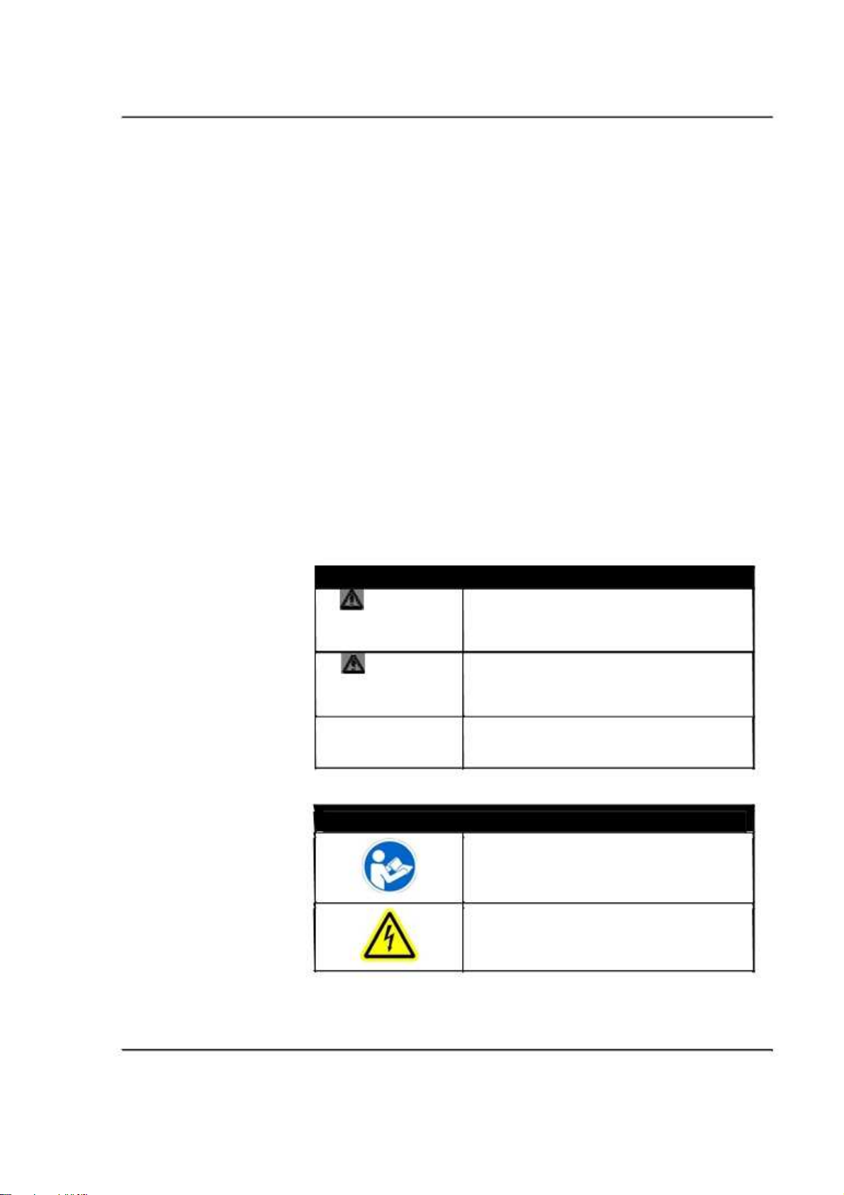
Signal Words
WARNING:
CAUTION:
CAUTION:
Explanation of Signal Word Consequences
Indicates a potentially hazardous situation, which, if
not avoided, could result in death or serious injury
and/or property damage.
Indicates a potentially hazardous situation, which, if not
avoided, may result in minor or moderate injury and/or
property damage.
Indicates a potentially hazardous situation, which, if not
avoided, may result in property damage.
Product Safety Labels
Explanation of Product Safety Labels
Attention: Read accompanying documentation
3M™ Wireless Communication System, Model XT-1: Operating Instructions Rev 1.0 © 3M 2007 November
Warning: Risk of Electric Shock
Page 7 of 48
Overview
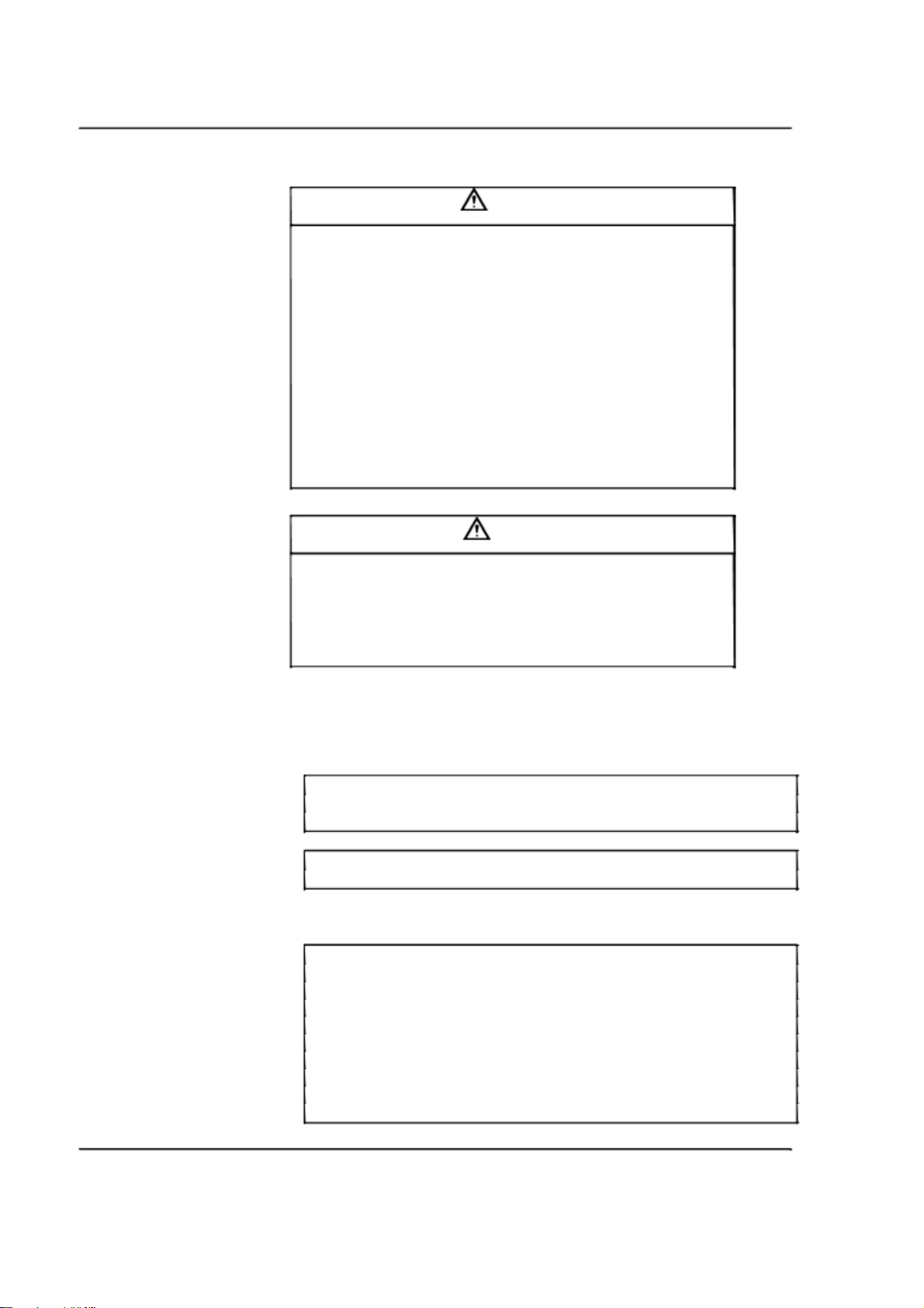
System Warnings
To reduce the risks associated with hazardous voltage:
•
Disconnect power to the receptacle before installing or removing the
Base Station Power Supply. When removing receptacle cover screw,
cover may fall across plug pins or receptacle may become displaced. Use
only with duplex receptacle having center screw. Secure unit in place by
receptacle cover screw.
•
If power supply is supplied with a grounding pin, connect directly to a
To reduce the risks associated fire & property damage:
grounding receptacle - 3 prong.
•
Do not open, crush, expose to heat above 200 °F or incinerate the
battery.
•
Always replace batteries, battery chargers and power supplies with
3M approved units acceptable for use in this system to avoid system
function & safety concerns.
WARNING
CAUTION
To reduce the risks associated with environmental contamination due to battery
pack & to lead in the solder:
•
Dispose of batteries, power supplies, battery charger and base
station in accordance with federal, state & local requirements. If
preferred, return these components to 3M Service Center for
disposal.
Other Conventions
Important Notes and Notes
Important Note:
It is strongly recommended that you pay attention to information inside of an
“Important Note:” box.
Note:
You may find information inside of a “Note:” box helpful.
FCC Information
Note:
This equipment has been tested and found to comply with the limits for a
Class A digital device, pursuant to part 15 of the FCC Rules. These limits are
designed to provide reasonable protection against harmful interference when
the equipment is operated in a commercial environment. This equipment
generates, uses, and can radiate radio frequency energy and, if not installed
and used in accordance with the instruction manual, may cause harmful
interference to radio communications. Operation of this equipment in a
residential area is likely to cause harmful interference in which case the user
will be required to correct the interference at his own expense.
3M™ Wireless Communication System, Model XT-1: Operating Instructions Rev 1.0 © 3M 2007 November
Page 8 of 48

Configuration
Configuration
Enter Configuration Mode
Configuration mode is a passcode-protected area that contains most of the
configuration options for the base station system. Using the access provided for
users it is possible to set up all of the functionality of the system.
To enter the configuration mode:
1. From the Run mode menu, press and hold
2. While continuing to hold
3. Release
(e.g.,
Mode
. The display will show the user name and ID number
User1 ID = 1
, enter your user passcode.
Mode
)
Notes:
The default user password is 1234.
There are two levels of passcode: installers and users. Using a user’s
passcode permits you into the entire system menu.
Navigating the Base Station Display
Once you are in the configuration mode, you can use the buttons on the base
station display to update all configuration parameters.
Interpreting Display Information
Depending upon what you are doing, or what you can do, text on the display
screen is handled according to the following conventions:
Static or Informational
<Editable, not selected>
>Editable, Selected<
Editable, in Edit Mode
[Variable, not Editable]
{ information }
3M™ Wireless Communication System, Model XT-1: Operating Instructions Rev 1.0 © 3M 2007 November
Editable items that are currently
Mode
.
Static, informational, or noneditable text has no markings on
it.
Editable items that are not
currently-selected appear inside
of outwardly-pointing pointers.
Editable items that are currentlyselected appear inside if
inwardly-pointing pointers.
being edited have arrows
pointing inwardly.
Variable items that cannot be
edited appear inside of square
brackets. In some cases the item
is editable, but only from a
different location in the menu.
An on-screen explanation of a
key point or reminder appears
within curved brackets.
Page 9 of 48

Configuration
Buttons
Following is a brief description of the buttons on the display and their functions.
Directional arrow
(
⌃
) buttons
Number/letter (0 - 9)
buttons
Mode (Exit)
button
Enter (Select)
buttons (both
buttons perform the exact
same functions)
You can use these buttons to scroll around
when navigating the menus. When you are
editing information, the up and right arrows
scroll “up” (increment) and the down and left
arrows scroll “down” (decrement) list of
values.
You can use these buttons to specify exact
numbers or letters in fields that permit them.
Each time you press button, the result
changes to the next available number or
letter. For instance, pressing the 7 button
three times creates a letter “t” (7-s-t). See
Service
button below for creating upper-case
letters.
In run mode, you must press and hold
Mode
while entering your passcode to enter user or
installation service.
In user and installation service modes, use
the
Mode
button to exit from a current field
that you are editing without saving any
changes or to go upward (backward) in the
configuration menus.
Use the
Enter
button to execute the current
selection:
Pressing
Enter
on a menu opens the menu
and shows you its submenu items.
Pressing
Enter
on an editable field switches you
to edit mode so you can change the value in the
field using the arrows and
number/letter buttons where applicable.
Pressing
Enter
while in edit mode saves the
changes you have made and exits edit mode.
3M™ Wireless Communication System, Model XT-1: Operating Instructions Rev 1.0 © 3M 2007 November
Page 10 of 48

Service (Shift)
button Use the
letters or to initiate a service call to 3M or as a
confirmation in some items.
Pressing and holding the
editing a field that permits alphabet letter
entry (e.g., store address) shifts the letter to
upper case.
In run mode, press and hold the
button, then enter your passcode to initiate an
internet request for help from 3M. A 3M
representative will call your store telephone
number shortly after you initiate the request.
Your base station must be connected to the
internet for this function to work. If you
press the
passcode, the base station will go to a
Service screen used for installation and
troubleshooting.
Service
button to access upper-case
Service
Service
button and do not enter a
Configuration
button while
Service
The directional arrows can be used for scrolling from one menu item to another or
to scroll through available choices when editing fields.
Connecting to the Ethernet Port
All of the procedures in this chapter assume that you are using the display to
configure your base station(s). However it is also possible to configure the base
station using a desktop or laptop computer. To do so, use the display to set the
DSP configuration (see below), then connect the computer and the base station
using a patch cable (to a router) or a crossover cable (directly to a computer).
Network Setup
To configure the network:
• Enter the configuration mode (see above).
• Select
• Change the values for,
address, subnet mask, default gateway
Address Suffix
supply the values if you do not know them.
Logging into the Base Station with a Computer
Once the base station is connected to (and correctly configured with) your Local
Area Network, you can log into it from any other computer on the network and
operate the station as you would from the local interface. You must know the IP
Address of the base station and you must have password for one of the user
accounts in the base station
16 Network Setup
web server enabled, email enabled, IP
. Your network administrator should be able to
.
, and
Your E-Mail
To find out the base station’s IP address:
1. Enter the configuration mode (see above).
2. Select
16 Network Setup
3. Look at the series of numbers and decimals after
.
IP Address
.
(e.g., 133.75.123.27).
3M™ Wireless Communication System, Model XT-1: Operating Instructions Rev 1.0 © 3M 2007 November
Page 11 of 48

Configuration
To find out your user password:
1. Enter the configuration mode (see page 9).
2. Select
3. Look at the passcode following your user number (e.g., “User 5.”)
To log into the base station:
• Using a web browser, type in the IP address of the base station in the
browser’s Address bar, then press
• Type in your user name and password. Do NOT type the space
between User and the user number (e.g., type “User5” instead of
“User 5”).
Notes:
The default user name is “User1”; the password is 1234.
Change Basic Volume Settings
Note:
All volume settings should be adjusted during normal or peak business hours.
Adjusting them during slow times will likely produce volume settings that are
too low.
Note:
Inbound and outbound are always defined from the perspective of the headset.
Inbound Microphone Volume
Changing the inbound microphone volume affects the sound volume coming
from the customer order point microphone.
To turn up or down the inbound microphone:
1. Enter the configuration mode, see page 9.
2. Select a new value for
Volume
Outbound Talk Volume
Changing the outbound talk volume affects the volume of the speaker at the
customer order point.
Note:
To avoid feedback, set the outbound talk volume as low as possible.
To change the outbound talk volume:
13 Change Passcodes
01 Drivethru Volume
>
Change User Passcodes
Enter
.
. The range is 0 (silent) to 20 (maximum).
>
Inbound Mic
.
1. Enter the configuration mode, see page 9.
2. Select a new value for
Volume
. The range is 0 (silent) to 20 (maximum).
01 Drivethru Volume
>
Outbound Talk
Vehicle Alert Volume
Changing the vehicle alert volume affects the volume of the vehicle alert signal
on the headsets.
3M™ Wireless Communication System, Model XT-1: Operating Instructions Rev 1.0 © 3M 2007 November
Page 12 of 48

To change the vehicle alert volume:
1. Enter the configuration mode, see page 9.
2. Select a new value for
Volume
Outbound Greeter Message Volume
Changing the outbound greeter message volume affects the sound volume of the
custom greeting messages and the system internal greetings (“Store Closed” and
“Please Pull Ahead”).
To turn up or down the greeter message volume:
1. Enter the configuration mode, see page 9.
2. Select a new value for
Volume
Change the Monitor Volume
The monitor is an additional speaker that can be used to monitor drive thru
communication without a headset, typically in the kitchen. If the monitor has a
volume control built into it, you can use it to control the overall volume level of the
speaker. To be more specific about which elements you want to control, follow the
instructions in the following sections.
01 Drivethru Volume
. The range is 0 (silent) to 20 (maximum).
01 Drivethru Volume
. The range is 0 (silent) to 20 (maximum).
Configuration
>
Vehicle Alert
>
Greeter Message
Inbound Listen
Changing the inbound listen volume affects how loudly the monitor plays the
inbound (customer order point) communication. You can also disable the
monitor playing inbound sounds.
To change the inbound listen monitoring settings:
1. Enter the configuration mode, see page 9.
2. Select
02 Monitor Volume
.
3. To enable or disable the monitor playing the inbound sounds, change
the value for
4. To change the volume level, select a new value for
Volume
Inbound Listen: Enable
to ON or
. The range is 0 (silent) to 20 (maximum).
OFF
.
Inbound Listen:
Outbound Talk
Changing the outbound talk volume affects how loudly the monitor plays the
outbound (order taker) communication. You can also disable the monitor
playing outbound talk.
Note:
To avoid feedback and echo, set the outbound talk volume as low as possible.
To change the outbound talk monitoring settings:
1. Enter the configuration mode, see page 9.
2. Select
02 Monitor Volume
.
3. To enable or disable the monitor playing the outbound talk, change the
value for
4. To change the volume level, select a new value for
Volume
Outbound Talk: Enable
to ON or
OFF
. The range is 0 (silent) to 20 (maximum).
.
Outbound Talk:
3M™ Wireless Communication System, Model XT-1: Operating Instructions Rev 1.0 © 3M 2007 November
Page 13 of 48

Configuration
Vehicle Present
Changing the vehicle present volume affects how loudly the monitor plays the
vehicle present tone. You can also disable the monitor playing the vehicle
present tone.
To change the vehicle present monitoring settings:
1. Enter the configuration mode, see page 9.
2. Select
3. To enable or disable the monitor playing the vehicle present tone,
change the value for
4. To change the volume level, select a new value for
Present: Volume
Vehicle Approach
Some sites are equipped with a vehicle approach detector, which alerts you
when a vehicle enters the parking lot or drive through approach lane. If your
site is equipped with the detector, you can change the volume at which the tone
is played on the monitor. Also, if you do not wish to hear the tone, you can
disable it.
02 Monitor Volume
Vehicle Present: Enable
. The range is 0 (silent) to 20 (maximum).
.
to ON or
Vehicle
OFF
.
To change the vehicle approach monitoring settings:
1. Enter the configuration mode, see page 9. 2.
Select 02 Monitor Volume
.
3. To enable or disable the monitor from playing the vehicle approach
tone, change the value for
OFF
.
4. To change the volume level, select a new value for
Approach: Volume
Vehicle Approach: Enable
to ON or
Vehicle
. The range is 0 (silent) to 20 (maximum).
Page Messages
Paging is headset-to-headset communications. Changing the page message
volume affects how loudly the monitor plays internal paging messages. You can
also disable the monitor playing internal paging messages.
Note:
To avoid feedback and echo, set the volume as low as possible.
To change the page message volume monitoring settings:
1. Enter the user service mode, see page 9. 2.
Select 02 Monitor Volume
.
3. To enable or disable the monitor playing internal paging messages,
change the value for
4. To change the volume level, select a new value for
Volume
. The range is 0 (silent) to 20 (maximum).
PAGE Messages: Enable
to ON or
OFF
.
PAGE Messages:
Greeter Messages
Changing the greeter message volume affects how loudly the monitor plays the
greeter messages. You can also disable the monitor playing the greeter
messages.
To change the greeter message volume monitoring settings:
1. Enter the configuration mode, see page 9.
3M™ Wireless Communication System, Model XT-1: Operating Instructions Rev 1.0 © 3M 2007 November
Page 14 of 48

2. Select
3. To enable or disable the monitor playing greeter messages, change the
value for
4. To change the volume level, select a new value for
Change the Night Volume
You can assign a standard reduction in the volume level of the customer order point
speaker for night hours when lower volume is typically required. With the night
volume set, the system automatically adjusts the volume during night
hours, then back to normal during the day.
To change the night volume setting:
1. Enter the configuration mode, see page 9.
2. Select a new value for
Notes:
Night Volume is never higher than Day Volume.
Night volume reduction is a subtracted value, not the resulting level;
therefore, if it is the same as the day volume level, the speaker will turn off at
night.
02 Monitor Volume
Greeter Messages: Enable
Messages: Volume
Volume At Night By
. The range is 0 (silent) to 20 (maximum).
level.
Configuration
.
to ON or
03 Night Volume
. The range is 0 to the current day volume
OFF
.
Greeter
>
Reduce DriveThru
You cannot change the day outbound talk volume on this screen, only the
reduction amount identified above.
Registering Headsets
Each headset must be registered to a base station before it can be used. Once
registered, it should not need to be registered again unless it is intentionally
removed.
Add Headsets
Each headset has a unique identification number. The number is imprinted on the
headset and broadcast to the base station whenever it is turned on.
Notes:
One headset should not be registered to more than one base station at any
given site, whether or not the bases are interconnected. Remove the headset
from the existing base station before adding it to a different one.
To register a headset:
1. Enter the base station configuration mode, see page 9.
2. Select
3. Power on the headset when prompted.
4. Wait up to two minutes for
5. Repeat step 3 for additional headsets.
6. Press
04 Registration
Registered!}
when finished.
Mode
>
1 Add New Headsets
{Headset xxxxxxx Has Been
to appear at the bottom of the display.
.
3M™ Wireless Communication System, Model XT-1: Operating Instructions Rev 1.0 © 3M 2007 November
Page 15 of 48

Configuration
Remove Headsets
Perform the following steps to un-register a lost, destroyed, or otherwise
removed headset from the system, including a headset that is sent back to 3M
for repair. The headset would have to be registered again at a later date.
1. Enter the base station configuration mode, see page 9.
2. Select
3. Scroll to the number of the headset you want to un-register.
4. Press
Enter
Note:
If you do not know or have access to the number of the headset to be
unregistered, identify the headsets that you want to remain in service and
unregister any that remain on the list.
List All Headsets
To see a list of the registered headsets:
1. Enter the base station configuration mode, see page 9.
2. Select
Resetting Inactive Days
For any headset, you can manually reset its number of inactive days to zero (see
“Change Self Monitoring” on page 21 for information about the inactive days
timer.
04 Registration
.
04 Registration
>
2 Remove Headsets
>
3 List All Headsets
.
.
To reset the inactive days:
1. Enter the base station configuration mode, see page 9.
2. Navigate to
08 Headset Setup
>
Currently Editing Headset
.
3. Press or if necessary to scroll to the headset ID number for the
headset you want to reset.
4. Select
<CLEAR>
.
Checking Headset Software Revision
To check the software revision number for a headset:
1. Enter the base station configuration mode, see page 9.
2. Navigate to
08 Headset Setup
>
Currently Editing Headset
.
3. Press or if necessary to scroll through the headsets. The software
version appears next to the headset ID number.
Change Noise Reduction Level
There are several ways to improve the sound quality at the headset using the
following settings.
Inbound Microphone Noise Reduction Level
The inbound microphone noise reduction level setting reduces background noise to
make it easier to hear speech at the customer order point.
Perform the following steps to increase or decrease the noise reduction level.
1. Enter the base station configuration mode, see page 9.
3M™ Wireless Communication System, Model XT-1: Operating Instructions Rev 1.0 © 3M 2007 November
Page 16 of 48
 Loading...