

Page 1
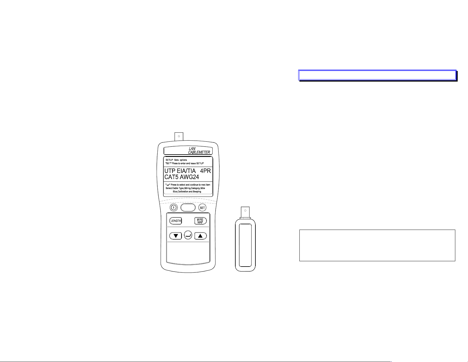
LAN CABLEMETER
46
INSTRUCTION MANUAL
TEST
1
I. INTRODUCTION
The LAN Cable Tester is an easy and effective cable tester with the
ability to identify cable failures, check wiring, and measure cable length
in the UTP (Unshielded twisted pair cable), FTP (Foil – screened
(shielded twisted pair cable), and COAX (Coaxial cable) cables.
It not only identifies wiring faults, such as open wires, shorted wires,
miswires and split pairs, but also tests up to 8 different cables at one
end. A stored cable library provides quick access to common cable
types.
U.S. Pat. No. Des. 446,135
The Cable Tester comes with :
ð One remote identifier #1
RID46-234 (Optional for #2, #3 & #4)
RID46-5678 (Optional for #5, #6, #7 & #8 )
ð One patch cable RJ-45 to RJ-45 30 cm long.
ð RJ45-RJ45 female coupler/connector.
ð Instruction manual.
ð Carrying case & 6 pcs “AAA” 1.5V Battery.
CAUTION
The tester only connects to inactive cables. The input is protected to
withstand low voltages, prolonged connection to active telephone lines
and networks may damage the tester.
TES ELECTRICAL ELECTRONIC CORP.
1
Page 2
II. PRODUCT PROFILE
9
1
COAX FTP/UTP
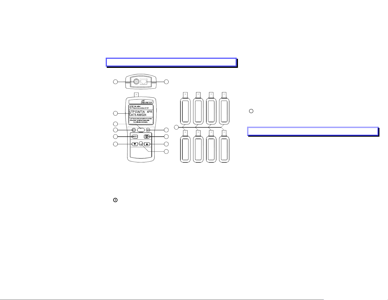
WIREMAP test key : Displays wiring connections, opens, shorts,
and split pairs.
▼ ▲keys : Scroll through a selection of choices or multiple
displays.
10
¿ ENTER key : Enter a selection into the test tool and moves to the
next setting selection.
BNC connector for connecting coaxial cables.
RJ45 jack : Standard 8-pin modular jack for connecting UTP and
FTP cable.
11
1
234
Remote Identifiers #1 ~ #8.
2
3
5
7
LCD Display :
TEST
11
4
6
7
5
8
678
A 2-line by 16-character display. For more information, press ▼ ▲
key to display the additional information.
TEST key : Test the attached cable and indicate a pass or failure
information base on the specified parameters for the selected cable.
Power key : On or Off.
SET key : Access to cable selection, cable calibration, and other test
tool settings.
LENGTH measurement key : Measure the length of each pair of
twisted pair cable or coaxial cables in meters or feet and tests for
anomalies.
2
III. SPECIFICATIONS
Cable Length Measurements
Range : 1.0 to 350m (2-999 ft)
Accuracy : 5% + 1m (5% +3ft)
Resolution : Measurement Units in Feet :
Cables < 100 ft : 0.5 ft
Cables > 100 ft :1ft
Measurement Units in Meters.
Cables < 100 meters : 0.5m
Cables > 100 meters :1m
Failures Detected
SHORTS
Range of short detection : 0 to 350m ( 0 to 999ft)
Accuracy of distance to a short (Assumes short is 0Ω)
UTP/FTP : 7% + 3m (7% + 10ft)
Coaxial Cables : 10% + 10m (10% + 30ft)
3
Page 3
OPENS
Range of open detection : 0 to 350m (0 to 999ft)
Accuracy of distance to an open :
UTP/FTP : 10% + 1m (10% + 3 ft)
SPLIT PAIRS
Range of detection : 2 to 350m (6 to 999ft)
Split pair part of the cable must be at least 2 meters (6ft) in length and
greater than 10% of the total cable length.
COAX Termination Measurements
Any loop resistance value between 5 and 350Ω is interpreted as a
termination resistance. Resistance value below 5Ω is considered
shorts and resistance value greater than 350Ω is not displayed.
General Specifications
Display : 2 lines of 16 characters LCD.
Power : Six AAA size 1.5V batteries.
Low Battery Indication : Display shown “LOW BATTERY”.
Battery Life : 100 hours.
Auto Power off : 5 minutes, (When there is no key activity).
Remote Cable Identifiers : #1 (#2 to #4 and #5 to #8 are optional).
Input Protection : 50V DC.
LAN Input Connectors : RJ45 and BNC.
Environinental Conditions :
Operating : 0 to +40℃ < 80%RH / Storage : -20 to +60℃ < 70%RH
Dimensions : Cable Tester 150 x 72 x 35mm
Remote identifier 60 x 23 x 22mm
Weight : Cable Tester 215g / Remote identifier 35g
IV. SETUP SELECTIONS
The setup mode allows to select and calibrate cable characteristics.
Once changed, these settings are stored and remain in the tester even
when tester is turned off.
Setup items :
r Select cable type (UTP, FTP, or COAX).
r Select a wiring standard.
r Select a cable category.
r Select a wire size.
r Calibrate cable length.
r Enable or disable the Beeper for ON and OFF.
Setup Procedure
1. Press SET key.
2. Press ¿ enter key to set up through the selections.
3. Press ▼ ▲ keys to select the desired setup condition.
4. Press ¿ enter key to move to the next setup selection, or press
SET key to exit the setup mode.
Power–up selection : Select length measurement units between feet
( ft ) and meters (m).
Power–up setup procedure
1. Turn off the tester, press and hold down SET key, then press and
hold down
2. Press ▼or ▲ keys to the desired length units.
3. Press SET key to store the units and exit this mode.
power key, until display show LENGTH UNIT.
4
5
Page 4
Selecting a Cable Type Procedure
1. Press SET key to enter setup mode.
2. Press ▼▲key until the desired “cable” type is displayed, then
press ¿ enter key.
3. Press ▼ ▲key until the desired “wiring” standard is displayed,
then press ¿ enter key.
4. Press ▼ ▲keys until the desired “category” is displayed, then
press ¿ enter key.
5. Press ▼▲key until the desired “wire size” is displayed, then press
¿ enter key.
6. Press ▼▲key until the desired “Beeper” enable or disable,then
press ¿ enter key.
7. Press SET key to exit this mode.
V. CALIBRATING CABLE LENGTH
The cable characteristics parameter is now defined by the factory
settings for the cable selected. But cables are coming from different
batches or manufacturers the characteristic variances will be at up to
20%, to cause deviations in length measurement. To obtain more
accurate measurements, calibrate the tester to the specific cable under
test. For proper calibration connect the cable under test directly to the
tester not through a patch cable. To calibrate the tester to the currently
selected cable, perform the following procedure.
1. Select cable type under test.
2. Connect a good cable of known length, 100 meters, to the
appropriate tester connector.
3. Press SET key, then press ¿ enter key, until the display shown “
CAL TO CABLE ? ”.
4. Press ▼ ▲ key until “YES” is displayed, then press ¿ enter key.
5. Press SET key, “User Cal 100m” is displayed.
6. Press ¿ Key. These cable parameters are stored and will remain in
memory even if the test tool is turned off. All future measurements for
this cable type are compared to these new paraneters, until another
cable is selected or another calibration is performed.
7. Calibrating Cable length for UTP/FTP. Calibration is 100m for
COAX is 10m.
VI. OPERATING
A). Test Cables
The TEST function tests the attached cable based on the cable’s
compliance with the parameters stored in the tester for the selected
cable. To test a cable, perform the following procedures.
1. Select cable type under test.
2. Connect the cable under test to the appropria connector on the
tester.
3. Press TEST key.
The tests are performed depend on whether a remote identifier unit (ID)
is connected to the end of the cable or not.
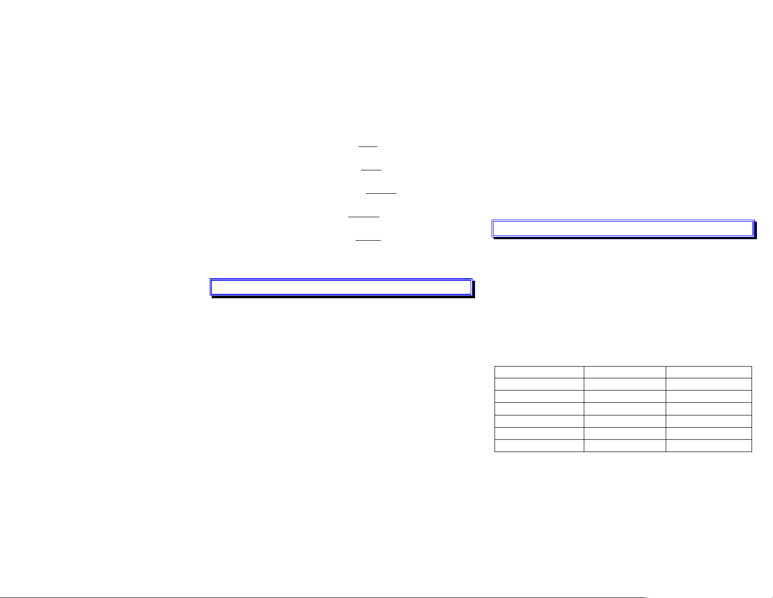
FAILURES DETECTED NO remote unit with remote unit
Short
Open (nearend)
Open (farend)
Length
Split pair
Mis wire
Ö Ö
Ö Ö
Ö
Ö Ö
Ö Ö
Ö
6
7
Page 5
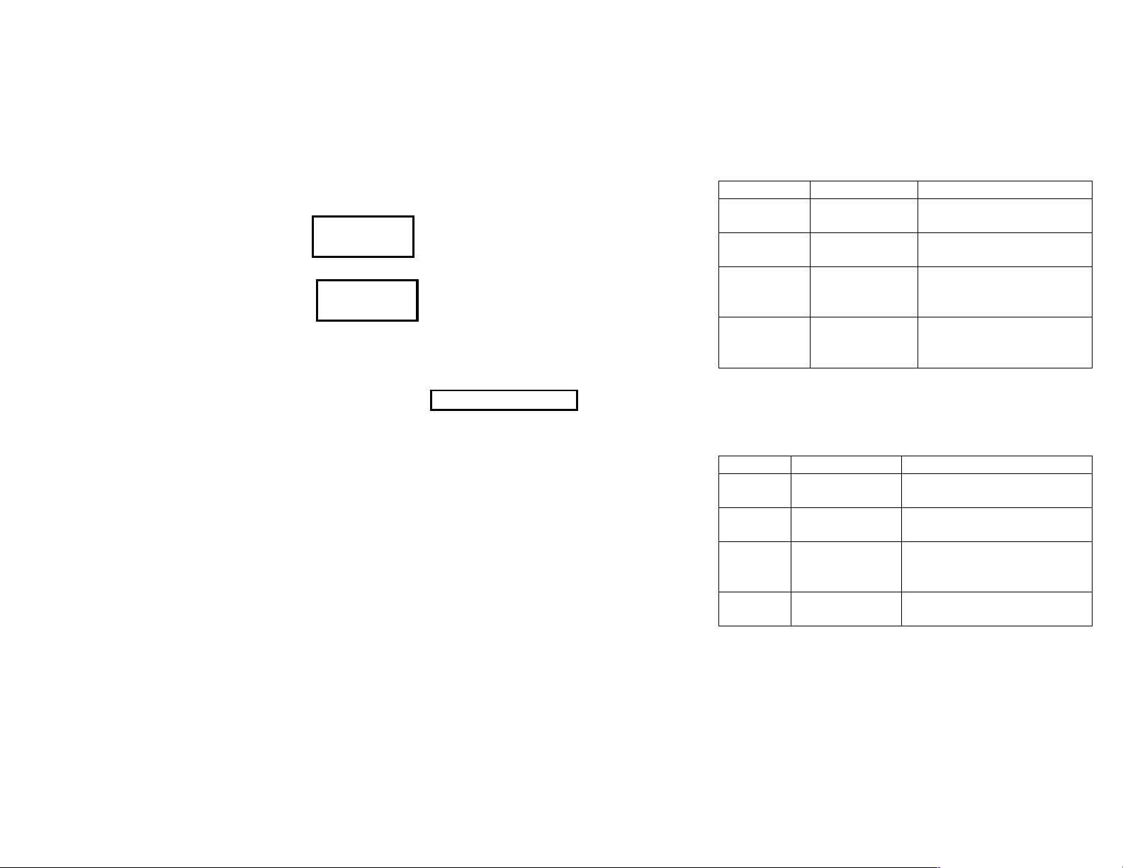
For twisted pair cables, when the tester checks for a cable remote
identifier unit (ID) at the other end of the cable and a pass condition
exists, the LCD will display the following information.
PASS ID#8
100m
PASS ID#?
100m
Good cable, cable remote unit ID#8 detected.
Good cable, no cable remote unit detected or
the tester may not sense the remote unit.
If testing coaxial cable with a termination, the tester dispalys the total
resistance of the cable wires and the terminetion.
COAX ST = 49.0 Ω
Only coaxial cables must be unterminated for the tester to display the
cable’s length. If a coaxial cable is open looks just like an unterminated
cable, then a length measurement that is less than the known cable
length would indicate a possible open in the cable.
The tester if a failure is detected, additional information can be viewed
with the ▼/ ▲keys. The failure messages refer to individval wires
rather than pairs of wires. The TEST mode failure messages are
described in following tables.
Test failures (without remote unit)
FAILURE DISPLAY DESCRIPTION
Short (UTP/FTP) 12 SHORT < 2.1m
Short COAX COAX ST < 10.6m
Displays shorted wires and
most likely distance to the short.
Displays the most likely
distance to the short.
Display open wires and the
OPEN 12 OPEN < 50.5m
open whether it is at the near or
far end of the cable.
Displays wire pairings that are
Split Pair 13 SPLIT PR
incorrect based on the cable
selected.
A short greater than 0Ω, will cause display a length greater than the
actual distance to the short. The tester uses 0Ω to calculate distance
to a short.
Test Failures with remote unit
FAILURE DISPLAY DESCRIPTION
Miswire 12 63 45 78
Open 6 OPEN < 100.0m
Display the incorrect wiring of the
end connectors.
Display the broken wire and the
distance to the break.
Indicates that the length of the pairs
Pair Length PAIR LENGTH
within a cable are abnormal
different.
Split Pair 13 SPLIT PR
A portion of the cable assembly has
split pairs or a poor quality cable.
8
9
Page 6
B). Cable Length Measurment
33662
2
The tester measures the length of both twisted-pair and coaxial
cables. If the tester is not calibrated to the cable under test, then
factory default cable characteristisc are used to compute the length.
If a more accurate length measurement is desired, refer to
“CALIBRATING CABLE LENGTH” described on this manual.
Before a length measurement is made, the tester perfom “Test
Cables” described on this manual to prevent any cable failures from
corrupting the length measurement.
Cable length measure procedure.
1. Select cable type under test.
2. Connect the cable and test to the appropriate connector on the
tester.
3. Press LENGTH key.
4. Use ▼or ▲key to scroll selection multiple displays.
The information that is displayed depends on the type of cable
selected. For twisted pair cable, each pair has corresponding length
measurement.
A 5% difference in length botween pairs, is uncommon.
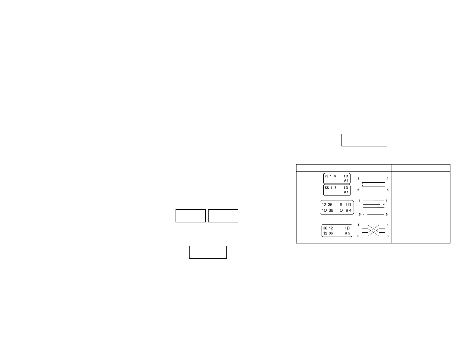
12 100m 45 99.5m
For 100m UTP
36 100m 78 100m
The length of coaxial cable terminated in a resistance cannot be
determined by the tester.
C). WIRE MAP CHECKING
Use the tester wiremap function and remote identifier unit (ID), to
determine the wiring status of both the near end and far end of the
cable.
Wire Map measure procedure.
1. Select cable type under test.
2. Connect the cable under test to the appropriate connector on the
tester.
3. Press WIRE MAP key.
Near End → Good cable with
Far End → remote unit
12 36 45 78 ID
12 36 45 78 #8
Wire Map Failure Using remote unit (ID).
FAILURE DISPLAY WIRING DESCRIPTION
Alternately display an “s”
Short
(near end)
Open
Miswire
2
3
2 2
with actual wire number of
2
3
each wire shorted.
Alternately display “o” with
the number of each open
wire.
Displays the wiring detected
by the test tool and flash the
33
wire numbers involved in the
anomaly.
For 100m coaxial cable
COAX 100m
10
11
Page 7
VII. MAINTENANCE
1. Cleaning :
Periodically wipe the case with a damp cloth and mild detergent.
Do not use abrasives or solvents. Clean and dry as required.
2. Battery replacement :
When LCD display shows “LOW BATTERY”, the power of battery
has already been in-sufficient to support an accurate test. At this
moment replace it with new battery from the battery compartment.
12
Dec-2001-1
 Loading...