


BCT Trima

®
Trima Accel
Automated Blood
Collection System
Service Manual

®
Trima Accel
Automated Blood Collection System
Service Manual
Part No. 777095-548
2015-09

©2015 Terumo BCT, Inc.
Terumo BCT is a registered trademark of Terumo Corporation.
VxWorks is a registered trademark of Wind River Systems, Inc.
Terumo BCT, Inc.
10811 W. Collins Avenue
Lakewood, Colorado 80215
USA
USA Phone: +1.877.339.4228
Phone: +1.303.231.4357
USA Fax: +1.866.715.6768
Fax: +1.303.542.5215
Terumo BCT Europe N.V.
Ikaroslaan 41
1930 Zaventem
Belgium
Phone: +32.2.715.05.90
Fax: +32.2.721.07.70
TERUMOBCT.COM

Contents
Preface
1: Operational Description
System Directory ................................................................................................................................................ 1-2
Boot Sequence .................................................................................................................................................. 1-11
Blood Collection Process .................................................................................................................................. 1-12
Pump System ................................................................................................................................................... 1-14
Sensor System ................................................................................................................................................... 1-19
Pressure Sensors ....................................................................................................................................... 1-20
AC Sensor ................................................................................................................................................ 1-21
Reservoir Level Sensors ............................................................................................................................ 1-22
RBC Detector .......................................................................................................................................... 1-23
Leak Detector .......................................................................................................................................... 1-25
Centrifuge System ............................................................................................................................................ 1-27
Filler Assembly ......................................................................................................................................... 1-31
Door System .................................................................................................................................................... 1-32
Valve System .................................................................................................................................................... 1-36
Linear Actuator ................................................................................................................................................ 1-41
E-Box ............................................................................................................................................................... 1-43
Display System ................................................................................................................................................. 1-47
Power System ................................................................................................................................................... 1-51
Mechanical Systems .......................................................................................................................................... 1-52
2: System Description
Pump System ..................................................................................................................................................... 2-2
Pump Assembly ......................................................................................................................................... 2-5
Sensor System ..................................................................................................................................................... 2-7
Pressure Sensors ......................................................................................................................................... 2-8
Reservoir Level Sensors ............................................................................................................................ 2-10
Trima Accel
®
Automated Blood Collection System • Service Manual i

AC Sensor ................................................................................................................................................ 2-13
RBC Detector .......................................................................................................................................... 2-14
Leak Detector .......................................................................................................................................... 2-15
Centrifuge System ............................................................................................................................................ 2-18
Centrifuge Drive Assembly ...................................................................................................................... 2-22
Centrifuge Motor Controller ................................................................................................................... 2-23
Door System .................................................................................................................................................... 2-26
Valve System .................................................................................................................................................... 2-31
Linear Actuator System .................................................................................................................................... 2-37
E-Box and Computer Systems .......................................................................................................................... 2-40
Control and Safety Functions .................................................................................................................. 2-42
Control CCA ........................................................................................................................................... 2-43
Control Computer ................................................................................................................................... 2-46
Control Ethernet CCA ............................................................................................................................ 2-47
Safety CCA .............................................................................................................................................. 2-48
Safety Computer ...................................................................................................................................... 2-50
Safety Ethernet CCA ............................................................................................................................... 2-51
Motor Driver CCA .................................................................................................................................. 2-52
64 V Switch CCA .................................................................................................................................... 2-54
Cooling Fans .................................................................................................................................................... 2-56
Display System ................................................................................................................................................. 2-58
Display Assembly ..................................................................................................................................... 2-61
Display CCA ........................................................................................................................................... 2-64
Power System ................................................................................................................................................... 2-66
Mechanical System ........................................................................................................................................... 2-70
IV Pole .................................................................................................................................................... 2-70
Wheel and Brake System ......................................................................................................................... 2-71
3: Software Description
Version 5.1 Software Description ....................................................................................................................... 3-2
Trima Accel Software Description ............................................................................................................. 3-2
State and Substate Overview ...................................................................................................................... 3-2
Self Test State ............................................................................................................................................ 3-7
Power Fail Recovery State .......................................................................................................................... 3-9
Startup Tests State ..................................................................................................................................... 3-9
Disposable Tests State .............................................................................................................................. 3-14
AC Connected State ................................................................................................................................ 3-18
AC Prime State ........................................................................................................................................ 3-18
Donor Connected State ........................................................................................................................... 3-19
Blood Prime State .................................................................................................................................... 3-20
Blood Run State ...................................................................................................................................... 3-22
ii
Trima Accel® Automated Blood Collection System • Service Manual

Rinseback State ........................................................................................................................................ 3-33
Donor Disconnect State .......................................................................................................................... 3-35
Post Run State ......................................................................................................................................... 3-37
Version 6.0 Software Description ..................................................................................................................... 3-38
Trima Accel Software Description ........................................................................................................... 3-38
Self Test State .......................................................................................................................................... 3-38
Power Fail Recovery State ........................................................................................................................ 3-40
Startup Tests State ................................................................................................................................... 3-40
Disposable Tests State .............................................................................................................................. 3-45
AC Connected State ................................................................................................................................ 3-52
AC Prime State ........................................................................................................................................ 3-53
Donor Connected State ........................................................................................................................... 3-54
Blood Prime State .................................................................................................................................... 3-55
Blood Run State ...................................................................................................................................... 3-57
Rinseback State ........................................................................................................................................ 3-69
Donor Disconnect State .......................................................................................................................... 3-71
Metered Storage Solution State ................................................................................................................ 3-73
Metered Storage Solution Disconnect State ............................................................................................. 3-80
Post Run State ......................................................................................................................................... 3-82
Version 6.1 Software Description ..................................................................................................................... 3-83
Trima Accel Software Description ........................................................................................................... 3-83
Self Test State .......................................................................................................................................... 3-83
Power Fail Recovery State ........................................................................................................................ 3-85
Startup Tests State ................................................................................................................................... 3-85
Disposable Tests State .............................................................................................................................. 3-90
AC Connected State ................................................................................................................................ 3-98
AC Prime State ........................................................................................................................................ 3-98
Donor Connected State ........................................................................................................................... 3-99
Blood Prime State .................................................................................................................................. 3-100
Blood Run State .................................................................................................................................... 3-102
Blood Rinseback State ........................................................................................................................... 3-114
Donor Disconnect State ........................................................................................................................ 3-116
Metered Storage Solution State .............................................................................................................. 3-118
Metered Storage Solution Disconnect State ........................................................................................... 3-126
Post Run State ....................................................................................................................................... 3-127
Trima Accel
®
Automated Blood Collection System • Service Manual iii

4: Troubleshooting
Touch Screen Troubleshooting .......................................................................................................................... 4-2
Valve System Troubleshooting ........................................................................................................................... 4-4
Version 6.0.6 Dlog Information .............................................................................................................. 4-10
Door System Troubleshooting .......................................................................................................................... 4-17
Version 6.0.6 Dlog Information .............................................................................................................. 4-24
5: Maintenance and Calibration
Aligning the Centrifuge Door ............................................................................................................................. 5-2
Calibrating the Centrifuge Motor Controller ..................................................................................................... 5-5
Positioning the Linear Actuator Sensors ............................................................................................................. 5-8
Removing the Side Panels ................................................................................................................................. 5-11
Saline Run ........................................................................................................................................................ 5-14
6: Specifications
Physical Specifications ........................................................................................................................................ 6-2
Environmental Specifications ............................................................................................................................. 6-3
Electrical Power and Safety ................................................................................................................................. 6-4
Safety Certifications .......................................................................................................................................... 6-11
Performance Specifications ............................................................................................................................... 6-12
Product Specifications ...................................................................................................................................... 6-13
Blood Tubing Sets ............................................................................................................................................ 6-14
Centrifuge ........................................................................................................................................................ 6-15
Safety ............................................................................................................................................................... 6-16
Draw/Return Pressure Sensor ........................................................................................................................... 6-17
Centrifuge Pressure Sensor ............................................................................................................................... 6-18
Reservoir Level Sensors ..................................................................................................................................... 6-19
Fluid Leak Detector .......................................................................................................................................... 6-20
Anticoagulant (AC) Detector ............................................................................................................................ 6-21
RBC Spillover Detector .................................................................................................................................... 6-22
Anticoagulant (AC) Flow Alarm ....................................................................................................................... 6-22
Anticoagulant (AC) Ratio Alarm ...................................................................................................................... 6-23
Anticoagulant (AC) Infusion Alarm .................................................................................................................. 6-24
Touch-Screen Display ...................................................................................................................................... 6-25
Symbols and Certification ................................................................................................................................ 6-26
Seal Safe System Specifications ......................................................................................................................... 6-29
Index
iv
Trima Accel® Automated Blood Collection System • Service Manual

Preface
The Trima Accel Automated Blood Collection System Service Manual provides the information needed
to service and troubleshoot the system. This manual applies to versions 5.1.0 and higher. For version 5.0
systems, see the Trima Accel Automated Blood Collection System Service Manual PN 777821-113, RN
704111-003.
Who Should Read This Manual
This manual is intended for Terumo BCT service technicians and employees, trained and qualified
customer technical staff, and Terumo BCT service partners. Only these trained personnel are permitted
to service the device and replace parts.
Trima Accel
®
Automated Blood Collection System • Service Manual v

Preface
How to Use This Manual
This manual is divided into sections that can be read and used separately.
Title Description
Operational
Description
System Description Describes the functional and electronic principles of certain device systems and components.
Software Description Describes the software that the device uses to operate.
Alarms Provides alarm text and alarm information.
Troubleshooting Describes non-alarm troubleshooting.
Maintenance and
Calibration
Describes the function and location of certain device systems and components.
Describes maintenance and service procedures for the device.
vi Trima Accel® Automated Blood Collection System • Service Manual

1
Operational Description
Trima Accel® Automated Blood Collection System • Service Manual 1-1

Operational Description
System Directory
The Trima Accel system consists of several major subsystems, such as the display, the pump panel, the
centrifuge chamber, and the electronics box (e-box).
The system directory shows the names and locations of some major systems and components in relation
to the whole device. There are figures showing front views and rear views with callout lists to identify
components in each figure. Some figures may not show a callout in the front view, but it will be present
in the rear view. Components that are not called out in the system directory are explained in detail in
their respective Operational Description sections.
1-2 Trima Accel® Automated Blood Collection System • Service Manual
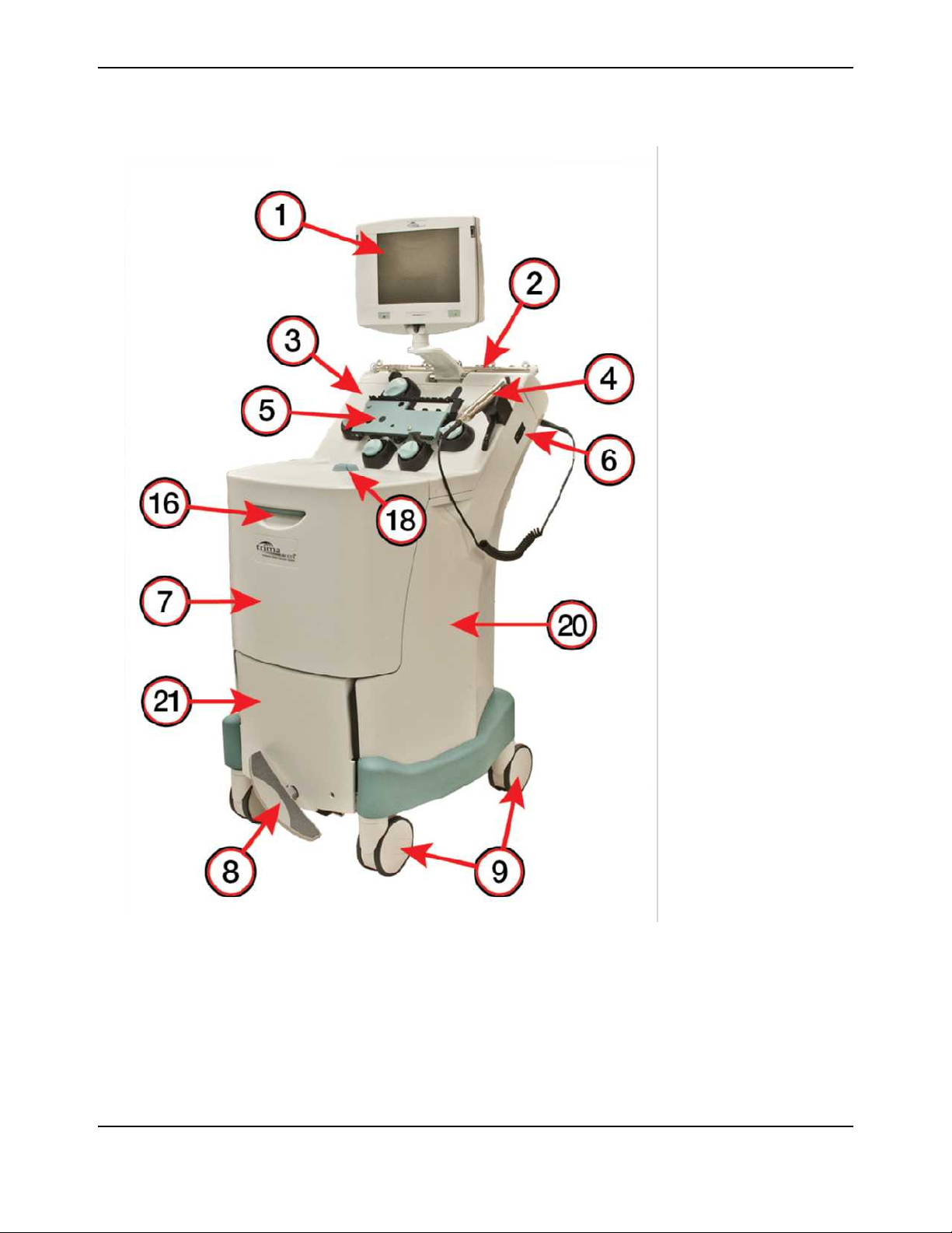
Trima Accel Device Exterior
System Directory
1
Display
2
IV pole
3
Pump panel
4
Seal Safe system
5
Cassette plate
6
Power switch
7
Centrifuge door
8
Brake pedal
9
Swivel caster
10
Handle wheels
11
System serial number
12
IV pole button
13
Power cord
14
Power cord holder
15
Ethernet connection
16
Door latch handle
17
Circuit breaker
18
Loop damper
19
Handheld barcode
reader outlet
20
Side panel
21
Front panel
22
Rear panel
23
Linear actuator screw
access hole
Figure 1-1: The Trima Accel system, front view
Trima Accel® Automated Blood Collection System • Service Manual 1-3
Operational Description
1
Display
2
IV pole
3
Pump panel
4
Seal Safe system
5
Cassette plate
6
Power switch
7
Centrifuge door
8
Brake pedal
9
Swivel caster
10
Handle wheels
11
System serial number
12
IV pole button
13
Power cord
14
Power cord holder
15
Ethernet connection
16
Door latch handle
17
Circuit breaker
18
Loop damper
19
Handheld barcode
reader outlet
20
Side panel
21
Front panel
22
Rear panel
23
Linear actuator screw
access hole
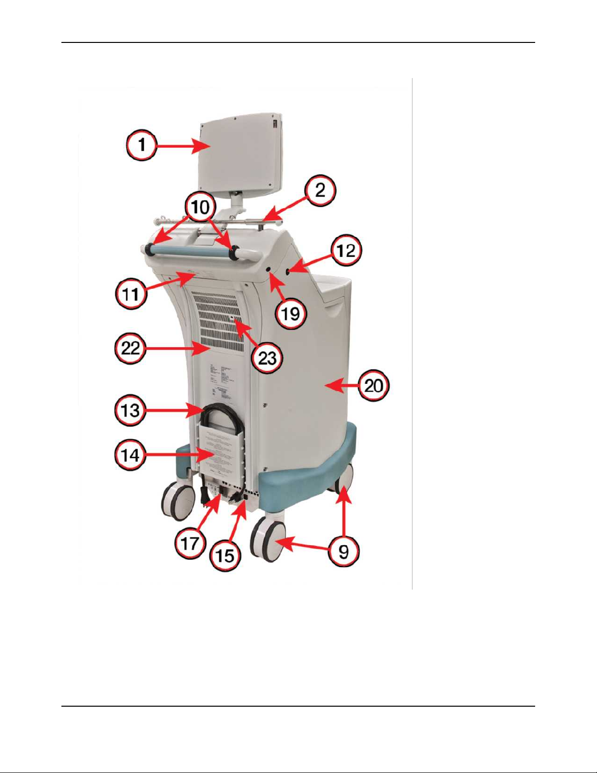
Figure 1-2: The Trima Accel system, rear view
1-4 Trima Accel® Automated Blood Collection System • Service Manual

System Directory
Table 1-1: Trima Accel system components
Component Function
1 Display Allows you to communicate with the system through audio, visual, or touch-
screen interfaces.
2 IV pole Contains hooks for hanging bags and containers. Adjusts up and down for
transport.
3 Pump panel Holds the pumps, valves, sensors and detectors.
4 Seal Safe system Seals the lines of the tubing set.
5 Cassette plate Holds the tubing set cassette in place.
6 Power switch Allows you to turn power to the system on and off.
7 Centrifuge door Allows access to the centrifuge chamber.
8 Brake pedal Allows you to adjust the direction of the swivel casters for moving the system or to
lock the swivel casters in place so that the system does not roll.
9 Swivel casters (4) Used to transport the system.
10 Handle wheels (2) Facilitates transport of the system in a horizontal position.
11 System serial number Unique number that identifies the system.
12 IV pole button Allows you to lower the IV pole by pressing the button.
13 Power cord Connects the system to a power source.
14 Power cord holder Secures the power cord during transport.
15 Ethernet connection Allows the service computer to communicate with the device.
16 Door latch handle Allows you to open the centrifuge door.
17 Circuit breaker Protects the system from an electrical surge. Secondary power switch used to
power the system on and off.
18 Loop damper Reduces the vibration of the disposable tubing set during a procedure.
19 Handheld barcode reader
outlet
Connects the optional barcode reader assembly.
20 Side panel Covers and protects the internal components from damage, provides containment
in case of catastrophic failure, and is a cosmetic feature.
21 Front panel Covers and protects the internal components from damage, provides containment
in case of catastrophic failure, and is a cosmetic feature.
Trima Accel® Automated Blood Collection System • Service Manual 1-5

Operational Description
Table 1-1: Trima Accel system components (continued)
Component Function
22 Rear panel Covers and protects the internal components from damage, holds the power cord,
vents heat from inside the device, and allows access to the screw that is used to
manually raise the cassette plate (used during power failure).
23 Linear actuator screw
access hole
Allows tool access to manually raise the cassette plate to allow the operator to
unload a disposable tubing set if power is lost during a procedure.
1-6 Trima Accel® Automated Blood Collection System • Service Manual
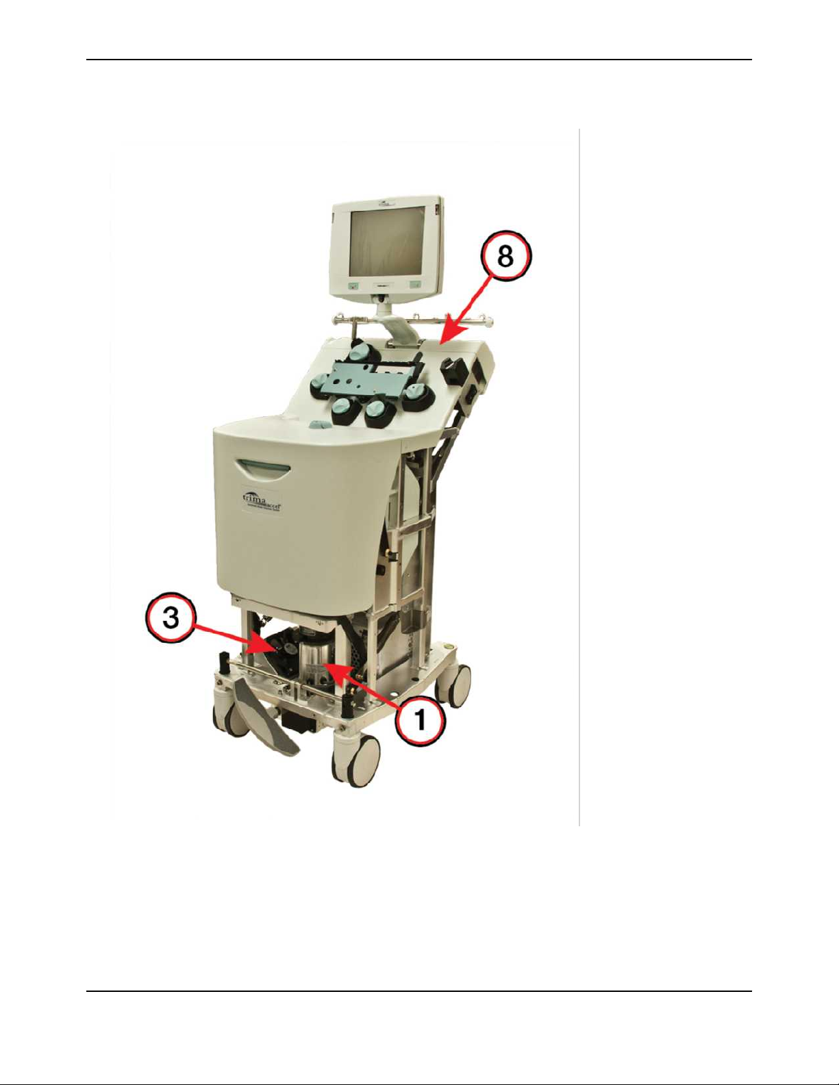
Trima Accel Device Interior
System Directory
1
Centrifuge motor
2
E-box
3
Lower compartment
cooling fan 1
4
Upper compartment
cooling fan 2
5
E-box cooling fan 3
(inside e-box)
6
Linear actuator screw
7
Leak detector CCA
8
Top cap assembly
9
ESD service strap
Figure 1-3: The Trima Accel system with no panels, front view
Trima Accel® Automated Blood Collection System • Service Manual 1-7
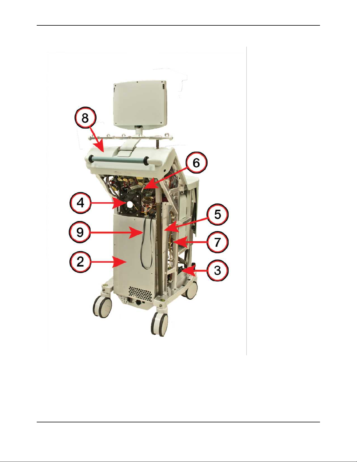
Operational Description
1
Centrifuge motor
2
E-box
3
Lower compartment
cooling fan 1
4
Upper compartment
cooling fan 2
5
E-box cooling fan 3
(inside e-box)
6
Linear actuator screw
7
Leak detector CCA
8
Top cap assembly
9
ESD service strap
Figure 1-4: The Trima Accel system with no panels, rear view
1-8 Trima Accel® Automated Blood Collection System • Service Manual

System Directory
Table 1-2: Trima Accel system components
Component Function
1 Centrifuge motor Spins the disposable tubing set channel that is used to separate blood into its
components.
2 E-box Contains CCAs for the safety and control systems, the hard drive, the motor drive
systems, and the power supply.
3 Lower compartment
cooling (fan 1)
4 Upper compartment
cooling (fan 2)
5 E-box cooling (fan 3) Provides airflow that is used to cool the e-box electronics.
6 Linear actuator screw Raises or lowers the cassette plate when the motor is activated.
7 Leak detector CCA Contains the leak detector circuitry.
8 Top cap assembly Contains the display arm assembly, the handle, the Seal Safe connector, and the
9 ESD service strap Provides a secondary ESD (electrostatic discharge) strap if the service
Provides airflow that is used to cool the centrifuge motor and basin.
Provides airflow that is used to cool the pump and valve motors.
barcode reader connector and interfaces with the IV pole. This is a replaceable
component.
technician does not have a primary ESD strap.
Trima Accel® Automated Blood Collection System • Service Manual 1-9
Operational Description
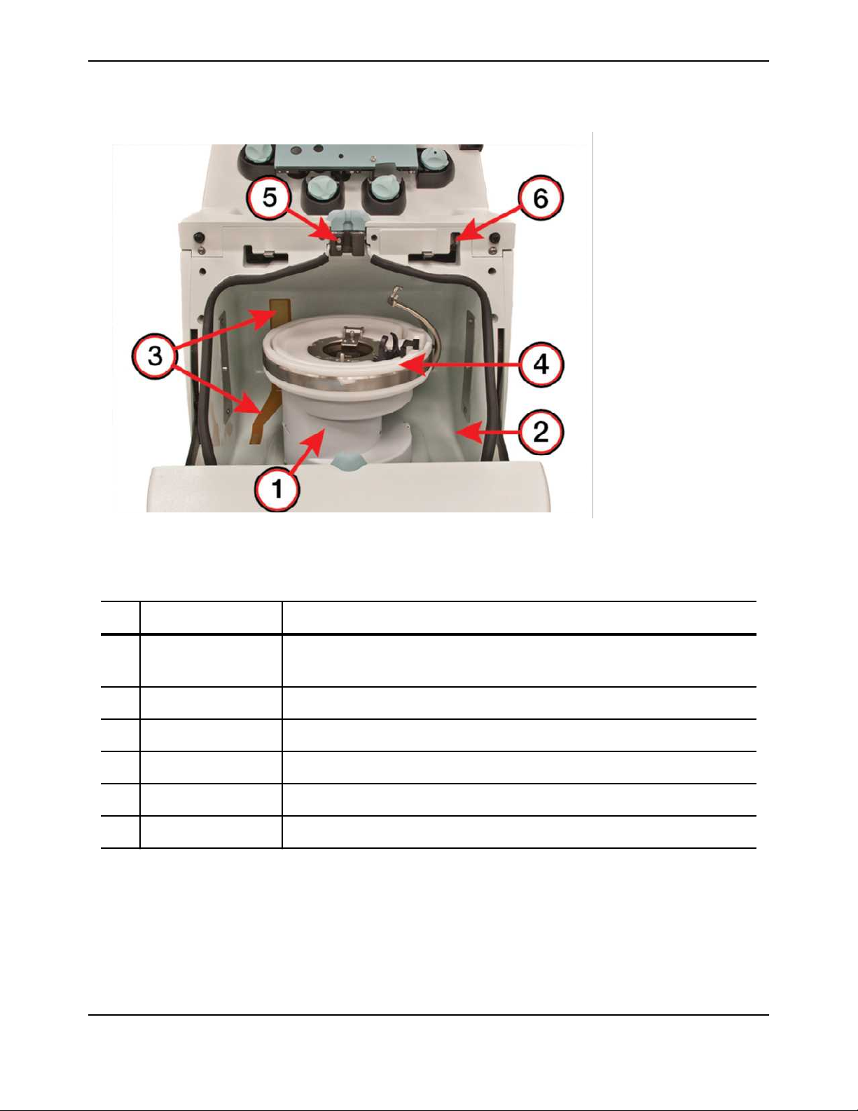
Trima Accel Centrifuge Basin
1
Centrifuge
2
Basin
3
Leak detector
4
Filler assembly
5
Upper hex holder
6
Door lock with sensors
Figure 1-5: The Trima Accel basin
Table 1-3: Trima Accel basin components
Component Function
1 Centrifuge Spins the disposable tubing set channel that is used to separate blood into its
components.
2 Basin Provides protection from catastrophic centrifuge failure and contains fluid leaks.
3 Leak detector Senses fluid in the basin from leaks in the channel or tubing.
4 Filler assembly Holds the disposable tubing set channel where blood component separation occurs.
5 Upper hex holder Holds and locks disposable tubing when the centrifuge door is closed.
6 Door lock with sensors Ensures that the centrifuge door cannot be opened while the centrifuge is spinning.
1-10 Trima Accel® Automated Blood Collection System • Service Manual

Boot Sequence
Boot Sequence
This section describes the boot sequence and when to interrupt that sequence for troubleshooting and
maintenance purposes.
When it is turned on, the Trima Accel device performs a low-level memory check, generating an alarm if
this check fails. If this check is successful, the device moves on to the boot sequence.
It is possible to interrupt the boot sequence for three different scenarios.
The first scenario is to enter Single-Step mode, which is used to connect the device to STS with an FTP
connection, usually after the safety computer fails to boot and dlogs need to be recovered. To enter
Single-Step mode, press and hold the pause button after the memory check until the screen shows that
the pause button is detected. Then press the pause button to advance through each step of the boot
sequence. Stop at the message line “press and release pause button to initialize serial port driver.”
In FTP mode, STS does not auto-discover the Trima Accel device. To connect, select device type Trima
from the drop-down menu and enter the serial number, or enter the IP address 172.21.127.255 to
connect to a new hard drive. Accept any FTP warnings that appear.
The second scenario is to enable the software load installation script, which is used after new software has
been loaded and needs to be installed. To run the installation script, press and hold the pause and stop
buttons after the memory check, a few seconds after the power is on, and hold the buttons until the
message line “Installation script found—release buttons to execute.” Wait for another message line
reading “Installation complete—cycle power to restart.” Then boot to the two-button donor screen, and
check to make sure the changes took place.
Note:
The device allows only one chance to interrupt the normal boot sequence to install new files or software. All
calibration and software data is lost if the device boots to the two-button donor screen after uploading files to the
device. If this installation script is not activated on the first boot, then calibration and software transfer must be
performed again.
The third scenario is to enter Service mode, which is used for software installations, updates, device
maintenance, and device troubleshooting. To enter Service mode, press and hold the pause and stop
buttons after the screen shows the volume checks, and do not release the buttons until the screen
prompts you to do so.
After the boot sequence is finished, the device then checks the power supply voltages, performs valve
position tests, checks the leak detector voltage, and tests the door lock functionality. Without errors to
any of these items the software is then loaded into Procedure mode (two-button donor screen).
Trima Accel® Automated Blood Collection System • Service Manual 1-11
Operational Description
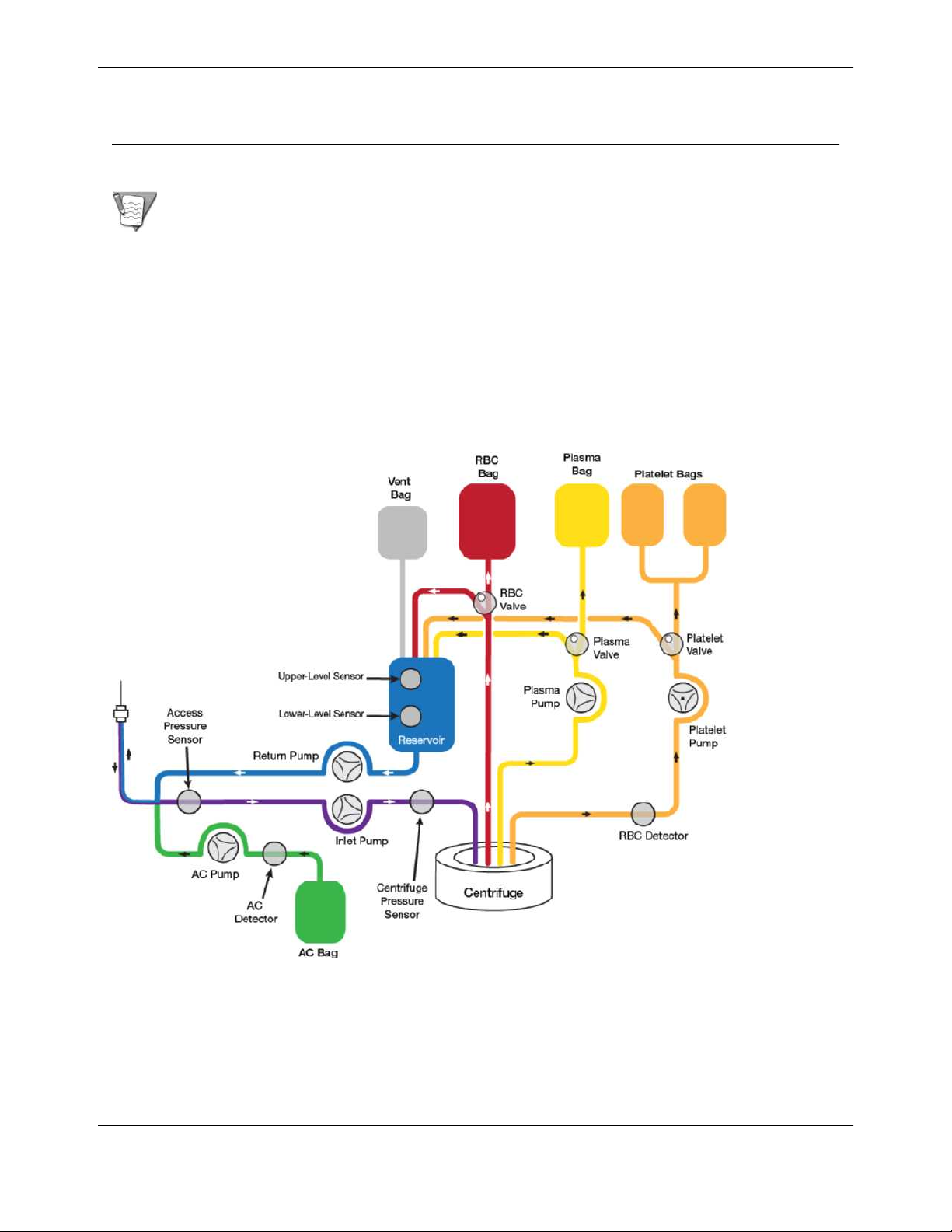
Blood Collection Process
This section describes the blood collection process.
Note: This section describes the blood collection process from the standpoint of the device electronics for field
service personnel. See the Operator’s Manual for detailed procedural information for the operator.
The Trima Accel system operates automatically when it is in Procedure mode. Pumps control the flow of
inlet blood, anticoagulant, platelets, plasma, and return blood. Centrifugal force and the inlet pump
control the red blood cell (RBC) flow. Donor data that is entered at the beginning of the procedure helps
the Trima Accel system perform software calculations (algorithms) that control operations. This donor
data—height, weight, and gender—is used to calculate the total blood volume (TBV) of the individual.
Once the Trima Accel system accumulates this data, it recommends optimal procedures or
combinations of products, and the operator chooses a procedure based on donor time limits. When the
Trima Accel system receives procedure instructions, it can set pump flow rates and centrifuge speed.
Automatic control of the RBC/plasma interface optimizes blood separation.
Figure 1-6: Trima Accel fluid flow diagram
First, the disposable tubing set is loaded onto the Trima Accel system. Once the cassette is loaded, the
Trima Accel system prompts the operator to clamp both the needle line and the sample bag line. The
anticoagulant (AC), return, and inlet pumps are run to pressure test the tubing set. If the tests are not
successfully completed, alarms are generated.
1-12 Trima Accel® Automated Blood Collection System • Service Manual

Blood Collection Process
The Trima Accel system prompts the operator to prime the system by connecting the AC bag. The AC
pump forces anticoagulant through the inlet line to the access and return lines. The operator then
performs the venipuncture and opens the clamp on the needle line. The return pump (rotating in
reverse) pulls blood into the return line until blood reaches the lower-level sensor in the return reservoir.
At this point, the initial priming sequence initiates.
The procedure starts with the inlet pump drawing blood into the Trima Accel system through the
single-needle access. Anticoagulant, pumped by the AC pump at a configured ratio, is infused into the
system close to the needle. The inlet pump continues to pump blood into the centrifuge, which has
started rotation. The centrifuge accelerates at controlled rates, then holds at 2,000 rpm for 2 minutes
before accelerating to its final commanded speed. At this point, the Trima Accel system enters run mode
and the pumps accelerate to their commanded run mode speeds.
The control and safety computers monitor several items during startup of the procedure. The first return
cycle is monitored closely due to the high amount of AC in the Trima Accel system during startup. An
over-delivery of volume during the first return cycle results in a safety shutdown of the Trima Accel
system for this reason. Once the startup phase is complete, return cycle volume problems can cause
alarms, but the procedure can be continued.
The actual separation of blood components occurs inside the channel portion of the tubing set. Whole
blood enters into the channel and is separated into its various components by centrifugal force.
Three valves divert the blood components that are being collected—which may include plasma,
platelets, and/or RBC—into collect bags. If any of these components are not being collected, the valves
route them to the return reservoir located on the front panel of the Trima Accel system. When the
reservoir contains an appropriate volume (approximately 55 mL), the upper-level reservoir sensor
triggers and activates the return pump. The return pump interrupts the incoming flow of blood to the
cassette by pushing return blood back through the single-needle access until the reservoir empties
(reaches the lower-level sensor). The inlet pump remains at a constant speed during this entire cycle.
This causes a small amount of return blood to re-circulate back through the inlet pump and into the
channel, maintaining continuous blood flow to the interface. The AC pump shuts off during the return
cycle. The return pump turns off after the reservoir empties.
Trima Accel® Automated Blood Collection System • Service Manual 1-13
Operational Description
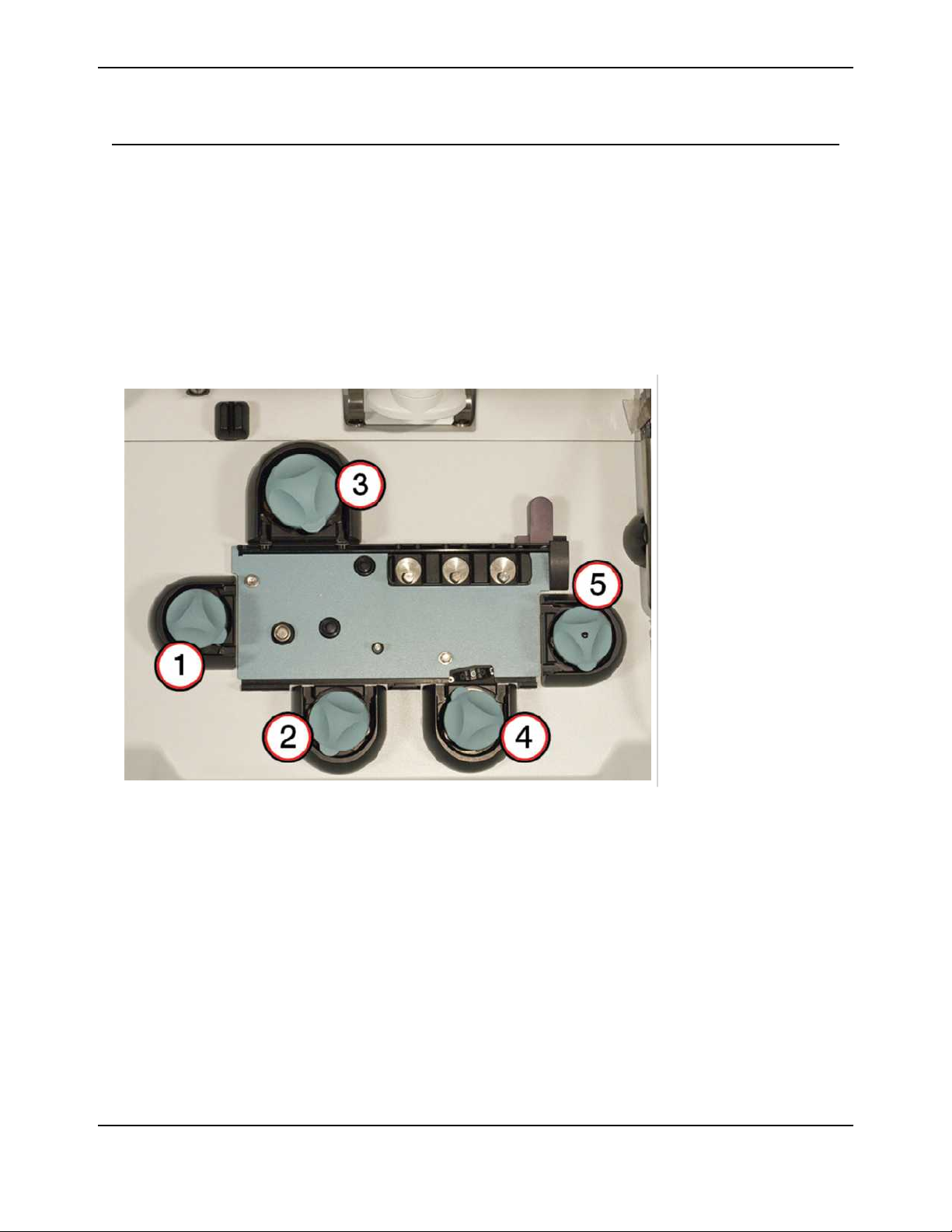
Pump System
The Trima Accel device uses five pumps to move anticoagulant, blood, and blood components through
the disposable tubing set using peristaltic action.
Each pump consists of a pump motor, a pump rotor, a seal, and a raceway housing. The platelet pump
spins at a significantly slower rate than the rest of the pumps, so it needs two magnets in the rotor to
properly measure speed. The platelet pump rotor is marked with a black dot for recognition. The return
pump, which has a larger diameter, is the only pump able to spin in both directions; all other pumps spin
in a counterclockwise direction.
Pump Locations
1
AC pump
2
Inlet pump
3
Return pump
4
Plasma pump
5
Platelet pump
Figure 1-7: Pump locations (front)
1-14 Trima Accel® Automated Blood Collection System • Service Manual
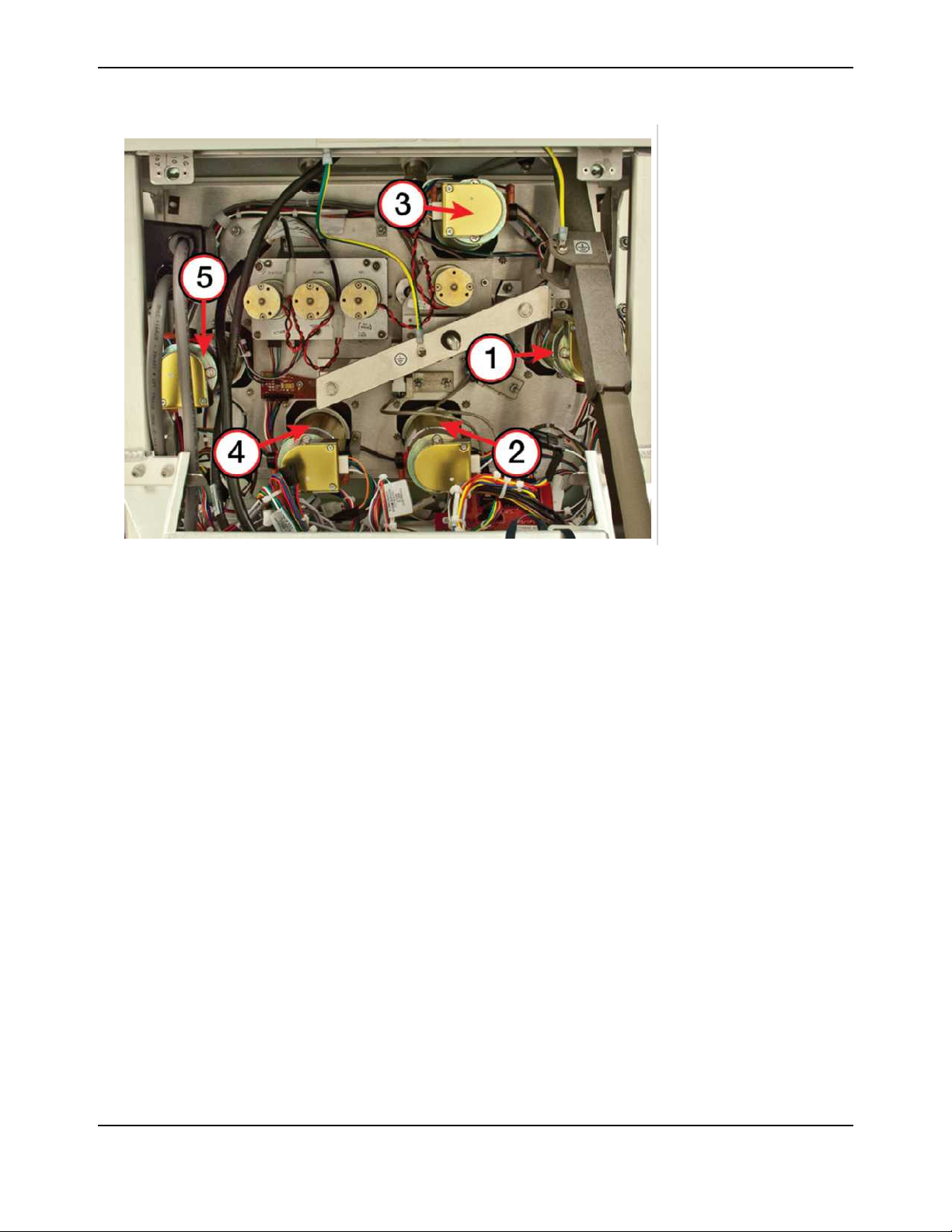
1
AC pump (behind IV
pole)
2
Inlet pump
3
Return pump
4
Plasma pump
5
Platelet pump
Pump System
Figure 1-8: Pump locations (rear)
Trima Accel® Automated Blood Collection System • Service Manual 1-15
Operational Description
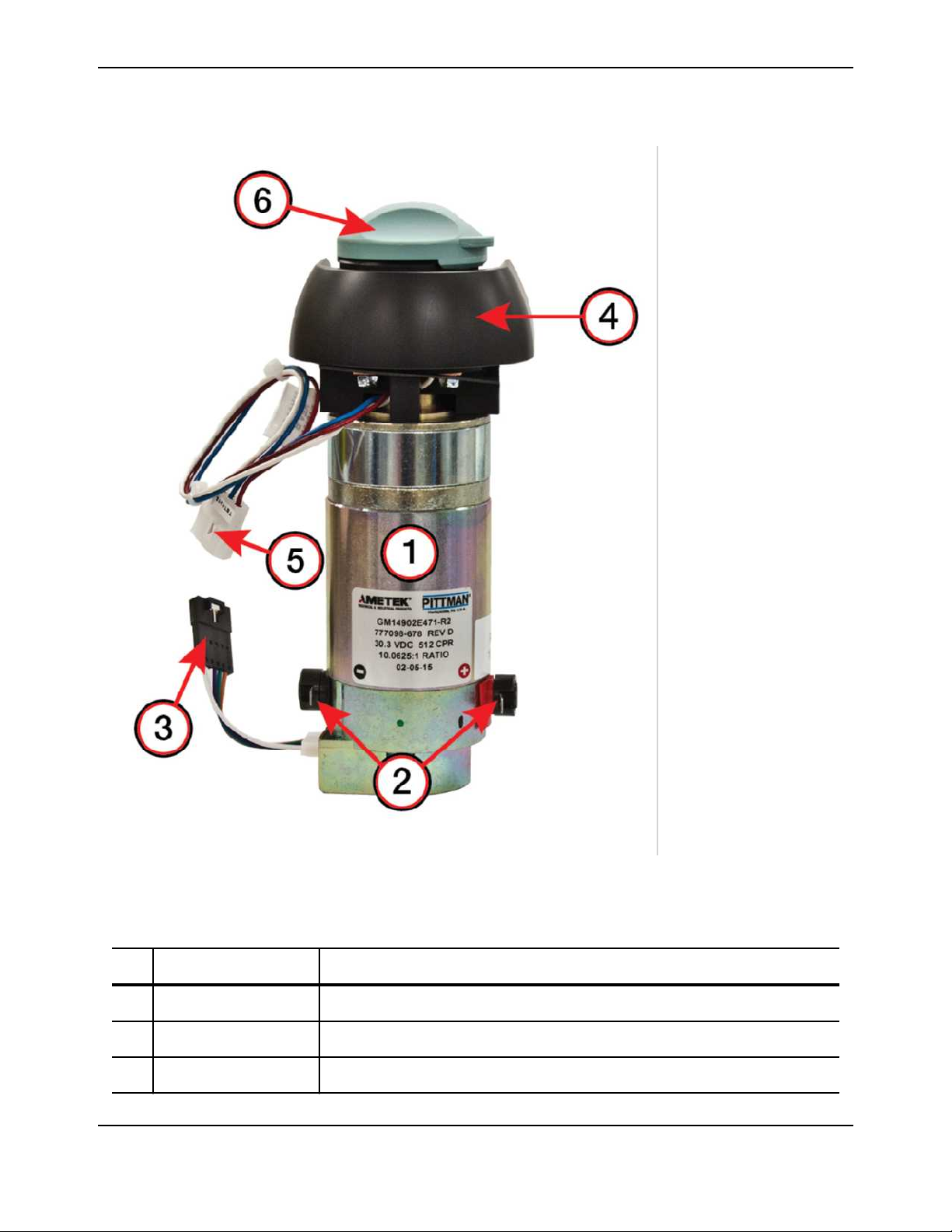
Pump Assembly
1
Pump motor
2
Drive terminals
3
Encoder connector
4
Pump raceway
housing
5
Hall-effect sensor
connector
6
Pump rotor
Figure 1-9: Pump system components
Table 1-4: Pump system components
Component Function
1 Pump motor Turns the rotor to move fluids through the disposable tubing set.
2 Drive terminals Connect the pump to 24 V power.
3 Encoder connector Sends pump speed encoder data from the pump motor to the e-box.
1-16 Trima Accel® Automated Blood Collection System • Service Manual
Pump System
Table 1-4: Pump system components (continued)
Component Function
4 Pump raceway housing Mounts the pump motor and the Hall-effect sensor. It also has a machined raceway
that is designed to accept the disposable tubing set.
Note: The pump motors can be removed without removing or loosening any of the pump
raceways. If a pump raceway is removed or loosened, an alignment tool is necessary to
reinstall it.
5 Hall-effect sensor
connector
6 Pump rotor Attaches to the pump motor shaft and uses two spring-loaded rollers to provide the
Sends pump speed pulses from the raceway to the e-box.
peristaltic action in the disposable tubing set.
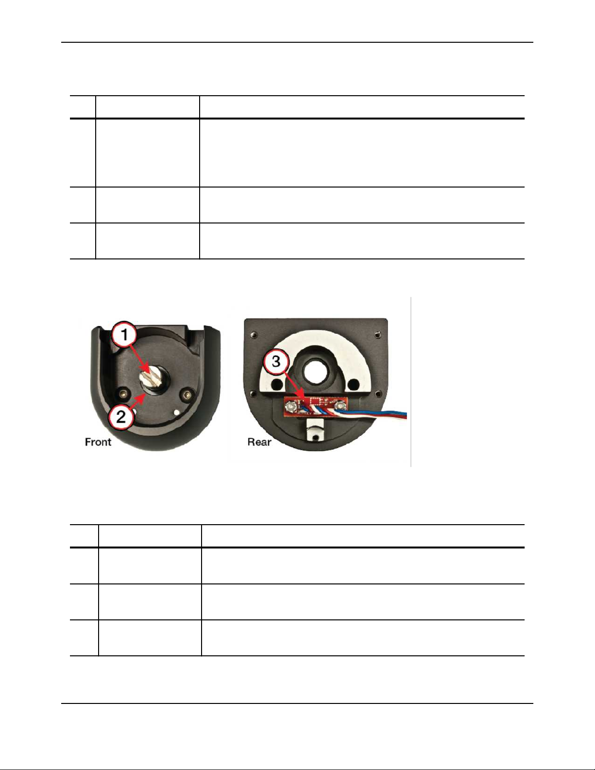
Pump Raceway
1
Pump motor shaft
2
Pump seal
3
Hall-effect sensor
Figure 1-10: Pump raceway housing components
Table 1-5: Pump raceway housing components
Component Function
1 Pump motor shaft Transfers rotation to the pump rotor. The shaft has a one-quarter-turn slot that is
used to attach the rotor.
2 Pump seal Prevents fluid from entering the device. It is a rubber seal between the pump motor
shaft and the pump raceway housing.
3 Hall-effect sensor Senses pump speed by detecting when the magnet in the pump rotor passes over
it.
Trima Accel® Automated Blood Collection System • Service Manual 1-17
Operational Description
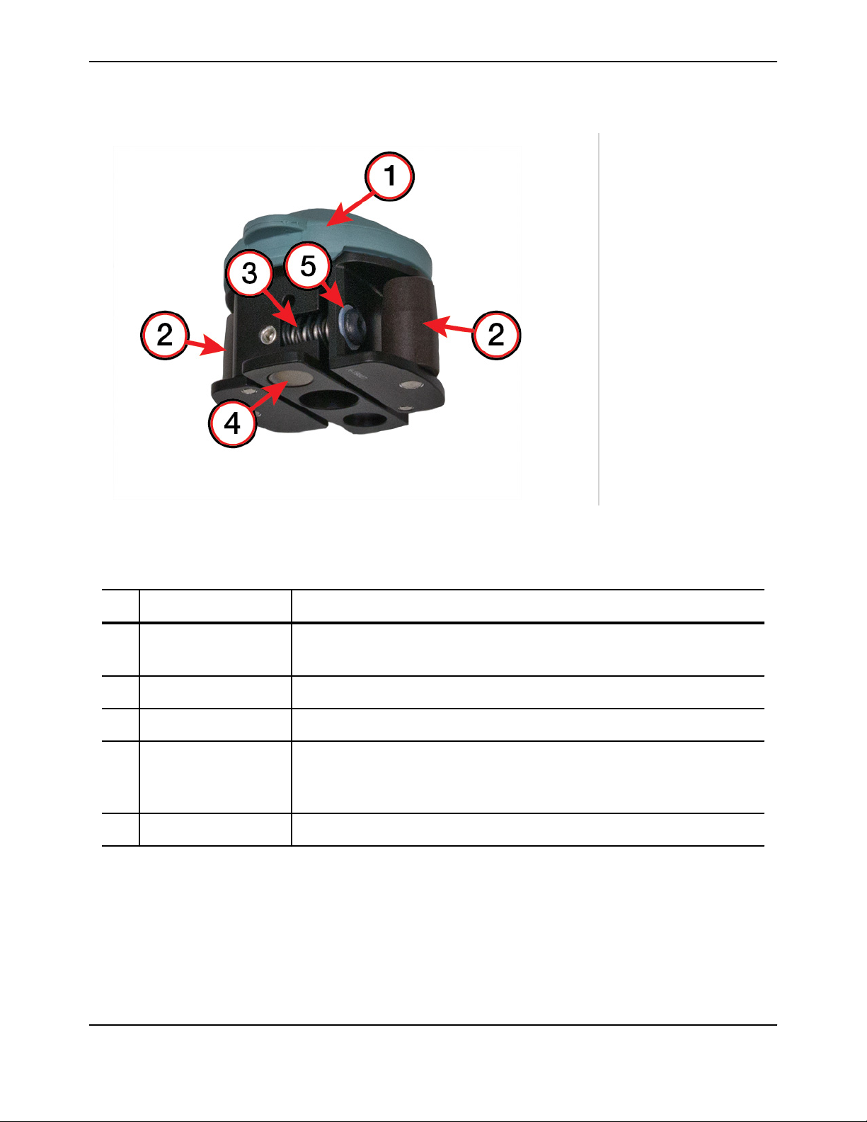
Pump Rotor
1
Rotor cap
2
Roller
3
Roller spring
4
Magnet
5
Rotor washer
Figure 1-11: Pump rotor components
Table 1-6: Pump rotor components
Component Function
1 Rotor cap Catches the disposable tubing with a tab when the set is loading to ensure that the
tubing line is drawn down into the raceway housing.
2 Roller Pushes against the tubing to create the peristaltic action of the pump.
3 Roller spring Applies force to the roller to enable it to pinch the tubing closed as the pump rotates.
4 Magnet Activates the Hall-effect sensor in the raceway housing as it passes over the sensor.
The platelet pump rotor (indicated with a dot on the rotor cap) is the only rotor with
two magnets; all of the other rotors have only one magnet.
5 Rotor washer Decreases clicking noises during rotation. It is a clear plastic washer.
1-18 Trima Accel® Automated Blood Collection System • Service Manual

Sensor System
Sensor System
The sensor system is made up of multiple sensors and detectors that monitor pressure, fluid levels, leaks,
door position, lock status, and platelet line composition.
The input for sensor systems consists of variable analog information, and the input for detector systems
consists of binary on/off information.
The sensor system is made up of the following:
• Two pressure sensors
• Two reservoir level sensors
• The RBC detector
• The anticoagulant (AC) detector
• The leak detector
Motion Feedback Systems
Optical encoders and Hall-effect sensors are used in various subsystems as a feedback loop. These sensor
systems are often paired together, where the primary signal is obtained from one sensor and must match
the secondary signal obtained from the other sensor.
Optical encoders are used by the pumps, the valves, the centrifuge, and the door lock system. All of these
are monitored by the control system except for the door lock system, which is monitored by the safety
system. They function by sensing interruptions in a light beam, counting these interruptions, and
sending that data to the feedback system.
Hall-effect sensors are used as part of the feedback loops for the safety system, and one is used to give door
position information. The Hall-effect sensors are used in the centrifuge motor, the pump housing
raceways, and the door closed sensor. All of these are monitored by the safety system except for the door
closed sensor, which is monitored by the control system. The Hall-effect sensors function when a
transducer senses a magnetic field and then converts that field sensing to an electrical signal that is sent to
the feedback system. The safety system counts these pulses to compare against what the control system
sees with the optical sensors.
There are closed loop and open loop conditions to the feedback systems. Closed loop is the default
condition that uses sensor-derived feedback to directly control the system. An open loop condition
removes the sensor-derived information from the feedback loop.
Trima Accel® Automated Blood Collection System • Service Manual 1-19
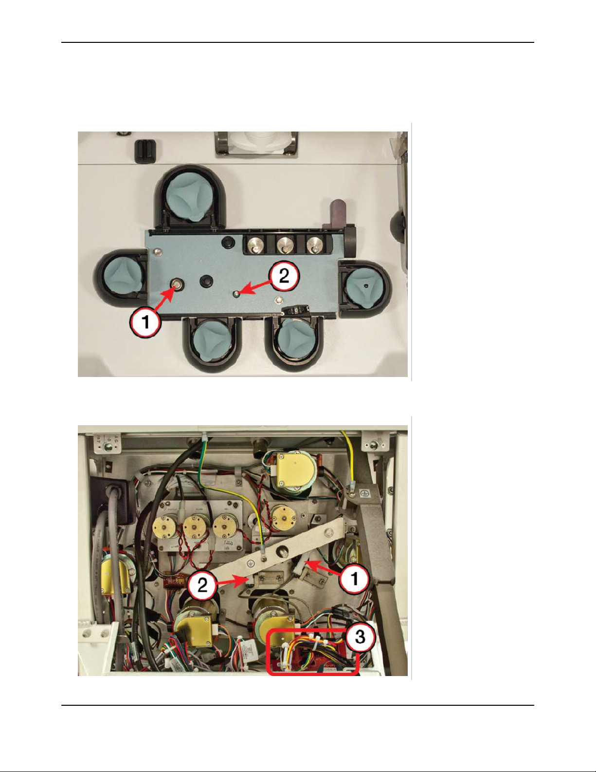
Operational Description
Pressure Sensors
There are two pressure sensors on the front panel of the Trima Accel system, which monitor the draw/
return donor access pressure and the centrifuge pressure.
1
Access/return
pressure sensor
2
Centrifuge pressure
sensor
Figure 1-12: Pressure sensor locations (front)
1
Access/return
pressure sensor
2
Centrifuge pressure
sensor
3
Adapter CCA
Figure 1-13: Pressure sensor locations (rear)
1-20 Trima Accel® Automated Blood Collection System • Service Manual
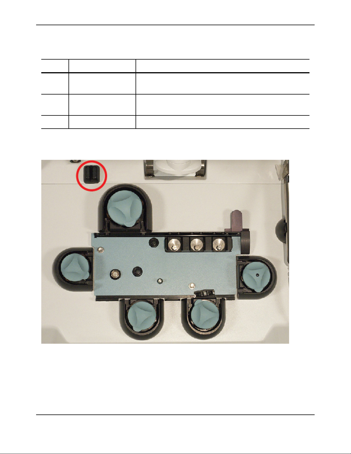
Table 1-7: Pressure sensor system components
Component Function
Sensor System
1 Access/return pressure
sensor
2 Centrifuge pressure
sensor
3 Adapter CCA Connects the pressure sensor connectors to the wiring harness connectors.
Monitors the fluid pressure that is either coming from or going to the donor.
Monitors the fluid pressure inside the centrifuge channel.
AC Sensor
The anticoagulant (AC) sensor indicates the presence of AC.
Figure 1-14: The AC sensor
Trima Accel® Automated Blood Collection System • Service Manual 1-21
 Loading...